1
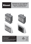
INTRODUCTION
This instrument is a portable easy to use 3½ digit, compact-sized digital infrared
thermometer with laser sighting designed for simple one hand operation. The
meter comes with backlit LCD display, Auto-hold function and auto power down
(15 seconds approx.) after releasing MEAS button to extend battery life.
INSTRUCTIONS
IR90
DANGER
Pressing the
button turns the laser beam on and off. Exercise extreme
care and do not allow the laser beam to enter your eye or those of any other
person or animal.
• Do not look directly into the laser light from the optical system.
• When measuring the temperature of an object which has a mirror finish, be
sure not to allow the laser light beam to be reflected off the surface into your
eyes or those of another person.
• Do not allow the laser light beam to impinge upon any gas which can
explode.
INFRARED ELECTRICAL
Temperature Range: -20°C to 550°C / -4°F to 1022°F
Display Resolution: 0.5°C / 1°C (Auto), 1°F
Accuracy: ±2% of reading or ±3°C / 6°F, whichever is greater @ 18 to 28°C (@
INFRARED & K-TYPE
THERMOMETER
MARTINDALE
ELECTRIC
64.4 to 82.4°F) ambient operating temperature.
Temperature Coefficient: ±0.2% of reading or ±0.2°C /0.36°F, whichever is
greater, change in accuracy per °C/°F change in ambient operating temperature
above 28°C/82.4°F or below 18°C/64.4°F.
Response Time: 1 second
Spectral Response: 6 to 14μm nominal
Trusted by professionals
3
Emissivity: 0.10 to 1.00 by step of 0.01
Temperature Coefficient: ±0.2% of reading or ±0.36°F/0.2°C, whichever is
Detection Element: Thermopile
greater, change in accuracy per °F/°C change in ambient operating temperature
Optical Lens: Fresnel Lens
above 82.4°F/28°C or below 64.4°F/18°C.
Sighting: 1-beam laser marker <1mW (class 2)
Input Protection: 24V dc or 24V ac rms maximum input voltage on any
Field of View: 100mmØ at 1000mm (3.9"Ø at 39.0") Spot size increases with
combination of input pins.
distance from the probe tip as shown (Spot Diameter measured at 90 % Energy)
Input Connector: Accepts standard miniature thermocouple connectors (flat
blades spaced 7.9mm, center to center).
Diameter of spot (mm)
SPECIFICATIONS
100Ø
50Ø
16
25Ø
250
500
1000
GENERAL
Laser
marker
Display: 3½ digit liquid crystal display (LCD) with maximum reading of 1999
Distance of object (mm)
Spot size increases with distance from the probe tip as shown
(Spot Diameter measured at 90 % Energy)
Low battery indication: the "
" is displayed when the battery voltage drops
below the operating level
Measurement rate: 1 times per second, nominal.
Operating Environment: 0°C to 50°C (32°F to 122°F) at <80% relative humidity
Storage Temperature: -20°C to 60°C (40°F to 140°F) , 0 to 80% R.H. with
K-type thermocouple ELECTRICAL
battery removed from the meter
Auto power off: 15 seconds.
Temperature Scale: Celsius or Fahrenheit user-selectable
Standby current consumption : <20μA
Measurement Range:
Battery: 9 volt battery. (NEDA 1604, IEC 6F22)
Thermocouple
K-TYPE
Range
-200°C to 1372°C, -328°F to1999°F
Dimensions: 170mm(H) x 65.5mm(W) x 35mm(D)
Weight: 195g (including probe and batteries)
Auto range: 0.1°C/1°C , 0.1°F/1°F
Accuracy: Accuracy is specified for operating temperatures over the range of
Laser Specifications
18°C to 28°C (64°F to 82°F), for 1 year, not including thermocouple error.
Laser safety classification of Class II
±(0.1%rdg+1°C) on -50°C to 1372°C
Wave Length: Red (670nm).
±(0.1%rdg+2°C) on -50°C to -200°C
Operating Distance: 2 to 50 feet.
±(0.1%rdg+2°F) on -58°F to 1999°F
Power out: <1mW , class II laser product.
±(0.1%rdg+4°F) on -58°F to -328°F
4
5
CAUTION
• Do not use the unit near any device which generates strong electromagnetic
radiation or near a static electrical charge, as these may cause errors.
• Do not use the unit where it may be exposed to corrosive or explosive
gases. The unit may be damaged, or explosion may occur.
• Do not keep or use this unit in an environment where it will be directly
illuminated by sunshine, or where it will be exposed to high temperatures,
high humidity or condensation. If you do, its insulation may be damaged, or
OPERATING INSTRUCTIONS
Turning the Power on
When the power is off, press MEAS button to turn on the meter. The values and
settings on the LCD return to what they were before the power was last turned
off.
Auto Power-down function
If unused for about 15 seconds, the meter will power-down automatically. Press
MEAS button to switch unit back on.
it may no longer function according to specification.
Display Back-Light Button
• Do not point the lens at the sun or at any other source of strong light. If you
Press "
do, the sensor may be damaged.
• Do not allow the lens to come into contact with any object where
" button to turn on or off the LCD Back Light during measurement, or
while the display shows HOLD, MAX or MIN.
temperature is to be measured. Do not allow the lens to become dirty,
scratched or fouled with foreign material - doing so may cause errors.
• Do not touch or hold by the front cone. Temperature reading can be affected
Laser Sighting
Press "
" button to activate the laser. "
MEAS button. Laser will light and "
by heat from hand.
• Do not place the meter on or around hot objects (70°C/158°F). It may cause
damage to the case.
" will be present on display. Press
" will blink on display. Release MEAS to
revert to standby.
MEAS (MEASURE) Button
• If the meter is exposed to significant changes in ambient temperature (hot to
Press MEAS button once to turn on the meter. To measure temperature, press
cold or cold to hot). Allow 20 minutes for temperature stabilisation, before
and hold MEAS. Release MEAS button to stop measuring. This will
taking measurements.
automatically hold the display reading. The meter powers down automatically
• Condensation may form on the lens when going from a cold to hot
after 15 seconds.
environment. Wait 10 minutes for condensation to dissipate before taking
Selecting the Temperature Scale (°C or °F)
measurements.
• This unit is not constructed to be water proof or dustproof, so do not use it
in a very dusty environment or in one where it will get wet.
Readings are displayed in either degrees Celsius (°C) or degrees Fahrenheit
(°F). When the thermometer is turned on, it is set to the temperature scale that
was in use when the thermometer was last turned off. To change the
temperature scale, in power down mode, press & hold the "
"
" button for (°F) or
" button for (°C) and press MEAS button until °F or (°C) is displayed.
7
6
Continuous Measurement
MIN:
1. When the unit is powered down, hold the MODE key down and press the
The Minimum temperature during measurement is displayed. When
measuring, press the mode key. This will cycle between MAX/MIN/
MEAS key. This will put the meter into the continuous measurement mode.
Present temperature.
K:
Temperature measurements are taken by the K-type thermocouple
2. Press the MEAS key again to stop measuring temperature. This will
automatically hold the display reading. Press again to revert to continuous
SET MODE & Numeric input key
measurement. The meter will power down automatically after 15 seconds if hold
"SET" indicator is displayed when a numerical value can be set (during setting
is displayed.
of e, ALM Hi and ALM Lo).
" L " key: The numerical value is increased.
NOTE: During the continuous measurement mode, the HOLD indication does
not appear.
" M " key: The numerical value is reduced.
If either of these numerical value keys is held down, the numerical value
changes rapidly in the appropriate direction.
MODE SELECTION (Second display)
Press the MODE button to cycle between
ε V ALM Hi V ALM Lo V MAX V
How to specify the thermal emissivity (ε )
1. Apply black tape to the object where temperature is to be measured, or
spray it with matt black spray paint. Wait for all the temperatures to stabilise.
MIN V K V HOLD.
2. Set the thermal emissivity value (ε) on the LCD to 0.95.
HOLD:
3. Press the MEAS key, so as to measure the temperature (T1) of the part
Releasing MEAS button stops measuring temperature, HOLD is
displayed, and the measured temperature is held.
ε:
Set the thermal emissivity of the object set using the L and M keys
ALM Hi:
The upper limit alarm temperature is set using the L and M keys.
When the measured temperature exceeds the Hi setpoint, the
beeper emits a pulsed tone and "ALM Hi" is displayed.
ALM Lo:
on which tape (or black spray paint) is applied.
4. Measure the temperature (T2) of the parts to which tape (or black spray
paint) is not applied.
5. Change the thermal emissivity value (ε).
6. The value of the thermal emissivity (ε) at which T1 comes out to be equal to
The lower limit alarm temperature is set using the L and M keys
T2 is the correct value for the inherent thermal emissivity of the body
When the measured temperature is below the Lo setpoint, the
whose temperature is to be measured.
beeper emits a continuous tone and "ALM Lo" is displayed.
MAX:
The maximum temperature during measurement is displayed. When
measuring, press the mode key. This will cycle between MAX/MIN/
Present temperature
8
9
6. If the surface to be measured is highly reflective, apply masking tape or matt
MEASUREMENT CONSIDERATIONS
finish black paint to the surface.
1. Theory of Measurement
Every object emits infrared energy in accordance with its temperature. By
7. If the meter seems to be giving incorrect readings check the front cone.
measuring the amount of this radiant energy, it is possible to determine the
There may be condensation or debris obstructing the sensor; clean per
temperature of the emitting object.
instructions in the maintenance section.
2. About Infrared
Infrared radiation is a form of light (electromagnetic radiation), and has the
property that it passes easily through air while it is easily absorbed by solid
matter. With an emission thermometer which operates by detecting infrared
OPERATION
INFRARED Measurements (Main display)
radiation accurate measurement is possible, irrespective of the air temperature
1. When the power is down, pressing MEAS button turns on the power.
or the measurement distance.
2. Use "
" button to turn on or turn off the display Back-Light.
3. Emission Thermometer Structure
3. Use "
Infrared radiation which has been emitted from the object is focused upon an
4. Press the MODE button, if necessary to set the thermal emissivity value (e).
infrared radiation sensor, via an optical system. This includes a lens which is
5. Point the lens at the object where temperature is to be measured.
transparent to infrared radiation, and a 5.3μm cut off filter. The output signal
6. Press the MEAS button. Measurement is performed as long as the MEAS
from the infrared radiation sensor is input to an electronic circuit along with the
button is kept pressed.
output signal from a standard temperature sensor (Thermopile).
7. Referring to the spot size figure, aim the laser beam at the object where
" button to turn on or turn off the Laser beam.
temperature is to be measured.
4. Emissivity
All objects emit invisible infrared energy. The amount of energy emitted is
proportional to the object's temperature and its ability to emit IR energy. This
ability, called emissivity, is based upon the material that the object is made of
and its surface finish. Emissivity values range from 0.10 for a very reflective
object to 1.00 for a perfect black surface. The Factory set emissivity value is
0.95, which covers 90% of typical applications.
NOTE: Although the field of measurement (or Field of View) and the spot almost
coincide, the actual field of measurement corresponds to the diameter for 90%
optical response. The measured object needs to be larger than the diameter
(size of spot) by an adequate margin at least 1.5 to 2 times bigger.
8. Read the display.
K thermocouple Measurements (Second display)
5. If the surface to be measured is covered by frost or other material, clean it to
expose the surface.
1. When the power is off, press the MEAS button to power up the unit.
2. Press the MODE button to switch to the K mode
3. Use "
" button to turn the display Back-Light on and off if necessary.
10
11
4. Connect the type K thermocouple to the jack on the base of the instrument.
Martindale Electric will carry out routine calibration (on a chargeable basis) if the
Place the probe or thermocouple tip on or in the material to be measured.
instrument is returned, carriage paid, to the address on the final page of this
5. Press the MEAS button. Measurement is performed as long as the MEAS
document. Alternatively, a chargeable collection and return service is available.
button is kept pressed.
Repair & Service
6. Read the display.
There are no user serviceable parts in this unit. Return to Martindale Electric
MAINTENANCE
Company Ltd if faulty. Our service department will promptly quote to repair any
faults that occur outside the warranty period.
Battery Replacement
Power is supplied by a 9 volt "transistor" battery. (NEDA1604, IEC 6F22). The
Storage Conditions
"
The unit should be kept in warm, dry conditions away from direct sources of
" appears on the LCD display when replacement is needed. To replace the
battery, remove the two screws from the back of the meter and lift off the
heat or sunlight, with the battery removed and in such a manner as to preserve
battery cover. Remove the battery from the battery contacts.
the working life of the unit. It is strongly advised that the unit is not kept in a
tool box where other tools may damage it.
Cleaning
Periodically wipe the case with a damp cloth. Do not use abrasives or solvents.
Warranty
Faults in manufacture and materials are fully guaranteed for 2 years from date
of invoice and will be rectified by us free of charge, provided the unit has not
Substance
Thermal emissivity
Substance
Thermal emissivity
Asphalt
Concrete
Cement
Sand
Earth
Water
Ice
Snow
Glass
Ceramic
Marble
Plaster
Mortar
Brick (red)
0.90
0.94
0.96
0.90
0.92
0.92
0.96
0.83
0.90
0.90
0.94
0.80
0.89
0.93
Cloth (black)
Human skin
Leather
Charcoal (powder)
Lacquer
Lacquer (matt)
Rubber (black)
Plastic
Timber
Paper
Chromium oxides
Copper oxides
lron oxides
Textiles
0.98
0.98
0.75
0.96
0.80
0.97
0.94
0.85
0.90
0.70
0.81
0.78
0.78
0.90
to 0.98
to 0.96
to 0.96
to 0.98
to 0.95
to 0.94
to 0.90
to 0.91
to 0.96
been tampered with and is returned to us with its housing unopened. Damage
due to dropping, abuse or misuse is not covered by the guarantee. Nothing in
these instructions reduces your statutory rights.
to 0.80
to 0.95
to 0.95
to 0.94
to 0.82
Range: -4°F to 1022°F, -20°C to 550°C
Emissivity: 0.1 to 1.0, user selectable
9V
NEDA 1604 6F 22 006P
LASER RADIATION DO NOT STARE
INTO BEAM SEMICONDUCTOR
LASER 670nm MAX. 1mW CLASS II
LASER PRODUCT IEC 60825-1:1993
12
13
Martindale Electric Company Ltd was founded in 1928 and
manufactures a large range of electrical test equipment.
G
16th Edition Testers
G
All-In-One Testers
G
Calibration Equipment
G
Continuity Testers
G
Electrician’s kits
G
Full Calibration & Repair Service
G
Fuse Finders
G
Digital Clamp Meters
G
Digital Multimeters
G
Microwave Leakage Detectors
G
Motor Maintenance Equipment
G
Non-trip loop testers
G
Pat testers & Accessories
G
Phase rotation
G
Proving units
G
Socket Testers
G
Thermometers & Probes
G
Test Leads
G
Voltage Indicators
+
G
Specialist Metrohm testers (4 & 5kV)
G
Specialist Drummond testers
Martindale Electric Company Limited
Metrohm House, Penfold Trading Estate, Imperial Way, Watford, WD24 4YY.
Tel: +44 (0)1923 441717 Fax: +44 (0)1923 446900
E-mail: [email protected]
Website: www.martindale-electric.co.uk
E+OE. © Martindale Electric Co. Ltd. 2004