1
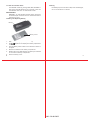
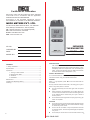
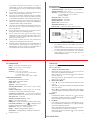
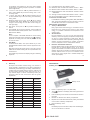
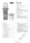
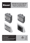
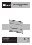
® ® Certificate of Calibration We hereby certify that this product has been calibrated and found to be in accordance with the applicable SPECIFICATIONS and STANDARDS. Accuracies of the standard equipment used in this calibration are traceable to the National Standards. MECO METERS PVT. LTD. Plot No. EL-60, MIDC Electronic Zone, TTC Industrial Area, Mahape, Navi Mumbai - 400710 (INDIA) Tel : 0091-22-27673311-16, 27673300 (Board) Fax : 0091-22-27673310, 27673330 E-mail : [email protected] Web : www.mecoinst.com SR. NO. DUAL INPUT THERMOMETER : CHECKED BY : DATE : MODEL : 901 MODEL NO. : USER MANUAL Contents 1. Safety Information ........................................................... 3 2. Specifications .................................................................. 4 3. Operations ....................................................................... 5 1. Turning on and off meter ............................................ 5 2. Measurement Mode .................................................... 5 3. Set Mode ..................................................................... 6 4. Hold Mode ................................................................... 7 4. Maintenance .................................................................... 8 5. Installing and Replacing Battery ..................................... 8 6. Cleaning ........................................................................... 9 SAFETY INFORMATION It is recommended that you read the safety and operation instructions before using the thermometer. WARNING To avoid electrical shock, do not use this instrument when working voltages at the measurement surface over 24V AC or DC. WARNING To avoid damage or burns, do not make temperature measurement in microwave ovens. CAUTION Repeated sharp flexing can break the thermocouple leads. To prolong lead life, avoid sharp bends in the leads, especially near the connector. 2 3 901 : 28-09-2012 SPECIFICATIONS Range : K-TYPE(0.1°C) -100°C to 1372°C K-TYPE(1°C) -100°C to -200°C K-TYPE(0.1°F)-100°F to 2000°F K-TYPE(1°F) 2000°F to 2501°F K-TYPE(1°F) -100°F to -328°F Unit : Celsius or Fahrenheit Resolutions : 0.1°C/1°C, 0.1°F/1°F Measurement rate : 1 time/second. Accuracy : ±(0.1%rdg+1°C) on -60°C to 1372°C ±(0.1%rdg+2°C) on -60°C to -200°C ±(0.1%rdg+2°F) on -76°F to 2501°F ±(0.1%rdg+4°F) on -76°F to -328°F According to temperature standard ITS-90. Accuracy : Stated accuracy at 18°C to 28°C (64°F to 82°F), <75% R.H. not including thermocouple error. Temperature Coefficient : 0.1 times the applicable accuracy specification per °C out of 18°C to 28°C (64°F to 82°F). Operating environment : 0°C to 50°C(32°F to 122°F) at <70% R.H. Storage temperature : -20°C to 60°C(-4°F to 140°F), 0 to 80% R.H. with battery removed from meter. Low battery indication : The " " is displayed when the battery voltage drops below the operating level. Battery : 1.5V x 2pcs AAA size. Battery Life : 250 hours typical with alkaline battery. Dimensions : 25 x 51 x 133mm (approx.) Weight : 150gms including batteries (approx.) Accessories : 1.5V AAA battery (installed) x 2, Wristlet x 1, Protection cap x 1, K-type thermocouple (upto 2600C) x 2 OPERATIONS There are 3 operation modes, namely Measurement Mode, Set Mode and Hold Mode. 1. Turning on and off meter : When power is off, make sure the k-type thermocouple was inserted to meter, a short push on " " key turns on the meter and enter Measurement Mode. 2. In measurement mode, a short push on " " key turns on the backlight for dark environment, it goes off automatically after 15 seconds if without further operation. Relative Mode : In measurement mode, short push on "s" key to enter relative mode with indicator "REL" shows at bottom of LCD. After entering this mode, the meter will zero the display and store last measurements as a reference values. Shown on display are the relative values against these reference values. Change reference value: Short push on "s" key again, meter will store last measurement as a reference value again. Exit relative mode : Hold "s" key for 2 seconds to exit relative mode. 5 4 3. Set Mode : In set mode, user can turn on/off APO function, measurement unit and set thermocouple offset of T1 and T2. (APO = Auto Power Off, when APO is ON, the meter power off automatically if no operation in 10 minutes) When power is off, press and hold " to enter Set Mode. " key for 2 seconds In Set Mode, press "Mode" key each time move settable position/digit in following sequence (indicator of settable position/digit blinks.) 3.7 Digit to the left of decimal point of T2 offset blinks, short push on "s" key increases this digit from 0 to 9 and then to 0. Push "MODE" key to save the setting and enter setting +/- sign of T2 offset. 3.8 Under line of +/- sign of T2 offset blinks, short push on "s" key switches between "no sign (+)" and "-". Push "MODE" key to save the setting, exit setting mode and enter Measuring mode after checking procedure. (Please refer to the section of Measurement Mode.) Note : To turn off power in Set Mode abandon the current setting and previous settings remain unchanged. If " " indicator appeared, the setting value can works till power off but did not save to meter. 3.1 APO ON/OFF : short push on "s" key switches between ON and OFF. Push "MODE" key to save APO setting and enter to setting measurement unit. 3.2 Measurement unit : short push on "s " key switches between °C and °F. Push "MODE" key to save unit setting and enter to setting to the right of decimal point T1 offset. 3.3 Digit to the right of decimal point of T1 offset blinks, short push on "s" key increases this digit from 0 to 9 and then to 0. Push "MODE" key to save the setting and enter setting digit to the left of decimal point. 3.4 Digit to the left of decimal point of T1 offset blinks, short push on "s" key increases this digit from 0 to 9 and then to 0. Push "MODE" key to save the setting and enter setting +/- sign of T1 offset. 3.5 Under line of +/- sign of T1 offset blinks, short push on "s" key switches between "no sign (+)" and "-". Push "MODE" key to save the setting and enter setting digit to the right of decimal point of T2 offset. 3.6 Digit to the right of decimal point of T2 offset blinks, short push on "s" key increases this digit from 0 to 9 and then to 0. Push "MODE" key to save the setting and enter setting digit to the left of decimal point. When power is on, press and hold " " key for 2 seconds to turns the power off. Measurement Mode : If there are thermocouples in the input sockets, measurement starts immediately. If thermocouple is not in the input socket before turning on, the display of respective channel shows "OL". Once thermocouple is inserted, measurement starts immediately, but record function did not work immediately till 3 times update of temperature readings. Backlight : 4. Hold Mode : In Measurement Mode, short push "Mode" key to enter Hold Mode with indicator "HOLD" shows at upper left corner of LCD. Right after entering this mode, shown in the LCD is the last measurement and the reading will not be updated with new measurement. Push "Mode" key each time the display changes in following sequence: 4.1 Last Measurement: with indicator "HOLD". 4.2 Maximum value recorded: with indicator "HOLD" + "MAX". 4.3 Minimum value recorded: with indicator "HOLD" + "MIN". 4.4 Maximum-Minimum value recorded: with indicator "HOLD" + "MAX-MIN". 4.5 Average of values recorded: with indicator "HOLD" + "AVG". 4.6 Exit the Hold Mode and return to Measurement Mode. 6 7 901 : 28-09-2012 To clear the recorded values : Cleaning In Hold Mode and during viewing MAX, MIN, MAX-MIN or AVG, press and hold "Mode" key for 2 seconds, to clear the recorded data and return to measurement mode. Periodically wipe the case with a damp cloth and detergent, do not use abrasives or solvents. MAINTENANCE WARNING : To avoid possible electrical shock, disconnect the thermocouple connectors from the thermometer before removing the cover. Installing and Replacing Battery Battery Battery Cover 1. Power is supplied by 2pcs 1.5V (AAA SIZE). 2. The " " appears in the display when battery replacement is needed. 3. Push the Battery Cover and lift it in the direction as shown in the figure. 4. Remove the batteries from battery compartment. 5. Replace with 2 new AAA batteries with polarity as indicated on the bottom of Battery Compartment. 6. Place the Battery Cover. 8 9 901 : 28-09-2012 ® ® Certificate of Calibration We hereby certify that this product has been calibrated and found to be in accordance with the applicable SPECIFICATIONS and STANDARDS. Accuracies of the standard equipment used in this calibration are traceable to the National Standards. MECO METERS PVT. LTD. Plot No. EL-60, MIDC Electronic Zone, TTC Industrial Area, Mahape, Navi Mumbai - 400710 (INDIA) Tel : 0091-22-27673311-16, 27673300 (Board) Fax : 0091-22-27673310, 27673330 E-mail : [email protected] Web : www.mecoinst.com SR. NO. INFRARED THERMOMETER : CHECKED BY : DATE : MODEL : 910 MODEL NO. : USER MANUAL Contents INTRODUCTION This instrument is a infrared thermometer. Main (upper) display shows the measurement of IR thermometer. Lowerleft display shows the temper-ature of air surrounding the meter. Lower-right dis-play show the difference between IR measurement and air temperature (T). 1. Safety Information ................................................................ 3 Specifications ........................................................................... 5 Operations ................................................................................ 5 1. Turning on and off meter ............................................ 5 2. Measurement Mode .................................................... 5 3. Set Mode ..................................................................... 6 4. Hold Mode ................................................................... 7 SAFETY INFORMATION It is recommended that users read the safety and operation instructions before using the infrared thermometer. Maintenance ............................................................................. 8 DANGER Installing and Replacing Battery .............................................. 8 When " and off. Cleaning .................................................................................... 8 " sign appears, press "s" to turn the laser beam on Be very cautious with the laser beam, not aiming your eyes or those of any other person or animal. l Do not look directly into the laser light from the optical system. l When measuring the temperature of an object which has a mirror finish, be careful not to allow the laser light beam to be reflected off the surface into your eyes or those of another person. l Do not allow the laser light beam to impinge upon any gas which can explode. CAUTION 2 l Do not use the unit near any device which generates strong electromagnetic radiation or near a static electrical charge, as these may cause errors. l Do not use the unit where it may be exposed to corrosive or explosive gases. The unit may be damaged, or explosion may occur. l Do not keep or use this unit in an environment where it will 910 : 28-09-2012 3 be directly illuminated by sun-shine, or where it condensation. If you do, it may be deformed, its insulation may be dam-aged, or it may no longer function according to specification. l Do not place the meter on or around hot objects (70°C/ 158°F). It may cause damage to the case. l If the meter is exposed to significant changes in ambient temperature (hot to cold or cold to hot). Allow 30 minutes for temperature stabilization, before taking measurement. l Condensation may form on the sensor when going from a cold to hot environment-wait 10 minutes for condensation to dissipate before taking measurements. l This unit is not constructed to be waterproof or dust proof, so do not use it in a very dusty environment or in one where it will get wet. l Do not point the lens at the sun or at any other source of strong light. Doing so may damage sensor. l Do not contact the lens against the object whose temperature is to be measured, or get it dirty, allow it to be scratched, or allow any foreign material to adhere to it. Doing so may cause errors. l Do not touch or hold by the front case. Temperature reading can be affected by heat from hand. l Readings may be affected if the unit is operated within a radio frequency electromagnetic field strength of approximately 3 volts per meter, but the performance of the instrument will not be permanently affected. SPECIFICATIONS IR TEMPERATURE Temperature Range : -30°C to 550°C, -22°F to 1022°F Display Resolution : 0.1°C, 0.1°F Accuracy : ± (2°C/4°F) for -30°C to 100°C, (-22°F to 212°F) ± (2% reading) for 101°C to 550°C, (213°F to 1022°F) Response Time : 0.5 second Detection Element : Thermopile Spectral Response : 6 to 14μm Optical Lens : Fresnel Lens Adjustable emissivity (ε ) : 0.1 to 1.0 Field of View : 100mmØ at 600mm (2.4"Ø at 24.0") Note : 1. 2. 3. The distance between Laser marker and center of spot is 16mm. Spot size increases with distance from the probe tip as shown (Spot Diameter measured at 90% Energy). To ensure accurate measurement, the size of the object needs to 1.5 to 2 time of the spot size, so to provide adequate margin. 4 5 AIR TEMPERATURE OPERATIONS Range : -20°C to 60°C, (-4°F to 140°F) There are 3 operation modes, namely Measurement Mode, Set Mode and Hold Mode. Resolution : 0.1°C, 0.1°F 1. Sensor : Thermistor temperature sensor When power is off, a short push on " meter and enter Measurement Mode. Accuracy : ± 0.5°C for 0°C to 45°C ± 1.0°C for -20°C to 0°C, 45°C to 60°C ± 1.0°F for 32°F to 113°F ± 2.0°F for -4°F to 32°F, 113°F to 140°F When power is on, press and hold " turns the power off. LASER SPECIFICATIONS 2. Sighting : 1-beam laser marker. When "s" key is released the display freezes with reading of last measurement and indicator "HOLD" shows in middle of display. Storage Temperature : -20°C to 60°C (-4°F to 140°F), 0 to 80% R.H. with battery removed from meter. Backlight : In measurement mode, a short push on " " key turns on the backlight for dark environment, it goes off automatically after 15 seconds if without further operation. Auto power off : 10 minutes Standby consuming current : <5μA Battery Life : 40 hours (continuity) typical. (contain Laser) Low battery indication : The " " is displayed when the battery voltage drops below the operating level Dimensions : 25 x 51 x 133mm (approx.) Measurement Mode : While "s" key is pressed, measurement reading refreshed every 0.5 second. Operating Environment : -20°C to 60°C, (-4°F to 140°F) at <70% R.H. Battery : 1.5V x 2pcs AAA size " key for 2 seconds Press "s" key, to start measuring and activate the Laser pointer. Power out : <1mW. Temperature Coefficient : 0.1 times the applicable accuracy specification per °C out of 23°C±5°C, (73.4°F±9°F) " key turns on the Right after power on, all the indicators on the LCD display lights up for one second. Laser safety classification of Class 2 Wave Length : Red (630~670nm) Turning on and off the meter : 3. Set Mode : In set mode, user can select unit of tempera-ture (°C/°F), turn on/off differential temperature (T), adjust emissivity (ε) and turn on/off APO function. Weight : 120gms including battery (approx.) (APO = Auto Power Off, when APO is ON, the meter power off automatically if no operation in 10 minutes). Accessories : 1.5V AAA battery (installed) x 2, Wristlet x 1, Protection cap x 1 When power is off, press and hold " to enter Set Mode. 6 " key for 2 seconds 7 910 : 28-09-2012 In Set Mode, press "Mode" key each time move settable position/digit in following sequence (indicator of settable position/digit blinks.) 3.1 °C/°F Unit : short push on "s" key switches between °C and °F. Push "MODE" key to save the setting, enter T on/ off setting mode. 3.2 T on/off : short push on "s" key switches between on and off. Push "MODE" key to save the setting, enter Emissivity setting mode. 3.3 Emissivity setting (0.10 to 1.00) : Press "s" key to change the blinking digit. Press "MODE" key to select save, and change to the next digit or enter APO on/off setting (for most right digit). 3.4 APO on/off : short push on "s" key switches between on and off. 4.1 Last Measurement: with indicator "HOLD". 4.2 Maximum value recorded: with indicator "HOLD" + "MAX". 4.3 Minimum value recorded: with indicator "HOLD" + "MIN". 4.4 Maximum-Minimum value recorded: with in-dicator "HOLD" + "MAX-MIN". 4.5 Average of values recorded: with indicator "HOLD" + "AVG". 4.6 Exit the Hold Mode and return to Measurement Mode. To clear the recorded values : In Hold Mode and during viewing MAX, MIN, MAX-MIN or AVG, press and hold "Mode" key for 2 seconds, to clear the recorded data and return to measurement mode. Measurement Considerations 1. 3.5 Push "MODE" key to save the selection, exit set mode and Enter Measurement Mode (Please refer to the section of Measurement Mode.) 2. Note : Hold Mode : In Measurement Mode, short push "Mode" key to enter Hold Mode with indicator "HOLD" shows at upper left corner of LCD. 3. 4. Emission Thermometer Structure Infrared radiation which has been emitted from the object is focused upon an infrared radiation sensor, via an optical system. This includes a lens which is transparent to infrared radiation. And 5.3μm cut off filter. The output signal from the infrared radiation sensor is input to an electronic circuit along with the output signal from a standard temperature sensor (Thermopile). 9 Right after entering this mode, shown in the LCD is the last measurement and the reading will not be updated with new measurement. 8 About Infrared Infrared radiation is a form of light (electromagnetic radiation), and has the property that it passes easily through air while it is easily absorbed by solid matter. With an emission thermometer which operates by detecting infrared radiation accurate measurement is possible, irrespective of the air temperature or the measurement distance. To turn off power in Set Mode abandon the current setting and previous settings remain unchanged. If " " indicator appeared, the setting value can works till power off but did not save to meter. 4. Theory of Measurement Every object emits infrared energy in accordance with its temperature. By measuring the amount of this radiant energy, it is possible to determine the temperature of the emitting object. Push "Mode" key each time the display changes in following sequence : Emissivity MAINTENANCE All objects emit invisible infrared energy. The amount of energy emitted is proportional to the object's temperature and its ability to emit IR energy. This ability, called emissivity, is based upon the material that the object is made of and its surface finish. Emissivity values range from 0.10 for a very reflective object to 1.00 for a black body. Factory set emissivity value of 0.95, which cover 90% of typical applications. Installing and Replacing Battery Substance Thermal emissivity Substance Thermal emissivity Asphalt 0.90 to 0.98 Cloth (black) 0.98 Concrete 0.94 Human skin 0.98 Cement 0.96 Lather 0.75 to 0.80 Sand 0.90 Charcoal (powder) 0.96 Earth 0.92 to 0.96 Lacquer 0.80 to 0.95 Water 0.92 to 0.96 Lacquer (matt) 0.97 Ice 0.96 to 0.98 Rubber (black) 0.94 Snow 0.83 Plastic 0.85 to 0.95 Glass 0.90 to 0.95 Timber 0.90 Ceramic 0.90 to 0.94 Paper Battery Battery Cover 1. Power is supplied by 2pcs 1.5V (AAA SIZE). 2. The " " appears in the display when battery replacement is needed. 3. Push the Battery Cover and lift it in the direction as shown in the figure. 0.70 to 0.94 4. Remove the batteries from battery compartment. 5. Replace with 2 new AAA batteries with polarity as indicated on the bottom of Battery Compartment. 6. Place the Battery Cover. Marble 0.94 chromium oxides 0.81 Plaster 0.80 to 0.90 Copper oxides 0.78 Mortar 0.89 to 0.91 lron oxides 0.78 to 0.82 Brick (red) 0.93 to 0.96 Textiles 0.90 Cleaning Periodically wipe the case with a damp cloth and detergent, do not use abrasives or solvents. 910 : 28-09-2012