1
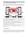
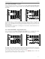
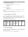
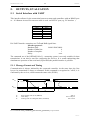
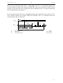
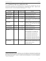
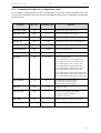
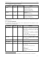
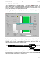
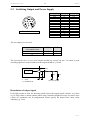
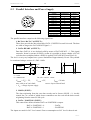
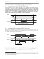
INFRASCAN3100 5. 29 Manual OUTPUTS, EVALUATION 5.1 Serial Interface with UART This interface allows for the connection between scanner and controllers with an RS422 port or – if a Remote Access Kit converter cable is used - an RS232C port (e.g. PC interface ). Signal Cable RxD /RxD TxD /TxD +24 V GND White Brown Green Yellow Pink Grey Die UART interface comprises two TxD and RxD signal lines: Interface protocol: Baudrate [Bd]: Number of data bits: Number of stopbits: Parity: 9600/19200/38400 8 1 even The command set of the INFRASCAN31.. measuring system is not only suitable for data transmission; it can also be used for configuring the receiver. It is worth emphasizing that simultaneous operation of the serial and (if provided) the parallel interface is possible. 5.1.1 Message Format and Timing Communication is always initiated by the connected controller. At the same time, the first byte to be transmitted is always a command. If this command is recognized as "valid", it is confirmed by the receiver, which returns the same code (ECHO). TxD S0 1 2 3 4 5 6 7 PS Control Data byte Command Rx Control 8 Byte transfer time (at 38,4kBaud): Time delay: Waiting time for subsequent data (command): 290 µs max..1500 µs8 max. 50 ms For commands write_transmitter_gain and write_special delay is up to 50 ms. Sitronic