1
Suretrol Manufacturing Inc.
NSC104A
Kiln Controller User's Manual
Suretrol Mfg. Inc. © 2013
NSC104A
Versions:
-
NSC104A 1.00
Revision Date: 2013
1
Suretrol Manufacturing Inc. | 343 Highway 2, Princeton Ontario Canada, N0J 1V0
NSC104A
Contents
Kiln Controller User's Manual ....................................................................................................................... 0
1.0 INTRODUCTION ....................................................................................................................................... 3
2.0 FUNCTIONAL DESCRIPTION..................................................................................................................... 3
3.0 USER INTERFACE ..................................................................................................................................... 4
3.1 ON/OFF SWITCH.................................................................................................................................. 4
3.2 -/+ SWITCH .......................................................................................................................................... 5
3.3 ENTER SWITCH .................................................................................................................................... 6
4.0 DISPLAY AND PROGRAMMING ............................................................................................................... 6
4.1 PROGRAMMING .................................................................................................................................. 6
4.1 TEMPERATURE DISPLAY ...................................................................................................................... 7
4.2 UPPER LIMIT TEMPERATURE DISPLAY ................................................................................................ 8
4.3 ADVANCE RATE DISPLAY ..................................................................................................................... 8
4.4 SET TEMPERATURE DISPLAY ............................................................................................................... 9
4.5 AUTOMATIC DAMPER CONTROL (Adc) ............................................................................................... 9
5.0 SENSOR SPECIFICATIONS ...................................................................................................................... 12
6.0 LED INDICATORS ................................................................................................................................... 13
7.0 ELECTRONIC ADVANCE ......................................................................................................................... 13
8.0 SENSOR DIAGNOSTICS .......................................................................................................................... 14
9.0 CONTROLLER INSTALLATION................................................................................................................. 15
10.0 SPARE PARTS LIST/OPTIONS ............................................................................................................... 15
10.1 CALL FOR SERVICE ........................................................................................................................... 16
LIMITED WARRANTY ............................................................................................................................... 16
INSTALLATION TIPS ................................................................................................................................. 18
SAMPLE SETUP ........................................................................................................................................ 19
COMMON PROBLEMS ............................................................................................................................. 20
2
Suretrol Manufacturing Inc. | 343 Highway 2, Princeton Ontario Canada, N0J 1V0
NSC104A
1.0 INTRODUCTION
The Suretrol Manufacturing, MA052X temperature controller is the next generation of
controller based on the highly reliable MA014X unit. It is a unique product developed specifically
to control the temperature and humidity during the curing process. This compact controller provides a
solution for controlling and monitoring the temperature and humidity in today's demanding environment.
The product line has been enhanced to include the control of the intake damper to maintain constant wet
bulb temperature. (Opinion 2) This model also has a “MAN/AUTO” switch so that the damper opening
can be set with the rotation of a potentiometer (MAN) or automatically with the “Adc” setting (AUTO).
The controller is programmed via three toggle switches. The controller is easy to
setup and operate; minimum effort is required for setup and changes.
The controller is easy to install on existing or new bulk kilns and replaces all the functions
of existing controls while providing a simultaneous numeric display of wet and dry bulb temperatures.
The controller has been developed through years of experience. Similar units from the product
family have been in operation for years with excellent reliability and performance.
The MA052X controller can be monitored remotely via wireless communication on the internet
and cell phones for even greater flexibility.
In 2013 the NSC104A superseded the MAO52x controller. Its features and operation principles
are nearly identical.
Suretrol Manufacturing is proud that you have chosen our product for
your demanding application. Every effort has been made to supply you with a reliable product.
2.0 FUNCTIONAL DESCRIPTION
The controller replaces all the existing controls on the bulk kiln. It controls the dry bulb and wet
bulb temperature with an electronic advance on the dry bulb. Both dry and wet temperatures
are displayed simultaneously on a numeric display, with a red and green three digit display for the dry and
wet bulb respectively.
The user may program the advance rate, the upper limit temperature; the starting temperature
and the wet bulb stop advance temperature. All the above programmable entries are via two toggle
switches located on the circuit board.
The controller has a unique power fail recovery system which does not require a battery, and all
stored memory is retained for a minimum of ten years. The operator settings are automatically recovered
when power returns to the system. If power fails the controller recovers when the power returns. It
remembers the settings from before the power interruption and continues from that point
when the power returns.
Suretrol Manufacturing Inc. | 343 Highway 2, Princeton Ontario Canada, N0J 1V0
3
NSC104A
The temperature displays are in degrees Fahrenheit and is displayed to the nearest degree. Three
digits are used for the temperature display. When the temperature is below 100 degrees, the leading zero
on the display is not displayed.
Two light emitting diodes (LEDS) which are an integral part of the left most digits on the
numeric displays are used to indicate the advance status information and the programming information.
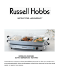
Figure 1 NSC104A Temperature Controller
A separate red LED is used to indicate the status of the burner. The location of the displays, LEDS
and the programming switches are detailed in Fig. 1.
3.0 USER INTERFACE
Three toggle switches are used to provide a user interface to the controller; they are used to
program all functions of the control. No additional user inputs are required for programming the control.
3.1 ON/OFF SWITCH
This switch is not used to turn the power ON/OFF on the controller. The function of this switch is
to determine if the controller is active and detect a power fail condition. The switch MUST be in the OFF
position before you start curing the kiln and it must remain in the ON position for the duration of the
curing cycle. When the curing cycle is complete it must be returned to the OFF position.
When the switch position is changed from OFF to ON the following sequence of events take
place:
1. The dry and wet bulb temperatures are measured and displayed in the kiln.
Suretrol Manufacturing Inc. | 343 Highway 2, Princeton Ontario Canada, N0J 1V0
4
NSC104A
2. The set point temperature and the upper limit temperatures are set to measure
dry bulb temperature.
3. The advance status is complete and the advance LED indicator is OFF.
4. The controller starts to control the temperature and display the dry and wet bulb temperatures
on the display.
In summary switching the ON/OFF toggle switch from the OFF to ON position RESETS all the
programmed temperature settings to the kiln temperature and controls the temperature based on the
above temperatures. This does not include the wet bulb set temperature. It also resets the clock to 0
hours.
If the switch is in the ON position and the main power comes back on the following sequence of
events take place:
The programmed values for set temperature advance rate, upper limit temperature and wet
bulb temperature is recovered from memory.
The temperature is controlled based on the programmed settings.
The dry and wet bulb kiln temperatures are displayed on the display.
CAUTION
THE SWITCH SOULD BE TURNED OFF WHEN THE CURE IS FINISHED, IF NOT THE CONTROL WILL
RESUME CURE WHERE THE LAST CURE ENDED (EG. 160-170 DEGREES)
3.2 -/+ SWITCH
This switch is used to change the following user programmable inputs, adjust selected parameter up
or down in program mode.
1. Upper limit temperature (ULt)
2. Advance Rate (Adr)
3. Set temperature (SEt)
4. Advance stop temperature or Wet bulb setting (Adc).
Suretrol Manufacturing Inc. | 343 Highway 2, Princeton Ontario Canada, N0J 1V0
5
NSC104A
When the switch is in the increase (INC) position the programmable entry will increment at
approximately 1 second rate. When the switch is in the decrease (DEC) position the programmable entry
will decrement at the preset rate of approximately 1 second, other rates are available.
This switch is active only when the display is in the program mode.
3.3 ENTER SWITCH
This switch has a dual function, which depends on the state of the display, selects your menus and
enters your selected value.
When you have the dry and wet bulb temperatures on the display, this switch is moved to the
ENTER position and released to change the display to the program mode.
When you are in the program mode and the switch is moved to the ENTER position
and released it will advance to the next programmed entry available and update the display accordingly.
This switch maybe used at any time to review the settings on the controller.
Selected menus are:
1. (Ult) upper limit ( 20-170 ) degrees Fahrenheit
2. (Adr) advance rate ¼ to 4.0 degrees Fahrenheit
3. (Set) set dry temperature ( 20-170 ) degrees Fahrenheit
- This menu is your normal thermostat
4. (Adc) wet bulb stop temperature (20-170) degrees Fahrenheit
- This automatically sets the wet bulb stop at Adc + 2 degrees Fahrenheit
4.0 DISPLAY AND PROGRAMMING
The controller has two three digit LED displays. Two different colors are used to differentiate
between temperatures. The RED display is used for dry bulb temperature and the GREEN display is
used for wet bulb temperature. All numeric displays are right justified with leading zeroes removed below
99 degrees Fahrenheit.
The display serves a multifunction purpose. It is used
to display the kiln temperatures, as well as the programming information when you are
programming the controller.
The format and a brief description of each display frame are described below.
4.1 PROGRAMMING
The controller is programmed via two toggle switches located on the front face. The user is
prompted for each entry on the display. When the entry appears on the display the numerical value maybe
increased or decreased via the -/+ toggle switch. To update the value press the ENTER switch
down and release it. This will update the program memory and advance to the next programmable entry.
Suretrol Manufacturing Inc. | 343 Highway 2, Princeton Ontario Canada, N0J 1V0
6
NSC104A
To enter the programming mode press the ENTER switchdownand release it.
The display in the programming mode changes to allow you to adjust the programmable
entries. The display in the programming mode has a numerical display and a three character description of
the parameter, which you are changing.
The programmable entries always appear on the display in the same order. The order of the
entries is as follows:
1.
2.
3.
4.
Upper Limit temperature ("ULt" on the GREEN display)
Advance rate ("Adr" on the GREEN display)
Set temperature ("SEt" on the GREEN display)
Automatic Damper Control ("Adc" on the RED display)
The -/+ key is used to change the setting by approximately one second intervals. When the
desired number is reached return the -/+ key to the center position, press and release the ENTER key to
store the new value, this will update the value in the controller memory and advance to the next entry in
the program sequence.
When you have made all the changes and you do not move any switch for a ten second interval
then the display will automatically return to the normal mode.
When a programming change is made the small indicator on the left most digit with the message
will be ON, this is an indication that a change has been made.
If you do not want to change an entry then make sure that this indicator is OFF before you press the
ENTER key to move to the next entry.
When you have reached the end of the menu sequence, press and release the ENTER key and the
next display will be the first entry in the program sequence.
4.1 TEMPERATURE DISPLAY
This display format is used to display the wet and dry bulb temperatures in the kiln. The -/+
switch has no effect on this display.
7
Suretrol Manufacturing Inc. | 343 Highway 2, Princeton Ontario Canada, N0J 1V0
NSC104A
4.2 UPPER LIMIT TEMPERATURE DISPLAY
This display format is used for the upper limit set point temperature or the temperature you
are advancing to. The upper limit set point temperature appears on the RED display and the message
"ULt" appears on the GREEN display.
4.3 ADVANCE RATE DISPLAY
This display format is used to display the programmed advance rate. The advance rate appears on
the RED display and the message "Adr" appears on the GREEN display. The GREEN display provides a
short description of the parameter, which you are changing.
8
Suretrol Manufacturing Inc. | 343 Highway 2, Princeton Ontario Canada, N0J 1V0
NSC104A
4.4 SET TEMPERATURE DISPLAY
This display format is used for the set temperature (SEt). This is the temperature where
your advance will start from. The set temperature appears on the RED display while confirmation
appears on the GREEN display.
4.5 AUTOMATIC DAMPER CONTROL (Adc)
This display format is used to display the wet bulb temperature that the control is keeping the kiln
at. The control will use the attached Belimo NMX24-SR damper actuator in order to open or close the
damper as required to reach and keep this temperature. The numeric temperature appears on the GREEN
display and the message "Adc" will appear on the RED display. If the current temperature is 2 degrees
above the Adc set temperature the control will stop the advance.
IF YOU HAVE A MA052X-1 OR OLDER SYSTEM THEN THIS DISPLAY WOULD
HAVE “ASt” AND THE SETTING WOULD BE THE TEMPERATURE AT WHICH THE CONTROL
ADVANCES THE DRY BULB.
Suretrol Manufacturing Inc. | 343 Highway 2, Princeton Ontario Canada, N0J 1V0
9
NSC104A
10
Suretrol Manufacturing Inc. | 343 Highway 2, Princeton Ontario Canada, N0J 1V0
NSC104A
PROGRAMMING NOTES
THE UPPER LIMIT TEMPERATURE ("ULT") CANNOT BE SET BELOW THE SET
("SET") TEMPERATURE, THIS MEANS THAT YOU CANNOT ADVANCE IN THE
REVERSE DIRECTION .
THE ADVANCE STOP FEATURE CAN BE DISABLED IF YOU DO NOT WANT TO USE IT.
IF YOU DON’T PLAN TO USE THIS FEATURE SIMPLY SET THE WET BULB TO
170 DEGREES FAHRENHEIT.
THE MINIMUM TEMPERATURE ENTRY FOR ANY PROGRAMMABLE PARAMETER IS
20 DEGREES FAHRENHEIT.
THE MAXIMUM TEMPERATURE ENTRY FOR ANY PROGRAMMABLE PARAMETER IS
170 DEGREES FAHRENHEIT.
WHEN CHANGING THE UPPER LIMIT TEMPERATURE OR THE ADVANCE RATE
AND THE CONTROLLER IS ADVANCING THE ADVANCE TIMERS WILL NOT CHANGE
AS IT IS ALWAYS OPTIMIZED FOR THE SHORTEST TIME .
YOU MAY VIEW ALL THE SETUP PARAMETERS WITHOUT MAKING ANY CHANGES
IN THE CONTROLLER MEMORY. THIS IS ACCOMPLISHED BY PRESSING
AND RELEASING THE ENTER KEY. EACH TIME THE KEY IS
PRESSED AND RELEASED THE NEXT PROGRAMMED ENTRY IS DISPLAYED . YOU WI
LLNOT CHANGE ANY ADVANCE RELATED TIMERS WHEN YOU VIEW THE
PROGRAMMED ENTRIES IF THE CONTROL IS IN THE ADVANCE MODE .
YOU CAN TERMINATE THE ADVANCE CYCLE IN TWO WAYS, INCREASING THE SET
TEMPERATURE TO THE UPPER LIMIT TEMPERATURE OR DECREASING THE
UPPER LIMIT TEMPERATURE TO THE SET TEMPERATURE .
REMEMBER
WHEN YOU MAKE A CHANGE TO PRESS AND RELEASE THE ENTER KEY.
11
Suretrol Manufacturing Inc. | 343 Highway 2, Princeton Ontario Canada, N0J 1V0
NSC104A
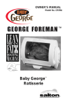
5.0 SENSOR SPECIFICATIONS
Waterless Sensor SM 2010
+ ½ degrees Fahrenheit accuracy – (20-180
degrees Fahrenheit)
True dry bulb
Calculated wet bulb from RH sensor
LOCATION OF SENSOR IN KILN
The sensor must be placed printing up, or slotted cover
down, in order to operate properly
The sensor needs to be located 2 feet (60 centimeters) in
from the burner cabinet
The sensor needs to be placed at least 1 foot (30
centimeters) in from the closest outer wall
It is recommended that the sensor wire be protected from
damage
SENSOR PINOUT
NOTICE:
IT IS IMPORTANT THAT THE SENSOR WIRES BE
CONNECTED SUCH THAT THEY ARE COLOR MATCHED
TO THE LABEL ON THE MAIN CIRCUIT BOARD
12
Suretrol Manufacturing Inc. | 343 Highway 2, Princeton Ontario Canada, N0J 1V0
NSC104A
6.0 LED INDICATORS
Several LED indicators are used to provide user feedback during programming and control
operation.
A RED LED display is used to indicate the status of the burner; when this LED is ON the
burner should be ON. When this LED is OFF the burner should be OFF. This indication is the output of
the controller and if the relay or burner is faulty the burner will not be ON.
There are two small LEDS located on the top left-hand corner of the left most digit on the RED
and GREEN displays. When in the control mode with the standard display the GREEN indicator
should always be OFF. The RED indicator in the normal display mode provides the
following information:
Indicator OFF: The advance is complete, upper limit and set temperatures are the same.
Indicator ON: The control is advancing to the upper limit temperature at the
programmed rate. The red display will also flash.
Indicator flashing: The control is advancing but the kiln wet bulb temperature is greater than the
programmed advance stop temperature. The dry bulb temperature will not
advance until the wet bulb temperature is less than or equal to the advance stop temperature (Adc
+2 degrees.)
A second LED is used in the program mode to indicate if you have changed an entry.
The LED for this purpose always appears on the same display as the message. When a change has
been made via the -/+ key, the indicator will be ON. If no changes have been made the indicator is OFF.
7.0 ELECTRONIC ADVANCE
The advance mechanism is entirely electronic with no moving parts. The advance timer is relative
and the user is not required to set a clock. When the advance rate is selected all the required timers are
automatically setup by the controller. If the advance rate or upper limit is changed when the controller is
advancing the controller will calculate the optimal time for the change which is the shortest time for the
next advance increment.
The following advance rates are available:
0.25 degrees per hour
0.50 degrees per hour
1.00 degree per hour
1.50 degrees per hour
2.00 degrees per hour
2.50 degrees per hour
3.00 degrees per hour
4.00 degrees per hour
Suretrol Manufacturing Inc. | 343 Highway 2, Princeton Ontario Canada, N0J 1V0
13
NSC104A
The advance rate timers are accurate to within one percent within the operating temperature
range.
8.0 SENSOR DIAGNOSTICS
The controller automatically monitors both sensors for faults, such as open sensor or shorted
sensor. When a sensor fault is detected the result is reported via the display.
When a sensor fails the message "DEF" will appear on the display.
If the wet bulb sensor fails the GREEN display will have the message "DEF" displayed. If the
advance stop is active the advance will continue at the programmed rate. A defective wet bulb sensor will
NOT stop the advance.
If the dry bulb sensor fails the RED display will have the message "DEF" displayed. The
burner will be shut OFF and the advance mechanism will continue to function.
If both sensors FAIL then both displays will have the message "DEF" displayed. The burner is
OFF.
The advance mechanism continues to function for all failure conditions. However the burner is
OFF in all cases if the dry bulb sensor fails.
NOTE:
SENSORS ARE CHECKED CONTINUOUSLY; HOWEVER CERTAIN FAILURES CANNOT BE
DETECTED. THE SYSTEM IS NOT A ONE HUNDRED PERCENT FAILSAFE.
IF A WRONG READING IS SUSPECTED, PLACE A GOOD HYGROMETER IN LOCATION AS CLOSE
AS POSSIBLE TO THE SUSPECTED SENSOR. IF READING IS MORE THAN 5 DEGREES FAHRENHEIT
DIFFERENT PLEASE CALL SERVICE.
WHEN ANY SENSOR IS DEFECTIVE CHECK THE CONTROLLER SETTINGS AND REMEMBER THE
ADVANCE MECHANISM CONTINUES TO OPERATE IF EITHER ONE OR BOTH SENSORS FAIL. IF THE
DRY BULB SENSOR FAILS THE BURNER IS AUTOMATICALLY SHUT OFF.
NSC104A CONTROLS ARE EQUIPPED WITH A SECOND SENSOR THAT IS USED FOR ERROR
CHECKING. THE CONTROL MUST HAVE BOTH SENSORS WITHIN 8 DEGREES FAHRENHEIT OR IT WILL
DISABLE THE BURNER
14
Suretrol Manufacturing Inc. | 343 Highway 2, Princeton Ontario Canada, N0J 1V0
NSC104A
9.0 CONTROLLER INSTALLATION
The controller is simple to install and uses a minimum amount of wiring.
The controller uses high intensity displays. These displays are brighter than the normal
displays. However the display is not visible in direct sunlight. The controller must not be mounted in
such a manner that the sunlight will be in direct contact with the display if possible.
The controller should be mounted inside the kiln/barn where it cannot get wet from rain or
ITEM
Complete Control
Sensor (Wet or Dry)
Power Supply
MODEL NUMBER
NSC104A
SM2010
MA099P1
Main Board
MA091P2 MARK V
REPLACES
MA052X-2
MAO62X
MA073P1
Replaces all previous main
boards
condensation on cold days. The controller will function properly in the humid environment; however
it WILL NOT operate if it gets wet.
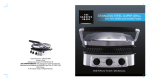
Refer to Figure 2 below for wiring particulars.
10.0 SPARE PARTS LIST/OPTIONS
NOTES:
Monitoring options:
1. EACH UNIT IS WIRELESS AND CONTAINS A MASTER RF TRANSCEIVER. A
SLAVE RF TRANSCEIVER UNIT (CL4490) IS REQUIRED FOR EVERY 128 KILNS
TO BE MONITORED. THE CL4490 UNIT IS LOCATED IN THE LAST KILN WITH
AN APPROPRIATE ANTENNA. ALL KILNS REQUIRE AN ADDRESS TO BE SET.
15
Suretrol Manufacturing Inc. | 343 Highway 2, Princeton Ontario Canada, N0J 1V0
NSC104A
10.1 CALL FOR SERVICE
FOR SERVICE PLEASE CALL:
JOE BUCEK
SURETROL MANUFACTURING INC.
United States of America
Suretrol USA
Joe Bucek
Cell: +1-252-294-8688
Business: +1-252-991-0533
Canada
Suretrol Manufacturing Inc.
Business: +1-519-458-4953
LIMITED WARRANTY
Suretrol Manufacturing warrants each NSC104A controller manufactured to be free from
defects in material and workmanship under normal use and service for the period of one year from
the date of initial purchase.
All warranty part replacement and repairs must be made by authorized service representatives
of Suretrol Manufacturing. Any outside work or alterations without the written approval from the
factory will render this LIMITED WARRANTY void.
The obligations by Suretrol Manufacturing specifically excludes any liability for consequential
damages, delays, loss of income, expenses, damage to goods or property used in connection with the
product sold from whatsoever cause, whether or not such loss is due to negligence of the selling
dealer or Suretrol Manufacturing. AT NO TIME SHALL Suretrol Manufacturing
BE LIABLE FOR DAMAGES GREATER IN AMOUNT IN AGGREGATE THAN THE
PURCHASE PRICE OF THE PRODUCT IN RESPECT OF
WHICH DAMAGES ARE CLAIMED.
This LIMITED WARRANTY shall not apply to any item, which has been operated in a
manner not recommended by Suretrol Manufacturing.
Suretrol Manufacturing Inc. | 343 Highway 2, Princeton Ontario Canada, N0J 1V0
16
NSC104A
THE FORE GOING WARRANTY IS IN LIEU OF ALL OTHER WARRANTIES
EXPRESSED OR IMPLIED, INCLUDING BUT NOT LIMITED TO ANY IMPLIED
WARRANTY OR MERCHANTABILITY, FITNESS OR ADEQUACY FOR ANY
PARTICULAR PURPOSE OR USE. SURETROL MANUFACTURING SHALL NOT BE
LIABLE FOR ANY SPECIAL, INCIDENTAL OR CONSEQUENTIAL
DAMAGES, WHETHER IN CONTRACT TORT OR OTHERWISE.
THIS UNIT IS ELECTRONIC AND AS SUCH SHOULD HAVE A BACKUP
SAFETY THERMOSTAT WHICH IS MECHANICAL. ON ALL RETROFIT KILNS
OUR INSTALLERS WILL CONNECT THE OLD
MECHANICAL THERMOSTAT AS A BACKUP SAFETY WHICH SHOULD BE SET
10 DEGREES HIGHER DURING THE CURE. THE INSTALLER WILL EXPLAIN
THE USE OF THIS BACK UP AND IT IS THE RESPONSIBILITY OF THE USER TO
USE THIS BACKUP AND IF NOT THE USER TAKES THE RESPONSIBILITY OF
ANY DAMAGE TO THE CONTENTS OF THE KILN DUE TO OVER
TEMPERATURE. IF A KILN HAS NO EXISTING
MECHANICAL THERMOSTAT THEN THE INSTALLER WILL INSTALL ONE AT
A NOMINALCOST. IF THE USER INTENDS TO INSTALL THE UNIT HIMSELF
THEN THESE PRACTICES SHOULD BE FOLLOWED TO MAINTAIN
WARRANTY.
17
Suretrol Manufacturing Inc. | 343 Highway 2, Princeton Ontario Canada, N0J 1V0
NSC104A
INSTALLATION TIPS
1. Always use primary power and not switched power, make sure the power is not switched with a
panel switch or flow switch. In some cases the flow switch oscillates and our system continually
resets. Check to see where power comes in from the circuit breaker and connect at this point.
On monitoring system please connect to air switch, when the air stops the control shuts
off creating an alarm.
2. Black Wire 115VAC HOT White Wire Neutral Green Wire Electrical Ground
3. Make sure there is a good ground connection.
2. The two red wires are the thermostat contacts, put these in series with the existing thermostat
and if it is a new installation we strongly recommend that a high limit thermostat be used for
safety. If you have the mister function then use the two blue wires for control
of the water solenoid valve.
4. The existing thermostat has to be 10 degrees higher at all times otherwise our thermostat will
not work.
5. On traditional sensors the Dry Bulb sensor is marked at the sensor end with red heat
shrink while the Wet Bulb sensor is marked with green heat shrink.
THE FOLLOWING STATEMENTS ONLY APPLY TO TRADITIONAL
SENSORS:
DO NOT FLEX THE SENSOR ENDS. THIS WILL DESTROY THE SENSOR.
MAKE SURE THAT THE WET BULB SENSOR IS MOUNTED
PROPERLY. MOST OF THE PROBLEMS ARISE FROM THE WET BULB
SENSOR TOUCHING WATER, HOT METAL ETC. THE WET BULB SENSOR
SHOULD BE PLACED IN A WICK MATERIAL THAT IS WET AND IN
CONTACT WITH AIR ONLY.
18
Suretrol Manufacturing Inc. | 343 Highway 2, Princeton Ontario Canada, N0J 1V0
NSC104A
SAMPLE SETUP
STARTING CURE
1. Turn on the power to barn or kiln. Wait until the fan reaches full speed
2. Put the ON/OFF switch in the “ON” position. Let’s assume the dry bulb temperature in
the kiln is 80ºF. You would like to start at 85ºF and advance to 90ºF at 0.50 degrees/hour,
with a wet bulb of 95 ºF.
3. To enter the programming mode simply press the ENTER switch down once and you
should see “ULt” displayed on the wet bulb display. The dry bulb display should have the
kiln temperature displayed which in our case is 80ºF. Use the -/+ key to increase this
number to 90ºF by holding it in the upward direction. Press the ENTER switch down and
you should see “ADr” displayed on the wet bulb display. As before use the -/+ key to
select 0.50 degrees/hour. Press the ENTER switch down and you should see “Set”
displayed on the wet bulb display. As before use the -/+ key to select 85ºF. Press the
ENTER switch down and you should see “Adc” on the dry bulb display. Use the -/+
switch to set this to 95 ºF. This setting is required to stop the dry bulb advance at a set
wet bulb. If you do not plan to use this then please set it to 170ºF using the -/+ key. If
you see “Adc” on your display then this is the required Wet bulb setting and will be
maintained if the damper switch is set to “AUTO”. Press the ENTER switch down.
4. Now the controller will bring the kiln temperature to 85ºF and then advance to 90ºF at
0.50 degrees/hour.
19
5. With the Damper in “Auto” mode; the damper will start opening when the wet bulb
reaches 95 ºF
Suretrol Manufacturing Inc. | 343 Highway 2, Princeton Ontario Canada, N0J 1V0
NSC104A
COMMON PROBLEMS
1. TEMPERATURE IN KILN IS LOWER THAN SET AND BURNER LIGHT IS ON.
If you are using a mechanical back up thermostat then chances are that it is set lower than
the required temperature. This is a backup and it will override the MA052X controller.
To correct the problem simply increase the setting on the backup thermostat. A definite
sign of this problem is that the burner light on the control is on, but the burner is not
firing.
2. TEMPERATURE IS NOT ADVANCING AND MECHANICAL BACKUP IS
SET PROPERLY.
Chances are that the “Adc” setting is too low or the wick is dry and the dry bulb advance
is stopped. Check the wick and wet bulb reading. If you are using the wet bulb stop
and the wick is wet then the kiln is building up humidity.
You can maintain the damper opening and wait for it to clear (preferred) or you
can increase the opening or you can disable the wet bulb stop by setting it to 170ºF.
3. TEMPERATURE WENT DIRECTLY TO WHERE I WANTED TO ADVANCE TO.
Chances are you accidentally put the upper limit temperature in the “SEt” location. This
is the starting temperature so the control simply went there.
4. I SET THE CONTROL AND IT DID NOT UPDATE THE INFORMATION.
Chances are you used the -/+ switch to select the value and forgot to press the ENTER
switch down to store the value.
5. THE DISPLAY HAS “DEF” ON THE WET BULB DISPLAY.
Simply replace the wet bulb sensor. The dry bulb temperature will still be maintained.
6. THE DISPLAY HAS “DEF” ON THE DRY BULB DISPLAY.
Simply replace the dry bulb sensor. The control is inoperative and should be fixed.
20
Suretrol Manufacturing Inc. | 343 Highway 2, Princeton Ontario Canada, N0J 1V0