1
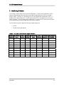
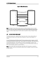
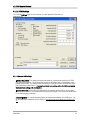
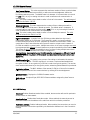
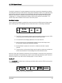
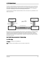
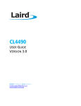
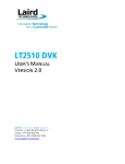
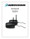
CL4790
Industrial 900MHz ConnexLink
User’s Manual
Version 1.0
11160 THOMPSON AVENUE
LENEXA, KS 66215
(800) 492-2320
www.aerocomm.com
[email protected]
Document Information
Copyright
Information
Copyright © 2004 AEROCOMM, Inc. All rights reserved.
The information contained in this manual and the accompanying
software programs are copyrighted and all rights are reserved by
AEROCOMM, Inc. AEROCOMM, Inc. reserves the right to make
periodic modifications of this product without obligation to notify
any person or entity of such revision. Copying, duplicating, selling, or otherwise
distributing any part of this product without the prior consent of an authorized
representative of AEROCOMM, Inc. is prohibited.
All brands and product names in this publication are registered
trademarks or trademarks of their respective holders.
This material is preliminary
Information furnished by AEROCOMM in this specification is believed to be accurate. Devices sold
by AEROCOMM are covered by the warranty and patent indemnification provisions appearing in its
Terms of Sale only. AEROCOMM makes no warranty, express, statutory, and implied or by
description, regarding the information set forth herein. AEROCOMM reserves the right to change
specifications at any time and without notice.
AEROCOMM products are intended for use in normal commercial applications. Applications
requiring extended temperature range or unusual environmental requirements such as military,
medical life-support or life-sustaining equipment are specifically not recommended without
additional testing for such application.
Limited Warranty
For a period of one (1) year from the date of purchase, AEROCOMM warrants the transceiver
against defects in materials and workmanship. AEROCOMM will not honor this warranty (and this
warranty will be automatically void) if there has been any:
(1) Tampering, signs of tampering, or opening the transceiver’s case.
(2) Use of AC power adapters and cables other than those originally supplied with the
transceivers.
(3) Repair or attempt to repair by anyone other than an AEROCOMM authorized
technician.
This warranty does not cover and AEROCOMM will not be liable for, any damage or failure caused
by misuse, abuse, acts of God, accidents, electrical irregularity, or other causes beyond
AEROCOMM control, or claim by other than the original purchaser.
6/24/2005
2
FCC Information
FCC Notice
WARNING: This device complies with Part 15 of the FCC Rules. Operation is subject to
the following two conditions: (1) This device may not cause harmful
interference and (2) This device must accept any interference received,
including interference that may cause undesired operation.
RF Exposure/Installation Instructions
WARNING: To satisfy FCC RF exposure requirements for mobile transmitting devices,
this equipment must be professionally installed such that the end user is
prevented from replacing the antenna with a non-approved antenna. The
end user should also be prevented from being within 20cm of the antenna
during normal use with the exception of hands, feet, wrists and ankles.
The preceding statement must be included as a CAUTION statement in
manuals for OEM products to alert users on FCC RF Exposure compliance.
Caution: Any change or modification not expressly approved by
AeroComm could void the user’s authority to operate the equipment.
6/24/2005
3
Table of Contents
USER’S MANUAL ........................................................................................... 1
FIGURES .............................................................................................................................. 4
TABLES ................................................................................................................................ 4
1. CL4790 RF TRANSCEIVER....................................................................................... 5
1.1
1.2
1.3
2.
OVERVIEW ........................................................................................................... 5
CL4790 SPECIFICATION ....................................................................................... 6
CL4790 INTERFACE ............................................................................................. 7
INTERFACING PROTOCOL .............................................................................. 10
2.1
2.2
2.3
RS-232............................................................................................................... 11
RS-485 (2-WIRE HALF DUPLEX) ........................................................................ 12
HARDWARE FLOW CONTROL ............................................................................. 13
3. NETWORK TOPOLOGIES..................................................................................... 14
3.1 POINT-TO-POINT ...................................................................................................... 14
3.2 POINT-TO-MULTIPOINT ............................................................................................ 14
4. CL4790/CN4790 CONFIGURATION UTILITY SOFTWARE............................. 15
4.1 INSTALLATION.......................................................................................................... 15
4.2 CL4790/CN4790 SETTINGS ..................................................................................... 15
4.2.1 CL4790 Settings ............................................................................................... 16
4.2.2 CN4790 Settings............................................................................................... 22
5. TROUBLESHOOTING ............................................................................................ 28
Figures
Figure 1- RS-232/RS-485 CL4790 Front View.............................................................. 7
Figure 2- RS-232 CL4790 Back View ............................................................................ 8
Figure 3- RS-485 CL4790 Back View ............................................................................ 8
Figure 4- CL4790 Mechanical Diagram......................................................................... 9
Figure 5- RS-232 Male/Female Connector Pin out ................................................... 11
Figure 6- DCE to DTE Interface.................................................................................... 11
Figure 7- DCE to DCE Interface ................................................................................... 12
Figure 8- Point-to-Point Network.................................................................................. 14
Figure 9- Multiple Networks of Point-to-Multipoint CL4790s ................................... 14
Tables
Table 1 – DTE, DCE and Null Modem Signal Definitions......................................... 10
6/24/2005
4
CL4790 User’s Manual
1. CL4790 RF Transceiver
The CL4790 transceiver is a Frequency-Hopping Spread Spectrum (FHSS) radio designed for
license-free operation in the 900MHz ISM band. Out-of-the box, the radio sustains a standard
asynchronous serial data stream between two or more radios. Housed in a compact and rugged
die-cast enclosure, the radio is equipped to replace thousands of meters of serial cable with its
wireless link. The radio features an RS-232 or RS-485 interface for integration into legacy data
systems.
Features
Masterless: True peer-to-peer, each module can communicate with any other module
within its range.
API commands to control packet routing and acknowledgement on a packet-by-packet
basis
1.1
Durable Industrial grade enclosure
Transparent operation, supports any legacy system
Transmits around corners, through walls
Reliable communication up to 115.2Kbps
Point-to-Point and Point-to-Multipoint setups
Overview
The CL4790 uses Frequency Hopping Spread Spectrum modulation, where the units “hop” from
frequency to frequency many times per second using a specific hop pattern applied to all the
transceivers in the same network. A distinct hopping pattern is provided for each Channel
Number, thereby allowing multiple networks to co-exist in the same area without interference.
CL4790 transceivers operate in a Masterless architecture. The unique feature of this architecture
is its dynamic Session extension and Collision Avoidance mechanism, which uses a proprietary
scoring system to promote contention free communication and ensure that each node has fair
access to the network. This instinctive dynamic peer-to-peer networking architecture enables
several transceiver pairs to carry on simultaneous conversations on the same network.
CL4790s implement a proprietary communication protocol to provide secure data transmissions.
As it uses FHSS technology, the data remains reliable over long distances. Use of license free
frequency bands ensure that the units are ready to use with no further certification requirements.
Each unit is small and easily portable for use in mobile and temporary settings as well as for fixed
installations. The CL4790 configuration software enables custom configurations based on unique
application requirements.
6/24/2005
5
CL4790 User’s Manual
1.2
CL4790 Specification
Specifications
CL4790 - 1000
TRANSCEIVER PERFORMANCE
Output power
1000mW
Transmission range
Up to 1500 feet (450m) indoors; Up to 20 miles (32 km) line-of-sight
Data rate
Up to 115.2 Kbps
RF Data Rate
76.8kbps fixed
Receiver Sensitivity
-100dBm typical @ 76.8kbps RF Data Rate
Power Consumption (@ 12 Vdc)
400mA
Configuration software
Easy-to-use Windows based software
NETWORKING AND SECURITY
Frequency band, RF Technology
902 – 928, FHSS (USA); 915-928, FHSS (Australia)
Supported Network Topologies
Point-to-Point, Point-to-Multipoint
Channels
32
Security
One byte System ID. 56-bit DES encryption key.
ANTENNA
RF Connector
RPSMA Jack
Type
1/2 Wave Dipole
ELECTRICAL
Electrical requirements
Line voltage 100 – 120V (240V outside US);
Power supply
6-foot cable, AC power connector
ENVIRONMENTAL
Environmental conditions
Operating temperature -40° to +80°C; 10% to 90% humidity (non-condensing)
PHYSICAL
Dimensions
4.4 x 2.7 x 1.4 inches
Weight
6 oz (170 g)
Serial Connector
DB-9 Male (RS-232), Terminal Block (RS-485)
Serial Cord length
6 feet (183 cm)
6/24/2005
6
CL4790 User’s Manual
1.3
CL4790 Interface
The CL4790 supports RS-232/RS-485 (2-wire Half Duplex) protocols. By definition, RS-485
protocol can tolerate high noise and push signals over long cable lengths. When using cables,
RS-485 will communicate as far as 4000feet (1200m) and offer multi-drop capability where up to
32 nodes may be connected. RS-232 cables are suitable for distances less than 100 feet
(30.5m). AeroComm wireless solutions are not subject to the cabling restrictions for distance,
but either interface (RS-232 or RS-485) is available when ordering the CL4790s.
Figure 1- RS-232/RS-485 CL4790 Front View
Status LEDs
Pwr Link Rx
RPSMA Antenna Connector
Tx
CL4790 Status LEDs
LED
Color
Pwr
Green
Link
Red
Rx
Green
Tx
Red
6/24/2005
Description
On indicates that the unit is powered up.
On indicates the transceiver units are in range of one another.
When flashing, LED indicates CL4490 unit is receiving data.
When and flashing, LED indicates CL4490 unit is sending data.
7
CL4790 User’s Manual
RS-232 Pin Assignments
Figure 2- RS-232 CL4790 Back View
DB9 Male Connector
1
Power Connector
Pin
1
2
3
4
5
6
7
8
9
5
6
9
Description
DCD
TxD
RxD
DSR
GND
DTR
CTS
RTS
RI
RS-485 (2-wire Half Duplex) Terminal Block Pin Assignments
Figure 3- RS-485 CL4790 Back View
Terminal Block
Power Connector
1
6
Pin
Description
1 VCC (6V-18V)(1.3 A Required)
2 485- (485B)
3 No Connect
4 No Connect
5 485+ (485A)
6 GND
Note: Standard power is applied through the power connector. Alternative power is available via
the terminal block pins.
6/24/2005
8
CL4790 User’s Manual
CL4790 Mechanical Diagram
Figure 4- CL4790 Mechanical Diagram
1.170
Antenna Connector
SMA Jack, Reverse Polarity
0.538
0.536
0.060
0.000
Side View
Label Recess, 3.5w x 2.0h
0.150 dia. mounting holes
(4) places
2.750
2.375
2.000
J3
9 Pin Male D-Connector
Tx
Status LEDs
J4
Pwr Link Rx
Power Jack w/ 0.100 dia. pin and
0.250 opening, pin is PWR.
0.375
0.000
4.750
4.500
4.185
0.565
0.250
0.000
Top View
Note: All dimension in inches unless noted
6/24/2005
9
CL4790 User’s Manual
2. Interfacing Protocol
The CL4790 is a DCE (Data Communications Equipment). A DCE can be interfaced to a DTE
using a straight through serial cable (the serial cable provided with the CL4790 is a straight
through cable). Typically, PC’s are defined as a DTE and peripherals are defined as DCE. To
interface a DCE with another DCE, or a DTE with another DTE, a null modem (or a Crossover)
cable is required. The null modem simply swaps pins to convert a DCE to a DTE and vice-versa.
A null modem cable can be provided with the CL4790 on request.
The CL4790 transceivers support the following interface protocols
•
RS-232
•
RS-485 (2-wire) Half Duplex
Table 1 – DTE, DCE and Null Modem Signal Definitions
DCE Pin DCE Signal
DCE
Number
Name
Direction
DTE Pin
Number
DTE Signal
Name
DTE
Null Modem Null Modem
Direction Female DB9 Male DB9
1
DCD
O
1
DCD
I
1
NC
2
TXD
O
2
RXD
I
2
3
3
RXD
I
3
TXD
O
3
2
4
DTR
I
4
DTR
O
4
6
5
GND
5
GND
5
5
6
DSR
O
6
DSR
I
6
4
7
RTS
I
7
RTS
O
7
8
8
CTS
O
8
CTS
I
8
7
9
RI
O
9
RI
I
9
NC
6/24/2005
10
CL4790 User’s Manual
2.1
RS-232
RS-232 is a single ended data transmission protocol. The RS-232 signals are represented by
voltage levels with respect to a system common (power / logic ground). The "idle" state (MARK)
has the signal level negative with respect to common, and the "active" state (SPACE) has the
signal level positive with respect to common. RS-232 has numerous handshaking lines (primarily
used with modems), and also specifies a communications protocol.
Figure 5- RS-232 Male/Female Connector Pin out
RS-232 DB9 Female Connector
RS-232 DB9 Male Connector
Pin
1
2
3
4
5
6
7
8
9
Pin
NC
2
3
4
5
6
7
8
NC
Description
DCD
RxD
TxD
DTR
GND
DSR
RTS
CTS
RI
Description
DCD
TxD
RxD
DSR
GND
DTR
CTS
RTS
RI
Figure 6- DCE to DTE Interface
CL4790 Modem
OEM Host/PC
CTS
CTS
RTS
RTS
RXD
TXD
TXD
RXD
GND
GND
DCD
DCD
DSR
DSR
DTR
DTR
DCE
DTE
Straight Through Cable
6/24/2005
11
CL4790 User’s Manual
Figure 7- DCE to DCE Interface
CL4790 Modem
OEM Host
CTS
CTS
RTS
RTS
RXD
TXD
TXD
RXD
GND
GND
DCD
NC
NC
DCD
DSR
DSR
DTR
DTR
RI
NC
NC
RI
DCE
DCE
Crossover Cable
Note: The Straight Through Cable provided with the CL4790 has female connectors on both
ends and the Crossover cable has a male connector at one end and a female connector at the
other end. Please use a male-to-male adapter or female-to-female adapter wherever required.
Using a null modem adapter with a Crossover cable is equivalent to using a Straight Through
cable.
2.2
RS-485 (2-wire Half Duplex)
The RS-485 interface uses a Differential Data Transmission that can help nullify the effects of
ground shifts and induced noise signals that can appear as common mode voltages on a
network.
The CL4790 implements a RS-485 (2-wire Half Duplex) multi-drop interface. Typically, a RS-485
bus will consist of a master and several slaves. The nodes will have unique addresses and can
send addressed packets to specific nodes. Because the bus is half duplex, no two nodes should
try to talk at the same time. The CL4790 does not have a RS-485 address, therefore, it will
transmit all RS-485 traffic over the RF. Conversely, as soon as a CL4790 receives a packet over
the RF, it will transmit the packet over the RS-485 bus.
Note: When using RS-485 (2-wire Half Duplex), a RS-485 to RS-232 converter is required to
configure the unit. AeroComm recommends a B&B Electronics 4WSD9R converter to translate
RS-485 to RS-232.
6/24/2005
12
CL4790 User’s Manual
2.3
Hardware Flow Control
Flow control refers to the control of data flow between the host and the CL4790. It is the
method used to handle data in the transmit/receive buffer of the CL4790 interface, and
determines how data flow between the host and the CL4790 is throttled. Often, in serial
communication, one device is capable of sending data much faster than the other can
receive. Flow control allows the slower device to tell the faster device to pause and resume
data transmission. (Flow control CTS and RTS are used by the CL4790 and its Host, locally
– NOT over the air. Therefore, one CL4790 cannot tell the other to slow down or speed up
as is mentioned above in the paragraph.)
When the RTS Enable option is selected on the Configuration Utility, the transceivers use
hardware flow control to regulate data flow. While using hardware flow control, the
transceiver that is ready to receive data sends a Clear To Send signal to its host (or the
device it is connected to). On the other hand, when a transceiver has something it wants to
send to its host, it checks the state of Ready To Send and if it is logic low, will send data to its
host. If RTS is logic high, it will not send data to its host. These signals are sent apart from
the data itself on separate wires. Note: CTS is always enabled by default. RS-485 Interface
does not support Hardware flow control.
6/24/2005
13
CL4790 User’s Manual
3. Network Topologies
Topology refers to the shape of a network, or the network's layout. How different nodes in a
network are connected to each other and how they communicate, is determined by the network's
topology. The CL4790s support a Point-to-Point and a Point-to-Multipoint network topology.
3.1 Point-to-Point
A point-to-point system is a simple arrangement consisting of just two CL4790s. Sometimes
referred to as a wireless bridge, a point-to-point link replaces a single communications cable. A
point-to-point link might be used to connect a PLC to a remote monitoring station.
Figure 8- Point-to-Point Network
OEM HOST
(Remote Monitoring
Station)
CL4790
CL4790
OEM HOST
(PLC)
3.2 Point-to-Multipoint
Point-to-Multipoint systems have one base station, or access point, that controls communications
with all of the other wireless nodes in the network. This allows for the creation of a wireless
network consisting of multiple nodes. By programming each CL4790 with a network specific
Channel Number and System ID multiple networks can be created see (Fig 9).
Figure 9- Multiple Networks of Point-to-Multipoint CL4790s
Example: Channel Number = 13
System ID = 123
6/24/2005
Example: Channel Number = 25
System ID = 256
14
CL4790 User’s Manual
4. CL4790/CN4790 Configuration Utility Software
AeroComm provides the easy to use CL4790/CN4790 Utility Software for programming the
CL4790/CN4790. The GUI based software does not require any hardware configuration and
works by itself. The software is compatible with Microsoft® Windows 95, 98, 2000, Me, NT and
XP. CL4790/CN4790s are plug-and-play devices that work with minimal or no configuration.
However, users may refer to the AC4790 manual for details about the radio’s operation and
advanced configuration commands. The SDK Software can be used to evaluate the advanced
configuration commands. The SDK Software and AC4790 manual can be found on the Connex
Tools and Literature CD or on our website at http://www.aerocomm.com/.
Note: The users should refer to the ConnexNet manual for details about the CN4790 interface.
4.1 Installation
1.
Locate the CL4790 Configuration Utility, 900 MHz link in the Software section on the Connex
Tools & Literature CD. This software is also available at
http://www.aerocomm.com/Software/Driver_CL4790_900Mhz_v.1.zip.
2. When prompted, accept the default directory or change to the desired directory where
the program files will be installed.
3. When finished, a window will be displayed indicating a successful installation. Select
OK.
4.2 CL4790/CN4790 Settings
The configuration utility can be used to configure both CL4790 and CN4790. The configuration
utility defaults to CL4790 configuration when it is loaded; it can be used to configure the CN4790
by checking the CN4790 check box on the configuration page.
6/24/2005
15
CL4790 User’s Manual
4.2.1 CL4790 Settings
The CL4790 Settings Page is shown below, as it will appear the first time the
program is run.
4.2.1.1 ConnexLink Settings
Interface Baud Rate: This defines the baud rate used for communicating with the CL4790
over the serial interface. The RF baud rate is fixed at 76.8 Kbps and is independent of the
Interface Baud Rate. The default baud rate setting is 57600 bps unless the units have been
pre-configured by AeroComm. The Interface Baud Rate setting of the CL4790 must match
the Baud Rate setting of its host device.
Random Back Off: Random BackOff determines the random amount of time a transceiver
waits when a collision occurs before resending the packet again. The amount of randomness
is controlled by this parameter.
Channel Number: A number that designates an independent network of CL4790 units. Up
to 32 independent networks can be created. The valid range of values for this field is 16 to
47.
6/24/2005
16
CL4790 User’s Manual
Max Transmit Retries: This value represents the maximum number of times a particular data
packet will be transmitted unsuccessfully, or without an acknowledgement, before the
CL4790 discards the packet. The default value is 4 attempts. If communication is lost and
the Link LED is on, try increasing this value in small increments until communication is
reestablished.
Note: This value is always associated to radios in Point to Point network. The valid range of
values for this field is 2 to 255.
Broadcast Attempts: This value represents the number of times a data packet will be
transmitted by the CL4790 when in Broadcast mode. The default value is 4 attempts. If
communication is lost and the receiving radio’s Link LED is on, try increasing this value in
small increments until communication is reestablished.
Note: This value is always associated to radios in Point-to-Multipoint network. The valid
range of values for this field is 2 to 255.
System Identification: A number from 0 to 256 that provides added security to each
independent network of CL4790 units. The System ID is used in conjunction with the
Channel Number and serves as an RF password to maintain secure transfers of data. The
combination of the Channel Number and System ID must be unique to each network of
CL4790s to establish communication. Multiple transceivers in the same coverage area must
be programmed with different Channel Numbers to prevent inoperability of the networks.
The System ID will not prevent inoperability that occurs from locating multiple transceivers
with the same Channel Number in the same coverage area.
Important Note: Separate Collocated CL4790 networks must operate on different Channel
Numbers. All units in a given CL4790 network must have identical Channel Numbers and
System IDs.
Data Encryption Key: Encryption is the process of encoding an information bit stream to
secure the data content. The DES algorithm is a common, simple and well-established
encryption routine. An encryption key of 56 bits is used to encrypt the packet. The receiver
must use the exact same key to decrypt the packet; otherwise garbled data will be produced.
Destination Address: The MAC Address of the remote CL4790 in a Point-to-Point network.
Used to optimize Point-to-Point communications by utilizing RF Acknowledgement.
Firmware Version: Displays the CL4790’s firmware version.
MAC Address: A unique 6 Byte, IEEE 802.3 Ethernet address assigned by AeroComm to
each CL4790.
4.2.1.2 RF Delivery
Broadcast: Enables Broadcast mode. When enabled, the transceiver will send its packets to
all transceivers on that network.
Auto Destination: Enables Auto Destination mode. When enabled, the transceiver sets its
destination address to the address of the radio from which it received a packet first.
Destination Address: Enables Addressed mode. When enabled, the transceiver can send or
receive data from a transceiver specified by the Destination Address box in the ConnexLink
Settings.
6/24/2005
17
CL4790 User’s Manual
4.2.1.3 Optional Settings
Data Encryption: Enables the Data Encryption Key. All CL4790s in the same network must
have the same encryption setting.
RTS Enable: Enables the Request To Send control line. When enabled, enables Hardware
Flow Control. Refer to Section 2.3 Hardware Flow Control.
Parity: Needs to be enabled if host requires even or odd parity and 8 data bits. This is
considered as 9-bit mode. Note: Enabling Parity cuts the overall throughput into half.
Full Duplex: This mode the transceivers intelligently shares the bandwidth to enable Full
Duplex. Though the RF hardware is still technically half duplex, it makes the transceiver
seem full duplex. This can cause overall throughputs to be cut in half. Note: All transceivers
on the same network must have the same setting for Full Duplex.
Modem Mode: Full modem handshaking is supported by the transceivers when Modem
Mode is enabled. Modem Mode is incompatible with RS-485Interface. Enables DCD, DTR,
DSR and Ring Indicator control lines.
Ignore Broadcast: When enabled, a transceiver ignores all the broadcast packet it receives.
4.2.1.4 API Mode
API Control is a powerful feature that the Masterless Protocol offers. When enabled, the Transmit
API, Send Data Complete and Receive API features provide dynamic packet routing and packet
accounting ability to the OEM Host, thereby eliminating the need for extensive programming on
the OEM Host side. This ability of the protocol makes it ideal for any legacy system.
Transmit API
When Transmit API is enabled, the OEM Host should use the following format to transmit a
packet over the RF.
81h
Payload Data
Length
Session
Count
(1- 80h)
Refresh
Transmit
Destination
Retries/Broadcast
MAC (2,1,0)
Attempts
Payload Data
1) If the OEM Host does not encode the header correctly, the transceiver will send
the entire string (up to 80h bytes) and will look for the header in the next data.
2) Although the 7 bytes of overhead are not sent over the RF, they are kept in the
buffer until the packet is sent. Keep this in mind so as to not overrun the 256byte buffer.
3) Setting MAC to FFh FFh FFh will broadcast the packets.
6/24/2005
18
CL4790 User’s Manual
Consider the example of a remote temperature monitoring system where temperature readings
are obtained from sensors attached to the transceivers at remote locations. This application may
require polling each and every transceiver individually and obtaining the temperature reading.
When the Transmit API is enabled the packets are dynamically routed with out requiring any
configuration i.e. change the destination address every time the packet is transmitted. This
makes it easy when hundreds of transceivers need to be polled.
Send Data Complete
When Send Data Complete is enabled, the transceiver sends the OEM Host the following data
upon receiving an RF Acknowledge from the remote transceiver or exhausting all attempts.
00h: Failure
82h
RSSI
RSSI *
01h: Success
1) The RSSI is how strong the remote transceiver heard the local transceiver, RSSI*
is how strong the local transceiver heard the remote transceiver.
2) Successful RF Acknowledge updates the Success/Failure bit.
3) When the transceiver is transmitting Broadcast Packets it will always return
success after exhausting all Broadcast Attempts.
4) API Send Data Complete can be used as a software send data complete
indicator
5) The transceiver could receive a failure even though the packet was received as it
could have missed the RF Acknowledge from the remote transceiver.
When the Send Data Complete is enabled an RF Acknowledge is received for every packet that
has been transmitted. This would be very useful in cases where the information sent is vital and
OEM Host needs to retry and send the message again in case of a failure.
Receive API
When Receive API is enabled; upon receiving a packet the radio sends its OEM Host the packet
in the following format.
81h
Payload Data
Length
RSSI
RSSI*
Destination
MAC (2,1,0)
Payload Data
The RSSI is how strong the remote transceiver heard the local transceiver, RSSI* is how strong the
local transceiver heard the remote transceiver.
6/24/2005
19
CL4790 User’s Manual
Consider a remote temperature monitoring system where the transceivers have to transmit their
temperature reading periodically. When the Receive API is enabled every data packet received
has also the information about the transceiver that transmitted the packet. This information is
very useful in identifying the transceiver and analyzing its wireless link.
The Transmit API, Send Data Complete and Receive API can be used in any combination to suit
different applications.
OEM Host
OEM Host
Send Data
Complete
Receive
API
packet
Transmit API
packet
RF Transmit Packet
Local Transceiver
RF Acknowledge
Remote Transceiver
Note: When both Send Data Complete and Receive API on the API Mode is enabled Send Data
Complete is to be received before the transceiver gets a Receive API packet (i.e. receives
another packet before it gets an acknowledge for a packet sent). However this order may get
reversed when the Send Data Complete packet is missed and is being resent after the Receive
API packet is received.
Note: The API Mode over writes all the RF Delivery settings.
4.2.1.5 PC Settings
Port: Serial communications port of the PC connected to the CL4790 unit.
Baud Rate: Must equal the Interface Baud Rate setting of the CL4790 unit that is about to be
programmed.
6/24/2005
20
CL4790 User’s Manual
4.2.1.6 Programming the CL4790 units
1. Connect a CL4790 unit to the serial communications port on the PC.
2. Connect the power supply to the CL4790 unit. Make sure the Pwr LED is on.
3. Start the CL4790 Configuration Utility.
4. Select the COM Port that is connected to the CL4790 unit on the PC Settings section.
5. Select the Interface Baud Rate of the CL4790 unit. All CL4790 units are shipped with a
default rate of 57600 (unless units have been pre-configured to match specific serial
settings). If the Interface Baud Rate of the CL4790 unit is changed as described in
Section 4.2 Changing CL4790 Settings, then PC Setting Baud Rate must be set to the
same Baud Rate to allow proper programming of the units.
6. Select Read Radio to display the current settings of the CL4790 unit.
7. Change desired settings.
8. After all changes have been made, select Write Radio to save the changes.
9. Cycle Power to the unit after all changes has been saved. This will set the CL4790 unit to
its normal mode of operation.
6/24/2005
21
CL4790 User’s Manual
4.2.2 CN4790 Settings
The CN4790 Settings Page is shown below, as it will appear the first time the CN4790 check box
is checked.
4.2.2.1 ConnexLink Settings
Random Back Off: Random BackOff determines the random amount of time a transceiver
waits when a collision occurs before resending the packet again. The amount of randomness
is controlled by this parameter.
Channel Number: A number that designates an independent network of CN4790 units. Up
to 32 independent networks can be created. The valid range of values for this field is 16 to
47.
Max Transmit Retries: This value represents the maximum number of times a particular data
packet will be transmitted unsuccessfully, or without an acknowledgement, before the
CN4790 discards the packet. The default value is 4 attempts. If communication is lost and
the Link LED is on, try increasing this value in small increments until communication is
reestablished.
Note: This value is always associated to radios in Point to Point network. The valid range of
values for this field is 2 to 255.
6/24/2005
22
CL4790 User’s Manual
Broadcast Attempts: This value represents the number of times a data packet will be
transmitted by the CN4790 when in Broadcast mode. The default value is 4 attempts. If
communication is lost and the receiving radio’s Link LED is on, try increasing this value in
small increments until communication is reestablished.
Note: This value is always associated to radios in Point-to-Multipoint network. The valid
range of values for this field is 2 to 255.
System Identification: A number from 0 to 256 that provides added security to each
independent network of CN4790 units. The System ID is used in conjunction with the
Channel Number and serves as an RF password to maintain secure transfers of data. The
combination of the Channel Number and System ID must be unique to each network of
CN4790s to establish communication. Multiple transceivers in the same coverage area must
be programmed with different Channel Numbers to prevent inoperability of the networks.
The System ID will not prevent inoperability that occurs from locating multiple transceivers
with the same Channel Number in the same coverage area.
Important Note: Separate Collocated CN4790 networks must operate on different Channel
Numbers. All units in a given CN4790 network must have identical Channel Numbers and
System IDs.
Data Encryption Key: Encryption is the process of encoding an information bit stream to
secure the data content. The DES algorithm is a common, simple and well-established
encryption routine. An encryption key of 56 bits is used to encrypt the packet. The receiver
must use the exact same key to decrypt the packet; otherwise garbled data will be produced.
Destination Address: The MAC Address of the remote CN4790 in a Point-to-Point network.
Used to optimize Point-to-Point communications by utilizing RF Acknowledgement.
Firmware Version: Displays the CN4790’s firmware version.
MAC Address: A unique 6 Byte, IEEE 802.3 Ethernet address assigned by AeroComm to
each CN4790.
4.2.2.2 RF Delivery
Broadcast: Enables Broadcast mode. When enabled, the transceiver will send its packets to
all transceivers on that network.
Auto Destination: Enables Auto Destination mode. When enabled, the transceiver sets its
destination address to the address of the radio from which it received a packet first.
Destination Address: Enables Addressed mode. When enabled, the transceiver can send or
receive data from a transceiver specified by the Destination Address box in the ConnexLink
Settings.
6/24/2005
23
CL4790 User’s Manual
4.2.2.3 Optional Settings
Data Encryption: Enables the Data Encryption Key. All CN4790s in the same network must
have the same encryption setting.
Parity: Needs to be enabled if host requires even or odd parity and 8 data bits. This is
considered as 9-bit mode. Note: Enabling Parity cuts the overall throughput into half.
Full Duplex: This mode the transceivers intelligently shares the bandwidth to enable Full
Duplex. Though the RF hardware is still technically half duplex, it makes the transceiver
seem full duplex. This can cause overall throughputs to be cut in half. Note: All transceivers
on the same network must have the same setting for Full Duplex.
Modem Mode: Full modem handshaking is supported by the transceivers when Modem
Mode is enabled. Modem Mode is incompatible with RS-485Interface. Enables DCD, DTR,
DSR and Ring Indicator control lines.
Ignore Broadcast: When enabled, a transceiver ignores all the broadcast packet it receives.
4.2.2.4 API Mode
API Control is a powerful feature that the Masterless Protocol offers. When enabled, the Transmit
API, Send Data Complete and Receive API features provide dynamic packet routing and packet
accounting ability to the OEM Host, thereby eliminating the need for extensive programming on
the OEM Host side. This ability of the protocol makes it ideal for any legacy system.
Transmit API
When Transmit API is enabled, the OEM Host should use the following format to transmit a
packet over the RF.
81h
Payload Data
Length
Session
Count
(1- 80h)
Refresh
Transmit
Destination
Retries/Broadcast
MAC (2,1,0)
Attempts
Payload Data
1) If the OEM Host does not encode the header correctly, the transceiver will send
the entire string (up to 80h bytes) and will look for the header in the next data.
2) Although the 7 bytes of overhead are not sent over the RF, they are kept in the
buffer until the packet is sent. Keep this in mind so as to not overrun the 256-byte
buffer.
3) Setting MAC to FFh FFh FFh will broadcast the packets.
6/24/2005
24
CL4790 User’s Manual
Consider the example of a remote temperature monitoring system where temperature readings
are obtained from sensors attached to the transceivers at remote locations. This application may
require polling each and every transceiver individually and obtaining the temperature reading.
When the Transmit API is enabled the packets are dynamically routed with out requiring any
configuration i.e. change the destination address every time the packet is transmitted. This
makes it easy when hundreds of transceivers need to be polled.
Send Data Complete
When Send Data Complete is enabled, the transceiver sends the OEM Host the following data
upon receiving an RF Acknowledge from the remote transceiver or exhausting all attempts.
00h: Failure
82h
RSSI
RSSI *
01h: Success
1) The RSSI is how strong the remote transceiver heard the local transceiver, RSSI*
is how strong the local transceiver heard the remote transceiver.
2) Successful RF Acknowledge updates the Success/Failure bit.
3) When the transceiver is transmitting Broadcast Packets it will always return
success after exhausting all Broadcast Attempts.
4) API Send Data Complete can be used as a software send data complete
indicator
5) The transceiver could receive a failure even though the packet was received as it
could have missed the RF Acknowledge from the remote transceiver.
When the Send Data Complete is enabled an RF Acknowledge is received for every packet that
has been transmitted. This would be very useful in cases where the information sent is vital and
OEM Host needs to retry and send the message again in case of a failure.
Receive API
When Receive API is enabled; upon receiving a packet the radio sends its OEM Host the packet
in the following format.
81h
Payload Data
Length
RSSI
RSSI*
Destination
MAC (2,1,0)
Payload Data
The RSSI is how strong the remote transceiver heard the local transceiver, RSSI* is how strong the
local transceiver heard the remote transceiver.
6/24/2005
25
CL4790 User’s Manual
Consider a remote temperature monitoring system where the transceivers have to transmit their
temperature reading periodically. When the Receive API is enabled every data packet received
has also the information about the transceiver that transmitted the packet. This information is
very useful in identifying the transceiver and analyzing its wireless link.
The Transmit API, Send Data Complete and Receive API can be used in any combination to suit
different applications.
OEM Host
OEM Host
Send Data
Complete
Receive
API
packet
Transmit API
packet
RF Transmit Packet
Local Transceiver
RF Acknowledge
Remote Transceiver
Note: When both Send Data Complete and Receive API on the API Mode is enabled Send Data
Complete is to be received before the transceiver gets a Receive API packet (i.e. receives
another packet before it gets an acknowledge for a packet sent). However this order may get
reversed when the Send Data Complete packet is missed and is being resent after the Receive
API packet is received.
Note: The API Mode over writes all the RF Delivery settings.
4.2.2.5 PC Settings
IP Address: IP Address of the CN4490 unit.
Port: Port number of the CN4490 unit, the Port number is always 2101.
6/24/2005
26
CL4790 User’s Manual
4.2.2.6 Programming the CN4790 units
1. Connect a CN4790 unit to the serial communications port on the PC.
2. Connect the power supply to the CN4790 unit. Make sure the Pwr LED is on.
3. Start the CN4790 Configuration Utility.
4. Select the COM Port that is connected to the CN4790 unit on the PC Settings section.
5. Select the Interface Baud Rate of the CN4790 unit. All CN4790 units are shipped with a
default rate of 57600 (unless units have been pre-configured to match specific serial
settings). If the Interface Baud Rate of the CN4790 unit is changed as described in
Section 4.2 Changing CN4790 Settings, then PC Setting Baud Rate must be set to the
same Baud Rate to allow proper programming of the units.
6. Select Read Radio to display the current settings of the CN4790 unit.
7. Change desired settings.
8. After all changes have been made, select Write Radio to save the changes.
9. Cycle Power to the unit after all changes has been saved. This will set the CN4790 unit
to its normal mode of operation.
6/24/2005
27
CL4790 User’s Manual
5. Troubleshooting
Solution
Problem
CL4790
Read Radio
1. Make sure the PC Settings are right. See Section
displays error
4.2.3 PC Settings.
message: “Radio
not responding.”
2. Make sure the CL4790 unit uses the right serial
cable. Refer to Section 2.1 RS-232.
3.
If any other program that is using the same
COM port as CL4790 is open, close that
program and try to read the radio again.
4.
Reset the radio by cycling power after each
unsuccessful Read.
CN4790
1. Make sure the PC Settings are right. See
Section 7.2.3 PC Settings.
2. Make sure the CN4790 unit uses the
right Ethernet cable. Refer to Section 2.2
LAN Port.
3. If any other program that is using the
same LAN port as CN4790 is open, close
that program and try to read the radio again.
4. Reset the radio by cycling power after
each unsuccessful Read.
Write Radio
displays error
message: “Radio
not responding.”
1.
Cycle power to the radio.
1. Cycle power to the radio.
2.
Read the radio and make desired changes
and then Write the radio.
2. Read the radio and make desired
changes and then Write the radio.
Garbled Data
received.
1.
Check Data Encryption Standard settings.
1. Check Data Encryption Standard
settings.
Client’s Link LED
does not come
on.
1.
Make sure the unit is connected to power.
1. Make sure Server CN4790 unit is
powered up.
2.
Cycle power to the radio.
Link LED is on,
but data does
not get
transmitted or
received.
2.
Cycle power to the radio.
1.
Make sure the CL4790 unit(s) is connected to
the correct COM Port.
1. Make sure the CN4790 unit(s) IP
Address is right.
2.
Check the COM port settings for correct Baud
Rate, Parity and either Hardware or No Flow
Control. Units can have transmission errors
with Flow Control set to Xon/Xoff.
2. Try increasing the Maximum Transmit
Attempts (for Clients) and/or Broadcast
Attempts (for Servers) values in small
increments until communication is
established.
3.
Try increasing the Maximum Transmit Attempts
(for Clients) and/or Broadcast Attempts (for
Servers) values in small increments until
communication is established.
4.
Connect a Null Modem adapter between the
Client and its host device.
5.
Check the Destination Address setting.
3.
Check the Destination Address setting.
If these troubleshooting tips do not resolve the problem, please call our toll free number at
(800) 492-2320, extension 207. Technical support hours are Monday through Friday, 8:00 am to
5:00 pm Central Standard Time.
6/24/2005
28