1
Fujitsu Microelectronics (Shanghai) Co., Ltd.
Application Note
MCU-AN-500080-E-10
F²MC-8FX FAMILY
8-BIT MICROCONTROLLER
MB95F430 SERIES
Operational Amplifier
APPLICATION NOTE
Operational Amplifier Version 1.0
Revision History
Revision History
Date
2010-03-22
Author
Folix
Change of Records
V1.0, First draft
This manual contains 18 pages.
1.
The products described in this manual and the specifications thereof may be changed without prior notice.
To obtain up-to-date information and/or specifications, contact your Fujitsu sales representative or Fujitsu
authorized dealer.
2.
Fujitsu will not be liable for infringement of copyright, industrial property right, or other rights of a third party
caused by the use of information or drawings described in this manual.
3.
The contents of this manual may not be transferred or copied without the express permission of Fujitsu.
4.
The products contained in this manual are not intended for use with equipment which require extremely
high reliability such as aerospace equipments, undersea repeaters, nuclear control systems or medical
equipments for life support.
5.
Some of the products described in this manual may be strategic materials (or special technology) as
defined by the Foreign Exchange and Foreign Trade Control Law. In such cases, the products or portions
thereof must not be exported without permission as defined under the law.
© 2010 Fujitsu Microelectronics (Shanghai) Co., Ltd
MCU-AN-500080-E-10 - Page 2
Operational Amplifier Version 1.0
Table of Contents
Table of Contents
Revision History .............................................................................................................2
Table of Contents ...........................................................................................................3
1 Introduction ..............................................................................................................4
2 Amplifier Overview ...................................................................................................5
2.1 Block Diagram of Operational Amplifier ..........................................................6
2.2 Pins of Operational Amplifier ..........................................................................6
2.3 OPAMP Control Register................................................................................7
3 Operations of Operational Amplifier .........................................................................9
4 Amplifier setting procedure ....................................................................................10
5 Amplifier Driver ......................................................................................................11
5.1 Peripheral Usage ..........................................................................................11
5.2 Driver Code ..................................................................................................11
5.2.1 General Definition .................................................................................11
5.2.2 Amplifier Routine ..................................................................................12
6 Typical Application .................................................................................................13
6.1 HW Design ...................................................................................................13
6.2 Sample Code................................................................................................13
7 More Information....................................................................................................14
8 Appendix ................................................................................................................15
9 Sample Code .........................................................................................................16
MCU-AN-500080-E-10- Page 3
Operational Amplifier Version 1.0
Chapter 1 Introduction
1 Introduction
This application note introduces how to use the amplifier function on MB95F430 series.
Chapter 2 is an overview of operational amplifier.
Chapter 3 introduces the operations of operational amplifier.
Chapter 4 introduces the setting procedure of operational amplifier.
Chapter 5 introduces amplifier drivers.
Chapter 6 introduces the amplifier application demo.
MCU-AN-500080-E-10 - Page 4
Operational Amplifier Version 1.0
Chapter 2 Amplifier Overview
2 Amplifier Overview
The operational amplifier can be used to sense the ground current, and support
front-end analog signal conditioning prior to A/D conversion. It can operate in either
closed loop mode or standalone open loop mode.
■ Closed Loop Mode
The operational amplifier can be configured as a non-inverting closed loop operational
amplifier.
It has six closed loop gain options for ground current sensing, which can be selected by
software according to different sense voltage values.
■ Standalone Open Loop Mode
In this mode, the operational amplifier input pins are connected to external signals
without any output feedback.
The standalone open loop mode is designed for users that can choose more flexible
gain using external resistors.
MCU-AN-500080-E-10- Page 5
Operational Amplifier Version 1.0
Chapter 2 Amplifier Overview
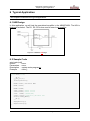
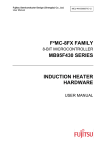
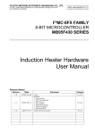
2.1
Block Diagram of Operational Amplifier
Figure 1. Block Diagram of Operational Amplifier
2.2
Pins of Operational Amplifier
The OPAMP uses the OPAMP_P pin and the OPAMP_N pin as the analog input pins of
the operational amplifier, and uses the OPAMP_O pin as the analog output pin of the
operational amplifier.
When GS[5] is set to "1B" and GS[4:0] are set to "00000B", the OPAMP will work as a
standalone open loop operational amplifier.
When GS[5] is set to "0B", the OPAMP will work as a non-inverting closed loop
operational amplifier. It provides six different closed loop gain settings through the
software.
MCU-AN-500080-E-10 - Page 6
Operational Amplifier Version 1.0
Chapter 2 Amplifier Overview
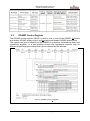
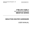
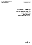
2.3
OPAMP Control Register
The OPAMP control register (OPCR) is used to turn on and off the OPAMP, to enable
and disable OPAMP analog output, and to enable and disable OPAMP analog input.
The register can also be used to set the OPAMP to operate as a standalone open loop
operational amplifier, or a non-inverting closed loop operational amplifier with six
different closed loop gain settings that can be selected by the software.
Figure 2. OPAMP Control r/Register
MCU-AN-500080-E-10- Page 7
Operational Amplifier Version 1.0
Chapter 2 Amplifier Overview
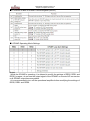
■ Functions of Bits in OPAMP Control Register (OPCR)
■ OPAMP Operating Mode Settings
Notes:
•While the OPAMP is operating, it is allowed to modify the settings of RES2, RES1 and
RES0, however, do not use the output signal of the OPAMP or execute A/D conversion
until OPAMP output becomes stable.
•It is recommended to turn off the operational amplifier before modifying the settings of
RES2, RES1 and RES0.
MCU-AN-500080-E-10 - Page 8
Operational Amplifier Version 1.0
Chapter 3 Operations of Operational Amplifier
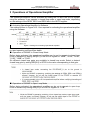
3 Operations of Operational Amplifier
The operational amplifier can be activated by setting the PD bit in the OPCR register
using the software. It can operate in closed loop mode or open loop mode, depending
on the settings of the RES2, RES1 and RES0 bits in the OPCR register.
■ Activating Operational Amplifier by Software
The settings shown in Figure 24.5-1 are required for activating the operational amplifier
using the software.
Figure 3. Settings for Activating Operational Amplifier
After the bits in the OPCR register are set as shown above, the operational amplifier will
not start operating until becomes stable.
■ Operations of OPAMP in Closed Loop Mode
Before being activated, the operational amplifier can be set to operate in closed loop
mode in advance by setting RES[2:0] in the OPCR register to "000B", "001B", "010B",
"011B", "100B" or "101B".
Six different closed loop gains are available in closed loop mode. Select a desired
closed loop gain by setting RES[2:0] in OPCR to the value corresponding to that gain.
■ Operations of OPAMP in Open Loop Mode
Before being activated, the operational amplifier can be set to operate in open loop
mode in advance by setting RES[2:0] in the OPCR register to "110B".
MCU-AN-500080-E-10- Page 9
Operational Amplifier Version 1.0
Chapter 4 Amplifier setting procedure
4 Amplifier setting procedure
Below is an example of procedure for setting the operational amplifier.
● Initial settings
1) Set both OPCR:OPID and OPCR:OPOD to "0" to enable both OPAMP analog input
and OPAMP analog output.
2) Set the feedback resistor and RES[2:0] in OPCR.
3) Set OPCR:PD to "0" to turn on the operational amplifier.
4) Wait until the operation amplifier becomes stable.
5) Start A/D conversion if necessary.
MCU-AN-500080-E-10 - Page 10
Operational Amplifier Version 1.0
Chapter 5 Amplifier Driver
5 Amplifier Driver
This is OPAMP driver description. /This chapter introduces OPAMP driver.
5.1 Peripheral Usage
The MCU pins are used as below:
OPAMP_N,used is used as amplifier negative input;
OPAMP_P,used is used as amplifier positive input;
OPAMP_O,used is used as amplifier output.
5.2 Driver Code
5.2.1 General Definition
typedef unsigned char
typedef unsigned char
typedef signed
char
typedef unsigned int
typedef signed
int
typedef unsigned long
typedef signed
long
#define BOOL
#define BYTE
#define UBYTE
#define WORD
#define UWORD
#define LONG
#define ULONG
#define UCHAR
#define UINT
#define DWORD
BOOLEAN;
INT8U;
INT8S;
INT16U;
INT16S;
INT32U;
INT32S;
/* Unsigned 8 bit quantity */
/* Signed
8 bit quantity */
/* Unsigned 16 bit quantity */
/* Signed
16 bit quantity */
/* Unsigned 32 bit quantity */
/* Signed
32 bit quantity */
BOOLEAN
INT8U
INT8U
INT16U
INT16U
INT32S
INT32U
INT8U
INT16U
INT32U
#define TRUE
#define FALSE
1
0
#define BYTE_LO(w)
#define BYTE_HI(w)
((UBYTE)(w))
((UBYTE)(((UWORD)(w)>>8)&0xFF))
MCU-AN-500080-E-10- Page 11
Operational Amplifier Version 1.0
Chapter 5 Amplifier Driver
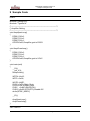
5.2.2 Amplifier Routine
void AmpOpenLoop()
Return
Parameters
Description
Example
: none.
: none.
: open-loop setting.
: AmpOpenLoop();
void AmpOpenLoop()
{
DDR6_P60=0;
DDR6_P61=0;
DDR6_P62=1;
OPCR=0x60;//Amplifier gain is R3/R1
}
void AmpCloseLoop()
Return
Parameters
Description
Example
: none.
: none.
: close-loop setting.
: AmpCloseLoop();
void AmpCloseLoop()
{
DDR6_P60=0;
DDR6_P61=0;
DDR6_P62=1;
OPCR=0x40;//Amplifier gain is 20V/V
}
MCU-AN-500080-E-10 - Page 12
Operational Amplifier Version 1.0
Chapter 6 Typical Application
6 Typical Application
This chapter introduces the ty[ical application.
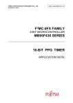
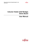
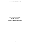
6.1 HW Design
In this application, we will test the operational amplifier in the MB95F430K. The HW is
designed as below. The R1, R2, R3 is /are used in open-loop amplifier.
Figure 4. Hardware d/Design
6.2 Sample Code
void main(void)
Return
: none.
Parameters : none;
Description : system main programm.
Example
: main();
void main(void)
{
__DI();
__set_il(3);
InitIrqLevels();
WDTH =0xA5;//Disable WTG
WDTL =0x96;
WATR =0xEE;
SYCC =0xF0;//Main Clock
SYCC2=0xF4;//Main Clock
SYSC =0xBC;//BUZZ(P01)
SYSC2 =0x02;//PPG(P73),Disable I2C
while(!STBC_MRDY);
__EI();
AmpOpenLoop();
AmpCloseLoop();
}
MCU-AN-500080-E-10- Page 13
Operational Amplifier Version 1.0
Chapter 7 More Information
7 More Information
For more information on FUJITSU MB95200 products, please visit following website:
English Version http://www.fujitsu.com/cn/fmc/en/services/mcu/mb95430/
Simplified Chinese Version http://www.fujitsu.com/cn/fmc/services/mcu/mb95430/
MCU-AN-500080-E-10 - Page 14
Operational Amplifier Version 1.0
Chapter 8 Appendix
8 Appendix
Figure 1. Block Diagram of Operational Amplifier ......................................................... 6
Figure 2. OPAMP Control register ................................................................................... 7
Figure 3. Settings for Activating Operational Amplifier ................................................ 9
Figure 4. Hardware design ............................................................................................. 13
MCU-AN-500080-E-10- Page 15
Operational Amplifier Version 1.0
Chapter 9 Sample Code
9 Sample Code
main.c
#include "mb95430.h"
#include "TypeDef.h"
/*---------------------------------------------------------------------------*/
/* Amplifier Setting
/*---------------------------------------------------------------------------*/
void AmpOpenLoop()
{
DDR6_P60=0;
DDR6_P61=0;
DDR6_P62=1;
OPCR=0x60;//Amplifier gain is R3/R1
}
void AmpCloseLoop()
{
DDR6_P60=0;
DDR6_P61=0;
DDR6_P62=1;
OPCR=0x40;//Amplifier gain is 20V/V
}
void main(void)
{
__DI();
__set_il(3);
InitIrqLevels();
WDTH =0xA5;
WDTL =0x96;
WATR =0xEE;
SYCC =0xF0;//Main Clock
SYCC2=0xF4;//Main Clock
SYSC =0xBC;//BUZZ(P01)
SYSC2 =0x02;//PPG(P73),Disable I2C
while(!STBC_MRDY);
__EI();
AmpOpenLoop();
AmpCloseLoop();
}
VECTORS.C
MCU-AN-500080-E-10 - Page 16
Operational Amplifier Version 1.0
Chapter 9 Sample Code
#include "mb95430.h"
void InitIrqLevels(void)
{
/* ILRx
IRQs defined by ILRx */
ILR0 = 0xFF;
// IRQ0:
// IRQ1:
// IRQ2:
// IRQ3:
external interrupt ch0 | ch4
external interrupt ch1 | ch5
external interrupt ch2 | ch6
external interrupt ch3 | ch7
ILR1 = 0xFF;
// IRQ4: UART/SIO ch0
// IRQ5: 8/16-bit timer ch0 (lower)
// IRQ6: 8/16-bit timer ch0 (upper)
// IRQ7: Output Compare ch0
ILR2 = 0xFF;
// IRQ8: Output Compare ch1
// IRQ9: none
// IRQ10: Voltage Compare ch0
// IRQ11: Voltage Compare ch1
ILR3 = 0xFF;
// IRQ12: Voltage Compare ch2
// IRQ13: Voltage Compare ch3
// IRQ14: 16-bit free run timer
// IRQ15: 16-bit PPG0
ILR4 = 0xFF;
// IRQ16: I2C ch0
// IRQ17: none
// IRQ18: 10-bit A/D-converter
// IRQ19: Timebase timer
ILR5 = 0xFF;
// IRQ20: Watch timer
// IRQ21: none
// IRQ22: none
// IRQ23: Flash Memory
}
/*--------------------------------------------------------------------------Prototypes
Add your own prototypes here. Each vector definition needs is prototype. Either do it here or include a header file containing them.
-----------------------------------------------------------------------------*/
__interrupt void DefaultIRQHandler(void);
/*--------------------------------------------------------------------------Vector definition
Use following statements to define vectors.
MCU-AN-500080-E-10- Page 17
Operational Amplifier Version 1.0
Chapter 9 Sample Code
All resource related vectors are predefined.
Remaining software interrupts can be added hereas well.
-----------------------------------------------------------------------------*/
#pragma intvect DefaultIRQHandler 0
// IRQ0: external interrupt ch0 | ch4
#pragma intvect DefaultIRQHandler 1
// IRQ1: external interrupt ch1 | ch5
#pragma intvect DefaultIRQHandler 2
// IRQ2: external interrupt ch2 | ch6
#pragma intvect DefaultIRQHandler 3
// IRQ3: external interrupt ch3 | ch7
#pragma intvect DefaultIRQHandler 4
#pragma intvect DefaultIRQHandler 5
#pragma intvect DefaultIRQHandler 6
#pragma intvect DefaultIRQHandler 7
// IRQ4: UART/SIO ch0
// IRQ5: 8/16-bit timer ch0 (lower)
// IRQ6: 8/16-bit timer ch0 (upper)
// IRQ7: Output Compare ch0
#pragma intvect DefaultIRQHandler 8
//
#pragma intvect DefaultIRQHandler 9
//
#pragma intvect DefaultIRQHandler 10 //
#pragma intvect DefaultIRQHandler 11 //
IRQ8: Output Compare ch1
IRQ9: none
IRQ10: Voltage Compare ch0
IRQ11: Voltage Compare ch1
#pragma intvect DefaultIRQHandler 12
#pragma intvect DefaultIRQHandler 13
#pragma intvect DefaultIRQHandler 14
#pragma intvect DefaultIRQHandler 15
//
//
//
//
IRQ12: Voltage Compare ch2
IRQ13: Voltage Compare ch3
IRQ14: 16-bit free run timer
IRQ15: 16-bit PPG0
#pragma intvect DefaultIRQHandler 16
#pragma intvect DefaultIRQHandler 17
#pragma intvect DefaultIRQHandler 18
#pragma intvect DefaultIRQHandler 19
//
//
//
//
IRQ16: I2C ch0
IRQ17: none
IRQ18: 10-bit A/D-converter
IRQ19: Timebase timer
#pragma intvect DefaultIRQHandler 20
#pragma intvect DefaultIRQHandler 21
#pragma intvect DefaultIRQHandler 22
#pragma intvect DefaultIRQHandler 23
//
//
//
//
IRQ20: Watch timer
IRQ21: none
IRQ22: none
IRQ23: Flash Memory
/*--------------------------------------------------------------------------DefaultIRQHandler()
This function is a placeholder for all vector definitions.
Either use your own placeholder or add necessary code here
(the real used resource interrupt handlers should be defined in the main.c).
-----------------------------------------------------------------------------*/
__interrupt void DefaultIRQHandler(void)
{
__DI();
// disable interrupts
while(1)
__wait_nop();
// halt system
}
MCU-AN-500080-E-10 - Page 18