1
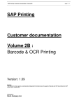
Assembly and Users Manual
506 and 5012
Print No. 29490999 / 47.98
20009305
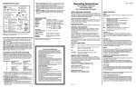
WARNING:
l Read the instructions booklet before using this product. l When using a folding combination
machine with bench and canopy, lie down on the bench and pull the canopy down until it will
move no further. When using a canopy only, lie down and pull the canopy down as for as the
stand will allow. l Operation of this device closer to the body than the recommended minimum
distance for use may result in overexposure. l Recommended eyewear: Provided eyeshields
(Intexco Nr. 5635/1s) or equivalent eyewear as defined under 21 CFR 1040.20 2(b) (6).
One pair of protective eyewear is furnished with this equipment and should be worn by all persons
in the room when lamps are on. Disconnect power cord before attempting to clean, replace lamps
or engage in the maintenance of this product. THE FOLLOWING LAMPS HAVE BEEN CERTIFIED
FOR USE IN THIS EQUIPMENT: Cosmolux RCS or VLR, Cosmolux VHR, DR. KERN 400 W
HP-lamp or compatible types.
THIS PRODUCT CONFORMS WITH PERFORMANCE STANDARDS FOR SUN LAMP
PRODUCTS UNDER 21 CFR PART 1040.20
DANGER
Ultraviolet radiation. Follow instructions. Avoid overexposure. As with natural sunlight, overexposure
can cause eye and skin injury and allergic reactions. Repeated exposure may cause premature
aging of the skin and skin cancer. WEAR PROTECTIVE EYEWEAR; FAILURE TO MAY RESULT
IN SERVERE BURNS OR LONG-THERM INJURY TO THE EYES.
Medication or cosmetics may increase your sensitivity to the ultraviolet radiation. Consult physician
before using sunlamp if you are using medications or have a history of skin problems or believe
yourself especially sensitive to sunlight. If you do not tan in the sun, you are unlikely to tan from
the use of this product. Minimum use distance is 1 inch or 2.54 centimeter. Tanning may appear
after one application provided that your skin is capable of developing a suntan. Allow 48 hours
between sessions to obtain a base tan, once or twice per week to maintain appearance.
2
Table of Contents
3
4
5
11
12
12
12
13
13
13
13
14
14
15
15
15
Important Notice
Things to know about Tanning
Assembly Instructions
Operating Instructions
Cleaning the Solarium
Adjusting the Spring Lifting System
Replacement of the facial tanning lamps and filter glass
Replacing the intake Filters
Main Hot Air Exhaust
Remote Timer and / or Coinbox Connection
Connection of auxiliary Fans
Replacement Components
Technical and Electrical Specifications
Warranty Information
Danger, Warning, Compliance and Identification Labels
Guarantee
Important Notices
l
l
l
l
l
l
l
l
This solarium is designed to permanently connected to a single phase 220 V 60 Hz power source.
This solarium may only be used in a dry area, free of liquid spray or high humidity (below 70 %). The ambient temperature should
not exceed 28 degrees Celsius(85 Degrees Fahrenheit), otherwise the surface temperature of the bench may become warm.
To prevent overheating of the solarium, air intake vents and fan output areas must not be blocked.
In the event of a ventilation fan failure, the solarium will operate warmer than normal, and should be shut down immediately to
repair or replace the fan.
Insure that the solarium is disconnected from the main power source when replacing lamps, starters, or acrylics, as well as during
maintenance or cleaning.
Electrical reparation may only be conducted by an authorized technician.
The floor surface upon which the solarium is to be placed must have a support rating of at least 150 Lb. per square foot. If the surface
rating cannot be officially confirmed, Dr. Kern USA must be contacted for further instructions prior to installation.
If the solarium is operated with 220 V single phase, only a power cord 3 x AWG 2 may be used. In case of connection to a 3phase
220 V power source the connection lead should be type SJT or equivalent 4 x AWG 4 cable. In both cases the maximum length should
not exceed 25 ft.
3
Important Things to know before Tanning
The irradiance output of this solarium has been calibrated for optimum effectiveness. Only the highest quality reflector lamps and
acrylic sheets are employed to provide the best possible tanning performance at maximum UV-transmission levels. The Te / Tm (Time
to Erythema relative to Time to Melanogenesis) has been precisely formulated and expressed in the recommended maximum exposure
schedule (MED), which should never be exceeded.
In both commercial and residential application, the user should consult his or her physician about indoor sun tanning and its effects on
their condition before using this solarium. Persons taking prescription medications must always take care that such substances do not
increase the level of sensitivity to UV light, and may not tan if any warnings are issued by their respective manufacturers or the
prescribing physician.
If you do not normally tan in natural sunlight, it is unlikely that a tan will occur through use of this solarium. Persons of skin type 1 (see
MED schedule) should not tan indoors, unless instructed to do so by a dermatologist. In that event, the commercial operator of the
solarium must obtain written permission from the users dermatologist before tanning.
For Commercial Operators:
1. No one under the age of 16 should be allowed to tan without the expresss, written consent of a parent or guardian.
2. The distance between the lamps and an individual tanning in this solarium has been preset, and may under no conditions be
altered or lessened.
3. If the remote timer controlling the session length of the solarium is not in proper working order, do not allow customers to use until
reparations have been made.
4. UV radiation can cause damage to the skin and eyes. Insure that you and your staff have been properly trained by a state or
provincially - authorized educational organization to give adequate usage instructions to tanning customers.
5. Obey the contents of the danger and warning labels affixed to the solarium, and do not attempt to override the MED (maximum
exposure dosage) session times.
6. Insure that all users of this solarium are given eye protection, of the type approved by your respective states or provinces health
and / or radiological control agency, and insist that they be at all times when the units lamps are lighted.
7. Instruct all users to remove any make-up or facial cosmetics before using the solarium.
8. Be sure to not allow any individual to tan more than once during the course of a 24 hour period.
9. Do not allow any individual to tan should they appear physically sick, disoriented, under the influence of alcohol, or display signs
of swollen or infected skin. Insist that any such person goes immediately to their physician if they complain of injuries or burned
skin before or after tanning.
10. Recommend to your customers that they apply a moisturizing lotion after tanning.
RECOMMENDED EXPOSURE
SCHEDULE
CLASS:
I
4
SKIN TYPES:
SENSITIVE SKIN
(Burns easily and severely, and does not tan.)
II
LIGHT SKIN
III
NORMAL SKIN
IV
DARK SKIN
(Burns easily and severely, and tans minimally.)
(Burns moderately, and tans moderately.)
(Burns minimally, and tans well or above average.)
MAXIMUM EXPOSURE TIMES
(IN MINUTES)
week 1
week 2
week 3
MAX
TANNING NOT ADVISED
3
5
7
11
5
7
9
11
7
8
10
11
Assembly Procedures
Unless otherwise ordered, this solarium will be shipped completely assembled, in its own crate. As the unit usually must be partially
taken apart for final assembly in a small space, such as a commercial tanning room or cabin, it is advised that the crate be placed as
close to the final position as possible.
The following is both a diagram with accompanying written explanation of how this machine is to be assembled. Insure that the proper
electrical service and wall breaker has been made available and installed by a licensed electrician.
Note: If this solarium is installed by anyone other than a licensed electrician, the warranty will be nullified.
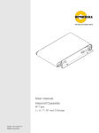
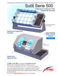
Read this unsers manual thoroughly before beginning assembly. Begin by situating the pedestal assembly, as shown below, within the
area you wish to place the unit.
Then follow these steps:
1. Connect the left pedestal end (1) with the right end (2) by securing them onto the lower cross bar support structure (3). The lower
cross bar support structure will be screwed down on the underside of the pedestal end parts.
8
6
4
1
3
5
7
2
Fig. 1
2. Secure the upper cross bar support structure (4) to the inside tops of each pedestal end (5). The center spreader rail (6) should
already be preinstalled.
3. Place and secure the rear support panels (8) onto the rear of the complete cross bar support structure, facing in the manner
prescribed by the fittings of the parts.
4. Assemble the left and right pedestal cover plates (7) onto the front of the completed cross bar support structure. After this is done,
the entire pedestal subassembly should be properly positioned in the permanent area where the solarium is to be operated.
9
11
10
12
Fig. 2
5
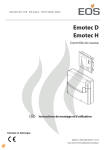
5. When permanent positioning has been completed, the canopy (9) of the solarium can be lifted onto the pedestal subassembly.
Make sure that the securing bolts (10) are within arms reach when doing this. Place the connector plates on the canopy (11) into their
hinges (12), slide the bolts into a secured and locked position, then test the movement of the canopy 10 to 12 inches to be sure that
it moves smoothly. The nuts for the securing bolts will be screwed on later when the bench is installed.
Fig. 3
13
6. If the assembly and mounting procedures as specified in steps 1 thru 5 have been done properly, the canopy should be able to be
raised and stay in the open (it can also be lowered to the closed) position. If the floor is not level, this may not be possible until such
time as the spring lift system (13) has been adjusted. When this has been accomplished, the bench assembly can be performed.
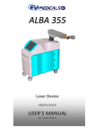
7. Reinspect the pedestal subassembly for proper installation as outlined in steps 1 thru 4. The main hot air exhaust system (14) is
located in the center of the back part of the pedestal. The air conditioner (15) is located to left of the main ventilation unit, with its
cold air output vent pointing to the left. To the right of the air conditioner are 4 sliding racks onto which the electrical components
that drive the solarium are situated. Each sliding rack has its own, unique primary control function.
From right to left youll see:
1st Rack 2nd Rack 3rd and 4th 5th Rack -
Operating switching system with contactors which run the solariums various functions.
Ballasts and capacitors for the twenty 100 Watt lamps in the bench.
Ballast and drivers for the 160 Watt lamps in the canopy.
Ballasts and capacitors for the facial tanners.
The sliding rack resisting rails (17) and main support bar (18) will be secured onto the upper and lower cross bar support structure only
after the pedestal assembly has been completely outfitted and the electrical systems connected. Install the electrical units and
component racks as shown below:
27
14
17
15
24 18
16
17
Fig. 4
8. First of all the main hot air exhaust unit (14) must be moved to the reinforcement profiles in the rear of the pedestal. Then secure it
with the enclosed hexagon socket head cap screws (M8).
Herewith it is to be noted to which side the air exhaust tube is locades. Accordingly to this the main hot air exhaust unit has to be
turned. Moreover the pulling rod has to be adapted to the assembly direction of the air exhaust unt (= side where the exhaust air
6
29
23
23
28
25
25
19
20
14
19
20
21
15
20
16
Fig. 5
goes out). That means that the pulling rod is fed to the correct hole to the rear of the exhaust unit.
Now the exhaust ducts (27) from the canopy must be connected to the upper ducts of the main hot air exhaust unit, using the 6 inch
hose and hose clamps provided. After that the exhaust air hose will be connected to the ducts (30) of the main hot air exhaust by
means of the enclosed hose clamps.
Subsequently you extend the pulling rod of the warm air feedback facility to the enclosed extension rod. At the same time this rod
is led through the holes of the guiding sheet beside the middle support. Screw the provided handle onto the end of the protruding
end of the extension bar. This controls the hot air output, which can be regulated to direct more or less hot air from the unit into the
bench during colder or warmer times of the year. Front position = flap is open, rear position = flap is cosed.
9. Place the air-conditioner and sliding electrical component racks in their proper positions as shown in illustration 4. Place all electrical
cables as shown in illustration 7 between each of the respective sliding component rack and connect each according to symbol and
color. Make sure to secure the locking screws on each of the connectors. The electrical connection of the canopy may now be made
at the rear connectors of the designated component racks in the same fashion. Finally, connect the air conditioner and the main hot
air exhaust unit, as well as the main power cable in accordance with illustration 8. The main power cable should be connected to the
primary terminal lead nrs. 5 and 4².
31
30
32
Fig. 6
7
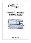
Fig. 7
Fig. 8
8
GND
2
Bu41
A2
TPI
2
1
c5
FACIAL1
(HPL1) 4
1 2 3 4 5 6 7 8 9 10
A2
A1
5
4
3
10
2
FACIAL2 AIRCON.
5
(HPL2) 3
9
A2
A1
6
TIMER
(15 min.)
c4
connection:
coinbox or
remote timer
1 2 3 4 5 6 7 8 9 10
c1
A1
c6
c2
Bu1
FAN
(Face)
St2
1
St1
6
c1
13
7
8
A2
A1
14
13
A2
A1
4
3
2
h
Air-conditioner
1 2 3
elapsed time
meter
14
Bu2
Speed
Regulator
1
c3
c2
Bu3
A2
L1 N1
TPI180
1
2
2
3
4
3
6
5
HPL2+UVA2
Bu8
2
3
c2
L2
connet to:
bench
1
UVA1
4
2
1
HPL2+UVA2
L1
6
4
c3
Bu9
5
3
Connection for für 3 x 230 V
L3 N3
lead to
drawer: bench
Bu10
Bench (20x160W)
c1
1
A1
UV
HPL1+UVA1
bench
L2 N2
exhaust air
1 2 3 4
58
57
Fans+contr
Bu5
Body Fan
1 2 3
c6
A1
c1
2
1
2
4
6
4
3
5
3
5
6
c4
7
Kl2/L3
L3
to drawers: Canopy
1
UVA2
Canopy (15x160W)
Kl2/L3
UVA1
Canopy (15x160W)
Fan
s+C
ontr
Ben
ol
ch
Kl2/L2
HID1
Kl2/L1
UVA2
HPL1
C1/1
9
4
2
8
3
1
10
6
5
1
2
2
3
4
3
4
6
5
5
6
7
connected to: Canopy
Bu6
c5
1
Kl2/L2
UVA1
Facial Tanners (6x400W)
(Center)
{
{
HID2
Facial Tanners (6x400W)
HPL2
(Left, Right outside)
HID1
C1/13
UVA2
N1
N2
N3
ON/OFF
8
9
10
4
3
C2/3
c6
HID2
Gnd
C1/15
3
2
1
8
7
Fans/Canopy
Bu7
6
5
L2-FAN
C6/3
HPL-FAN
KL2/L1
Face-Fan
L1
L2
L3
L 1+
HP
9
Fig. 9
10. Next, place the bench onto the pedestal assembly. Line the connector plate holes up by lifting the bench slightly. This can be best
done by first shoving the bench as far back onto the pedestal as possible. After lining the holes up and securing the bench onto the
pedestal by inserting the securing bolts, the bench should be lifted up and supported in place by the supporting rod (28). You may
now make the electrical connections of the bench using the receptacles on the number 3 component rack.
30
36
31
35
34
32
33
Fig. 10
Fig. 11
11. The canopy-to-bench ventilation hoses and the cold air output hose are located next to the benchs electrical cables. Connect the
forward, upper exhaust hoses of the main hot air exhaust unit (20) to the respective receptacles (23) in the bench. The cold air output
hose (21) is to be connected to its receptacle (29) in the bench (see illustration 5). Use metaal constricting band to secure these hoses
onto the receptacles.
12. Connect the cable extending from the control panel in the canopy into its receptacle located on the front component rack (illustration
9). When this has been done, and all other electrical and ventilation connections have been properly made, the front cover plate can
be affixed.
13. As shown in illustration 9, the middle cover plate (31) is connected to the pedestal subassembly from the inside. The top (30) and
bottom (32) covers are secured by spring-loaded, quick-release bolts (illustration 10) for quick service access. The locking mechanism
(35) is screwed into a bolt-washer (36), which, when the outer button (33) is depressed by use of a small screwdriver, will release the
cover plate(s).
40
41
39
37
38
Fig. 12
14. The foot and body fan can now be installed (illustration 11). The foot fan and headfan should first be connected with the corresponding
cables in the bench, and then both should be securely screwed (37-40) down onto the bench.
After this step has been completed, the solarium can be turned on to check for proper functioning.
10
Operating Instructions
The operating panel is located on the inside of the canopy, at the head end. The function switches are listed respectively below as the
appear from left to right thereon.
l Body / Head Fans - Regulates or turns off the air output to the entire body
l Facial Tanner Fans - Regulates or turns off the air output to the facial area only
l Air-conditioner - Turns A/C - cooled air on or off
l Facial Tanners Switch 1 - Regulates choice of either full or half output
l Facial Tanners Switch 2 - Turns the facial tanners on or off
l On / Off Switch - Starts and Stops the solarium.
Note: This switch is only active, when the primary timer is activated. In this case and in commercial applications,
when the unit is primed by an external timer this switch functions as an Emergency Stop.
l Facial Cooling Directional lever - Adjusts the angle of facial air flow
l Primary Timer - The primary timer is located vis-à-vis to the operating panel inside the front-end of the canopy, see Fig. 14. Select the
desired sunbathe time by means of the rotary knob. On expiration of this time, the tubes and the facial tanning
lamps are switched off automatically.
In any case, when the timer is replaced, be sure that the running time does not exceed the maximum exposure time
of 15 minutes.
Body Fan Rheostat & switch
Facial Ventilator On / Off
Airconditioner On / Off
Face Tanner Switch 1
Main On / Off Switch
Face tanner Switch 2
Facial ventilator Direction
lever
5
3
M
IN
Fig. 13
7
1
0
9
15
13
11
Fig. 14
11
Click strip
Acrylic sheet
Metal halide lamp
Filter glasses
Quick-release
Cover plate
Fig. 16
Fig. 15
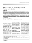
Cleaning the Solarium
A moist cloth may be used during cleaning of the metal and plastic surfaces. The acrylic sheets will collect dust on their interior surfaces,
as will the lamps themselves, as a result of electromagnetic field generation. Both the acrylic sheets and lamps should be cleaned every
200 hours of operation with a material which contains no alcohol or ammonia. To remove the bench acrylic sheet, simply flip the quickrelease click strip at the edges (illustration 16) and lift it out. The canopy acrylic sheet is removed in the same manner, but with the
person holding the sheet in the center while laying on his or her back in the solarium.
Replacement of the facial tanning lamps and filter glass in the facial tanning
cassettes:
The metal halide 400 Watt facial lamps should, like the low pressure-flourescent lamps, be maintained and replaced with regularity
according the respective manufacturers recommendations. To access a facial cassette, the cover bolt must be removed by depressing it,
which allows for the cover to swing outwards for easy removal (Fig.15). Fold the hinged filter outwards to access the lamp. Replace the
lamp by holding it ONLY ON THE FLAT END. The spring loaded lampholder allows for easy removal and replacement. DO NOT TOUCH
THE FILTER GLASS. Remove dust or dirt from the filter glass only with a material which contains no alcohol or ammonia.
Changing the filter glass is a simple matter of releasing the old glass from its carriage by removing the restricting screws. IMPORTANT:
THE SOLARIUM SHOULD AT NO TIME BE OPERATED WITH A DAMAGED OR BROKEN FILTER GLASS.
Adjusting the Spring Lifting System
The easy-to-use spring lift system of this solarium is located in the pedestal endhousings, and can be adjusted by rotating the tension
screw as shown in illustration 17. The default setting is adjusted at the factory to allow the canopy to stay in the open or closed position
upon installation. Should the tension need to be lessened or tightened by removing the lower front cover panel and rotating the
tension screws on either pedestal end with the provided Allen wrench.
Securing Screw
Endcap
Access opening to
Adjustment screw
12
Frontal cover panel
Lower front
panel cover
Quick Release
Fig. 17
Replacing the intake Filters
The fresh air intakes in the top deck and pedestal sections are covered with special filters, which should be inspected once each month
and replaced as needed. To access these filters, loosen the quick release bolts in the front of the pedestal as well as the securing screws
in the sides of the top dock and remove both. Once the side endcaps have been removed, the forward cover on the top deck can be
easily taken out, as can the front pedestal cover once the quick release bolts have been loosened. Pull the old filters out carefully from
their carriages and replace with new ones on the same manner for both pedestal and top deck.
Main Hot Air Exhaust and Additional Ventilation
In order for this machine to function properly, the hot air generated is taken out of the ambient atmosphere by way of a central exhaust
fan system and hose.
It is important that the hose not be bent more than 90 degrees and that a constant outward flow of air be maintained, insuring that no
blockage or backpressure comes into play. If the space into the which the hot air is being ventilated does not lead freely to the outside
environment, an additional fan system may be required in the building to provide an adequate flow.
It is essential that enough fresh air is available for intake for proper function, as a minimum of 1200 to 1800 cubic feet per minute of air
will be moved through the machine.
Commercial users should have louvered doors and an air-conditioning vent leading into the cabin.
This machine cannot function optimally beyond an ambient room temperature of 84 degrees Fahrenheit with more than 70 % humidity.
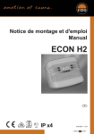
Remote Timer and / or Coinbox Connection
The Blue Dream 506 and 5012 models were designed primarily for commercial application and remote operation. Please note that the
after-cooling fan lead must be connected at all times.
The two wires between poles 2 and 4 which enables the machine to be activated by the external timer in the top deck must first be
removed before the remote timer or coinbox can be connected according to the below diagram.
When the remote timer or coinbox has run out of time and has shut down its circuit, no other function on the machine can turned on or
off via its external control panel in the top deck.
The connection of the remote timer is shown in the following diagram. Use a cord type SP-1 or SPF-1, or heavier, with a 25 foot maximum
length.
Note: In accordance with the maximum exposure limit of 15 minutes, the maximum running time of the remote timer should not exceed 15
minutes.
Rack for controlling and switching
auxiliary fan
Not connected
Fan (delayed)
Time
Mains L2
Mains L1
Gnd
Not connected
Leave this wires disconnected
and insulated !
s 1: clock operated switch
Remote timer
s1
Fig. 18
Connection of auxiliary fans
In some cases with very long exhaust hoses and if the hot air has a large height to overcome you will need a auxiliary fan to transport
the hot air outward. This fan can be connected to pole 1 (fan) and pole 3 (L2).
13
Replacement Components / Spare Parts
The longevity of the fluorescent lamps vary from manufacturer to manufacturer, but is usually between 500 and 800 hours of use.
Only authorized, original parts and factory components can be used in this machine; please make sure to have your model type and
serial number available when ordering these from your DR. KERN distributor.
Technical Data
506
Length
Breadth
Height
Division of Lamps
Canopy
Bench
Air-Conditioner
Total output
Power source
Standard
Optional
Fuse protection single phase
3 phase
14
5012
2300 mm
1350 mm
1250 mm
2300 mm
1350 mm
1250 mm
30 x 160 W VHR-Lamps
6 x 400 W Facial Tanners
20 x 100 W RUVA-Lamps
30 x 160 W VHR-Lamps
12 x 400 W Facial Tanners
20 x 100 W RUVA-Lamps
Standard
10 kW
220 V 60 Hz single phase
220 V 60 Hz 3 phase
60 A
3 x 40 A
Standard
14 kW
220 V 60 Hz single phase
220 V 60 Hz 3 phase
80 A
3 x 50 A
Warranty
With the exception of acrylic sheets and lamps, this solarium is warranted for (1) one year on all factory camponents or parts, and 30
days on labor after initial installation. Reparations that are required as a result of damage during transportation to the end-users
location, as well as any due to neglect, improper installation, or handling, are not covered.
Important note: This warranty must be activated prior to installation of the unit. To activate the warranty, please fill out the accompanying
product registration card and mail it to us. or, call (888) 765-2742 and register your solarium. Make sure to have your model and
serial number before calling.
Danger, Warning, Compliance and Identification Labels
DANGER. Ultraviolet radiation. Follow instructions. Avoid overexposure. As with natural sunlight, overexposure can cause eye and and
skin injury and allergic reations. Repeated exposure may cause premature aging of the skin and skin cancer. Wear PROTECTIVE
EYEWEAR, FAILURE TO MAY RESULT IN SEVERE BURNS OR LONG-TERM INJURY TO THE EYES.
Medications or cosmetics may increase your sensitivity to the ultraviolet radiation. Consult physician before using sunlamp if you are
using medications or have a history of skin problems or believe yourself especially sensitive to sunlight. If you do not tan in the sun,
your are unlikely to tan from the use of this product. Minimum use distance is 1 inch or 2.54 centimeter. Tanning may appear after one
application provided that your skin is capable of developing a suntan. Allow 48 hours between sessions to obtain a base tan, once or
twice per week to maintain appearance.
WARNING. Read the instructions booklet before using this product.
When using a folding combination machine with bench and canopy, lie down on the bench and pull the canopy down until it will move
no further. When using a canopy only, lie down and pull the canopy down as for as the stand will allow.
Operation of this device closer to the body than the recommended minimum distance for use may result in overexposure.
Recommended eyewear: Provided eyeshields (Intexco Nr. 5635/1s) or equivalent eyewear as defined under 21 CFR 1040.20, 2(b) (6).
One pair of protective eyewear is furnished with this equipment and should be worn by all persons in the room when lamps are on.
Disconnect power cord before attempting to clean, replace lamps, or engage in the maintanace of this product. THE FOLLOWING
LAMPS HAVE BEEN CERTIFIED FOR USE IN THIS EQUIPMENT: Cosmolux RCS, Cosmolux CS, Cosmolux UVA plus, Cosmolux VHR, Philips
HPA 400/30s or compatible types. THIS PRODUCT CONFORMS WITH PERFORMANCE STANDARDS FOR SUN LAMP PRODUCTS UNDER
21 CFR PART 1040.20.
$
Guarantee / Registration card
Ireespective of the dealers obligations under his sale agreement, the guarantee period for sunbeds (radiation sources excepted) is one
year from date of purchase. In the case of commercial use e.g. in hotels or guest-houses, the guarantee period is six month from
purchase.
Within these time limits, we shall rectify, free of charge, damage demonstrably attributabel to defects of material or workmanship.
Damage caused by misoperation or improper use does not come under the guarantee. Any transport costs incurred in the dispatch or
return of equipment cannot accepted by us.
In the event of complaint, please send this guarantee slip - together with the sale invoice in all cases - to the dealer, after-sales service
centre, or direct to the manufacturer.
Date of purchase:
Dealer:
15
Service Address
DR. KERN GMBH
D-35759 Driedorf
Phone: 49 27 75 / 8 22 21 or 8 22 76
Fax: 49 27 75 / 8 24 55
e-Mail: [email protected]
Internet: http://www.dr-kern.de