1
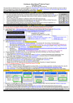
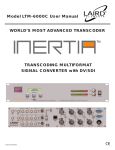
Kramer Electronics, Ltd.
USER MANUAL
Model:
811
Video / Audio Generator
Contents
Contents
1
2
3
4
5
5.1
Introduction
Getting Started
Overview
Your 811 Video / Audio Generator
Installing on a Rack
Before Installing on a Rack
CAUTION!!
5.1.1
5.2
6
6.1
7
7.1
7.2
8
9
Instructions for Rack-Mounting
Connecting the 811 Video / Audio Generator
Connecting the Balanced/Unbalanced Stereo Audio Output
Operating the 811 Video / Audio Generator
Adjusting your Video Equipment
Adjusting your Audio Equipment
Defining the 811 Test Patterns
Technical Specifications
1
1
1
2
5
5
5
5
6
7
8
8
8
9
14
Figures
Figure 1: 811 Video / Audio Generator – Front and Rear View
Figure 2: 811 Video / Audio Generator Underside
Figure 3: Connecting the 811 Video / Audio Generator
Figure 4: Connecting the Balanced Stereo Audio Output
Figure 5: Connecting an Unbalanced Output
2
4
6
7
7
Tables
Table 1: Front Panel 811 Video / Audio Generator Features
Table 2: Rear Panel 811 Video / Audio Generator Features
Table 3: Front Panel 811 Video / Audio Generator Underside Features
Table 4: Recommended Ambient Temperature and Humidity Range
Table 5: Test Pattern Definitions
Table 6: Technical Specifications of the 811 Video / Audio Generator
3
3
4
5
9
14
i
Introduction
1
Introduction
Welcome to Kramer Electronics (since 1981): a world of unique, creative and
affordable solutions to the infinite range of problems that confront the video,
audio and presentation professional on a daily basis. In recent years, we have
redesigned and upgraded most of our line, making the best even better! Our
350-plus different models now appear in 8 Groups1, which are clearly defined
by function.
Congratulations on purchasing your Kramer 811 Video / Audio Generator,
which is ideal for testing video and audio equipment.
The package includes the following items:
811 Video / Audio Generator
Power cord
This user manual2
2
Getting Started
We recommend that you:
Unpack the equipment carefully and save the original box and packaging
materials for possible future shipment
Review the contents of this user manual
Use Kramer high performance high resolution cables3
3
Overview
The desktop-sized 811 Video / Audio Generator is designed for the testing
and adjusting of video and audio equipment. It outputs a composite video
signal, an s-Video signal, a component video signal, 2 SDI signals, 6 black
burst signals4 and a balanced audio signal.
1 GROUP 1: Distribution Amplifiers; GROUP 2: Video and Audio Switchers, Matrix Switchers and Controllers; GROUP 3:
Video, Audio, VGA/XGA Processors; GROUP 4: Interfaces and Sync Processors; GROUP 5: Twisted Pair Interfaces;
GROUP 6: Accessories and Rack Adapters; GROUP 7: Scan Converters and Scalers; and GROUP 8: Cables and Connectors
2 Download up-to-date Kramer user manuals from the Internet at this URL: http://www.kramerelectronics.com
3 The complete list of Kramer cables is on our Web site at http://www.kramerelectronics.com
4 To simultaneously genlock several video sources in a studio
1
Your 811 Video / Audio Generator
In addition, the 811 Video / Audio Generator:
Lets you adjust the amplitude and frequency of the balanced audio signal
Lets you determine the video output standard PAL or NTSC via the
VIDEO STANDARD button
Offers 74 static or moving patterns, all of which are available in each
video standard
Transmits a video signal to each output simultaneously
The 811 can be rack-mounted using the RK-80 19” rack adapter. To achieve
the best performance:
Connect only good quality connection cables, thus avoiding interference,
deterioration in signal quality due to poor matching, and elevated noiselevels (often associated with low quality cables)
Avoid interference from neighboring electrical appliances and position
your Kramer 811 away from moisture, excessive sunlight and dust
4
Your 811 Video / Audio Generator
Figure 1, Table 1 and Table 2 define the 811:
Figure 1: 811 Video / Audio Generator – Front and Rear View
2
KRAMER: SIMPLE CREATIVE TECHNOLOGY
Your 811 Video / Audio Generator
Table 1: Front Panel 811 Video / Audio Generator Features
12
13
Function
Illuminated switch for turning the unit ON or OFF
Press to decrease the signal amplitude
Press to increase the signal amplitude
Displays the audio signal amplitude (from 19dBu to
+10dBu)
- Button
Press to decrease the audio frequency
+ Button
Press to increase the audio frequency
FREQUENCY 7-segment Display Displays the audio frequency (from 0.02kHz to 20kHz)
- Button
Press to select the previous pattern number
+ Button
Press to select the next pattern number
1
PATTERN 7-segment Display
Displays the video pattern number (from 0 to 73), see section 8
STANDARD Button
Toggles between selecting the NTSC and the PAL video
standards
NTSC LED
Illuminates when the NTSC video standard is selected
PAL LED
Illuminates when the PAL video standard is selected
AUDIO
5
6
7
8
9
10
11
Feature
POWER Switch
- Button
+ Button
AMPLITUDE 7-segment Display
VIDEO
#
1
2
3
4
Table 2: Rear Panel 811 Video / Audio Generator Features
#
14
15
16
17
18
19
20
21
22
Feature
Function
BLACK BURST OUT BNC Connectors Connect the black burst outputs (from 1 to 6) to the video
acceptors
V BNC Connector
Connect to the component2 video acceptor
U BNC Connector
Y BNC Connector
CV BNC Connector
SDI BNC Connector
AUDIO OUT 5-PIN
Terminal Block Connector
YC OUT 4p Connector
PK Dipswitches3
1 2 3 4
ON
23
Connect to the composite video acceptor
Connect to the SDI acceptor
Connect to the balanced (or unbalanced) audio acceptor
Connect to the s-Video acceptor
DIP 3 (P): ON for pedestal (7.5 IRE offset selection for
NTSC); OFF for no pedestal
DIP 4 (K): OFF for activating the Kramer logo; ON for
deactivating it
P K
Power Connector with Fuse
AC connector enabling power supply to the unit
Figure 2 and Table 3 define the 811 underside BB trimmers (lower right
side):
1 Several pattern numbers (specified in Table 5) freeze the moving pattern on the screen
2 For component video, connect all three connectors: Y, U, and V (also known as: Y, B-Y, and R-Y, and sometimes called Y,
Cb, and Cr)
3 DIPs 1 and 2 are not used. By default, all DIPs are set to OFF
3
Your 811 Video / Audio Generator
Figure 2: 811 Video / Audio Generator Underside
Table 3: Front Panel 811 Video / Audio Generator Underside Features
#
1
2
Feature
BB OFFSET Trimmer
BB GAIN Trimmer
Function
Adjusts1 the black burst offset level
Adjusts1 the black burst gain
1 Insert a screwdriver into the small hole and carefully rotate it to adjust the level
4
KRAMER: SIMPLE CREATIVE TECHNOLOGY
Installing on a Rack
5
Installing on a Rack
This section describes what to do before installing on a rack (see section 5.1)
and how to install on a rack (see section 5.2).
5.1 Before Installing on a Rack
Before installing the machine in a 19" rack, be sure that the environment is
within the recommended range:
Table 4: Recommended Ambient Temperature and Humidity Range
Operating temperature range
Operating humidity range
Storage temperature range
Storage humidity range
5.1.1
+5 to +45 Deg. Centigrade
5 to 65 % RHL, non-condensing
-20 to +70 Deg. Centigrade
5 to 95% RHL, non-condensing
CAUTION!!
When installing the 811 in a 19" rack, avoid hazards by taking care that:
1.
It is located within the recommended environmental conditions, as the
operating ambient temperature of a closed or multi-unit rack assembly
may exceed the room ambient temperature.
2.
Once rack-mounted, enough air will still flow around the machine.
3.
The machine is placed straight in the correct horizontal position.
4.
You do not overload the circuit(s). When connecting the machine to the
supply circuit, overloading the circuits might have a detrimental effect on
overcurrent protection and supply wiring. Refer to the appropriate
nameplate ratings for information. For example, for fuse replacement, see
the value printed on the product label.
5.
The machine is earthed (grounded) in a reliable way and is connected only
to an electricity socket with grounding. Pay particular attention to supply
connections other than direct connections to the branch circuit (for
example, the use of power strips), and that you use only the power cord
that is supplied with the machine.
5.2 Instructions for Rack-Mounting
To install the 811 in a 19" rack, place the rack ears of the rack adapter1
against the rack rails of the rack, and insert the proper rack screws through
each of the four holes in the rack ears.
1 Always mount the machine in the rack before you attach any cables or connect the machine to the power. If you are using a
Kramer rack adapter kit (for a machine that is not 19"), refer to the Rack Adapters user manual (download it at:
http://www.kramerelectronics.com) for installation instructions
5
Connecting the 811 Video / Audio Generator
6
Connecting the 811 Video / Audio Generator
To use your 811 Video / Audio Generator, connect one or more of the
outputs1, as the example in Figure 3 illustrates:
1.
Connect the BLACK BURST OUT 1 BNC connector to a black burst
acceptor (for example, a genlockable camera).
2.
Connect the CV BNC connector to the composite video acceptor (for
example, a display).
3.
Connect the COMP. (component video) Y, U and V BNC connectors to
the component video acceptor (for example, a Betacam recorder).
4.
Connect the SDI 1 BNC connector to the SDI acceptor (for example, an
SDI display).
5.
Connect the s-Video (Y/C) 4p YC OUT connector to the s-Video (Y/C)
acceptor (for example, an AV Switcher (Diagnostic)).
6.
Connect the AUDIO OUT terminal block to the audio acceptor (for
example, an AV Switcher (Diagnostic)), see section 6.1.
7.
Connect the power cord (not illustrated in Figure 3).
Genlockable
Camera
AV
Switcher
(Diagnostic)
Betacam
Recorder
Display
SDI Display
Figure 3: Connecting the 811 Video / Audio Generator
1 You do not have to connect all the outputs
6
KRAMER: SIMPLE CREATIVE TECHNOLOGY
Connecting the 811 Video / Audio Generator
6.1 Connecting the Balanced/Unbalanced Stereo Audio Output
This section illustrates how to wire:
A balanced output connection, see Figure 4
An unbalanced audio output, see Figure 5
Figure 4: Connecting the Balanced Stereo Audio Output
Figure 5: Connecting an Unbalanced Output
7
Operating the 811 Video / Audio Generator
7
Operating the 811 Video / Audio Generator
This section describes how to adjust your video and audio equipment.
7.1 Adjusting your Video Equipment
To adjust your video equipment using the 811, do the following:
1.
Press the VIDEO PATTERN + or - buttons1 to generate the required
pattern.
The VIDEO PATTERN 7-segment display shows the selected pattern
number.
2.
Observe the output on the acceptors (see Table 5 for reference).
3.
Adjust the video equipment, as required.
You can only select one video pattern at a time for all the connected outputs
7.2 Adjusting your Audio Equipment
To adjust your audio equipment using the 811, do the following:
1.
Press the AUDIO AMPLITUDE + or – buttons, and/or the AUDIO
FREQUENCY + or – buttons to set the desired audio amplitude and
frequency.
2.
Adjust your audio equipment, as required.
1 To display the next pattern or the previous pattern, respectively
8
KRAMER: SIMPLE CREATIVE TECHNOLOGY
Defining the 811 Test Patterns
8
Defining the 811 Test Patterns
Table 5 describes the 811 test Patterns:
Table 5: Test Pattern Definitions
0
Pattern #
Name
Black burst
Display
Can be used to:
Synchronize machines
Check for noise in the picture
1-3
Color Bars
Check the capability of the device to
create fully saturated primary and
secondary colors and check video
and TV monitors
4-5
SMPTE Bars
Align the NTSC color transmission
system
Adjust color and hue through a blue
filter
Adjust brightness and contrast
6-8
Gray Scale bar
and Chart
Check the contrast, the brightness
and the linearity of the video
amplifiers and D/A converters
Check the precision of the colorcoding and beam focusing (color
shifts from gray)
Fine-tune the color balance
Control contrast
9-14
Full field color
raster patterns
at 75%
amplitude
Check color purity and display
chrominance uniformity
Check for missing pixels on a TFT or
LCD Monitor (switch to Red, Green
and Blue, and observe the screen
for missing pixels, which look dark or
stuck)
Check power supply stability, and
video processing circuits noise
9
Defining the 811 Test Patterns
Pattern #
15-21
Name
Gray shades in
a box
22
White screen
Set the white color
Evaluate white field uniformity
Measure the display light output
23-25
SDI, PLL and
equalizer test
Test for the equalizer and PLL in
SDI systems
26-27
Center cross
Indicate the screen safe zone for
text, subtitles, logo and title
placement (5% and 10%)
Center align screen for text and
pictures
28, 29, 33,
34, 35
Crosshatch
Adjust the linearity and convergence
Perform an overall check of the
display’s capability of producing fully
saturated primary and secondary
colors
Estimate the quality of the projector
lens (for the fine crosshatch pattern)
Check the quality of video scalers
and de-interlacers
30, 31, 32
Colored
Crosshatch
Evaluate the quality and adjustment
of each color channel, especially
useful for guns and masks for CRT
10
Display
Can be used to:
Check the contrast and power
stability of the video amplifiers and
geometry artifacts at different
brightness steps on the screen
Adjust the contrast
KRAMER: SIMPLE CREATIVE TECHNOLOGY
Defining the 811 Test Patterns
Pattern #
36-37
Name
1
PLUGE
Display
Can be used to:
Check the black level (brightness
control)
Estimate the response time of the
color amplifiers in the CRT monitor
38
Continuous
Grayscale
Image
Check the quality of the video
amplifier, D/A converter and video
processing circuits, as well as the
linearity, dynamic range, noise and
number of bits for D/A
39-43
Gray and
colored vertical
bands
Multiburst
Check the frequency response for Y,
U and V separated, and YUV
combined
44-45
Fine squares
and dots
Check static convergence and focus
Check shadowing
46, 47
Focus
Test the focus in the corners and the
center of the screen
48
Checker-board
Check the regulation of the CRT
video drive power supply circuits
Check horizontal and vertical
deflection and linearity
1 PLUGE is Picture Line-Up Generation Equipment. The PLUGE pattern checks the black level on the video screen
11
Defining the 811 Test Patterns
Pattern #
49-50
Name
Black and white
vertical and
horizontal
51
Black and white
pixels
Perform high frequency testing for
luminance
52
Modulated steps
Check chrominance response with
respect to luminance level
53
Pulse and bar
Check hue response
Check chroma-luma delay
54
Bowtie
Check timing and gain error
55
Hum bar pattern
Locate and evaluate low level
ground loop type signal interference
12
Display
Can be used to:
Check the regulation of the CRT
video drive power supply circuits
Check horizontal and vertical
deflection and linearity
KRAMER: SIMPLE CREATIVE TECHNOLOGY
Defining the 811 Test Patterns
Pattern #
56
Name
Black and white
Flashing
57, 58
Changing Gray
levels (black to
white)
Display
Can be used to:
Check the screen and power-supply
response time
Check the minimum to maximum Y
level
Note: Press pattern 58 to freeze the test
pattern on the screen
59, 60
Changing colors
in motion
Check the changing of colors on
screen
Note: Press pattern 60 to freeze the
moving test pattern on the screen
61,63,65
Moving
horizontal,
vertical and
diagonal lines
Evaluate the time of pixel switching
for LCD monitors (the length and
brightness of the “white tail” following
the moving line)
The diagonal pattern tests the anti
aliasing performance of scalers and
video devices
Note: Press patterns 62, 64 and 66 to
freeze the moving test pattern on the
screen
67, 69
Aperture moving
over color bar
background and
bouncing circle
with or without
the Kramer logo
Evaluate the time needed for pixel
switching for LCD monitors (the
brightness and length of the “tail” for
different colors
Function as screen saver
Note: Press patterns 68, 70 to freeze the
moving test pattern on the screen
71
Circles (aspect
ratio)
Adjust the aspect ratio of your
monitor
Adjust the safe zones (5% and 10%)
and the center of the image
13
Technical Specifications
Pattern #
72-73
9
Name
Test patterns
Display
Can be used to:
Evaluate a large number of
parameters on one screen (color,
brightness, contrast, geometry and
so on).
The Kramer logo can be
activated/deactivated via the rear panel
dipswitches, see Table 2
Technical Specifications
1
Table 6: Technical Specifications of the 811 Video / Audio Generator
VIDEO OUTPUTS:
AUDIO OUTPUTS:
MAX. OUTPUT LEVEL:
DIFF. GAIN (PAL/NTSC):
DIFF. PHASE (PAL/NTSC):
K-FACTOR (PAL/NTSC):
S/N RATIO (PAL/NTSC):
SDI Jitter:
CONTROLS:
COUPLING:
AUDIO THD + NOISE:
AUDIO 2nd HARMONIC:
POWER SOURCE:
DIMENSIONS:
WEIGHT:
ACCESSORIES:
OPTIONS:
6 x Black Burst: 1Vpp/75 on BNC connectors;
1 x CV: 1Vpp/75 on a BNC connector;
1 x YC: 1Vpp/75 (Y); 0.3Vpp/75 (C) on a 4p connector;
1 x Component: (R, R-Y, B-Y): 1V, 0.7V, 0.7 Vpp/75 on BNC connectors;
2 x SDI: SMPTE-259M, ITU-R BT.601 serial video, 75 on a BNC
connector
1 balanced audio on a detachable terminal block
VIDEO: 1Vpp for CV, YC and YUV;
AUDIO: 3.5V
SDI: 800mV
CV: 1.2/1.2%; YC: 0.2/0.1%
CV: 0.6/0.3Deg.; YC: 0.4/0.1Deg.
CV: 0.5/0.5%; YC: 0.5/0.4%; YUV: 0.5/0.4%
VIDEO: CV: 81/80dB; YC: 80/80dB;
AUDIO: 66dB (19kHz)
YUV: 77/78dB
< 0.2VI
Black level2: -0.28V to +0.44V;
AUDIO: AC
Black Gain: -1.9dB to +1.6dB
Freq. Range: 20Hz to 20kHz;
Level: 128mV to 3.5V
VIDEO: DC
0.06% (8kHz)
0.13% (8kHz)
13.8VA
22cm x 18cm x 4.5cm (8.7” x 7” x 1.7”, W, D, H)
1.3 kg. (2.9 lbs.) approx.
Power cord
Rack adapter RK-80
1 Specifications are subject to change without notice
2 Active only at black burst outputs
14
KRAMER: SIMPLE CREATIVE TECHNOLOGY
LIMITED WARRANTY
Kramer Electronics (hereafter Kramer) warrants this product free from defects in material and workmanship under the
following terms.
HOW LONG IS THE WARRANTY
Labor and parts are warranted for seven years from the date of the first customer purchase.
WHO IS PROTECTED?
Only the first purchase customer may enforce this warranty.
WHAT IS COVERED AND WHAT IS NOT COVERED
Except as below, this warranty covers all defects in material or workmanship in this product. The following are not covered
by the warranty:
1.
2.
3.
Any product which is not distributed by Kramer, or which is not purchased from an authorized Kramer dealer. If you are
uncertain as to whether a dealer is authorized, please contact Kramer at one of the agents listed in the web site
www.kramerelectronics.com.
Any product, on which the serial number has been defaced, modified or removed.
Damage, deterioration or malfunction resulting from:
i)
Accident, misuse, abuse, neglect, fire, water, lightning or other acts of nature
ii)
Product modification, or failure to follow instructions supplied with the product
iii)
Repair or attempted repair by anyone not authorized by Kramer
iv)
Any shipment of the product (claims must be presented to the carrier)
v)
Removal or installation of the product
vi)
Any other cause, which does not relate to a product defect
vii)
Cartons, equipment enclosures, cables or accessories used in conjunction with the product
WHAT WE WILL PAY FOR AND WHAT WE WILL NOT PAY FOR
We will pay labor and material expenses for covered items. We will not pay for the following:
1.
2.
3.
Removal or installations charges.
Costs of initial technical adjustments (set-up), including adjustment of user controls or programming. These costs are the
responsibility of the Kramer dealer from whom the product was purchased.
Shipping charges.
HOW YOU CAN GET WARRANTY SERVICE
1.
2.
3.
To obtain service on you product, you must take or ship it prepaid to any authorized Kramer service center.
Whenever warranty service is required, the original dated invoice (or a copy) must be presented as proof of warranty coverage,
and should be included in any shipment of the product. Please also include in any mailing a contact name, company, address, and
a description of the problem(s).
For the name of the nearest Kramer authorized service center, consult your authorized dealer.
LIMITATION OF IMPLIED WARRANTIES
All implied warranties, including warranties of merchantability and fitness for a particular purpose, are limited in duration to
the length of this warranty.
EXCLUSION OF DAMAGES
The liability of Kramer for any effective products is limited to the repair or replacement of the product at our option. Kramer
shall not be liable for:
1.
2.
Damage to other property caused by defects in this product, damages based upon inconvenience, loss of use of the product, loss
of time, commercial loss; or:
Any other damages, whether incidental, consequential or otherwise. Some countries may not allow limitations on how long an
implied warranty lasts and/or do not allow the exclusion or limitation of incidental or consequential damages, so the above
limitations and exclusions may not apply to you.
This warranty gives you specific legal rights, and you may also have other rights, which vary from place to place.
NOTE: All products returned to Kramer for service must have prior approval. This may be obtained from your dealer.
This equipment has been tested to determine compliance with the requirements of:
EN-50081:
"Electromagnetic compatibility (EMC);
generic emission standard.
Part 1: Residential, commercial and light industry"
EN-50082:
"Electromagnetic compatibility (EMC) generic immunity standard.
Part 1: Residential, commercial and light industry environment".
CFR-47:
FCC Rules and Regulations:
Part 15: “Radio frequency devices
Subpart B – Unintentional radiators”
CAUTION!
Servicing the machines can only be done by an authorized Kramer technician. Any user who makes changes or modifications to
the unit without the expressed approval of the manufacturer will void user authority to operate the equipment.
Use the supplied DC power supply to feed power to the machine.
Please use recommended interconnection cables to connect the machine to other components.
15
For the latest information on our products and a list of Kramer
distributors, visit our Web site: www.kramerelectronics.com,
where updates to this user manual may be found.
We welcome your questions, comments and feedback.
Safety Warning:
Disconnect the unit from the power supply before
opening/servicing.
Caution
Kramer Electronics, Ltd.
Web site: www.kramerelectronics.com
E-mail: [email protected]
P/N: 2900-000060 REV 1