1
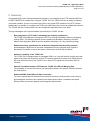
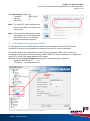
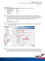
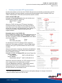
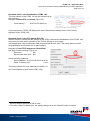
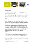
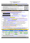
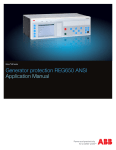
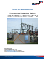
TICRO 100 - Application Note Synchronize Protection Relays (ABB RET670) to IEEE 1588/PTPv2 By Wolfgang Schenk © 2014 by OMICRON Lab – V1.00 Visit www.omicron-lab.com for more information. Contact [email protected] for technical support. Smart Timing Solutions TICRO 100 - Application Note Synchronize Protection Relays (ABB RET670) to IEEE 1588/PTPv2 Page 2 of 19 Table of Contents 1 EXECUTIVE SUMMARY ....................................................................................................................................... 3 2 TECHNICAL BACKGROUND .............................................................................................................................. 3 2.1 THE IRIG-B TIME CODE .......................................................................................................................................... 3 2.2 PRECISION TIME PROTOCOL (PTP) IEEE 1588-2008............................................................................................ 3 2.3 W HY TO USE THE OPTICAL INPUT OF THE RET670.................................................................................................. 4 APPLICATION SETUP ......................................................................................................................................... 5 3 3.1 BLOCK DIAGRAM ..................................................................................................................................................... 5 3.2 CONNECTING THE RET670 TO THE TICRO 100..................................................................................................... 6 3.3 PTP SETTINGS OF THE TICRO 100 ....................................................................................................................... 6 3.4 IRIG-B SETTINGS OF THE TICRO 100 ................................................................................................................... 8 3.4.1 Setup of Output 4 (Fiber) ............................................................................................................................. 8 3.4.2 Setup of Output 5 (Fiber) ............................................................................................................................. 8 3.4.3 Output overview ............................................................................................................................................ 9 3.5 IRIG-B SETTINGS AT THE RET670 FROM THE FRONT PANEL .................................................................................. 9 4 CHECKING SUCCESSFUL SYNCHRONIZATION .......................................................................................... 11 5 SUMMARY ........................................................................................................................................................... 12 REFERENCES ............................................................................................................................................................. 13 APPENDIX .................................................................................................................................................................... 14 A. a. b. c. PTP SETTINGS OF THE TIME SYNCHRONIZATION SYSTEM .................................................................................... 14 PTP Settings of OTMC 100p ...................................................................................................................... 14 PTP Settings of the Hirschmann RSP20.................................................................................................... 15 Checking of successful PTP synchronization ............................................................................................ 17 Note: Detailed settings of the TICRO 100 are explained in the TICRO 100 user manual. Download the TICRO 100 user manual at: http://www.omicron-lab.com/ticro-100/downloads.html Note: All SW settings are done with TICRO firmware version ticro100-1.01.0013 or higher. Download the latest firmware at: http://www.omicron-lab.com/ticro-100/downloads.html#2 Note: The Grandmaster clock and the infrastructure have to be IEEE 1588/PTPv2 capable. We used the OTMC 100 as PTP Grandmaster clock. Download additional information at: http://www.omicron-lab.com/otmc-100/product-description.html Smart Solutions SmartMeasurement Timing Solutions TICRO 100 - Application Note Synchronize Protection Relays (ABB RET670) to IEEE 1588/PTPv2 Page 3 of 19 1 Executive Summary This Application Note shows how to integrate non PTP compliant IEDs into IEEE 1588/PTPv2 time synchronization infrastructures. In detail it shows, how to synchronize ABB Protection Relays1 with optical synchronization inputs using the TICRO 100 PTP Time Converter. The following topics are covered: - Basic settings at the TICRO 100 and the RET670 Verification if the relay has been successfully synchronized Selection of the correct PTP network settings 2 Technical Background The North American Blackout back in August 2003 visualized how painful and time consuming it can be to align data, whose time stamps are derived from inaccurate time references. As a result the task force investigating the blackout demanded a regulation that ensures a minimum absolute accuracy for time stamped disturbance event data. With the adoption of the NERC2 Standard PRC-018-1 in 2006 it is now a legal obligation that all recorded data has to have an accuracy of 2 ms or better in relation to UTC3. (see [1], page 1) Especially with the integration of Smart Grids, the standard IEC 61850 becomes important. In the IEC 61850-9-5 standard, the time accuracy requirements for time tagging of events and time synchronized measurements are summarized in five time performance classes T1 to T5 which range from 1 ms to 1 μs. (see [1], page 2) 2.1 The IRIG-B Time code The IRIG Time Codes were developed in 1960 by a working group of the US Military to allow standardized time distribution and synchronization of technical equipment. The IRIG-B Code transmits the time information in a 100 bit telegram every second. A synchronization accuracy between 1 ms to 10 μs can be achieved. For optical links unmodulated IRIG-B signals4 are used. 2.2 Precision Time Protocol (PTP) IEEE 1588-2008 The Precision Time Protocol (PTP) was developed in 2002 to achieve a higher synchronization accuracy over Ethernet than the one so far provided by NTP. With NTP synchronization accuracies in the range from 10 ms to 1 ms can achieved. This is not sufficient for the synchronization of all technical equipment in a substation. Therefore protection equipment is currently controlled and monitored via Ethernet, but synchronized via a parallel system like IRIG-B. 1 In particular an ABB RET670 is used. NERC: North American Electric Reliability Cooperation 3 UTC: Universal Coordinated Time Scale 4 IRIG-B: Inter Range Instrumentation Group Format B ([2], page 4-1, Figure 4-1) 2 Smart Solutions SmartMeasurement Timing Solutions TICRO 100 - Application Note Synchronize Protection Relays (ABB RET670) to IEEE 1588/PTPv2 Page 4 of 19 PTP distributes the time synchronization information also via Ethernet, the achievable accuracy is in the 100 ns range. Contrary to IRIG-B no additional wiring is required. PTP uses Ethernet and therefore has the advantage, that all redundancy features of Ethernet networks can be used. Using two grandmaster clocks is an easy and effective method to increase the availability of the time synchronization to all clients. Additionally the best master clock algorithm (BMCA) offered by PTP ensures that always the best available master clock in the network is used to synchronize the connected equipment. More details can be found in [1], page 5-6. 2.3 Why to use the optical input of the RET670 There are different reasons to use the optical input of the IRIG-B time synchronization module of the RET670. All of this reasons are independent of the use of the TICRO 100, since the TICRO 100 supports electrical, opto coupler and optical outputs (see [3], page 4). The main reasons to use the optical interface are its reliability and immunity against EMI5. The optical link can cover a cable length from a few meters up to 2 km, using 62.5/125 µm multimode fiber, without any restriction regarding the signal quality. In comparison an electrical IRIG-B link is limited to 100 m using unmodulated signals or 300 m using modulated signals. In a substation setup the optical fiber can cover any ordinary distance with a single link. The optical fiber offers a perfect insulation between the transmitter and receiver of the time synchronization network. There is only one restriction which should kept in mind: The average signal delay across an optical or electrical link is about 5 ns/m. 5 EMI: Electro Magnetic Interference Smart Solutions SmartMeasurement Timing Solutions TICRO 100 - Application Note Synchronize Protection Relays (ABB RET670) to IEEE 1588/PTPv2 Page 5 of 19 3 Application Setup The following chapter covers a typical time synchronization setup with the TICRO 100 and the RET670 using the RET670’s optical time sync input. It shows how to connect the relay to the TICRO 100, the necessary steps to configure the TICRO 100 and the RET670. 3.1 Block diagram The used setup consists of an OMICRON Lab OTMC 100 PTP Masterclock, a PTP compliant Ethernet switch, a PC, the TICRO 100 PTP time converter and the RET670 protection relay. The PTP Masterclock receives its reference time from GPS and maintains an accuracy of ±100 ns in comparison to UTC while locked to GPS. All connected PTP compliant equipment like the PTP switch and the TICRO 100 are synchronized via Ethernet. The achieved accuracy for a simple setup like this is in the range of better than ±200 ns. The TICRO 100 generates the IRIG-B signal to synchronize the RET670 and a 1PPS-Signal to synchronize a merging unit. Figure 1: Block Diagram of PTP setup The PoE Injector, the PTP Switch, the TICRO 100 and the RET670 are isolated from each other, since the data connection is done by optical fiber. The PoE-Injector supplies the OTMC 100 PTP Masterclock (outside the building) with electrical power via an electrical RJ45 Ethernet connection. The distance between PoE-Injector and OTMC 100 can be up to 100 m the distance between PoEInjector and PTP-Switch is optical and could be up to 2 km without any restrictions. Smart Solutions SmartMeasurement Timing Solutions TICRO 100 - Application Note Synchronize Protection Relays (ABB RET670) to IEEE 1588/PTPv2 Page 6 of 19 3.2 Connecting the RET670 to the TICRO 100 The optical time synchronization input of the RET670 is located at the rear side of the IED as shown in Figure 3. For this application the first optical output of the TICRO 100 was connected with a 62.5/125 μm multimode fiber (with red marking) to the RET670. The second optical output was used to provide a 1pps signal to synchronize a merging unit. (See Figure 2) Figure 3: Time Synchronization Input of RET670 Figure 2: Connecting RET670 with TICRO 100 3.3 PTP Settings of the TICRO 100 To ensure proper operation all PTP components in the network including the TICRO 100 need to be configured to the same PTP-Mode. In this section all PTP settings for the TICRO 100 are shown. Setup information for the remaining PTP components like the PTP switch and the PTP master clock can be found in Appendix A. The PTP master clock defines the settings for all other components inside the PTP system. A typical PTP-Mode for applications in substations is the PTP profile for power systems described in IEEE C37.238-20116. The TICRO 100 can be easily set-up via its web interface as shown on the next page.7 6 IEEE Standard Profile for use of IEEE 1588 Precision Time Protocol in Power System Applications For the PTP settings applied to the TICRO 100 default settings where chosen, this values might be different for other PTP networks. 7 Smart Solutions SmartMeasurement Timing Solutions TICRO 100 - Application Note Synchronize Protection Relays (ABB RET670) to IEEE 1588/PTPv2 Page 7 of 19 Navigate to Configuration/PTP and apply the following settings in the respective Tabs: Tab General (Figure 4): - PTP profile: Power systems - Max. GM inaccuracy: Up to 1 µs (optional) Figure 4: General PTP settings of the TICRO 100 Remark: The max. GM inaccuracy can be set, to ensure the TICRO 100 switches to its internal oscillator in case that the Grand master clock inaccuracy exceeds the set limit. Tab Default (Figure 5): - domain number: 0 Figure 5: Default PTP settings of the TICRO 100 Tab Port (Figure 6): - Transport: IEEE 802.3 - VLAN Id: 0 - VLAN PCP: 4 Figure 6: Port PTP settings of the TICRO 100 Note: All not mentioned parameters in the figures above are not changed from their default values. The setting of these parameter are optional. Smart Solutions SmartMeasurement Timing Solutions TICRO 100 - Application Note Synchronize Protection Relays (ABB RET670) to IEEE 1588/PTPv2 Page 8 of 19 3.4 IRIG-B Settings of the TICRO 100 This section shows how to configure the optical outputs of the TICRO 100 to provide the signals required by the connected equipment. 3.4.1 Setup of Output 4 (Fiber) The Output 4 (Fiber) connected to the RET670 needs to be configured as IRIG-B output. Navigate to Configure/Output and apply the following settings in the respective Tabs: Θ 4 (Fiber) (Figure 7): - Time base: UTC - Mode: IRIG-B - Code expressions: Control functions Off Straight binary seconds Off BCDYEAR On These settings represent IRIG-B 006. Figure 7: Sets the Fiber Output 4 of the TICRO 100 to IRIG-B Note: Select the check boxes for straight binary seconds and/or control functions to select different IRIG-B00x codes. 3.4.2 Setup of Output 5 (Fiber) The merging unit connected to Output 5 (Fiber) requires a 1PPS pulse. In the following example a pulse width of 10 ms is used. Navigate to Configure/Output and apply the following settings in the respective Tabs: Θ 5 (Fiber) (Figure 8): - Time base: - Mode: - Pulses per second: - Pulse width: - Time reference: UTC PPX 1 PPS 10000000 ns Rising edge Figure 8: Sets the Fiber Output 5 of the TICRO 100 to 1PPS Remark: The IRIG-B pattern and the 1 PPS pulse are both in line with UTC. Therefore the data acquisition of the merging unit will be in line with the system time of the IED. Smart Solutions SmartMeasurement Timing Solutions TICRO 100 - Application Note Synchronize Protection Relays (ABB RET670) to IEEE 1588/PTPv2 Page 9 of 19 3.4.3 Output overview All settings can be monitored at: Status/Output/Overview (Figure 9) Figure 9: Overview of the TICRO 100 output settings On the overview page the status of all outputs is visualized. If an output is active, a green indicator is shown. In addition the Device status of the TICRO 100 is shown. When all PTP settings match, the device status will be Locked. 3.5 IRIG-B Settings at the RET670 from the front panel To set up the RET670 the HMI (Human Machine Interface) on the front panel of the IED can be used. It is also possible to use the remote software PCM600 to set the parameter for time synchronization. After startup of the RET670 navigate to the following menus and change the parameters as stated in the following tables. (Table 1, Table 2) /RET670/Settings/Time/Synchronisation/TIMESYNCHGEN: 1/General (Figure 10) Parameter Name Value Description CoarseSyncSrc OFF Coarse time synchronization source FineSyncSource IRIG-B Fine time synchronization source SyncMaster OFF Activate IED as synchronization master TimeAdjustRate Fast Adjust rate for time synchronization Table 1: settings of the parameter group TIMESYNCHGEN/General (See [4], page 81) Smart Solutions SmartMeasurement Timing Solutions Figure 10: Settings of TIMESYNCHGEN: 1 at the HMI TICRO 100 - Application Note Synchronize Protection Relays (ABB RET670) to IEEE 1588/PTPv2 Page 10 of 19 /RET670/Settings/Time/Synchronisation/SYNCHIRIG-B: 1 (Figure 11) Parameter Name SynchType Value Opto Description Type of synchronization TimeDomain LocalTime Time domain Encoding IRIG-B Type of encoding TimeZoneAs1344 PlusTZ Time zone as in 1344 standard Table 2: Settings of the parameter group SYNCHIRIG-B of the RET670 (See [4], page 83) Figure 11: Settings of SYNCHIRIG-B: 1 at the HMI To use the full functionality of the synchronization inside the IED, the following parameters can be set to process additional data information given by IRIG-B (Table 3): /RET670/Settings/Time/Synchronisation/TIMESYNCHGEN: 1/IEC61850-9-2 (Figure 12) Parameter Name HWSyncSrc Value IRIG-B AppSynch Synch SyncAccLevel Class T5 (1us) Description Hardware time synchronization source Time synchronization mode for application Wanted time synchronization accuracy Table 3: settings of the optional parameter group TIMESYNCHGEN/IEC61850-9-2 (see [4], page 81) Figure 12: Settings of IEC61850-9-2 at the HMI For details on additional IED features refer to the Technical reference manual [4] of the RET670. Smart Solutions SmartMeasurement Timing Solutions TICRO 100 - Application Note Synchronize Protection Relays (ABB RET670) to IEEE 1588/PTPv2 Page 11 of 19 4 Checking successful synchronization Once the parameters of the TICRO 100 and the RET670 are set, the time synchronization can be checked as follows at the HMI of the RET670: Navigate the HMI of the RET670 to the menu: RET670/Diagnostics/IED status/General (Figure 13) If the time synchronization via IRIG-B works correctly, you will see: - INT Warning: Off - Time Synch : Ready More Details described at the Technical Reference Manual of the RET670. (See [4], page 69, figure 24) Figure 13: RET670 synchronized to IRIG-B Time Source To test the synchronization, the optical connection between the RET670 and the TICRO 100 is disconnected. (See Figure 14) After some seconds the parameter at the display will change to (Figure 15): - INT Warning: On - Time Synch : Fail Figure 14: red IRIG-B ST Fiber disconnected Figure 15: RET670 IRIG-B Signal lost, not synchronized Figure 16: RET670 Event log When the connection between the RET670 and the TICRO 100 is re-established and the synchronization works properly again the parameters in the display change back to normal operation. (See Figure 13) The same behavior can also be monitored in the internal event log of the RET670. Navigate to RET670/Diagnostics/Internal events (see Figure 16) Here all events including the time synchronization are monitored. Figure 16 shows the synchronization events, when the optical connection is established (Off), disconnected (On) and reconnected (Off). All Events are time stamped by the RET670 with an accuracy of 1 ms. The advantage of the IRIG-B synchronization compared to other synchronization methods is, that a client only needs a few seconds to detect, verify and lock to the IRIG-B signal. Smart Solutions SmartMeasurement Timing Solutions TICRO 100 - Application Note Synchronize Protection Relays (ABB RET670) to IEEE 1588/PTPv2 Page 12 of 19 5 Summary In this application note it was demonstrated how easy it is to integrate a non-PTP compliant IED into an IEEE 1588/PTPv2 infrastructure using the TICRO 100. The TICRO 100 can be easily configured via its web interface. It can be connected via RJ45 or the optical SFP Interface to the PTP network. Additionally it is possible, to configure the TICRO via USB without the need of any additional software. The TICRO 100 has 5 outputs which can be configured independent from each other. The big advantages of the synchronization provided by the TICRO 100 are: - Easy Integration of PTP and its advantage into existing installations. The TICRO 100 enables the introduction of PTP to existing installations without exchanging existing IEDs. This allows to benefit from the enhanced redundancy offered by the Best Master Clock Algorithm (BMCA) and the possible redundancy of a ring network topology. - Enhanced monitor possibilities for all devices integrated into the timing network. All advantages of Ethernet can be used. Independent from the physical layer (optical or electrical) it is possible to check the status of all devices via their web interfaces. - Holdover capability of the TICRO 100. The TICRO 100 is equipped with an integrated OCXO, so it can still provide a highly accurate signal, even when the connection to the PTP network is broken for some time. Depending on the used OCXO the drift of the TICRO 100 in case of PTP signal loss is less than 25µs in 24 hours. - Galvanic insulation between PTP-Network, TICRO 100, IED and Merging Unit. The possibility to connect the devices via optical fiber allows a full galvanic isolation between the used devices. - Enhanced EMC of the Ethernet data connection. The use of optical fiber for the data communication and time synchronization ensure that no electromagnetic emissions are caused by the data communication. In addition the optical Ethernet links are immune against electromagnetic disturbances. Smart Solutions SmartMeasurement Timing Solutions TICRO 100 - Application Note Synchronize Protection Relays (ABB RET670) to IEEE 1588/PTPv2 Page 13 of 19 References [1] 2010; IEEE1588 IMPLEMENTATION TRANSITION by B. Baumgartner, C. Riesch, M. Rudigier OMICRON electronics GmbH, Klaus, Austria; http://www.omicron-lab.com/otmc-100/knowledge-applications/articles-use-cases/ieee-1588ptp-the-future-of-timesynchronization-in-the-electric-power-industry.html [2] 2004; IRIG SERIAL TIME CODE FORMATS Range Commanders Council, U.S. Army White Sands Missile Range, New Mexico 88002-5110 www.irigb.com/pdf/wp-irig-200-04.pdf [3] 2013; TICRO-100 Brochure V1-1401 OMICRON Lab OMICRON electronics GmbH, Klaus, Austria; http://www.omicron-lab.com/fileadmin/assets/TICRO_100/Brochures/TICRO-100_Brochure_V1-1401_LR.pdf [4] 2010; Transformer protection RET670 Technical reference manual ABB; Document ID: 1MRK 504 113-UEN Smart Solutions SmartMeasurement Timing Solutions TICRO 100 - Application Note Synchronize Protection Relays (ABB RET670) to IEEE 1588/PTPv2 Page 14 of 19 Appendix A. PTP settings of the time synchronization system To ensure proper operation all PTP devices in the network all devices need to be set to the same PTP-Mode. A typical PTP-Mode for applications in Substations is the PTP profile “Power Systems” as described in IEEE C37.238-20118. a. PTP Settings of OTMC 100p The PTP Grandmaster clock defines the settings for all other devices inside the PTP system. For this application note an OTMC 100p antenna integrated PTP Grandmaster clock was used. Follow these steps to configure the PTP profile “Power Systems” via the web interface of the OTMC 100p. Navigate to Configuration/PTP and apply the following settings in the respective Tabs: Tab General Settings (Figure 17): - PTP profile: Power Systems - Operation mode: One step Note: Operation mode “One step” is the recommended mode since this mode produces less network traffic. Figure 17: General Settings of OTMC 100 Tab Default settings (Figure 18) - Domain number: 0 - Grandmaster ID: 4 Note: The Grandmaster ID value 4 is a default value and was not changed. It can be changed, but need to be changed at all other PTP network components Figure 18: Port Settings of OTMC 100 8 IEEE Standard Profile for use of IEEE 1588 Precision Time Protocol in Power System Applications Smart Solutions SmartMeasurement Timing Solutions TICRO 100 - Application Note Synchronize Protection Relays (ABB RET670) to IEEE 1588/PTPv2 Page 15 of 19 Tab Port Settings (Figure 19) - Transport: IEEE_802_3 - Vlan ID: 0 - Vlan PCP: 4 Note: The Vlan PCP value represents the Priority Code Point. It is equal to the Vlan priority. Note: All not mentioned parameters in the figures above are not changed from their default values. The setting of these parameters are optional. b. Figure 19: Default Settings of OTMC 100 PTP Settings of the Hirschmann RSP20 For this application note a RSP20 DIN rail switch from Hirschmann was used as PTP switch. In addition to the time synchronization the switch is also used for common data traffic. This switch needs to be configured to the same PTP profile as the OTMC 100. It needs to be configured as a transparent clock according to IEEE 1588 PTP. Follow these steps to configure the correct PTP profile via the web interface of the switch: Navigate to Section Time/PTP/Global and apply the following settings (Figure 20): - Operation IEEE1588/PTP: On - PTP Mode: v2-trandparent-clock Figure 20: Global PTP Settings of the PTP-Switch RSP20 Smart Solutions SmartMeasurement Timing Solutions TICRO 100 - Application Note Synchronize Protection Relays (ABB RET670) to IEEE 1588/PTPv2 Page 16 of 19 Navigate to Section Time/PTP/Transparent Clock/Global and apply the following settings (Figure 21): - Delay Mechanism: P2P - Primary Domain: 0 - Network Protocol: IEEE 802.3 - VLAN ID: 0 - VLAN Priority: 4 Note: The settings above represent the same settings as set for the OTMC 100 PTP Masterclock. The delay mechanism P2P and the network protocol IEEE 802.3 are mandatory settings for the PTP profile “Power Systems”, selected at the OTMC 100p. The VLAN Priority need to set to the same value like the parameter Vlan PCP at the OTMC 100p (Figure 19) - Syntonize: On Synchronize local clock: On Remark: The settings Syntonize and Synchronize local clock are necessary to check and debug the PTP network settings. Figure 21: Transparent Clock Settings of the PTP Switch RSP20 Note: The mentioned switch settings need to correspond with the settings of the PTP Grandmaster clock. If the settings of the network components in between the PTP Grandmaster clock and the connected PTP clients do not match, the PTP clients will not lock to the grandmaster clock. Smart Solutions SmartMeasurement Timing Solutions TICRO 100 - Application Note Synchronize Protection Relays (ABB RET670) to IEEE 1588/PTPv2 Page 17 of 19 c. Checking of successful PTP synchronization Use the web interface to find out if the TICRO 100 has been successfully synchronized via PTP. When all settings have been applied correctly and the grandmaster clock is locked to GPS, the TICRO 100 becomes a PTP slave and its device status is locked. Check on the TICRO 100: Navigate to Overview/General of the web interface and check following settings. (Figure 22) - Device status: Locked - PTP: Slave When the TICRO 100 has the PTP status Listening or Unlocked and does not start with the locking procedure most likely some of the settings mentioned in the previous section do not match to the grandmaster clock settings. To overcome this situation follow the extended check explained below: Figure 22: TICRO 100 Device status locked Extended check on the TICRO 100: First it needs to be verified if the used Grandmaster clock is locked to GPS and provides valid PTP packages. If this is the case, navigate to TICRO 100 Status/PTP section Port and check (Figure 23): - Port State: Slave - Peer mean path delay: 3 ns9 An indication that the PTP settings match is when the parameter “Peer mean path delay” in section Port slightly changes. During PTP synchronization this value is never constant. Figure 23: TICRO 100 Status PTP, Port When the port state is Listening, Unlocked or Uncalibrated the following parameters Clock identity and Grandmaster identity should be checked. Navigate to TICRO 100 Status/PTP and check (Figure 24). Section Default - Clock Identity10: 20:b7:c0:ff:fe:00:3d:ad Section Parent - Grandmaster identity10: 20:b7:c0:ff:fe:00:23:34 When both values are identical, the PTP settings of one or more components in the network do not match. In section Parent the parameter “Grandmaster identity” need to the same like the “Clock identity” of the Grandmaster clock. This clock identity can be checked at the Web interface of Grandmaster clock. 9 Figure 24: TICRO 100 Status PTP, Default & Parent The value depends on the network structure and slightly changes in a range of several ns. Value is different when other HW is used. 10 Smart Solutions SmartMeasurement Timing Solutions TICRO 100 - Application Note Synchronize Protection Relays (ABB RET670) to IEEE 1588/PTPv2 Page 18 of 19 Extended check on the Grandmaster (OTMC 100): The clock identity of the OTMC 100 can be checked via its web interface. Navigate to Status/PTP tap Default (Figure 25): - Clock Identity11: 20:b7:c0:ff:fe:00:23:34 Figure 25: OTMC 100 clock identity In this example the TICRO 100 displays the same Grandmaster identity like the clock identity displayed by the OTMC 100. Extended check on the PTP Switch (RSP 20): When it has been verified that the settings at the TICRO 100 and the Grandmaster clock (OTMC 100) are correct, the next switch upstream of the TICRO 100 has to be checked. In this application note a Hirschmann DIN rail switch RSP20 was used. This switch allows to check the grandmaster clock identity via its web interface. Navigate to Time/PTP/Transparent Clock/Global and apply following setting: (Figure 26) - Syntonize: On - Synchronize local clock: On Check following parameter: - Current Master11:20:b7:c0:ff:fe:00:23:34 00 01 - Offset To Master [ns]: 9 ns12 The last two Bytes 00 01 are added by the switch. So the Current Master is equal to the OTMC 100p. Figure 26: RSP20 PTP Master Clock identity 11 12 Value is different when other HW is used. The value “Offset To Master [ns]” will slightly change, when the “Reload” button is clicked. Smart Solutions SmartMeasurement Timing Solutions TICRO 100 - Application Note Synchronize Protection Relays (ABB RET670) to IEEE 1588/PTPv2 Page 19 of 19 OMICRON Lab is a division of OMICRON electronics specialized in providing Smart Measurement Solutions to professionals such as scientists, engineers and teachers engaged in the field of electronics. It simplifies measurement tasks and provides its customers with more time to focus on their real business. OMICRON Lab was established in 2006 and is meanwhile serving customers in more than 40 countries. Offices in America, Europe, East Asia and an international network of distributors enable a fast and extraordinary customer support. OMICRON Lab products stand for high quality offered at the best price/value ratio on the market. The products' reliability and ease of use guarantee trouble-free operation. Close customer relationship and more than 25 years in-house experience enable the development of innovative products close to the field. Europe, Middle East, Africa OMICRON electronics GmbH Phone: +43 59495 Fax: +43 59495 9999 Asia Pacific OMICRON electronics Asia Limited Phone: +852 3767 5500 Fax: +852 3767 5400 Americas OMICRON electronics Corp. USA Phone: +1 713 830-4660 Fax: +1 713 830-4661 [email protected] www.omicron-lab.com Smart Solutions SmartMeasurement Timing Solutions