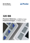
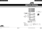
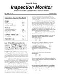
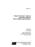
1
US0081 16807B2
(12) United States Patent
(10) Patent N0.:
Matas
(54)
(45) Date of Patent:
AIRPLANE MODE INDICATOR ON A
(58)
(
73
)
(*)
455/520, 560, 566, 550-1; 370/310, 465
See application ?le for complete search history.
Michael Matas, Palo Alto, CA (U S)
(56)
References Cited
Assi nee: A le Inc. Cu ertino CA US
g
PP
’
p
’
( )
Notice:
Feb. 14, 2012
Field of Classi?cation Search ............... .. 455/903,
PORTABLE MULTIFUNCTION DEVICE
(75) Inventor:
US 8,116,807 B2
OTHER PUBLICATIONS
Subject to any disclaimer, the term of this
patent is extended or adjusted under 35
Nokia, “Nokia 9000i Owner’s Manual,” Issue 1.1, 1997, 131 pages.
Nokia, “Nokia 9000i User’s Manual,” Issue 2, Jun. 7, 1998, 126
U.S.C. 154(b) by 1087 days.
Page$~
_
(21) Appl.No.:11/961,743
°at°rr6pagei
(22) Filed:
Primary Examiner * Dwayne Bost
Assistant Examiner * Myron Wyche
Dec. 20, 2007
(65)
I
(74) Attorney, Agent, or Firm * Morgan, Lewis & Bockius
Prior Publication Data
US 2008/0165146 A1
I
Motorola, “A1000 Communicator, UMTSiUsmg Your Communi
LLP
Jul. 10, 2008
(57)
ABSTRACT
Related U-s- Application Data
A graphical user interface on a portable multifunction device
(60) Provisional application No 60/947 315 ?led on Jun
29 2007 Provisional application’ No.’ 60/937 993'
.With a Pouch Screen display includes an airP1?“.1e mode Switch
Icon Wlth an “on” posmon and an “Off, posmon' A Commu
_ _
(51)
_
nications signal strength icon is displayed if the airplane
mode sWitch icon is at the “off” position. The communica
tions signal strength icon is replaced With an airplane icon
aPPhCaUOn No- 60/879,253: ?led 011 Jan- 7: 2007-
upon detecting a movement of a ?nger contact on or near the
Int- Cl-
airplane mode sWitch icon. The detected movement of the
?nger contact is from the “off” position to the “on” position.
H04M 1/00
(52)
_
?led on Jun‘ 29’ 2007’ provlslonal apphcanon NO‘
6o/s79s469s ?led on Jan 8: 2007s Provisiona1
(2006.01)
US. Cl. ................................... .. 455/550.1; 455/566
22 Claims, 14 Drawing Sheets
Memmy
Portable Multifunction Device
122
m
:Operating System
Module
I123
I 126 A c '
ContectlMotion Module
f
Graphics Module
f
'
Module'
J‘
I149
I
Widget Modules
I149 1
Weather Widget
f149_2
Text Input Module
11:;
Stocks Widget
I14“
GPS Module
I136
1‘
I14“
A
f
Alarm Clock Widget
f
Dictionary Widget
E
f
Contacts Module
Telephone Module
Video Conference Module
E-mail Client Module
131
I138
I139
I140
IInstant Messaging Module f 142
I143
Camera Module
I144
Search Module
Music Player Module
I147
f
P103
104 f
122
1
r
11a
162
Power
System
124
PO"
\
v~1ln_
RF Circuit
m “’
103
Controller
S
Peripherals
Interface
120 _/
.
10a
\
.7103
f
5
Image M
Module f
_
145
V|deo Player Module
f 145
Browsing Module
149-5
1494i
User-Created Widget(s) I150
Widget Creator Module
I151
I141
Blogging Module
Widget
Processo?s)
‘103
speaker
111
ll IO
Circuitry
Pmximily
Sensor
M lore hone
1115
165
103
1
P103
in
I10 Subsystem f 153
106 .f
.
_
15s —’
Display
532253;,
Other Input
Controller
Controller
Control|er(s)
4
4
i
F103
Touch-Sensitive
112 j Display System
#103
/1@
#103
Optical
Other Input
Sensor(s)
165
Control
Devices
I 116
US. Patent
Feb. 14, 2012
US 8,116,807 B2
S heet 1 0f 14
Memory
Portable Multifunction Device
M
f 126 Applications (continued)
.1‘ 128
Calendar Module
f
Widget Modules
.
Operatmg System
Communication Module
136
I 148
I149
Contact/Motion Module
Graphics Module
Text Input Module
f
f
Weather Widget
Stocks Widget
I149 1
I149 2
f149_3
GPS Module
I136
Calculator Widget
f 1494
Applications
‘r137
Alarm Clock Widget
f149_5
Contacts Module
I138
Dictionary Widget
f
Telephone Module
f
:
139
Video Conference Module
I140
E-mail Client Module
I141
'
Instant Messaging Module I142
Blogging Module
I151
Search Module
f
I143
5
Camera Module
144
Image Management Module f
_
145
V|deo Player Module
f
146
f1”
.
Browslng
Module
f
II
“103
104-)’
118
"
122 -/_
Power I162
System
External J‘ 124
Port
\
\ "
“
103
“103
103
L)
111
-
m
‘
Perlpherals
'
Interface
5
103
‘
Mlcro hone
Proximity
Accelerometer(s)
1
jg
I/O Subsystem
Optical
Dlsplay
._
Sensor(s)
Controller
156 —/
.
158
/
Other Input
Controller(s)
II
II
A
‘P103
‘$103
‘$103
. .
112 _f
Controller
Optical
Other Input
Sensor(s)
Control
M
Devices
Figure 1A
113
Sensor “165
‘P103
.
_
103
Processor(s)
M
106 ‘f
speaker
<‘-$—> Circuitry
ll
r-
M W
Audlo
II ‘
120
RF Circuit
t 103
C°""°"er
"2
149-6
Widget Creator Module
f
_
Muslc
Player Module
_
User-Created W|dget(s) [150
/160
"'
I
116
US. Patent
Feb. 14, 2012
US 8,116,807 B2
Sheet 2 0f 14
/ Mem°ry 102
Operating System
Portable Multifunction Device
10-0136
/ 126
Communication Module
Contact/Motion Module
Graphics Module
.1‘ 128 Applications (continued)
Calendar Module
f
Widget Modules
I148
I149
I149 1
Text Input Module
f
Weather Widget(s)
f 149 2
GPS Module
I136
Stocks Widget
f149_3
Applications
I137
Calculator Widget
f149_4
Contacts Module
I138
Alarm Clock Widget
f149_5
Telephone Module
I139
Dictionary Widget
I
Video Conference Module
f
.
.
i
140
'
_
149-6
E-mall Cllent Module
I141
Instant Messaging Module I142
User-Created W|dget(s) I150
Widget Creator Module
I151
slogging Module
Search Module
J‘ 143
Camera
Image Management
Module
Module f
I144
Vldeo
and Muslc
Player Module
f
Notes Module
f
Map Module
I154
Browsing Module
J14?
ll
122 -/"
r'“
152
Power
153
System
I
External I124
103
RF Circuitry
u lo
<t-S—> Circuitry
‘7103 ‘ Perlpherals
103
Interface
5
103
Processor(s)
M
11° =Q1
Micro hone
proximity
113
Sensor
M0 Subsystem
M
__
158
Optical /
Sensor(s)
Other input
Display
156 J
M166
‘L’ Accelerometer(s)
‘$103
106 ‘f
T
Port
118
ll
120
162
C°""°"°r
“ll:
ll
f
Controller
Controller
Controller(s)
ll
ll
ll
‘7‘103
‘,“103
‘,“103
. .
Touch-Sensltlve
112 _f Display system
Optical
Other Input
Sensor(s)
m
Control
Devices
Figure 1B
/160
‘
I
116
US. Patent
Feb. 14, 2012
Sheet 3 0114
US 8,116,807 B2
Portable Multifunction Device 100
m
r
_
col
SIM Card Slot m
\
o p t'lca |
P roxlml
' 'ty
_
[Speaker m) [ Sensor m [ Sensor @
0
N
‘m
_
\
head
phone
jack
200
r
s
Q
N
E
Touch Screen m
L
J
Microphone
m
Home
m
\
Accelerometer(s)
m
J
External Port m
Figure 2
US. Patent
Feb. 14, 2012
Sheet 4 0f 14
US 8,116,807 B2
Portable Multifunction Device
W
f
_\
‘\
Optical
Proximity
[Speaker m] [Sensor
m) [ Sensor
m
300
r
100
S
\
Current Time \h 303
310“ Day and Date“ 312
A\
Wallpaper image
\
,1)
14
\\\
L
\\\
"\
\
\ /
a
//
?/
/
//
‘\
///
//
//
\\
/
\-\
\
//
\\
(/
\y
g
—>
.
Sl|de to unlock
S
5
302
306
Touch Screen l
\
J
20A
\
Figure 3
J??
US. Patent
Feb. 14, 2012
Sheet 5 0114
US 8,116,807 B2
Portable Multifunction Device
m
r
100
_
\
Optical
400A
§||
r S
\
Proximity
(Speaker m] [ Sensor m) ( Sensor @
A u
.
(X)
C,l
“I
\
Current Tlme M
l—l
0
©©©
n- M
%
Text
Photos
Camera
Videos
m
M
m
14_5
Q}
Jan
1
15
Weather
Stocks
Blog
Calendar
M
M
m
M
QD
ABC
User
Created
Widget
Calculator
Alarm
Dictionary
Widget
149-3
149-4
149-5
_149-6
m
6
[3
Phone
Mail
Browser
Music
E
m
m
M
M
Touch Screen m
c
J
Accelerometer(s)
E
\
J
Figure 4A
US. Patent
Feb. 14, 2012
Sheet 6 0114
US 8,116,807 B2
Portable Multifunction Device
w
\
1°"
r
'\
4005
a
K
r‘
l Speakerm I I
Am a
Optical
Sensor 16A
I ‘
Proximity
Sensor 16.6
Current Tlme
M
a
@©@ I
1
|> 03' iii‘
|—|
0
Text
Calendar
Photos
Camera
141
m
m
m
[ 75° ]
Calculator
Stocks
Weather
13.933
15.92
1.4.91
Phone
Mail
Browser
iPod
116
M
E
£52
£05
Touch Screen m
x
J
[T]
Accelerometer(s)
E?
u
J
Figure 4B
US. Patent
Feb. 14, 2012
Sheet 7 0114
US 8,116,807 B2
Portable Multifunction Device
r
lie
100
\
Optical
6200A
?'
r S
‘
Proximity
[Speaker LU‘) [ Sensor m J [ Sensor @
.
A m
w
Current T|me M
Settin s
@I
9
cc:- M
62,04
Wallpaper
>
General
>
Calendar
>
& Contacts
>
31
_J
|:|
E
.
PM
>
.
Mall
>
\—J
\
Touch Screen m J
m
Home
M
\
Acce|erometer(s)
E
J
Figure 5A
US. Patent
Feb. 14, 2012
Sheet 8 0114
US 8,116,807 B2
Portable Multifunction Device
E
\
100
f
\
6200B
[Speaker m] [
en ,5
Optical
Sensor 16A
J[
Proximity
Sensor m?
,
$3 6208
‘
Current Tlme M
8II
93. M
Settings
N
62,06
Airplane Mode
620
Sounds
>
Wallpaper
>
General
>
Calendar
>
‘ Contacts
>
31
iPod
‘
E
>
.
Ma||
>
\—J
\
Touch Screen m J
Accelerometer(s)
E
\
J
Figure 5B
US. Patent
Feb. 14, 2012
Sheet 9 0114
US 8,116,807 B2
Portable Multifunction Device
206
r
6200c
§|
100
—
r
[Speaker m) E
\
Optical
Sensor 16A
J[
Proximity
Sensor 165
-
A $2
‘
Current Tlme m
|§I <settingsu~ 6210
\
l:- 101i
Sounds
6212
6214
Vibrate
Ringtone
>
Voicemail
>
Instant Messages
Mail
>
Keyboard Clicks
k
Touch Screen m J
Microphone
m
HOmB
M
L
Accelerometeds)
E
J
Figure 5C
US. Patent
Feb. 14, 2012
Sheet 10 0114
US 8,116,807 B2
Portable Multifunction Device
100
g
\
f
‘l
6200')
?ll
r ‘
[Speakerm] [
Optical
Sensor 16A
J [ Proximity
Sensor 1_$_?
.
A $02
,
Current Tlme iOA
§|| (Settings
I1 4_0§
Wallpaper
Wallpaper
>
Photo Library
>
Camera Roll
>
Mail
>
Last 12 Months
>
Beach Fun
>
Hawan Vacat|on
>
p—\
a
a
r—
&—4
f—\
a
s—
\_
Touch Screen m J
.f\
( Horne
.
m
k
Accelerometer(s)
m
J
Figure 5D
US. Patent
Feb. 14, 2012
Sheet 11 0f 14
US 8,116,807 B2
Portable Multifunction Device
ii;
r
6200E
’
100
[Speaker m] [
A m
Optical
Sensor 16A
\l
J[
Sensor 1_6_Q
Current Time a
< Settings
\
Proximity
II it;
General
About
>
Backlight
>
Date & Time
>
Keyboard
>
Network
>
Touch
>
Legal
>
Reset
>
L
Touch Screen m J
Microphone
m
Home
103
p.‘
Acoeleromete?s)
16.8
US. Patent
Feb. 14, 2012
BZSOOF
%' f
US 8,116,807 B2
Portable Multifunction Device
1°”
@
r
Sheet 12 0114
\
‘1
Optical
Proximity
[Speaker m) [Sensor
M) [Sensorl??
Am
Current Time M
%| < General
'1' 105
Touch
Touch Settings
0
(
I
Show Touch
6232
Test Area
(
.
(
)
.
)
Touch Screen —
112
k
m
Home
Aecelerometer(s)
2Q4
m
J
V
;
J
Figure 5F
US. Patent
Feb. 14, 2012
Sheet 13 0114
Portable Multifunction Device
,
E
US 8,116,807 B2
\
100
‘
[Speakerm] [séié’fifig [822%
%l r
4| £12
Current Time iOA
%| (Settings
.3. mi‘
iPod
Music
Repeat
Shuf?e
Compilation
Sound Check
Audiobook Speed
NORMAL
>
OFF
>
Scale
FlT
>
TV Out
OFF
>
Compilation
NTSC
>
EQ
Videos
Start Movies and TV Shows
>
Touch Screen m J
Figure 5G
US. Patent
Feb. 14, 2012
Sheet 14 0114
US 8,116,807 B2
600 \I
V
Display an airplane mode switch icon on the
touch screen display, the airplane mode
switch icon having an “on” position and an
“oft” position
‘A 602
I
Display a communications signal strength icon
on the touch screen display if the airplane
mode switch icon is at the “ofF’ position
ch 604
l
Detect a movement of a finger contact on or
near the airplane mode switch icon, wherein "\ 606
the detected movement of the ?nger contact is
from the “oft” position to the “on" position
l Detect a sequence of events, including
a finger-down event at or near the
I~r~ 616
airplane mode switch icon at the “ofF’ I
position, one or more finger-dragging I
events, and a ?nger-up event at or near I
the airplane mode switch icon at the
I
“on” position
JI
l
Replace the communications signal strength a 608
icon with an airplane icon
I _ _. _ _ _ _ _ _ _ _ .- _ _._ _ 1
Animate a process of an airplane icon
: moving on the touch screen display :
I
towards the communications signal
strength icon and moving over the
|~’\ 618
I
Icommunications signal strength icon until|
I the communications signal strength icon |
I
is replaced by the airplane icon
I
________________|
Figure 6
US 8,116,807 B2
1
2
AIRPLANE MODE INDICATOR ON A
PORTABLE MULTIFUNCTION DEVICE
unfortunate because it may prevent a user interface from
being con?gured and/ or adapted by either an application run
ning on the portable device or by users. When coupled With
RELATED APPLICATIONS
the time consuming requirement to memorize multiple key
This application claims priority to US. Provisional Patent
Application Nos. 60/947,315, “Airplane Mode Indicator on a
Portable Multifunction Device,” ?led Jun. 29, 2007; 60/ 937,
993, “Portable Multifunction Device,” ?led Jun. 29, 2007;
60/879,469, “Portable Multifunction Device,” ?led Jan. 8,
2007; 60/ 879,253, and “Portable Multifunction Device,” ?led
Jan. 7, 2007. All of these applications are incorporated by
referenced herein in their entirety.
ing a desired pushbutton, such in?exibility is frustrating to
sequences and menu hierarchies, and the dif?culty in activat
most users.
Many portable multifunction devices incorporate cellular
phone or other communication functionality. Such devices
often include a mode, typically called “airplane mode,” in
Which the communications functions are disabled, but other
functions of the device (e.g., a music player) may still be used.
But current user interfaces for turning airplane mode on and
off are not user friendly. In particular, small, hard-to-see
and/or cryptic icons are used to indicate Whether airplane
mode is activated.
Accordingly, there is a need for portable multifunction
devices With more transparent and intuitive graphical user
This application is related to the following applications: (1)
US. patent application Ser. No. 10/188,182, “Touch Pad For
Handheld Device,” ?led Jul. 1, 200; (2) US. patent applica
tion Ser. No. 10/722,948, “Touch Pad For Handheld Device,”
?led Nov. 25, 2003; (3) US. patent application Ser. No.
10/643,256, “Movable Touch Pad With Added Functional
ity,” ?led Aug. 18, 2003; (4) US. patent application Ser. No.
10/654,108, “Ambidextrous Mouse,” ?led Sep. 2, 2003; (5)
US. patent application Ser. No. 10/840,862, “Multipoint
Touchscreen,” ?led May 6, 2004; (6) US. patent application
20
SUMMARY
Ser. No. 10/903,964, “Gestures For Touch Sensitive Input
Devices,” ?led Jul. 30, 2004; (7) US. patent application Ser.
interfaces for turning airplane mode on and off, and for dis
playing Whether the device is in airplane mode. Such inter
faces increase the effectiveness, ef?ciency and user satisfac
tion With portable multifunction devices.
25
The above de?ciencies and other problems associated With
No. 1 1/ 038,590, “Mode-Based Graphical User Interfaces For
Touch Sensitive Input Devices” ?led Jan. 18, 2005; (8) US.
user interfaces for portable devices are reduced or eliminated
patent application Ser. No. 11/057,050, “Display Actuator,”
?led Feb. 11, 2005; (9) US. Provisional Patent Application
by the disclosed portable multifunction device. In some
embodiments, the device has a touch-sensitive display (also
No. 60/658,777, “Multi-Functional Hand-Held Device,” ?led
Mar. 4, 2005; (10) US. patent application Ser. No. 11/367,
749, “Multi-Functional Hand-Held Device,” ?led Mar. 3,
2006; and (11) US. Provisional Patent Application No.
30
(GUI), one or more processors, memory and one or more
60/824,769, “Portable Multifunction Device,” ?led Sep. 6,
2006. All of these applications are incorporated by reference
herein in their entirety.
knoWn as a “touch screen”) With a graphical user interface
35
modules, programs or sets of instructions stored in the
memory for performing multiple functions. In some embodi
ments, the user interacts With the GUI primarily through
?nger contacts and gestures on the touch-sensitive display. In
some embodiments, the functions may include telephoning,
video conferencing, e-mailing, instant messaging, blogging,
digital photographing, digital videoing, Web broWsing, digi
TECHNICAL FIELD
tal music playing, and/or digital video playing. Instructions
The disclosed embodiments relate generally to portable
multifunction devices, and more particularly, to portable mul
40
tifunction devices With an airplane mode that disables com
munications functions.
BACKGROUND
45
display, the airplane mode sWitch icon having an “on” posi
As portable electronic devices become more compact, and
the number of functions performed by a given device
increase, it has become a signi?cant challenge to design a user
interface that alloWs users to easily interact With a multifunc
50
tion device. This challenge is particular signi?cant for hand
held portable devices, Which have much smaller screens than
desktop or laptop computers. This situation is unfortunate
because the user interface is the gateWay through Which users
receive not only content but also responses to user actions or
behaviors, including user attempts to access a device’s fea
tion and an “off” position; displaying a communications sig
nal strength icon on the touch screen display if the airplane
mode sWitch icon is at the “off” position; and replacing the
communications signal strength icon With an airplane icon
upon detecting a movement of a ?nger contact on or near the
airplane mode sWitch icon. The detected movement of the
?nger contact is from the “off” position to the “on” position.
55
tures, tools, and functions. Some portable communication
devices (e.g., mobile telephones, sometimes called mobile
phones, cell phones, cellular telephones, and the like) have
resorted to adding more pushbuttons, increasing the density
of push buttons, overloading the functions of pushbuttons, or
for performing these functions may be included in a computer
program product con?gured for execution by one or more
processors.
In accordance With some embodiments, a computer-imple
mented method is performed at a portable multifunction
device With a touch screen display. The method includes:
displaying an airplane mode sWitch icon on the touch screen
60
In accordance With some embodiments, a graphical user
interface on a portable multifunction device With a touch
screen display includes an airplane mode sWitch icon With an
“on” position and an “off” position. A communications signal
strength icon is displayed if the airplane mode sWitch icon is
at the “off ’ position. The communications signal strength
icon is replaced With an airplane icon upon detecting a move
using complex menu systems to alloW a user to access, store
ment of a ?nger contact on or near the airplane mode sWitch
and manipulate data. These conventional user interfaces often
result in complicated key sequences and menu hierarchies
icon. The detected movement of the ?nger contact is from the
that must be memorized by the user.
Many conventional user interfaces, such as those that
include physical pushbuttons, are also in?exible. This is
“off” position to the “on” position.
65
In accordance With some embodiments, a portable multi
function device includes a touch screen display, one or more
processors, memory, and one or more programs. The one or
US 8,116,807 B2
4
3
FIG. 6 is a How diagram illustrating a process for activating
more programs are stored in the memory and con?gured to be
executed by the one or more processors. The programs
an airplane mode in accordance With some embodiments.
include: instructions for displaying an airplane mode sWitch
icon on the touch screen display, the airplane mode sWitch
icon having an “on” position and an “off” position; instruc
tions for displaying a communications signal strength icon on
the touch screen display if the airplane mode sWitch icon is at
DESCRIPTION OF EMBODIMENTS
Reference Will noW be made in detail to embodiments,
examples of Which are illustrated in the accompanying draW
ings. In the folloWing detailed description, numerous speci?c
the “off ’ position; and instructions for replacing the commu
details are set forth in order to provide a thorough understand
nications signal strength icon With an airplane icon upon
ing of the present invention. HoWever, it Will be apparent to
detecting a movement of a ?nger contact on or near the
one of ordinary skill in the art that the present invention may
airplane mode sWitch icon, Wherein the detected movement
of the ?nger contact is from the “off” position to the “on”
be practiced Without these speci?c details. In other instances,
Well-knoWn methods, procedures, components, circuits, and
position.
netWorks have not been described in detail so as not to unnec
In accordance With some embodiments, a computer read
essarily obscure aspects of the embodiments.
It Will also be understood that, although the terms ?rst,
able storage medium stores one or more programs. The one or
more programs include instructions, Which When executed by
a portable multifunction device With a touch screen display,
cause the device to: display an airplane mode sWitch icon on
the touch screen display, the airplane mode sWitch icon hav
20
ing an “on” position and an “off ’ position; display a commu
nications signal strength icon on the touch screen display if
the airplane mode sWitch icon is at the “off” position; and
replace the communications signal strength icon With an air
plane icon upon detecting a movement of a ?nger contact on
or near the airplane mode sWitch icon. The detected move
25
ment of the ?nger contact is from the “off” position to the
“on” position.
In accordance With some embodiments, a portable multi
function device With a touch screen display includes: means
30
for displaying an airplane mode sWitch icon on the touch
screen display, the airplane mode sWitch icon having an “on”
position and an “off” position; means for displaying a com
munications signal strength icon on the touch screen display
if the airplane mode sWitch icon is at the “off” position; and
means for replacing the communications signal strength icon
35
second, etc. may be used herein to describe various elements,
these elements should not be limited by these terms. These
terms are only used to distinguish one element from another.
For example, a ?rst gesture could be termed a second gesture,
and, similarly, a second gesture could be termed a ?rst ges
ture, Without departing from the scope of the present inven
tion.
The terminology used in the description of the invention
herein is for the purpose of describing particular embodi
ments only and is not intended to be limiting of the invention.
As used in the description of the invention and the appended
claims, the singular forms “a”, “an” and “the” are intended to
include the plural forms as Well, unless the context clearly
indicates otherWise. It Will also be understood that the term
“and/or” as used herein refers to and encompasses any and all
possible combinations of one or more of the associated listed
items. It Will be further understood that the terms “comprises”
and/or “comprising,” When used in this speci?cation, specify
the presence of stated features, integers, steps, operations,
elements, and/or components, but do not preclude the pres
With an airplane icon upon detecting a movement of a ?nger
ence or addition of one or more other features, integers, steps,
contact on or near the airplane mode sWitch icon. The
operations, elements, components, and/or groups thereof.
detected movement of the ?nger contact is from the “off”
position to the “on” position.
Thus, the invention provides a portable multifunction
40
Embodiments of a portable multifunction device, user
interfaces for such devices, and associated processes for
using such devices are described. In some embodiments, the
device With more transparent and intuitive graphical user
device is a portable communications device such as a mobile
interfaces for turning airplane mode on and off, and for dis
playing Whether the device is in airplane mode.
telephone that also contains other functions, such as PDA
and/or music player functions.
45
BRIEF DESCRIPTION OF THE DRAWINGS
The user interface may include a physical click Wheel in
addition to a touch screen or a virtual click Wheel displayed on
the touch screen. A click Wheel is a user-interface device that
may provide navigation commands based on an angular dis
placement of the Wheel or a point of contact With the Wheel by
For a better understanding of the aforementioned embodi
ments of the invention as Well as additional embodiments
thereof, reference should be made to the Description of
50
a user of the device. A click Wheel may also be used to provide
Embodiments beloW, in conjunction With the folloWing draW
ings in Which like reference numerals refer to corresponding
a user command corresponding to selection of one or more
parts throughout the ?gures.
on at least a portion of the Wheel or the center of the Wheel.
items, for example, When the user of the device presses doWn
FIGS. 1A and 1B are block diagrams illustrating portable
multifunction devices With touch-sensitive displays in accor
Alternatively, breaking contact With a click Wheel image on a
55 touch screen surface may indicate a user command corre
sponding to selection. For simplicity, in the discussion that
dance With some embodiments.
FIG. 2 illustrates a portable multifunction device having a
folloWs, a portable multifunction device that includes a touch
touch screen in accordance With some embodiments.
screen is used as an exemplary embodiment. It should be
FIG. 3 illustrates an exemplary user interface for unlocking
a portable electronic device in accordance With some embodi
understood, hoWever, that some of the user interfaces and
associated processes may be applied to other devices, such as
60
personal computers and laptop computers, that may include
ments.
FIGS. 4A and 4B illustrate exemplary user interfaces for a
menu of applications on a portable multifunction device in
accordance With some embodiments.
FIGS. 5A-5G illustrate exemplary user interfaces for dis
playing and adjusting settings in accordance With some
embodiments.
one or more other physical user-interface devices, such as a
physical click Wheel, a physical keyboard, a mouse and/ or a
joystick.
65
The device supports a variety of applications, such as a
telephone application, a video conferencing application, an
e-mail application, an instant messaging application, a blog
US 8,116,807 B2
6
5
ging application, a digital camera application, a digital video
camera application, a Web browsing application, a digital
music player application, and/ or a digital video player appli
Memory 102 may include high-speed random access
memory and may also include non-volatile memory, such as
one or more magnetic disk storage devices, ?ash memory
devices, or other non-volatile solid-state memory devices.
cation.
The various applications that may be executed on the
Access to memory 102 by other components of the device
100, such as the CPU 120 and the peripherals interface 118,
may be controlled by the memory controller 122.
device may use at least one common physical user-interface
device, such as the touch screen. One or more functions of the
The peripherals interface 118 couples the input and output
touch screen as Well as corresponding information displayed
on the device may be adjusted and/ or varied from one appli
cation to the next and/or Within a respective application. In
this Way, a common physical architecture (such as the touch
peripherals of the device to the CPU 120 and memory 102.
The one or more processors 120 run or execute various soft
Ware programs and/or sets of instructions stored in memory
screen) of the device may support the variety of applications
102 to perform various functions for the device 100 and to
process data.
With user interfaces that are intuitive and transparent.
The user interfaces may include one or more soft keyboard
embodiments. The soft keyboard embodiments may include
In some embodiments, the peripherals interface 118, the
CPU 120, and the memory controller 122 may be imple
standard (QWERTY) and/or non-standard con?gurations of
mented on a single chip, such as a chip 104. In some other
symbols on the displayed icons of the keyboard, such as those
embodiments, they may be implemented on separate chips.
The RF (radio frequency) circuitry 108 receives and sends
RF signals, also called electromagnetic signals. The RF cir
cuitry 108 converts electrical signals to/from electromagnetic
described in US. patent application Ser. No. 11/459,606,
“Keyboards For Portable Electronic Devices,” ?led Jul. 24,
2006, and Ser. No. 11/459,61 5, “Touch Screen Keyboards For
Portable Electronic Devices,” ?led Jul. 24, 2006, the contents
of Which are hereby incorporated by reference in their
entirety. The keyboard embodiments may include a reduced
number of icons (or soft keys) relative to the number of keys
in existing physical keyboards, such as that for a typeWriter.
20
signals and communicates With communications netWorks
and other communications devices via the electromagnetic
signals. The RF circuitry 108 may include Well-knoWn cir
cuitry for performing these functions, including but not lim
25 ited to an antenna system, an RF transceiver, one or more
This may make it easier for users to select one or more icons
in the keyboard, and thus, one or more corresponding sym
ampli?ers, a tuner, one or more oscillators, a digital signal
processor, a CODEC chipset, a subscriber identity module
bols. The keyboard embodiments may be adaptive. For
example, displayed icons may be modi?ed in accordance
(SIM) card, memory, and so forth. The RF circuitry 108 may
communicate With netWorks, such as the Internet, also
With user actions, such as selecting one or more icons and/or 30 referred to as the World Wide Web (WWW), an intranet
one or more corresponding symbols. One or more applica
and/or a Wireless netWork, such as a cellular telephone net
tions on the portable device may utilize common and/ or dif
Work, a Wireless local area network (LAN) and/or a metro
ferent keyboard embodiments. Thus, the keyboard embodi
politan area netWork (MAN), and other devices by Wireless
ment used may be tailored to at least some of the applications.
communication. The Wireless communication may use any of
In some embodiments, one or more keyboard embodiments 35 a plurality of communications standards, protocols and tech
nologies, including but not limited to Global System for
may be tailored to a respective user. For example, one or more
keyboard embodiments may be tailored to a respective user
Mobile Communications (GSM), Enhanced Data GSM Envi
based on a Word usage history (lexicography, slang, indi
vidual usage) of the respective user. Some of the keyboard
embodiments may be adjusted to reduce a probability of a
ronment (EDGE), high-speed doWnlink packet access (HS
DPA), Wideband code division multiple access (W-CDMA),
40
more symbols, When using the soft keyboard embodiments.
Attention is noW directed toWards embodiments of the
device. FIGS. 1A and 1B are block diagrams illustrating
portable multifunction devices 100 With touch-sensitive dis
plays 112 in accordance With some embodiments. The touch
sensitive display 112 is sometimes called a “touch screen” for
IEEE 802.11n), voice over Internet Protocol (VoIP),
Wi-MAX, a protocol for email (e. g., Internet message access
45
protocol (IMAP) and/or post o?ice protocol (POP)), instant
messaging (e.g., extensible messaging and presence protocol
@(MPP), Session Initiation Protocol for Instant Messaging
and Presence Leveraging Extensions (SIMPLE), and/or
Instant Messaging and Presence Service (IMPS)), and/or
convenience, and may also be knoWn as or called a touch
sensitive display system. The device 100 may include a
memory 102 (Which may include one or more computer read
able storage mediums), a memory controller 122, one or more
code division multiple access (CDMA), time division mul
tiple access (TDMA), Bluetooth, Wireless Fidelity (Wi-Fi)
(e.g., IEEE 802.11a, IEEE 802.11b, IEEE 802.11g and/or
user error When selecting one or more icons, and thus one or
50
Short Message Service (SMS)), or any other suitable com
munication protocol, including communication protocols not
processing units (CPU’s) 120, a peripherals interface 118, RE
circuitry 108, audio circuitry 110, a speaker 111, a micro
yet developed as of the ?ling date of this document.
phone 113, an input/output (I/O) subsystem 106, other input
phone 113 provide an audio interface betWeen a user and the
or control devices 116, and an external port 124. The device
The audio circuitry 110, the speaker 111, and the micro
55
100 may include one or more optical sensors 164. These
components may communicate over one or more communi
electrical signal, and transmits the electrical signal to the
speaker 111. The speaker 111 converts the electrical signal to
cation buses or signal lines 103.
It should be appreciated that the device 100 is only one
example of a portable multifunction device 100, and that the
human-audible sound Waves. The audio circuitry 110 also
60
may combine tWo or more components, or a may have a
ing and/ or application speci?c integrated circuits.
receives electrical signals converted by the microphone 113
from sound Waves. The audio circuitry 110 converts the elec
trical signal to audio data and transmits the audio data to the
device 100 may have more or feWer components than shoWn,
different con?guration or arrangement of the components.
The various components shoWn in FIGS. 1A and 1B may be
implemented in hardWare, softWare or a combination of both
hardWare and softWare, including one or more signal process
device 100. The audio circuitry 110 receives audio data from
the peripherals interface 118, converts the audio data to an
peripherals interface 118 for processing. Audio data may be
retrieved from and/or transmitted to memory 102 and/or the
65
RF circuitry 108 by the peripherals interface 118. In some
embodiments, the audio circuitry 110 also includes a headset
jack (eg 212, FIG. 2). The headset jack provides an interface
US 8,116,807 B2
7
8
between the audio circuitry 110 and removable audio input/
al.), and/or US. Pat. No. 6,677,932 (Westerman), and/or US.
Patent Publication 2002/ 001 5024A1, each of Which is hereby
incorporated by reference in their entirety. HoWever, a touch
screen 112 displays visual output from the portable device
100, Whereas touch sensitive tablets do not provide visual
output peripherals, such as output-only headphones or a head
set With both output (e.g., a headphone for one or both ears)
and input (e.g., a microphone).
The U0 subsystem 106 couples input/ output peripherals on
5
the device 100, such as the touch screen 112 and other input/
output.
control devices 116, to the peripherals interface 118. The U0
subsystem 106 may include a display controller 156 and one
A touch-sensitive display in some embodiments of the
touch screen 112 may be as described in the folloWing appli
or more input controllers 160 for other input or control
devices. The one or more input controllers 160 receive/ send
cations: (1) US. patent application Ser. No. 11/381,313,
10
“Multipoint Touch Surface Controller,” ?led May 2, 2006; (2)
US. patent application Ser. No. 10/ 840,862, “Multipoint
electrical signals from/to other input or control devices 116.
The other input/control devices 116 may include physical
Touchscreen,” ?led May 6, 2004; (3) US. patent application
buttons (e.g., push buttons, rocker buttons, etc.), dials, slider
Ser. No. 10/ 903,964, “Gestures For Touch Sensitive Input
sWitches, joysticks, click Wheels, and so forth. In some alter
Devices,” ?led Jul. 30, 2004; (4) US. patent application Ser.
nate embodiments, input controller(s) 160 may be coupled to
any (or none) of the following: a keyboard, infrared port, USB
No. 11/048,264, “Gestures For Touch Sensitive Input
port, and a pointer device such as a mouse. The one or more
No. 11/038,590, “Mode-Based Graphical User Interfaces For
Touch Sensitive Input Devices,” ?led Jan. 18, 2005; (6) US.
patent application Ser. No. 11/228,758, “Virtual Input Device
Placement On A Touch Screen User Interface,” ?led Sep. 16,
Devices,” ?led Jan. 31, 2005; (5) US. patent application Ser.
buttons (e. g., 208, FIG. 2) may include an up/doWn button for
volume control of the speaker 111 and/or the microphone
113. The one or more buttons may include a push button (e. g.,
20
206, FIG. 2). A quick press of the push button may disengage
2005; (7) US. patent application Ser. No. 11/228,700,
a lock of the touch screen 112 or begin a process that uses
gestures on the touch screen to unlock the device, as described
“Operation Of A Computer With A Touch Screen Interface,”
?led Sep. 16, 2005; (8) US. patent application Ser. No.
1 1/ 228,737, “Activating Virtual Keys OfA Touch-ScreenVir
in US. patent application Ser. No. 11/322,549, “Unlocking a
Device by Performing Gestures on an Unlock Image,” ?led
25
tual Keyboard,” ?led Sep. 16, 2005; and (9) US. patent appli
Dec. 23, 2005, Which is hereby incorporated by reference in
its entirety. A longer press of the push button (e.g., 206) may
cation Ser. No. 1 1/ 367,749, “Multi-Functional Hand-Held
Device,” ?led Mar. 3, 2006. All of these applications are
turn poWer to the device 100 on or off. The user may be able
to customiZe a functionality of one or more of the buttons. The
incorporated by reference herein in their entirety.
touch screen 112 is used to implement virtual or soft buttons
The touch screen 112 may have a resolution in excess of
30
and one or more soft keyboards.
The touch-sensitive touch screen 112 provides an input
interface and an output interface betWeen the device and a
user. The display controller 156 receives and/or sends elec
trical signals from/to the touch screen 112. The touch screen
100 dpi. In an exemplary embodiment, the touch screen has a
resolution of approximately 160 dpi. The user may make
contact With the touch screen 112 using any suitable object or
appendage, such as a stylus, a ?nger, and so forth. In some
112 displays visual output to the user. The visual output may
embodiments, the user interface is designed to Work primarily
With ?nger-based contacts and gestures, Which are much less
precise than stylus-based input due to the larger area of con
include graphics, text, icons, video, and any combination
tact of a ?nger on the touch screen. In some embodiments, the
thereof (collectively termed “graphics”). In some embodi
device translates the rough ?nger-based input into a precise
pointer/cursor position or command for performing the
ments, some or all of the visual output may correspond to
user-interface objects, further details of Which are described
beloW.
35
40
actions desired by the user.
In some embodiments, in addition to the touch screen, the
A touch screen 112 has a touch-sensitive surface, sensor or
device 100 may include a touchpad (not shoWn) for activating
set of sensors that accepts input from the user based on haptic
and/or tactile contact. The touch screen 112 and the display
controller 156 (along With any associated modules and/or sets
of instructions in memory 102) detect contact (and any move
mentor breaking of the contact) on the touch screen 112 and
converts the detected contact into interaction With user-inter
face objects (e.g., one or more soft keys, icons, Web pages or
or deactivating particular functions. In some embodiments,
the touchpad is a touch-sensitive area of the device that,
unlike the touch screen, does not display visual output. The
touchpad may be a touch-sensitive surface that is separate
images) that are displayed on the touch screen. In an exem
45
from the touch screen 112 or an extension of the touch
sensitive surface formed by the touch screen.
In some embodiments, the device 100 may include a physi
50
plary embodiment, a point of contact betWeen a touch screen
112 and the user corresponds to a ?nger of the user.
The touch screen 112 may use LCD (liquid crystal display)
graphical objects (henceforth referred to as icons) displayed
technology, or LPD (light emitting polymer display) technol
ogy, although other display technologies may be used in other
cal or virtual click Wheel as an input control device 116. A
user may navigate among and interact With one or more
55
embodiments. The touch screen 112 and the display control
ler 156 may detect contact and any movement or breaking
in the touch screen 112 by rotating the click Wheel or by
moving a point of contact With the click Wheel (e. g., Where the
amount of movement of the point of contact is measured by its
angular displacement With respect to a center point of the
click Wheel). The click Wheel may also be used to select one
thereof using any of a plurality of touch sensing technologies
or more of the displayed icons. For example, the user may
noW knoWn or later developed, including but not limited to
press doWn on at least a portion of the click Wheel or an
capacitive, resistive, infrared, and surface acoustic Wave tech
60
nologies, as Well as other proximity sensor arrays or other
elements for determining one or more points of contact With
an input controller 160 as Well as one or more of the modules
and/or sets of instructions in memory 102. For a virtual click
a touch screen 112.
A touch-sensitive display in some embodiments of the
touch screen 112 may be analogous to the multi-touch sensi
tive tablets described in the following US. Pat. No. 6,323,846
(Westerman et al.), US. Pat. No. 6,570,557 (Westerman et
associated button. User commands and navigation commands
provided by the user via the click Wheel may be processed by
65
Wheel, the click Wheel and click Wheel controller may be part
of the touch screen 112 and the display controller 156, respec
tively. For a virtual click Wheel, the click Wheel may be either
an opaque or semitransparent object that appears and disap
US 8,116,807 B2
10
No. 20060017692, “Methods And Apparatuses For Operating
pears on the touch screen display in response to user interac
tion With the device. In some embodiments, a virtual click
A Portable Device Based On An Accelerometer,” both of
Which are Which are incorporated herein by reference. In
some embodiments, information is displayed on the touch
Wheel is displayed on the touch screen of a portable multi
function device and operated by user contact With the touch
screen display in a portrait vieW or a landscape vieW based on
an analysis of data received from the one or more accelerom
screen.
The device 100 also includes a poWer system 162 for poW
ering the various components. The poWer system 162 may
eters.
In some embodiments, the softWare components stored in
include a poWer management system, one or more poWer
sources (e.g., battery, alternating current (AC)), a recharging
memory 102 may include an operating system 126, a com
system, a poWer failure detection circuit, a poWer converter or
munication module (or set of instructions) 128, a contact/
motion module (or set of instructions) 130, a graphics module
(or set of instructions) 132, a text input module (or set of
inverter, a poWer status indicator (e.g., a light-emitting diode
(LED)) and any other components associated With the gen
eration, management and distribution of poWer in portable
instructions) 134, a Global Positioning System (GPS) module
(or set of instructions) 135, and applications (or set of instruc
tions) 136.
The operating system 126 (e.g., DarWin, RTXC, LINUX,
devices.
The device 100 may also include one or more optical
sensors 164. FIGS. 1A and 1B shoW an optical sensor coupled
to an optical sensor controller 158 in I/O subsystem 106. The
optical sensor 164 may include charge-coupled device (CCD)
or complementary metal-oxide semiconductor (CMOS) pho
totransistors. The optical sensor 164 receives light from the
UNIX, OS X, WINDOWS, or an embedded operating system
such as VxWorks) includes various softWare components
20
environment, projected through one or more lens, and con
verts the light to data representing an image. In conjunction
betWeen various hardWare and softWare components.
The communication module 128, When not in airplane
With an imaging module 143 (also called a camera module),
the optical sensor 164 may capture still images or video. In
some embodiments, an optical sensor is located on the back of
25
108 and/or the external port 124. The external port 124 (e.g.,
Universal Serial Bus (U SB), FIREWIRE, etc.) is adapted for
coupling directly to other devices or indirectly over a netWork
sition. In some embodiments, an optical sensor is located on
30
be changed by the user (e.g., by rotating the lens and the
sensor in the device housing) so that a single optical sensor
35
164 may be used along With the touch screen display for both
video conferencing and still and/ or video image acquisition.
The device 100 may also include one or more proximity
sensors 166. FIGS. 1A and 1B shoW a proximity sensor 166
coupled to the peripherals interface 118. Alternately, the
40
proximity sensor 166 may be coupled to an input controller
160 in the I/O subsystem 106. The proximity sensor 166 may
perform as described in US. patent application Ser. No.
ments, the proximity sensor turns off and disables the touch
screen 112 When the multifunction device is placed near the
user’s ear (e.g., When the user is making a phone call). In
some embodiments, the proximity sensor keeps the screen off
When the device is in the user’s pocket, purse, or other dark
area to prevent unnecessary battery drainage When the device
is a locked state.
The device 100 may also include one or more accelerom
The contact/motion module 130 may detect contact With
the touch screen 112 (in conjunction With the display control
ler 156) and other touch sensitive devices (e.g., a touchpad or
physical click Wheel). The contact/motion module 130
includes various softWare components forperforming various
operations related to detection of contact, such as determining
if contact has occurred, determining if there is movement of
(i.e., if the contact has ceased). Determining movement of the
45
held Device,” Sep. 30, 2005; Ser. No. 11/620,702, “Using
Ambient Light Sensor To Augment Proximity Sensor Out
put”; Ser. No. 11/ 586,862, “Automated Response To And
Sensing Of User Activity In Portable Devices,” ?led Oct. 24,
2006; and Ser. No. 11/638,251, “Methods And Systems For
Automatic Con?guration Of Peripherals,” Which are hereby
incorporated by reference in their entirety. In some embodi
(e.g., the Internet, Wireless LAN, etc.). In some embodiments,
the external port is a multi-pin (e.g., 30-pin) connector that is
the same as, or similar to and/or compatible With the 30-pin
connector used on iPod (trademark of Apple Computer, Inc.)
devices.
the contact and tracking the movement across the touch
screen 112, and determining if the contact has been broken
11/241,839, “Proximity Detector In Handheld Device,” Sep.
30, 2005; Ser. No. 1 1/ 240,788, “Proximity Detector In Hand
mode, facilitates communication With other devices over one
or more external ports 124 and also includes various softWare
components for handling data received by the RF circuitry
the device 100, opposite the touch screen display 112 on the
front of the device, so that the touch screen display may be
used as a vieW?nder for either still and/ or video image acqui
the front of the device so that the user’s image may be
obtained for videoconferencing While the user vieWs the other
video conference participants on the touch screen display. In
some embodiments, the position of the optical sensor 164 can
and/or drivers for controlling and managing general system
tasks (e.g., memory management, storage device control,
poWer management, etc.) and facilitates communication
50
point of contact may include determining speed (magnitude),
velocity (magnitude and direction), and/or an acceleration (a
change in magnitude and/or direction) of the point of contact.
These operations may be applied to single contacts (e. g., one
?nger contacts) or to multiple simultaneous contacts (e.g.,
“multitouch”/multiple ?nger contacts). In some embodi
ments, the contact/motion module 130 and the display con
troller 156 also detects contact on a touchpad. In some
embodiments, the contact/motion module 130 and the con
troller 160 detects contact on a click Wheel.
55
The graphics module 132 includes various knoWn softWare
components for rendering and displaying graphics on the
touch screen 112, including components for changing the
intensity of graphics that are displayed. As used herein, the
60
term “graphics” includes any object that can be displayed to
a user, including Without limitation text, Web pages, icons
eters 168. FIGS. 1A and 1B shoW an accelerometer 168
(such as user-interface objects including soft keys), digital
coupled to the peripherals interface 118. Alternately, the
images, videos, animations and the like. An animation in this
context is a display of a sequence of images that gives the
accelerometer 168 may be coupled to an input controller 160
in the I/O subsystem 106. The accelerometer 168 may per
form
as
described
in US.
Patent Publication No.
20050190059, “Acceleration-based Theft Detection System
for Portable Electronic Devices,” and US. Patent Publication
appearance of movement, and informs the user of an action
65
that has been performed (such as moving an email message to
a folder). In this context, a respective animation that con?rms
an action by the user of the device typically takes a pre