1
Service Manual –
Serviceanleitung
320 BB
Precision Balances, s/n 5000000 and higher
Präzisionswaagen, s/n 5000000 und höher
320 BB
Identification – Identifikation
Service manual 320, Precision balances, s/n 5000000 and higher
350-8100 e1
June 2012
Subject to technical modifications
Serviceanleitung 320, Präzisionswaagen, s/n 5000000 und höher
350-8100 e1
Juni 2012
Technische Änderungen vorbehalten
www.precisa.com
Copyright
No reproduction in any form of this document, in whole or in part, may be made without written
authorization from Precisa Gravimetrics AG.
Ohne schriftliche Genehmigung der Precisa Gravimetrics AG darf diese Anleitung weder ganz noch
teilweise nachgedruckt oder vervielfältigt werden.
© Precisa Gravimetrics AG, 8953 Dietikon, Switzerland, 2012
A. MMDCCLXVO A.V.C. ROMANVS EMONENSIS FECIT
1
320 BB
Table of contents – Inhaltsverzeichnis
Table of contents – Inhaltsverzeichnis
1
Components – Bestandteile ..................................................................................................... 6
1.1
1.2
1.3
1.4
1.5
1.5.1
1.5.2
1.5.3
1.6
1.7
1.8
1.9
1.10
1.11
1.12
1.13
1.14
1.15
1.16
1.17
1.18
1.19
1.20
About spare parts – Über Ersatzteile ............................................................................ 6
Balance groups – Waagengruppen ............................................................................... 7
Housing's bottom – Gehäuseunterteil ........................................................................... 8
Housing's top – Gehäuseoberteil .................................................................................. 9
Weighing cell – Wägezelle ......................................................................................... 11
Overall view – Übersicht ........................................................................................... 11
Flexure repair sets – Lager-Reparatursets ................................................................... 13
Particular spare flexures – Jeweilige Ersatz-Lager ........................................................ 13
Weighing pan D80 Group A2 – Waagschale D80 Gruppe A2 .......................................... 14
Weighing pan 135, Group M – Waagschale 135, Gruppe M ............................................ 14
Weighing pan 170, Group C – Waagschale 170, Gruppe C............................................. 15
Weighing pan 200, Group D – Waagschale 200, Gruppe D ............................................ 16
Draftshield, XT – Windschutz, XT ............................................................................... 17
Draftshield 180, XB – Windschutz 180, XB .................................................................. 19
Draftshield 260, XB – Windschutz 260, XB .................................................................. 21
Draftshield easy – Windschutz einfach ........................................................................ 23
Draft deflector M – Windabweiser M ........................................................................... 24
Twin Reference Weight Device – Zwillings-Referenzgewichts-Modul ............................... 25
Main board – Hauptprint ........................................................................................... 26
Connector board – Steckerprint ................................................................................. 26
Display board VFD – Anzeigeprint VFD ....................................................................... 27
Universal switching power adapter – Universal-Schaltnetzteil ........................................ 28
Universal switching power adapter IP65 – Universal-Schaltnetzteil IP65 ......................... 28
2
Repairs .................................................................................................................................... 29
2.1
2.1.1
2.1.2
2.1.3
2.1.4
2.1.5
2.2
2.2.1
2.2.2
2.3
2.4
2.4.1
2.4.2
2.4.3
2.4.4
2.4.5
2.5
2.5.1
2.5.2
2.6
2.6.1
2.6.2
2.6.3
2.7
2.7.1
2.7.2
2.7.3
2.7.4
Before you get started.............................................................................................. 29
Proceeding .............................................................................................................. 29
About these instructions ........................................................................................... 29
Required tools ......................................................................................................... 30
Prepairing the tools .................................................................................................. 31
Spare parts ............................................................................................................. 31
Opening the balance ................................................................................................ 32
Opening the balance ................................................................................................ 32
Opening the IP65 balance ......................................................................................... 32
Removing the weighing cell from the housing‘s bottom................................................. 33
Dismantling the weighing cell .................................................................................... 34
Removing the coupling ............................................................................................. 34
Removing the 2 flexure holders ................................................................................. 34
Removing the coil .................................................................................................... 34
Removing the support piece ...................................................................................... 34
Removing the balance arm ....................................................................................... 35
Exchanging the horizontal flexures ............................................................................. 36
Removing the old horizontal flexures .......................................................................... 36
Installing new horizontal flexures............................................................................... 36
Cleaning ................................................................................................................. 37
Cleaning the magnet pot .......................................................................................... 37
Cleaning the coil ...................................................................................................... 37
Checking the cleanliness again .................................................................................. 37
Assembling the weighing cell..................................................................................... 38
Assembling the balance arm ..................................................................................... 38
Assembling the coil, the magnet cover and the transport safety device .......................... 38
Assembling the floating sensor and the stopper ........................................................... 39
Assembling new vertical flexures ............................................................................... 40
2
320 BB
Table of contents – Inhaltsverzeichnis
2.7.5
2.7.6
2.7.7
2.7.8
2.8
Assembling the support piece and the inner cone ........................................................ 41
Assembling the flexure holders .................................................................................. 42
Assembling a new coupling ....................................................................................... 43
Dismantling the assembly jigs ................................................................................... 43
Installing the weighing cell into the housing‘s bottom ................................................... 44
3
Adjustments ............................................................................................................................ 45
3.1
3.1.1
3.1.2
3.2
3.3
3.4
3.5
3.5.1
3.5.2
3.5.3
3.6
3.6.1
3.6.2
3.7
3.8
3.8.1
3.8.2
3.9
3.9.1
3.9.2
3.9.3
3.10
3.10.1
3.10.2
3.10.3
3.10.4
3.11
3.11.1
3.11.2
3.11.3
3.11.4
3.12
3.13
3.13.1
3.13.2
3.13.3
3.14
Before you get started.............................................................................................. 45
Table of specifications .............................................................................................. 45
Placing loads ........................................................................................................... 45
Setting the balance to the factory mode (the balance is open) ...................................... 45
Adjusting the symmetry ........................................................................................... 46
Checking the pre-load .............................................................................................. 46
Adjusting the corner load .......................................................................................... 47
Determining the corner load values ............................................................................ 47
Adjusting the corner load (Group M/C/D) .................................................................... 48
Adjusting the corner load (Group A) ........................................................................... 49
Checking the lowering process of the internal reference weights (SCS only) .................... 52
Checking the lowering process of the internal reference weights (10-Key version only) .... 52
Checking the lowering process of the internal reference weights (5-Key version only) ...... 52
Closing the balance .................................................................................................. 53
Setting the balance to the service mode (the balance is closed) .................................... 54
Setting the balance to the service mode (10-Key version only)...................................... 54
Setting the balance to the service mode (5-Key version only) ....................................... 54
Adjusting the linearity .............................................................................................. 55
Adjusting the linearity (10-Key version only)............................................................... 55
Adjusting the linearity (5-Key version only) ................................................................ 55
Checking the linearity............................................................................................... 56
Checking the adjustments of the closed balance .......................................................... 56
Checking the repeatability (with SCS) ........................................................................ 56
Checking the repeatability (without SCS) .................................................................... 56
Checking the corner load .......................................................................................... 57
Checking the linearity............................................................................................... 57
Adjusting the S-correction ........................................................................................ 58
Measuring the S-curve ............................................................................................. 58
Calculating the S-correction factors ............................................................................ 58
Entering the S-correction factors (10-Key version only) ................................................ 58
Entering the S-correction factors (5-Key version only).................................................. 59
Adjusting the internal reference weight (SCS only) ...................................................... 59
Error messages ....................................................................................................... 60
Operating errors; Error disappears by correct use or application .................................... 60
Fatal errors; Balance stays still, error remediable in service mode ................................. 60
Hardware errors; Balance stays still ........................................................................... 60
Discussion with the manufacturer .............................................................................. 61
4
Reparatur ................................................................................................................................ 62
4.1
4.1.1
4.1.2
4.1.3
4.1.4
4.1.5
4.2
4.2.1
4.2.2
4.3
4.4
Bevor Sie beginnen .................................................................................................. 62
Vorgehen ................................................................................................................ 62
Über diese Anleitung ................................................................................................ 62
Benötigtes Werkzeug ............................................................................................... 63
Vorbereiten des Werkzeugs ....................................................................................... 64
Ersatzteile .............................................................................................................. 64
Die Waage öffnen .................................................................................................... 65
Die Waage öffnen .................................................................................................... 65
Die IP65-Waage öffnen............................................................................................. 65
Die Wägezelle aus dem Gehäuseunterteil herausnehmen .............................................. 66
Die Wägezelle zerlegen ............................................................................................ 67
3
320 BB
Table of contents – Inhaltsverzeichnis
4.4.1
4.4.2
4.4.3
4.4.4
4.4.5
4.5
4.5.1
4.5.2
4.6
4.6.1
4.6.2
4.6.3
4.7
4.7.1
4.7.2
4.7.3
4.7.4
4.7.5
4.7.6
4.7.7
4.7.8
4.8
Das Zugband ausbauen ............................................................................................ 67
Die beiden Lenker ausbauen ..................................................................................... 67
Die Spule ausbauen ................................................................................................. 67
Den Träger ausbauen ............................................................................................... 67
Den Waagbalken ausbauen ....................................................................................... 68
Die Biegelager ersetzen ............................................................................................ 69
Die alten Biegelager entfernen .................................................................................. 69
Neue Biegelager anbringen ....................................................................................... 69
Reinigung ............................................................................................................... 70
Den Magnettopf reinigen .......................................................................................... 70
Die Spule reinigen ................................................................................................... 70
Die Sauberkeit nochmals überprüfen .......................................................................... 70
Die Wägezelle zusammenbauen ................................................................................. 71
Den Waagbalken einbauen ........................................................................................ 71
Die Spule, den Magnetdeckel und die Transportsicherung einbauen ............................... 71
Die Lichtschranke einbauen und den Anschlag einstellen .............................................. 72
Neue Hängelager einbauen ....................................................................................... 73
Den Träger, den Innenkonus und die Gewichtshalter einbauen ...................................... 74
Die Lenker einbauen ................................................................................................ 75
Ein neues Zugband einbauen .................................................................................... 76
Die Montagelehren entfernen .................................................................................... 76
Die Wägezelle ins Gehäuse-Unterteil einbauen ............................................................ 77
5
Justierung............................................................................................................................... 78
5.1
5.1.1
5.1.2
5.2
5.3
5.4
5.5
5.5.1
5.5.2
5.5.3
5.6
5.6.1
5.6.2
5.7
5.8
5.8.1
5.8.2
5.9
5.9.1
5.9.2
5.9.3
5.10
5.10.1
5.10.2
5.10.3
5.10.4
5.11
5.11.1
5.11.2
5.11.3
5.11.4
5.12
5.13
5.13.1
5.13.2
Bevor Sie beginnen .................................................................................................. 78
Spezifikationstabelle ................................................................................................ 78
Lasten auflegen ....................................................................................................... 78
Die Waage in den Werksmodus bringen (die Waage ist offen) ....................................... 78
Die Symmetrie justieren ........................................................................................... 79
Die Vorlast überprüfen ............................................................................................. 79
Die Eckenlast justieren ............................................................................................. 80
Die Eckenlastwerte ermitteln ..................................................................................... 80
Die Eckenlast justieren (Gruppe M/C/D) ..................................................................... 81
Die Eckenlast justieren (Gruppe A) ............................................................................ 82
Das Absenken des internen Referenzgewichts überprüfen (nur SCS) .............................. 85
Das Absenken der internen Referenzgewichte überprüfen (nur 10-Tasten-Ausführung) .... 85
Das Absenken der internen Referenzgewichte überprüfen (nur 5-Tasten-Ausführung) ...... 85
Die Waage schliessen ............................................................................................... 86
Die Waage in den Servicemodus bringen (die Waage ist geschlossen) ............................ 87
Die Waage in den Servicemodus bringen (nur 10-Tasten-Ausführung) ............................ 87
Die Waage in den Servicemodus bringen (nur 5-Tasten-Ausführung) ............................. 87
Die Linearität justieren ............................................................................................. 88
Die Linearität justieren (nur 10-Tasten-Ausführung) .................................................... 88
Die Linearität justieren (nur 5-Tasten-Ausführung) ...................................................... 88
Die Linearität überprüfen .......................................................................................... 89
Die Justierung der geschlossenen Waage überprüfen ................................................... 89
Die Wiederholbarkeit überprüfen (mit SCS) ................................................................. 89
Die Wiederholbarkeit überprüfen (ohne SCS) .............................................................. 89
Die Eckenlast überprüfen .......................................................................................... 90
Die Linearität überprüfen .......................................................................................... 90
Die S-Korrektur justieren .......................................................................................... 91
Die S-Kurve ausmessen ............................................................................................ 91
Die S-Korrekturfaktoren bestimmen ........................................................................... 91
Die S-Korrekturfaktoren eingeben (nur 10-Tasten-Ausführung) ..................................... 91
Die S-Korrekturfaktoren eingeben (nur 5-Tasten-Ausführung) ....................................... 92
Das interne Referenzgewicht justieren (nur SCS) ......................................................... 92
Fehlermeldungen ..................................................................................................... 93
Bedienungsfehler; Fehler verschwindet bei korrekter Bedienung bzw. Anwendung ........... 93
Fatale Fehler; Waage bleibt stehen, Abhilfe im Servicemodus ........................................ 93
4
320 BB
5.13.3
5.14
Table of contents – Inhaltsverzeichnis
Hardware-Fehler; Waage bleibt stehen ....................................................................... 93
Rücksprache mit dem Hersteller ................................................................................ 94
5
320 BB
Components – Bestandteile
1
Components – Bestandteile
1.1
About spare parts – Über Ersatzteile
•
Certain spare parts (e.g. flexures) have to be determined more precisely because of the various
capacities of balances. Therefore refer to the following table and find out to which group a
balance belongs.
Example: A 620M belongs to group M1. Thus, in group specific spare parts select the ones of
group M1.
Bestimmte Ersatzteile (z.B. Biegelager) müssen aufgrund verschiedener Tragfähigkeiten der
Waagen näher bestimmt werden. Hierfür ist mit Hilfe der folgenden Tabelle herauszufinden,
welcher Gruppe die Waage angehört.
Beispiel: Eine 620M gehört in die Gruppe M1. Bei gruppenspezifischen Ersatzteilen ist also
dasjenige der Gruppe M1 zu nehmen.
•
N instead of an article number means "Not available as spare part".
N anstelle der Artikelnummer bedeutet "Nicht als Ersatzteil erhältlich".
6
320 BB
1.2
Components – Bestandteile
Balance groups – Waagengruppen
Group Model
A1
600M-Carat
A2
220A
120A
1100M-Carat
220A-FR
M1
620M
420M
320M
220M
160M
3100C-Carat
620M-FR
M2
1220M
1220M-FR
2220M-DR
920M
C1
620C
320C
C2
2200C
1200C
C3
6200C
4200C
3200C
6200C-FR
4200C-FR
D1
6200D
3200D
6200D-FR
D2
10200D
8200D
10200G
10200D-FR
7
320 BB
1.3
Components – Bestandteile
Housing's bottom – Gehäuseunterteil
Pos. Pcs. Article number
Article
Artikel
1
2
3
4
5
6
7
8
9
10
11
12
13
14
15
16
17
Housing's bottom
Cover
Adhesive for bubble level
Levelling foot
Symmetry screw
Connector board
Pressure compensation cone, IP65
Screw cyl. Phillips M3x6
Screw cyl. Phillips M3x4
Screw cyl. Inbus M3x6
Screw cyl. Torx M4x6
Spring washer M3
Washer M5
Rivscrew
Bubble level
Main board
Display board VFD
Gehäuseunterteil
Abdeckblech
Kleber für Libelle
Stellfuss
Symmetrieschraube
Steckerprint
Druckausgleichszapfen, IP65
ZK-Schraube M3x6
ZK-Schraube M3x4
ZI-Schraube M3x6
ZT-Schraube M4x6
Federring M3
Unterlagsscheibe M5
Gewindeblindniete
Libelle
Hauptprint
Anzeigeprint VFD
1
1
1
2
2
1
1
4
2
1
6
2
1
1
1
1
1
320-7143
320-2010
320-4056
320-7015
240-4048
see page 26
PN 1056-001
PN 1100-023
PN 1100-060
PN 1100-162
PN 1100-169
PN 1500-018
PN 1500-074
PN 1700-034
PN 3730-001
see page 26
see page 27
8
320 BB
1.4
Components – Bestandteile
Housing's top – Gehäuseoberteil
Pos. Pcs. Article number
Article
1
2
3
5
6
7
8
9
10
4
Housing‘s top
Gehäuseoberteil
Display glass
Anzeigeglas
Membrane keypad, XB, swiss design Folientastatur, XB, swiss design
Protective ring, M/C
Schutzring, M/C
Protective cover terminal, 20 pcs
Schutzabdeckung Terminal, 20 Stk
Screw cyl. Phillips M4x25
ZK-Schraube M4x25
Screw cyl. slot M4x12
ZS-Schraube M4x12
Screw cyl. slot M4x8
ZS-Schraube M4x8
Protective cover balance, 20 pcs
Schutzabdeckung Waage, 20 Stk
Type label, XT 120A
Typenschild, XT 120A
Type label, XT 220A
Typenschild, XT 220A
Type label, XT 220A-FR
Typenschild, XT 220A-FR
Type label, XT 320M
Typenschild, XT 320M
Type label, XT 620M
Typenschild, XT 620M
Type label, XT 620M-FR
Typenschild, XT 620M-FR
Type label, XT 920M
Typenschild, XT 920M
Type label, XT 1220M
Typenschild, XT 1220M
Type label, XT 1220M-FR
Typenschild, XT 1220M-FR
Type label, XT 2220M-DR
Typenschild, XT 2220M-DR
Type label, XT 1200C
Typenschild, XT 1200C
Type label, XT 2220C
Typenschild, XT 2220C
Type label, XT 4200C
Typenschild, XT 4200C
Type label, XT 4200C-FR
Typenschild, XT 4200C-FR
Type label, XT 6200C
Typenschild, XT 6200C
Type label, XT 620C-FR
Typenschild, XT 620C-FR
Type label, XT 3200D
Typenschild, XT 3200D
Type label, XT 6200D
Typenschild, XT 6200D
1
1
1
1
1
2
1
2
1
1
1
1
1
1
1
1
1
1
1
1
1
1
1
1
1
1
1
320-7037
350-4098
320-4144
320-4045
350-8590
PN 1100-227
PN 1100-176
PN 1100-104
350-8589
320-7038-001
320-7038-002
320-7038-003
320-7038-004
320-7038-005
320-7038-006
320-7038-007
320-7038-008
320-7038-009
320-7038-010
320-7038-011
320-7038-012
320-7038-013
320-7038-014
320-7038-015
320-7038-016
320-7038-017
320-7038-018
Artikel
9
320 BB
Components – Bestandteile
Pos. Pcs. Article number
Article
4
Type
Type
Type
Type
Type
Type
Type
Type
Type
Type
Type
Type
Type
Type
Type
Type
Type
Type
Type
Type
Type
Type
Type
Type
Type
Type
Type
Type
Type
Type
Type
Type
Type
Type
Type
Type
Type
1
1
1
1
1
1
1
1
1
1
1
1
1
1
1
1
1
1
1
1
1
1
1
1
1
1
1
1
1
1
1
1
1
1
1
1
1
320-7038-019
320-7038-020
320-7038-021
320-7038-022
320-7038-023
320-7038-024
320-7038-025
320-7038-026
320-7055-001
320-7055-002
320-7055-003
320-7055-004
320-7055-005
320-7055-006
320-7055-007
320-7055-008
320-7055-009
320-7055-010
320-7055-011
320-7055-012
320-7055-013
320-7055-014
320-7055-015
320-7055-016
320-7055-017
320-7055-018
320-7055-019
320-7055-020
320-7055-021
320-7055-022
320-7055-023
320-7055-024
320-7055-025
320-7055-026
320-7055-027
320-7055-028
320-7055-029
label,
label,
label,
label,
label,
label,
label,
label,
label,
label,
label,
label,
label,
label,
label,
label,
label,
label,
label,
label,
label,
label,
label,
label,
label,
label,
label,
label,
label,
label,
label,
label,
label,
label,
label,
label,
label,
Artikel
XT 6200D-FR
XT 8200D
XT 10200D
XT 10200D-FR
XT 10200G
XT 220M
XT 420M
XT 3200C
XB 120A
XB 220A
XB 160M
XB 320M
XB 620M
XB 620M-FR
XB 320C
XB 620C-FR
XB 1200C
XB 2200C
XB 4200C
XB 4200C-FR
XB 3200D
XB 6200D
XB 6200D-FR
XB 10200G
XB 600M-Carat
XB 1100M-Carat
XB 3100C-Carat
XB 220M
XB 420M
XB 1220M
XB 3200C
XB 6200C
XB 4200C-FR
XB 4200C
XB 920M
XB 1600C
XB 10200D
Typenschild,
Typenschild,
Typenschild,
Typenschild,
Typenschild,
Typenschild,
Typenschild,
Typenschild,
Typenschild,
Typenschild,
Typenschild,
Typenschild,
Typenschild,
Typenschild,
Typenschild,
Typenschild,
Typenschild,
Typenschild,
Typenschild,
Typenschild,
Typenschild,
Typenschild,
Typenschild,
Typenschild,
Typenschild,
Typenschild,
Typenschild,
Typenschild,
Typenschild,
Typenschild,
Typenschild,
Typenschild,
Typenschild,
Typenschild,
Typenschild,
Typenschild,
Typenschild,
XT 6200D-FR
XT 8200D
XT 10200D
XT 10200D-FR
XT 10200G
XT 220M
XT 420M
XT 3200C
XB 120A
XB 220A
XB 160M
XB 320M
XB 620M
XB 620M-FR
XB 320C
XB 620C-FR
XB 1200C
XB 2200C
XB 4200C
XB 4200C-FR
XB 3200D
XB 6200D
XB 6200D-FR
XB 10200G
XB 600M-Carat
XB 1100M-Carat
XB 3100C-Carat
XB 220M
XB 420M
XB 1220M
XB 3200C
XB 6200C
XB 4200C-FR
XB 4200C
XB 920M
XB 1600C
XB 10200D
10
320 BB
Components – Bestandteile
1.5
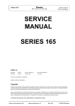
Weighing cell – Wägezelle
1.5.1
Overall view – Übersicht
11
320 BB
Components – Bestandteile
Pos. Pcs. Article number
Article
Artikel
1
2
3
4
5
6
7
8
9
10
11
12
13
14
15
16
17
18
19
20
1
1
1
1
2
2
1
8
1
1
1
1
1
2
1
1
1
1
1
1
1
N
N
see page 13
320-7006
320-2004
see page 13
N
see page 13
320-7130
360-5003
360-7005
part of (10)
part of (10)
300-7024
320-3080
360-2001
N
320-2032
240-4048
N
N
Chassis
Balance arm
Coupling
Coil cpl.
Flexure holder
Vertical flexure
Support piece
Horizontal flexure
Inner cone round chromed, A
Inner cone square, M/C/D
Floating sensor cpl.
Connection board
Temperature sensor board
Connection wire
Draft cover, A only
Cover support
Magnet cover
Transport safety device
Symmetry screw
Reference weight bearing left
Reference weight bearing right
Chassis
Waagbalken
Zugband
Spule kpl.
Lenker
Hängelager
Träger
Biegelager
Innenkonus rund verchromt, A
Innenkonus 4-kant, M/C/D
Lichtschranke kpl.
Verbindungsprint
Temperaturfühlerprint
Bronceband
Luftzugsdeckel, nur A
Deckelträger, nur A
Magnetdeckel
Transportsicherung
Symmetrieschraube
Referenzgewichtslager links
Referenzgewichtslager rechts
21
22
23
24
25
26
27
28
29
30
31
32
33
34
35
36
3
2
2
11
3
8
6
2
3
3
2
25
2
6
22
3
PN 1100-060
PN 1100-023
PN 1100-040
PN 1100-169
PN 1100-170
PN 1100-171
PN 1100-172
PN 1100-173
PN 1100-286
PN 1300-008
PN 1500-062
PN 1500-075
PN 1500-097
320-3013
320-3055
320-3018
Screw cyl. Phillips M3x4
Screw cyl. Phillips M3x6
Screw cyl. slot M3x8
Screw cyl. Torx M4x6
Screw cyl. Torx M4x8
Screw cyl. Torx M4x10
Screw cyl. Torx M4x12
Screw cyl. Torx M4x16
Grub screw M4x5
Nut hex-flanged M4
Washer M3
Spring washer M4
Washer brass M4
Base round
Base XR
Distance bolt
ZK-Schraube M3x4
ZK-Schraube M3x6
ZS-Schraube M3x8
ZT-Schraube M4x6
ZT-Schraube M4x8
ZT-Schraube M4x10
ZT-Schraube M4x12
ZT-Schraube M4x16
Gewindestift M4x5
Mutter 6-kant M4
Unterlagsscheibe M3
Spannscheibe M4
Unterlagsscheibe Messing M4
Beilage rund
Beilage XR
Distanzbolzen
12
320 BB
1.5.2
Components – Bestandteile
Flexure repair sets – Lager-Reparatursets
A repair set consists of the required spare flexures for one balance, i.e. 1 coupling, 2 vertical
flexures and 8 horizontal flexures.
Ein Reparaturset beinhaltet die benötigten Ersatzlager für eine Waage, also 1 Zugband, 2
Hängelager und 8 Biegelager.
3
6
Pos.
Article number
Article
3+6+8
350-8593
350-8592
350-8594
350-8595
Flexure
Flexure
Flexure
Flexure
1.5.3
8
Artikel
repair
repair
repair
repair
set,
set,
set,
set,
A
M
C
D
Lager-Reparaturset,
Lager-Reparaturset,
Lager-Reparaturset,
Lager-Reparaturset,
A
M
C
D
Particular spare flexures – Jeweilige Ersatz-Lager
Pos.
Article number
Article
Artikel
3
350-8539
350-8540
350-8541
Couplings, 5 pcs, A
Couplings, 5 pcs, M
Couplings, 5 pcs, C/D
Zugbänder, Set zu 5 Stk, A
Zugbänder, Set zu 5 Stk, M
Zugbänder, Set zu 5 Stk, C/D
6
350-8542
350-8543
350-8544
Vertical flexures, 10 pcs, A
Vertical flexures, 10 pcs, M/C
Vertical flexures, 10 pcs, D
Hängelager, Set zu 10 Stk, A
Hängelager, Set zu 10 Stk, M/C
Hängelager, Set zu 10 Stk, D
8
350-8545
350-8546
350-8547
350-8548
Horizontal
Horizontal
Horizontal
Horizontal
Biegelager,
Biegelager,
Biegelager,
Biegelager,
flexures,
flexures,
flexures,
flexures,
20
20
20
20
pcs,
pcs,
pcs,
pcs,
A
M
C
D
Set
Set
Set
Set
zu
zu
zu
zu
20
20
20
20
Stk,
Stk,
Stk,
Stk,
A
M
C
D
13
320 BB
1.6
Components – Bestandteile
Weighing pan D80 Group A2 – Waagschale D80 Gruppe A2
Pos. Pcs. Article number
Article
Artikel
-
Weighing pan, for windsh. XT
Weighing pan, for windsh. XB
Waagschale kpl., für Windschutz XT
Waagschale kpl., für Windschutz XB
1
1
1.7
320-8040
320-8041
Weighing pan 135, Group M – Waagschale 135, Gruppe M
Pos. Pcs. Article number
Article
Artikel
1
2
3
2
2
1
300-4059
300-4060
320-7014
Centring disk
Adhesive for centring disk
Weighing pan 135
Zentrierteller
Kleber für Zentrierteller
Waagschale 135
4
8
4
1
320-4047
350-7402
Centring bolt
Adapter, for windshield XB
Zentrierzapfen
Adapter, für Windschutz XB
-
1
1
320-8008
320-8007
Pan holder cpl., M1
Pan holder cpl., M2
Schalenträger kpl., M1
Schalenträger kpl., M2
14
320 BB
1.8
Components – Bestandteile
Weighing pan 170, Group C – Waagschale 170, Gruppe C
Pos. Pcs. Article number
Article
Artikel
1
2
3
2
2
1
300-4059
300-4060
320-7013
Centring disk
Adhesive for centring disk
Weighing pan 170
Zentrierteller
Kleber für Zentrierteller
Waagschale 170
4
8
4
1
320-4047
350-7402
Centring bolt
Adapter, for windshield XB
Zentrierzapfen
Adapter, für Windschutz XB
5
1
1
1
320-8006
320-8005
320-8004
Pan holder cpl., C1
Pan holder cpl., C2
Pan holder cpl., C3
Schalenträger kpl., C1
Schalenträger kpl., C2
Schalenträger kpl., C3
15
320 BB
1.9
Components – Bestandteile
Weighing pan 200, Group D – Waagschale 200, Gruppe D
Pos. Pcs. Article number
Article
Artikel
1
2
6
2
2
1
300-4059
300-4060
320-7012
Centring disk
Adhesive for centring disk
Weighing pan 200
Zentrierteller
Kleber für Zentrierteller
Waagschale 200
5
4
320-4047
Centring bolt
Zentrierzapfen
320-7003
Pan holder cpl., D
Schalenträger kpl., D
3+5
16
320 BB
1.10
Components – Bestandteile
Draftshield, XT – Windschutz, XT
17
320 BB
Components – Bestandteile
Pos. Pcs. Article number
Article
Artikel
1
2
3
4
5
6
7
8
9
10
11
12
13
14
15
16
17
18
19
20
21
22
23
24
25
26
27
28
290-2035
290-4050
320-4004
320-4008
320-4012
320-4015
320-4016
320-4017
320-4018
320-4019
320-4020
320-4044
320-7010
320-7028
320-7030
320-7031
320-7046
320-7047
320-7048
320-7058
320-7066
PN 1100-033
PN 1100-054
PN 1100-143
PN 1100-170
PN 1100-187
PN 1100-189
PN 1300-038
Protective ring
Guide
Cover
Top panel
Front glass
Guide rail right
Guide rail left
Sliding ring
Handle to lever
Sliding Block
Handle
Panel fastener
Side slide right cpl.
Side slide left cpl.
Lever left cpl.
Lever right cpl.
Back panel inside
Back panel outside
Top slide cpl.
Bottom plate cpl., XT
Bottom plate
Screw countersunk Phillips M3x5
Locking scr. cyl. Phillips KA30x8
Screw cyl. countersunk M4x12
Screw cyl. Torx M4x8
Screw counters. Phillips M4x12
Screw Eco-Fix Phillips M3x5
Nut square-flanged M4
Schutzring
Führung
Abdeckung
Deckel
Frontscheibe
Gleitschiene rechts
Gleitschiene links
Gleitring
Griff zu Hebel
Gleitstück
Griff
Glashalter
Seitenglas rechts kpl.
Seitenglas links kpl.
Hebel links kpl.
Hebel rechts kpl.
Rückwand innen
Rückwand aussen
Gläser oben kpl.
Bodenblech kpl., XT
Bodenplatte
SK-Schraube M3x5
ZK-Schraube KA30x8
ZS-Schraube M4x12
ZT-Schraube M4x8
SK-Schraube M4x12
EK-Schraube M3x5
Mutter 4-kant M4
350-8517
Draft shield, XT
Windschutz XT
-
1
1
1
1
1
1
1
1
2
2
2
2
1
1
1
1
1
1
1
1
1
2
2
2
4
2
2
2
18
320 BB
1.11
Components – Bestandteile
Draftshield 180, XB – Windschutz 180, XB
19
320 BB
Components – Bestandteile
Pos. Pcs. Article number
Article
Artikel
1
2
3
4
5
6
8
9
10
11
12
13
14
15
16
17
18
19
20
21
22
23
24
25
26
290-2035
320-2049
320-4028
320-4029
320-4031
320-4033
320-4036
320-4037
320-4042
320-4043
320-7022
320-7026
320-7051
320-7052
320-7059
320-7065
320-7098
320-7099
350-7402
PN 1046-001
PN 1100-078
PN 1100-103
PN 1100-183
PN 1100-184
PN 1100-185
Protective ring
Washer
Guide rail right
Guide rail left
Cover
Front glass
Handle
Nut
Slider
Cap
Profile
Bottom plate low
Side slide left low cpl.
Side slide right low cpl.
Top slide cpl.
Spring cpl.
Guide rail left cpl.
Guide rail right cpl.
Adapter, M
O-Ring
Screw cyl. Inbus M3x5
Screw cyl. slot M4x6
Locking scr. cyl. Phillips KA35x8
Screw cyl. Phillips M4x10
Locking scr. cyl. Phillips KA35x10
Schutzring
Unterlagsscheibe
Gleitschiene rechts
Gleitschiene links
Abdeckung
Frontscheibe
Griff
Befestigungsmutter
Gleiter
Abdeckkappe
Profil
Bodenplatte niedrig
Seitenglas links niedrig kpl.
Seitenglas rechts niedrig kpl.
Glas oben kpl.
Einstellfeder kpl.
Gleitschiene links kpl.
Gleitschiene rechts kpl.
Adapter, M
O-Ring
ZI-Schraube M3x5
ZS-Schraube M4x6
ZK-Schraube KA35x8
ZK-Schraube M4x10
ZK-Schraube KA35x10
350-8518
Draft shield 180, XB
Windschutz 180, XB
-
1
1
2
2
3
1
3
4
2
4
2
1
1
1
1
2
1
1
1
2
2
2
2
4
2
20
320 BB
1.12
Components – Bestandteile
Draftshield 260, XB – Windschutz 260, XB
21
320 BB
Components – Bestandteile
Pos. Pcs. Article number
Article
Artikel
1
2
3
4
5
6
7
8
9
10
11
12
13
14
15
16
17
18
19
20
21
22
23
24
290-2035
320-2049
320-4028
320-4029
320-4031
320-4036
320-4037
320-4039
320-4043
320-7023
320-7027
320-7053
320-7054
320-7059
320-7098
320-7099
320-7148
350-7402
PN 1046-009
PN 1100-078
PN 1100-103
PN 1100-183
PN 1100-184
PN 1100-293
Protective ring
Washer
Guide rail right
Guide rail left
Cover
Handle
Nut
Front glass
Cap
Profile
Bottom plate high
Side slide left high cpl.
Side slide right high cpl.
Top slide cpl.
Guide rail left cpl.
Guide rail right cpl.
Slider cpl.
Adapter, M
O-Ring
Screw cyl. Inbus M3x5
Screw cyl. slot M4x6
Locking scr. cyl. Phillips KA35x8
Screw cyl. Phillips M4x10
Screw cyl. Phillips M4x12
Schutzring
Unterlagsscheibe
Gleitschiene rechts
Gleitschiene links
Abdeckung
Griff
Befestigungsmutter
Frontscheibe
Abdeckkappe
Profil
Bodenplatte hoch
Seitenglas links hoch kpl.
Seitenglas rechts hoch kpl.
Glas oben kpl.
Gleitschiene links kpl.
Gleitschiene rechts kpl.
Gleiter kpl.
Adapter, M
O-Ring
ZI-Schraube M3x5
ZS-Schraube M4x6
ZK-Schraube KA35x8
ZK-Schraube M4x10
ZK-Schraube M4x12
350-8519
Draft shield 260, XB
Windschutz 260, XB
-
1
1
2
2
3
3
4
1
4
2
1
1
1
1
1
1
2
1
2
2
2
2
2
4
22
320 BB
1.13
Components – Bestandteile
Draftshield easy – Windschutz einfach
Pos. Pcs. Article number
Article
Artikel
1
2
4
5
Front frame cpl., 1 pc
Side frame cpl., 1 pc
Cover
Screw cyl. Phillips M3x8
Rahmen stirnseitig kpl., 1 Stk
Rahmen seitlich kpl. 1 Stk
Deckel
ZK-Schraube M3x8
1+2+4+5 320-8504
Draftshield easy
Windschutz einfach
3
6
Protective ring, M/C
Screw cyl. slot M4x8
Schutzring, M/C
ZS-Schraube M4x8
2
2
1
8
1
2
320-7007
320-7008
320-2014
PN 1100-024
320-4045
PN 1100-104
23
320 BB
1.14
Components – Bestandteile
Draft deflector M – Windabweiser M
Pos. Pcs. Article number
Article
Artikel
2
1
320-4089
Draft reflector, M
Windabweiser, M
1
3
1
2
320-4045
PN 1100-104
Protective ring, M/C
Screw cyl. slot M4x8
Schutzring, M/C
ZS-Schraube M4x8
24
320 BB
1.15
Components – Bestandteile
Twin Reference Weight Device – Zwillings-Referenzgewichts-Modul
Pos. Pcs. Article number
Article
Artikel
1
2
3
320-7139
320-2075
320-3087
320-3088
320-3089
PN 1100-017
PN 1100-295
Servo motor cpl.
Counterholder
Int. ref. weight, A
Int. ref. weight, M1/C1
Int. ref. weight, M2/C2/C3/D
Screw cyl. Phillips M3x10
Screw cap Inbus M4x6
Servomotor kpl.
Gegenlager
Int. Referenzgewicht, A
Int. Referenzgewicht, M1/C1
Int. Referenzgewicht, M2/C2/C3/D
ZK-Schraube M3x10
LI-Schraube M4x6
320-7140
Twin reference weight device cpl.
Zwillings-Referenzgewichts-Modul kpl.
4
5
1 .. 5
1
2
2
2
2
4
4
25
320 BB
1.16
Components – Bestandteile
Main board – Hauptprint
Pos. Pcs. Article number
Article
Artikel
-
Main board
Hauptprint
1
1.17
335-7220-020
Connector board – Steckerprint
Pos. Pcs. Article number
Article
Artikel
-
Connector board
Steckerprint
1
335-7201-010
26
320 BB
1.18
Components – Bestandteile
Display board VFD – Anzeigeprint VFD
Pos. Pcs. Article number
Article
Artikel
-
Display board VFD
Green display filter w. protect. foil
Anzeigeprint VFD
Grünes Anzeigefilter m. Schutzfolie
1
1
335-7205-010
320-4009
27
320 BB
1.19
Components – Bestandteile
Universal switching power adapter – Universal-Schaltnetzteil
Pos. Pcs. Article number
Article
Artikel
-
Universal switching power adapter
Universal-Schaltnetzteil
1
1.20
350-8384
Universal switching power adapter IP65 – Universal-Schaltnetzteil IP65
Pos. Pcs. Article number
Article
Artikel
-
Universal sw. pwr. adapter IP65
Universal-Schaltnetzteil IP65
1
350-8025
28
320 BB
Repairs
2
Repairs
2.1
Before you get started
2.1.1
Proceeding
•
Important: In case of a broken flexure, all flexures must be replaced.
•
It's safest to put all parts in their pristine place when re-assembling, particularely the screws!
•
Enough space and a sorted way of working are best conditions.
2.1.2
About these instructions
•
Numbers in round brackets refer to components shown in the overall view of chapter "1.5.1
Overall view – Übersicht" on page 11. Have a printout of this overwiev always at disposal!
•
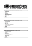
Numbers in square brackets refer to tools shown in chapter "2.1.3.1. Tool kit 350-8537" on
page 30. Have a printout of this chapter always at disposal, too!
29
320 BB
2.1.3
Repairs
Required tools
2.1.3.1 Tool kit 350-8537
4
1
5
6
2
3
7
8
14
9
10
11
12
13
Pos. Pcs. Article number
Article
1
2
3
4
5
6
7
8
9
10
11
12
13
14
15
16
17
Mounting plate
Support post long
Support post short
Screwdriver Torx M4
Screwdriver small No.1
Pin for flexure holders
Assembly jig with slot
Assembly jig with hole
Assembly pin for assembly jig
Centring spigot for flexures
Centring spigot for coil, 360/321
Centring spigot for coil, 320/330
Coupling anchor
Screw cyl. Torx M4x12
Alignment jig
Connecting cable
Centring bush
1
2
2
1
1
2
1
1
4
2
1
1
1
2
1
1
1
W 41-1688
W 41-1688-5
W 41-1688-6
350-6203
240-7124
PW 29.43.300
W 41-1700
W 41-1701
W 41-1677
W 41-1691
W 41-1774
W 41-1675
W 41-1674
PN 1100-172
W 41-1699
W 41-1578-8
W 41-1681
15
16
17
30
320 BB
Repairs
2.1.3.2 Instruments
•
Soldering iron
•
Voltmeter
2.1.3.3 Standard tools:
•
Box spanner Nos.4, 5.5 and 7
•
Flat-bladed screwdriver Nos.1, 2 and 4
•
Phillips screwdriver No.2
•
Hexagon socket wrenches SW 1.5mm, SW 2.5mm
•
Tweezers
•
Lens
2.1.4
Prepairing the tools
•
Screw the 2 long [2] and 2 short [3] support posts on the assembly plate as shown in the figure
of chapter "2.1.3.1 Tool kit 350-8537" on page 30.
•
Preheat the soldering iron to 310 +/- 5°C (590 +/- 10°F).
2.1.5
•
Spare parts
Have all required spare parts at disposal, the fitting flexures (3), (6) and (8), according to the
instructions in chapter "1.5.2 Flexure repair sets – Lager-Reparatursets" on page 13.
31
320 BB
Repairs
2.2
Opening the balance
2.2.1
Opening the balance
1.
Disconnect the balance from the mains (unplug the power adapter).
2.
Remove the windshield, the protective ring, the weighing pan and the pan holder.
3.
Unscrew the 3 screws on the balance's top using a No. 4 screwdriver (2 screws cyl. Phillips
M4x25 above the display and 1 screw cyl. slot M4x12 nearby the bubble level).
4.
Slightly raise the housing's top.
5.
Disconnect the membrane keypad ribbon cable from the main board.
2.2.2
Opening the IP65 balance
3 Screws IP65
Clamping ring
2 Screws cyl.
countersunk M4x14
1.
Disconnect the balance from the mains (unplug the power adapter).
2.
Remove the windshield, the protective ring, the weighing pan and the pan holder.
3.
Unscrew the 3 screws IP56 with a No. 1 screwdriver and remove the clamping ring.
4.
Unscrew the 3 screws on the balance's top (2 screws cyl. Phillips M4x25 above the display and 1
screw cyl. slot M4x12 nearby the bubble level) and the 2 screws cyl. countersunk M4x12 on the
balance's bottom using a No. 4 screwdriver.
5.
Slightly raise the housing's top. Take care of the sealing!
6.
Disconnect the membrane keypad ribbon cable from the main board.
32
320 BB
2.3
1.
Repairs
Removing the weighing cell from the housing‘s bottom
SCS only: Remove the 2 screws of the left counterholder and remove it with the reference
weight.
2.
Do so with the right part of the reference weight module, too.
3.
Unplug the floating sensor (10) from the main board using a small screwdriver.
4.
Turn over the housing‘s bottom and unscrew the 3 nuts (30) on the underside of the balance's
bottom.
5.
Hold the weighing cell only on the chassis and lift it out of the housing's bottom.
6.
The chassis can now be placed on the assembly plate for easier handling.
7.
To protect the weighing cell, fix both assembly jigs [7] and [8] with the 4 assembly pins [9].
33
320 BB
Repairs
2.4
Dismantling the weighing cell
2.4.1
Removing the coupling
1.
Unscrew the 2 screws (28), remove the coupling (3), its round bases (34) and spring washers
(32) (Group A: only the XR-bases (35)). Do not separate the screw components!
2.
Screw the coupling anchor [13] tightly on with its 2 screws [14] in place of the coupling.
2.4.2
Removing the 2 flexure holders
1.
Fix the upper flexure holder (5) into the chassis, using the 2 pins for flexure holders [6].
2.
Unscrew the 4 screws (26) of the flexure holder and remove them together with its 4 spring
washers (32), 2 on the chassis, 2 on the support piece (Group A: with its 4 XR-bases (35)).
3.
Remove the flexure holder together with the flexures which are still fixed on it, then remove the
pins from the holder.
4.
Do so with the lower flexure holder, too.
2.4.3
Removing the coil
1.
Unsolder the 2 connecting wires (13) carefully from the connection board (11) using the
tweezers.
2.
Unscrew the 3 screws (25) from the magnet cover (16). Remove the cover together with the
transport safety device (17) and the spring washer (32).
3.
Unscrew the 2 brass screws (23) from the coil (4) on the balance arm (2) using a No.2
screwdriver. Remove the coil carefully from the magnet pot, together with the washers (31).
2.4.4
Removing the support piece
1.
Unscrew the 3 grub screws (29) of the inner cone (9) and remove it.
2.
SCS only: Remove the left (19) and the right (20) reference weight bearing.
3.
Unscrew the upper screw (balance arm side) of the coupling anchor [13] and pull off the support
piece together with the coupling anchor over the assembly pins [9].
4.
Untighten the lower screw of the coupling anchor for roughly 2 turns. The support piece and the
coupling anchor are loosely held together now.
34
320 BB
2.4.5
Repairs
Removing the balance arm
1.
Unscrew the brass screw from the stopper, turn it inwards ca. 90° and gently re-tighten the
brass screw.
2.
Unscrew the 4 screws (28) from the vertical flexures (6) and remove them together with its
round bases (36) and spring washers (32).
Note: Since the lug of the floating sensor is firmly attached to the balance arm, the floating sensor
must be unscrewed to dismantle the balance arm and gently tilted to the rear:
3.
Unscrew the screw (21) from the connection board (11).
4.
Unscrew the 3 screws (24) of the floating sensor and gently tilt the floating sensor to the rear.
5.
Remove the two inner assembly pins [9], i.e. unscrew them from the balance arm.
6.
Remove the two outer assembly pins [9], i.e. unscrew them from the chassis.
7.
Remove the two assembly jigs [7] and [8].
8.
Carefully tilt the balance arm over the pot and the floating sensor and take it out.
35
320 BB
Repairs
2.5
Exchanging the horizontal flexures
2.5.1
Removing the old horizontal flexures
1.
Release all screws from the flexure holders and remove the old flexures together with their
spring washers.
2.5.2
Installing new horizontal flexures
Mark
platesided!
1.
Place a flexure holder on the assembly plate [1]. The mark has to be upside-down, i.e. assembly
plate sided!
2.
Place 4 new horizontal flexures (8) carefully on the assembly plate, observe the alignment of
their cut edges!
3.
Place the 4 spring washers (32) (Group A: 4 XR-bases (35)) on the flexures and fix them tightly
to the holder with their screws (24).
4.
Take the complete flexure holder carefully off the assembly plate. Do not touch the flexures!
5.
Prepare the other flexure holder the same way.
36
320 BB
Repairs
2.6
Cleaning
2.6.1
Cleaning the magnet pot
1.
Wrap a double-sided adhesive tape around a flat stick.
2.
Dab with the stick on the ground of the pot.
3.
Prepare a thin and round stick the same way and spin it through the gap between the pot‘s wall
and the magnet.
4.
Dab over the top of the magnet pot with a piece of adhesive tape.
2.6.2
1.
Using a lint-free cloth, remove any contamination from the coil.
with adhesive tape; risk of injury!
2.6.3
1.
Cleaning the coil
Caution: Do not clean the coil
Checking the cleanliness again
Inspect the annular gap and the coil for residual contamination and clean if necessary.
37
320 BB
Repairs
2.7
Assembling the weighing cell
2.7.1
Assembling the balance arm
1.
Place the assembly jigs [7] + [8] with 2 assembly pins [9] on the chassis, position them
horizontally using the alignment jig [15] and tighten the two assembly pins [9] with a No. 4 box
spanner.
2.
Carefully introduce the balance arm (2) over the magnet pot and pass it to the floating sensor.
3.
Assemble the balance arm with 2 assembly pins [9] loosely behind the assembly jigs. The
balance arm must remain moveable.
4.
Firmly tighten first the one, then the other inner assembly pin [9] of the assembly jigs [7] and
[8].
2.7.2
Assembling the coil, the magnet cover and the transport safety device
1.
Place the coil onto the balance arm, centre it with the centring spigot [11] and fix it firmly with
2 brass screws (23) and 2 washers (31). The centring spigot must be smoothly removable!
2.
Slightly pre-fix the magnet cover (16) with its left and right screw (25).
3.
Gently pre-assemble the transport safety device (17) with the third screw (25) and spring
washer (32).
4.
The centring bush [17] shall be introduced between the balance arm-pilot and the transport
safety device to assure a constant annular gap. Tighten the screw (25), remove the centring
bush and tighten the other two pre-fixed magnet cover screws.
38
320 BB
2.7.3
Repairs
Assembling the floating sensor and the stopper
1.
Press the floating sensor carefully into the cutout of the chassis in the direction of the pot and
fix it to the chassis with 3 screws (24).
2.
Fix the connection board (11) onto the chassis with the screw (21).
3.
Solder the two connection wires (1) parallelly and strain-freely to the connection board.
4.
Turn back the stopper by 90° and tighten it with its brass screw.
5.
The stopper has to be free of play and lie centrally in the symmetry screw (18). If necessary,
adjust the symmetry screw.
39
320 BB
2.7.4
Repairs
Assembling new vertical flexures
1.
To facilitate the assembly, the chassis can be placed on the assembly plate. Take care of the
floating sensor!
2.
Bring a new flexure (6) into position, its slot has to be on the balance arm side (bottom).
3.
Centre the flexure with a centring spigot [10] first on the chassis side (top), then on the balance
arm side (bottom).
4.
Tighten the first (upper) centring spigot, then remove the second (lower) centring spigot. Do
not touch the flexure and fix it there with its round base (34) and spring washer (32) (Group A:
with its XR-base (35) only) and its screw (27).
5.
Remove the remained (upper) centring spigot and fix the flexure the same way on the chassis
side.
6.
Do so with the other flexure, too.
40
320 BB
2.7.5
Repairs
Assembling the support piece and the inner cone
1.
Introduce the support piece with the loosely held coupling anchor over the two inner assembly
pins [9]. It must be possible to push the support piece smoothly over the two inner assembly
pins. If not, release and tighten them again.
2.
Screw the support piece and the balance arm together using the coupling anchor [13] and its
two screws [14].
3.
Assemble the inner cone (12) with the 3 grub screws (29) to the support piece.
4.
SCS only: Re-assemble the two reference weight bearings (19) and (20) with the 2 screws (27)
and spring washers (32/Group A: 35).
41
320 BB
2.7.6
Repairs
Assembling the flexure holders
1.
Introduce the two pins for flexure holders [6] in the first pre-assembled holder the way that the
shoulder of the pins is opposite the screw heads on the holder.
2.
Bring the two pins with the holder into position in the chassis.
3.
Lower the holder carefully over the two pins on the chassis, until the flexures just touch the
chassis and the support piece.
4.
Fix the holder with its 4 spring washers (32) (Group A: with its 4 XR-bases (35)) and screws
(26).
5.
Push the two pins through, up to the installed horizontal flexures holder.
6.
Introduce and fix on the opposite side the other pre-assembled flexure holder the same way.
7.
Gently pull the two pins out of the flexure holders. They must be smoothly removeable!
42
320 BB
2.7.7
Repairs
Assembling a new coupling
1.
Remove the coupling anchor [13].
2.
Bring the new coupling into position, its slot has to be on the support piece side.
3.
Centre the coupling first on the balance arm side, then on the support piece side, using a
centring spigot [10].
4.
Tighten the first (upper) centring spigot, then carefully remove the second (lower) centring
spigot. Do not touch the coupling and fasten it on the support piece side with its round base
(34) and spring washer (32) (Group A: with its XR-base (35) only) and screw (28).
5.
Remove the second (upper) centring spigot and fasten the coupling on the balance arm side the
same way.
2.7.8
Dismantling the assembly jigs
1.
Remove the 2 inner assembly pins [9] carefully.
2.
Remove the 2 outer assembly pins [9] carefully.
3.
Take out the two assembly jigs [7] and [8] by sliding them sidewards.
4.
Remove the two assembly pins for flexure holders [6] carefully.
43
320 BB
2.8
Repairs
Installing the weighing cell into the housing‘s bottom
1.
Carry out a further movement check with the lens on the balance arm. The balance arm must
not touch the transport safety device (17)!
2.
Place the weighing cell carefully into the housing‘s bottom. Ηold the cell only on its chassis!
3.
Tilt the housing‘s bottom to the side and fix the weighing cell from below with the 3 nuts (30).
4.
Connect the floating sensor (10) to the main board.
5.
SCS only: Insert the internal reference weights and mount the counterholders. The
counterholders have to rest fully on the reference weights, impeding them to move.
44
320 BB
Adjustments
3
Adjustments
3.1
Before you get started
3.1.1
Table of specifications
In carrying out the following adjustments, it is necessary to know the specifications of the balance in
service. You may download the specifications for servicing from our website:
http://www.precisa.com
The following instructions refer often to that specifications, have a printout of them always at
disposal!
3.1.2
Placing loads
Place all loads always carefully and, unless otherwise asked, in the center of the weighing pan!
3.2
Setting the balance to the factory mode (the balance is open)
Pin header
for jumper J1
1.
Remove the jumper J1 from the main board.
2.
Level the balance with the levelling screws and connect it to the mains with the power adapter.
The balance starts up in the factory mode.
45
320 BB
3.3
Adjustments
Adjusting the symmetry
Symmetry
screw
Symmetry
pin header
S3
1.
Ensure the balance is levelled and set to the factory mode, see chapter "3.2 Setting the balance
to the factory mode (the balance is open)" on page 45.
2.
Connect the connecting cable [16] to the symmetry pin header S3.
3.
Connect the voltmeter to the connecting cable.
4.
The voltmeter must show approximately the same voltage in both end positions of the balance
arm (once positive, once negative), if it doesn't, adjust the position of the balance arm with the
symmetry screw.
5.
Detach the connecting cable with the voltmeter from the balance.
3.4
Checking the pre-load
1.
Ensure the balance is levelled and set to the factory mode, see chapter "3.2 Setting the balance
to the factory mode (the balance is open)" on page 45.
2.
The pre-load error 60 (below minimal converter range) must not appear with placed weighing
pan without load.
3.
The pre-load error 61 (above maximal converter range) must not appear with placed weighing
pan with full load.
4.
If such an error is displayed, re-adjust the symmetry and ensure the balance arm does move
freely. It must not touch the transport safety device!
46
320 BB
Adjustments
3.5
Adjusting the corner load
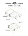
3.5.1
Determining the corner load values
Pin header S4
for keypad
1.
Ensure the balance is levelled and set to the factory mode, see chapter "3.2 Setting the balance
to the factory mode (the balance is open)" on page 45.
2.
Place the upper part of the housing on the right alongside the lower part of the housing and
connect the membrane keypad to the pin header S4.
3.
Put the pan holder and the weighing pan on the balance.
4.
Have, according to the specifications, a suitable corner load reference weight at disposal.
D
C
Z
A
B
5.
Place the weight on Z and tare the balance.
6.
Place the weight on A, B, C and D. Every single value has to stay, according to the
specifications, within the tolerated range!
47
320 BB
3.5.2
Adjustments
Adjusting the corner load (Group M/C/D)
Note: Skip this chapter if the determined corner load values stay within the tolerated range.
1
2
A-C
B-D
•
The difference of the diagonal A-C is adjusted with the left corner load screw 1.
•
The difference of the diagonal B-D is adjusted with the right corner load screw 2.
•
Turning the corner load screw clockwise
slides the difference of the diagonal in negative
direction. The displayed value relatively decreases.
•
Turning the corner load screw counterclockwise
slides the difference of the diagonal in
positive direction. The displayed value relatively increases.
Procedure
1.
Ensure the balance is levelled and set to the factory mode, see chapter "3.2 Setting the balance
to the factory mode (the balance is open)" on page 45.
C = tared = 0
C
D = tared = 0
D
A
B
2.
Place the weight on C, tare the balance, shift the weight to A and calculate the difference:
∆AC = A-C = A-0 = A [d]; (C = tared = 0); Example: ∆AC = A = +12d.
3.
Place the weight on D, tare the balance, shift the weight to B and calculate the difference:
∆BD = B-D = B-0 = B [d]; (D = tared = 0); Example: ∆BD = B = -7d.
Important: Start adjusting the diagonal with the larger difference!
4.
The difference of the diagonal A-C is larger and positive (+12d). Turning the corner load screw 1
clockwise
slides the difference in negative direction (+12 .. +11 .. +10 ..).
5.
The difference of the diagonal B-D is smaller and negative (-7d). Turning the corner load screw
2 counterclockwise slides the difference in positive direction (-7 .. -6 .. -5 ..).
6.
Keep determining the diagonal differences as described in step 2 and 3 and reduce them, until
all 4 corner load deviations stay within the tolerated range, see previous chapter "3.5.1
Determining the corner load values" from step 4 on.
48
320 BB
3.5.3
Adjustments
Adjusting the corner load (Group A)
Note: Skip this chapter if the determined corner load values stay within the tolerated range.
1
2
A-C
B-D
•
The difference of the diagonal A-C is adjusted with the left outer and inner corner load screw 1.
•
The difference of the diagonal B-D is adjusted with the right outer and inner corner load screw 2.
Outer
corner load screw
Inner
corner load screw
Rough adjustment: the outer corner load screws have the same turning sense as in group M/C/D
•
Turning the outer corner load screw clockwise
slides the difference of the diagonal roughly in
negative direction. The displayed value relatively decreases.
•
Turning the outer corner load screw counterclockwise
slides the difference of the diagonal
roughly in positive direction. The displayed value relatively increases.
Fine adjustment: Caution, the inner and outer corner load screws have contrary turning senses!
•
Turning the inner corner load screw counterclockwise
slides the difference of the diagonal
finely in negative direction. The displayed value relatively decreases.
•
Turning the inner corner load screw clockwise
slides the difference of the diagonal finely in
positive direction. The displayed value relatively increases.
49
320 BB
Adjustments
Procedure
1.
Ensure the balance is levelled and set to the factory mode, see chapter "3.2 Setting the balance
to the factory mode (the balance is open)" on page 45.
C = tared = 0
C
D = tared = 0
D
A
B
Rough adjustment having diagonal differences ≥ +/-35d:
2.
Place the weight on C, tare the balance, shift the weight to A and calculate the difference:
∆AC = A-C = A-0 = A [d]; (C = tared = 0); Example: ∆AC = A = +68d.
3.
Place the weight on D, tare the balance, shift the weight to B and calculate the difference:
∆BD = B-D = B-0 = B [d]; (D = tared = 0); Example: ∆BD = B = -57d.
4.
Release the holding grub screws of the outer corner load screws by means of a hexagon socket
wrench SW 1.5mm:
Important: Start adjusting the diagonal with the larger difference!
5.
The difference of the diagonal A-C is larger and positive (+68d). Turning the outer corner load
screw 1 clockwise
slides the difference in negative direction (+68 .. +67 .. +66 ..). Caution:
Co-turn the inner corner load screw, ensuring its thread keeps staying until its upper end into
the outer corner load screw!
50
320 BB
Adjustments
6.
The difference of the diagonal B-D is smaller and negative (-57d). Turning the outer corner load
screw 2 counterclockwise
slides the difference in positive direction (-57 .. -56 .. -55 ..).
Important: Co-turn the inner corner load screw, ensuring its thread keeps staying until its upper
end into the outer corner load screw!
7.
Keep determining and reducing the diagonal differences, until they fall below +/-35d.
8.
Fix the holding grub screws of the outer corner load screws by means of a hexagon socket
wrench SW 1.5mm again.
Fine adjustment having diagonal differences < +/-35d: Caution, the inner and outer corner load screws have
contrary turning senses!
9.
Place the weight on C, tare the balance, shift the weight to A and calculate the difference:
∆AC = A-C = A-0 = A [d]; (C = tared = 0); Example: ∆AC = A = +22d.
10. Place the weight on D, tare the balance, shift the weight to B and calculate the difference:
∆BD = B-D = B-0 = B [d]; (D = tared = 0); Example: ∆BD = B = -19d.
Important: Start adjusting the diagonal with the larger difference!
11. The difference of the diagonal A-C is larger ad positive (+22d). Turning the corner load screw 1
counterclockwise
slides the difference in negative direction (+22 .. +21 .. +20 ..).
12. The difference of the diagonal B-D is smaller and negative (-19d). Turning the corner load screw
2 clockwise
slides the difference in positive direction (-19 .. -18 .. -17 ..).
13. Keep determining the diagonal differences as described in step 9 and 10 and reduce them, until
all 4 corner load deviations stay within the tolerated range, see chapter "3.5.1 Determining the
corner load values" from step 4 on.
51
320 BB
3.6
1.
Adjustments
Checking the lowering process of the internal reference weights (SCS only)
Ensure the balance is levelled and set to the factory mode, see chapter "3.2 Setting the balance
to the factory mode (the balance is open)" on page 45.
Pin header S4
for keypad
2.
Place the upper part of the housing on the right alongside the lower part of the housing and
connect the membrane keypad to the pin header S4.
3.6.1
Checking the lowering process of the internal reference weights (10-Key version only)
F until "TESTPROG 1" appears.
1.
Hold
2.
Lower the weights with {DOWN} and lift them with {UP}.
3.
If the weights don't run cleanly into the weighing cell's bearings, re-align the reference weight
device.
3.6.2
Checking the lowering process of the internal reference weights (5-Key version only)
1.
Hold MODE until "TESTPROG 1" appears.
2.
Lower the weights with {DOWN} (Hold REF until "FKT-KEY 4" appears) and lift them with {UP}
(hold REF until "FKT-KEY 3" appears).
3.
If the weights don't run cleanly into the weighing cell's bearings, re-align the reference weight
device.
52
320 BB
3.7
Adjustments
Closing the balance
1.
Disconnect the balance from the mains (unplug the power adapter).
2.
Remove the weighing pan and the pan holder.
Pin header S4
for keypad
Pin header
for jumper J1
3.
Ensure the Jumper J1 is set and the membrane keypad is connected to the pin header S4.
4.
Ensure that both, the display and the glass of the housing's top are clean.
5.
Place the housing's top on its bottom and fasten together with the 3 screws (2 screws cyl.
Phillips M4x25 above the display and 1 screw cyl. slot M4x12 nearby the bubble level).
6.
IP65 only: Fix the housing with the 2 screws cyl. countersunk M4x14. Fix the membrane carefully
with the clamping ring and its 3 screws IP65 without causing any wrinkles on the membrane.
3 Screws IP65
Clamping ring
2 Screws cyl.
countersunk M4x14
7.
Put the pan holder, the weighing pan and, if present, the draftshield on the balance.
53
320 BB
3.8
Adjustments
Setting the balance to the service mode (the balance is closed)
Service switch
3.8.1
Setting the balance to the service mode (10-Key version only)
1.
Level the balance with the levelling screws and connect it to the mains with the power adapter.
2.
Press the service switch on the rear of the housing's bottom with the small screwdriver [5] ⇒
the display flashes once.
3.
Press
F ⇒ "CODE 0" appears.
4.
Press
E ⇒ "CODE 0000" appears.
5.
Enter the service access code 5236 with
in the service mode.
3.8.2
C, D and B
and confirm with
E . The balance is now
Setting the balance to the service mode (5-Key version only)
1.
Level the balance with the levelling screws and connect it to the mains with the power adapter.
2.
Press the service switch on the rear of the housing's bottom with the small screwdriver [5] ⇒
the display flashes once.
3.
Press MODE twice ⇒ "CODE 0000" appears.
4.
Pressing MODE changes the value of the figure, holding changes to the next figure.
5.
Enter the service access code 5236 and confirm with PRINT. The balance is now in the service
mode.
54
320 BB
3.9
Adjustments
Adjusting the linearity
Caution: Adjusting the linearity erases all S-correction factors, too. This chapter has therefore to be processed
entirely!
3.9.1
Adjusting the linearity (10-Key version only)
1.
Ensure the balance has reached its operating temperature, is levelled and set to the service
mode, see chapter "3.8 Setting the balance to the service mode (the balance is closed)" on page
54.
2.
Have, according to the specifications, suitable linearisation reference weights at disposal: 2x half
load, 1x quarter load.
3.
Hold
4.
Have the weighing pan empty and press {0} ⇒ the balance catches the zero point and the
display flashes.
5.
Wait until the flashing stops, place the half load and press {1/2} ⇒ the balance catches the half
load value and the display flashes.
6.
Wait until the flashing stops, place the full load and press {1/1} ⇒ the balance catches the full
load value and the display flashes.
7.
Wait until the flashing stops and press {SET} ⇒ the balance sets the linearisation factors and
displays the full weight value.
8.
Empty the weighing pan, tare and check whether at quarter load and three quarter load the
linearity stays within the tolerated range, too. If it doesn't, process chapter "3.11 Adjusting the
S-correction" on page 58.
9.
With SCS: Process chapter "3.12 Adjusting the internal reference weight (SCS only)" on page 59.
Without SCS: Switch the balance off an on (by pressing ON/OFF twice) ⇒ the balance quits the
F until "LINEARITY" appears.
service mode.
3.9.2
Adjusting the linearity (5-Key version only)
1.
Ensure the balance has reached its operating temperature, is levelled and set to the service
mode, see chapter "3.8 Setting the balance to the service mode (the balance is closed)" on page
54.
2.
Have, according to the specifications, suitable linearisation reference weights at disposal: 2x half
load, 1x quarter load.
3.
Hold MODE until "LINEARITY" appears.
4.
Have the weighing pan empty and press {0} (hold REF until "FKT-KEY 1" appears) ⇒ the
balance catches the zero point and the display flashes.
5.
Wait until the flashing stops, place the half load and press {1/2} (hold REF until "FKT-KEY 2"
appears) ⇒ the balance catches the half load value and the display flashes.
6.
Wait until the flashing stops, place the full load and press {1/1} (hold REF until "FKT-KEY 3"
appears) ⇒ the balance catches the full load value and the display flashes.
7.
Wait until the flashing stops and press {SET} (hold REF until "FKT-KEY 4" appears) ⇒ the
balance sets the linearisation factors and displays the full weight value.
8.
Empty the weighing pan, tare and check whether at quarter load and three quarter load the
linearity stays within the tolerated range. If it doesn't, process chapter 3.11 Adjusting the Scorrection" on page 58.
9.
With SCS: Process chapter "3.12 Adjusting the internal reference weight (SCS only)" on page 59.
Without SCS: Switch the balance off an on (by pressing ON/OFF twice) ⇒ the balance quits the
service mode.
55
320 BB
3.9.3
Adjustments
Checking the linearity
1.
Ensure the balance has reached its operating temperature, is levelled and in weighing mode
(switch it off an on by pressing ON/OFF twice).
2.
Have, according to the specifications, suitable linearisation reference weights at disposal: 2x half
load, 1x quarter load.
3.
Tare the balance and check whether the linearity stays at half, full, quarter and three quarter
load within the tolerated range. If it doesn't at half or full load, adjust the linearity again. If it
doesn't at quarter or three quarter load, process chapter "3.11 Adjusting the S-correction" on
page 58.
3.10
Checking the adjustments of the closed balance
3.10.1 Checking the repeatability (with SCS)
1.
Process chapter "3.12 Adjusting the internal reference weight (SCS only)" on page 59.
2.
Ensure the balance has reached its operating temperature, is levelled and in weighing mode
(switch it off an on by pressing ON/OFF twice).
3.
Have, according to the specifications, a suitable full load reference weight at disposal.
4.
Tare the balance and check whether the repeatability stays within the tolerated range. If it
doesn't, process firstly chapter "3.12 Adjusting the internal reference weight (SCS only)" on
page 59, then this chapter completely again.
3.10.2 Checking the repeatability (without SCS)
1.
Ensure the balance has reached its operating temperature, is levelled and in weighing mode
(switch it off an on by pressing ON/OFF twice).
2.
Have, according to the specifications, a suitable full load reference weight at disposal.
3.
Ensure by the configuration menu (see operating instructions) the calibration/adjustment mode
is set to "EXTERNAL".
4.
Adjust the balance manually with the ready full load weight by holding TARE until
"CALIBRATION"/"ADJUSTMENT" appears and following the displayed instructions, see also the
operating instructions.
5.
Tare the balance and check whether the repeatability stays within the tolerated range. If it
doesn't, re-adjust the balance (see previous step) and process this chapter completely again.
56
320 BB
Adjustments
3.10.3 Checking the corner load
1.
Ensure the balance has reached its operating temperature, is levelled and in weighing mode
(switch it off an on by pressing ON/OFF twice).
2.
Have, according to the specifications, a suitable corner load reference weight at disposal.
D
C
Z
A
B
3.
Place the weight on Z and tare the balance.
4.
Place the weight on A, B, C and D. Every single value has to stay, according to the
specifications, within the tolerated range! If they don't, re-adjust the corner load as described in
chapter "3.5.2 Adjusting the corner load (Group M/C/D)" on page 48 or "3.5.3 Adjusting the
corner load (Group A)" on page 49, close the balance and process this chapter completely again.
3.10.4 Checking the linearity
1.
Process chapter "3.9.3 Checking the linearity" on page 56.
57
320 BB
3.11
Adjustments
Adjusting the S-correction
Important: The S-correction only has to be adjusted in case the linearity at half and full load stays within and at
quarter and three quarter load stays out of the tolerated range:
Once the linearity is adjusted the balance response behaviour may follow an S-curve, i.e. the
linearity at quarter and three quarter load may stay out of the tolerated range and has to be
adjusted:
∆a
b (3/4 load)
a (1/4 load)
∆b
3.11.1 Measuring the S-curve
1.
Ensure the balance has reached its operating temperature and is in weighing mode (turn it off
and on by pressing ON/OFF twice).
2.
Have, according to the specifications, suitable linearisation reference weights at disposal: 1x half
load, 1x quarter load.
3.
Tare the balance, place the quarter load and note the displayed value.
4.
Place the three quarter load and note the displayed value.
5.
Calculate the differences:
∆a = (displayed quarter load) - (placed quarter load)
∆b = (displayed three quarter load) - (placed three quarter load)
Example:
∆a = 50.0004g - 50.0000g = 0.0004g
∆b = 149.9998g - 150.0000g = -0.0002g
3.11.2 Calculating the S-correction factors
1.
Indicate the differences in digits and change their signs:
Sa = -∆a [d]
Sb = -∆b [d]
Example:
∆a = 0.0004g = +4 d ⇒ Sa = -∆a = -4 d
∆b = -0.0002g = -2 d ⇒ Sb = -∆b = +2 d
3.11.3 Entering the S-correction factors (10-Key version only)
1.
Ensure the balance has reached its operating temperature, is levelled and set to the service
mode, see chapter "3.8 Setting the balance to the service mode (the balance is closed)" on page
54.
2.
Hold
3.
F until "SCORRECTION", followed by "SET SECTOR-A +0" appears.
Enter the S-correction factor Sa with C and D and set it with {SET} (press A).
4.
Switch to sector b with {SECTOR} (press B). "SET SECTOR-B +0" appears.
5.
Enter the S-correction factor Sb with
6.
Hold
7.
Process chapter "3.10 Checking the adjustments of the closed balance" on page 56.
C and D and set it with {SET} (press A).
F until "BALANCING" appears.
58
320 BB
Adjustments
3.11.4 Entering the S-correction factors (5-Key version only)
1.
Ensure the balance has reached its operating temperature, is levelled and set to the service
mode, see chapter "3.8 Setting the balance to the service mode (the balance is closed)" on page
54.
2.
Hold MODE until "SCORRECTION", followed by "SET SECTOR-A +0" appears.
3.
Enter the S-correction factor Sa
with {UP} (hold REF until "FKT-KEY 3" appears)
and {DOWN} (hold REF until "FKT-KEY 4" appears)
and set it with {SET} (hold REF until "FKT-KEY 1" appears).
4.
Switch to sector b with {SECTOR} (hold REF until "FKT-KEY 2" appears). "SET SECTOR-B +0"
appears.
5.
Enter the S-correction factor Sb
with {UP} (hold REF until "FKT-KEY 3" appears)
and {DOWN} (hold REF until "FKT-KEY 4" appears)
and set it with {SET} (hold REF until "FKT-KEY 1" appears).
6.
Hold MODE until "BALANCING" appears.
7.
Process chapter "3.10 Checking the adjustments of the closed balance" on page 56.
3.12
Adjusting the internal reference weight (SCS only)
Important: The internal reference weight has to bee adjusted, after the weighing cell has been repaired, or the
linearity or the S-correction has been adjusted!
It is possible to vary the full load reference weight within particular step sizes which may be,
according to your actual balance, 10, 50, 100 or 500g. This allows an adjustment either with various
reference weights at disposal or close to the usual operating range of the balance.
Important: Ensure the reference weight lays within the permitted range of +/- 0.3d of its nominal
value! Example: A 4200C of a customer, who usually weighs loads of 2.8 kg, asks for 2000g. Its
reference weight step size is 500g. A reference weight of 3000g (2000g + 2 steps of 500g) is the
closest to the usual operating range. Place such a reference weight if its mass lays within the range
of 2999.997g .. 3000.003g (maximum deviation = +/- 0.3d = +/- 0.003g at d=0.01g, see
specifications).
1.
Ensure the balance has reached its operating temperature, is levelled and set to the service
mode, see chapter "3.8 Setting the balance to the service mode (the balance is closed)" on page
54.
2.
Have, according to the specifications, a suitable full load reference weight at disposal.
3.
Hold TARE until "CALIBRATION"/"ADJUSTMENT" appears. The balance starts carrying out an
internal adjustment without setting the obtained correction factors, starts thereupon with the
external adjustment and asks, as soon as the zero point is measured, for the reference weight.
Its valuee is displayed flashing.
4.
Place the asked weight, or better, the one placed at disposal. Tthe balance catches its value and
the display flashes. As soon as the flashing stops, the balance asks for the zero point. This is
displayed flashing: "--0000 g".
5.
Remove the weight. The balance continues with the external adjustment, determines newly the
correction factors for the internal reference weight, carries out immediately an internal
adjustment and finally turns itself off and on, in order to quit the service mode.
59
320 BB
3.13
Adjustments
Error messages
3.13.1 Operating errors; Error disappears by correct use or application
Code Cause
Remedy
1
3
4
5
Invalid firmware
Load too small
Wrong anti theft code
7 times consecutively wrong anti theft code
8
9.0
9.1
9.2
9.3
30
Zero point out of range
Bad adjustment factor
Zero point deviation exceeded
Deviation of internal reference weight exceeded
Bad adjustment factor
No internal reference weight
31
No external reference weight
47
48
49
53
60
61
Too much values
Not the pristine unit
Too few values
Values out of the +/- 50% range
Value being below the converter range
Value exceeding the converter range
Load right firmware
Use higher load
Enter right code
Enter unlock code,
contact service
Repeat linearisation
Repeat adjustment
Repeat adjustment
Repeat adjustment
Repeat adjustment
Acknowledge with TARE
Adjust internal reference weight
Acknowledge with TARE
Adjust external reference weight
Record less values
Set to the pristine unit
Record more values
Place loads within the range
3.13.2 Fatal errors; Balance stays still, error remediable in service mode
Code Cause
Remedy
10
11
21
22
23
Repeat linearisation
Repeat adjustment
Contact service
Contact service
Contact service
No
No
No
No
No
linearity values
adjustment factors
SCS temperature compensation values
temperature compensation values
SCS temperature non-linearity compensation values
3.13.3 Hardware errors; Balance stays still
Code Cause
Remedy
14
16
17
18.1
Contact service
Exchange the µ-controller
Exchange the RAM
Load the right firmware
Exchange the flash memory
Load the right firmware
Exchange the flash memory
Exchange the µ-controller
Contact service
Check floating sensor connections
Compatibility conflict
Broken internal RAM
Broken external RAM
Wrong firmware checksum
18.2 No approved firmware in an approved balance
18.9 Wrong µ-controller firmware checksum
19
Compatibility conflict
20
Erroneous temperature measurement
60
320 BB
3.14
Adjustments
Discussion with the manufacturer
Important: Have at disposal the following information in discussions with the manufacturer:
•
Balance model: e.g. XT 220A
•
Order number: e.g. 320-9201 (label on the rear of the balance)
•
Serial number: e.g. 5001057 (label on the rear of the balance)
•
Firmware ID: e.g. E01-0000.P01 (appears on the display when plugging the balance to the
mains)
•
A precise description of the failure
•
Weighing results
Precisa Gravimetrics AG
Moosmattstrasse 32
Po-Box 352
CH-8953 Dietikon
Tel.
Fax
E-mail
+41 44 744 28 28
+41 44 744 28 38
[email protected]
61
320 BB
Reparatur
4
Reparatur
4.1
Bevor Sie beginnen
4.1.1
Vorgehen
•
Wichtig: Bei einem gebrochenen Lager müssen jeweils alle Lager ersetzt werden!
•
Jedes ausgebaute Teil wieder an seine ursprüngliche Stelle einzubauen, besonders die
Schrauben, ist am sichersten!
•
Ausreichend Platz und ein geordnetes Arbeiten sind beste Voraussetzungen.
4.1.2
Über diese Anleitung
•
Zahlen in runden Klammern beziehen sich auf Teilepositionen der Wägezellenübersicht, wie im
Kapitel "1.5.1 Overall view – Übersicht" auf Seite 11 angegeben. Diese Übersicht ausgedruckt
stets griffbereit halten!
•
Zahlen in eckigen Klammern beziehen sich auf Positionen des Werkzeugsatzes, wie im Kapitel
"4.1.3.1 Werkzeugsatz 350-853" auf seite 63 abgebildet. Auch diese Abbildung ausgedruckt
stets griffbereit halten!
62
320 BB
4.1.3
Reparatur
Benötigtes Werkzeug
4.1.3.1 Werkzeugsatz 350-8537
4
1
5
6
2
3
7
8
14
9
10
11
12
13
Pos. Anz. Artikelnummer
Artikel
1
2
3
4
5
6
7
8
9
10
11
12
13
14
15
16
17
Montageplatte
Auflagestift lang
Auflagestift kurz
Schraubenzieher Torx M4
Schraubenzieher klein Nr.1
Absteckstift zu Lenker
Montagelehre mit Langloch
Montagelehre mit Loch
Montagestift zu Montagelehre
Zentrierstift Lager
Zentrierstift für Spule, EP/ES
Zentrierstift für Spule, XT/XB
Zugbandanker
ZT-Schraube M4x12
Ausrichtlehre zu Montagelehre
Verbindungskabel
Zentrierbüchse
1
2
2
1
1
2
1
1
4
2
1
1
1
2
1
1
1
W 41-1688
W 41-1688-5
W 41-1688-6
350-6203
240-7124
PW 29.43.300
W 41-1700
W 41-1701
W 41-1677
W 41-1691
W 41-1774
W 41-1675
W 41-1674
PN 1100-172
W 41-1699
W 41-1578-8
W 41-1681
15
16
17
63
320 BB
Reparatur
4.1.3.2 Geräte:
•
Lötkolben
•
Voltmeter
4.1.3.3 Standard-Werkzeuge:
•
Steckschlüssel Nr.4, 5.5 und 7
•
Schlitz-Schraubenzieher Nr.1, 2 und 4
•
Kreuzschlitz-Schraubenzieher Nr.2
•
Innensechskantschlüssel SW 1.5mm, SW 2.5mm
•
Pinzette
•
Lupe
4.1.4
Vorbereiten des Werkzeugs
•
Die beiden langen [2] und kurzen [3] Auflagestifte, gemäss der Abbildung im Kapitel "4.1.3.1
Werkzeugsatz 350-8537" auf Seite 63, in die Montageplatte schrauben.
•
Den Lötkolben auf 310 +/- 5°C vorheizen.
4.1.5
•
Ersatzteile
Alle benötigten Ersatzteile bereithalten. Die passenden Lager (3), (6) und (8) sind, wie im
Kapitel "1.5.2 Flexure repair sets – Lager-Reparatursets" auf Seite 13 beschrieben, zu
bestimmen.
64
320 BB
Reparatur
4.2
Die Waage öffnen
4.2.1
Die Waage öffnen
1.
Die Waage vom Netz trennen (Netzadapter ausziehen).
2.
Den Windschutz, den Schutzring, die Waagschale und den Schalenträger entfernen.
3.
Die 3 Schrauben am Waagenoberteil mit einem Schraubenzieher Nr. 4 lösen (2 ZK-Schrauben
M4x25 oberhalb der Anzeige und 1 ZS-Schraube M4x12 bei der Libelle).
4.
Das Waagenoberteil leicht abheben.
5.
Das Flachbandkabel der Tastatur vom Hauptprint trennen.
4.2.2
Die IP65-Waage öffnen
3 Bundschrauben IP65
Klemmring
2 ZS-Schrauben M4x14
1.
Die Waage vom Netz trennen (Netzadapter ausziehen).
2.
Den Windschutz, den Schutzring, die Waagschale und den Schalenträger entfernen.
3.
Die 3 Bundschrauben IP65 mit einem Schraubenzieher Nr.1 lösen und den Klemmring entfernen.
4.
Die 3 Schrauben am Waagenoberteil (2 ZK-Schrauben M4x25 oberhalb der Anzeige und 1 ZSSchraube M4x12 bei der Libelle) und die 2 ZS-Schrauben M4x14 am Waagenunterteil mit einem
Schraubenzieher Nr.4 lösen.
5.
Das Waagenoberteil leicht abheben. Vorsicht mit der Dichtung!
6.
Das Flachbandkabel der Tastatur vom Hauptprint trennen.
65
320 BB
4.3
1.
Reparatur
Die Wägezelle aus dem Gehäuseunterteil herausnehmen
Nur SCS: Die 2 Schrauben des linken Gegenlagers herausschrauben und dieses mit dem
Referenzgewicht entfernen.
2.
Auf der rechten Seite des Referenzgewichtsmoduls ebenso verfahren.
3.
Den Stecker der Lichtschranke (10) mit Hilfe eines Schraubenziehers vom Hauptprint trennen.
4.
Das Gehäuse-Unterteil seitlich kippen und die 3 Muttern (30) an der Unterseite des GehäuseUnterteils lösen.
5.
Die Wägezelle nur am Chassis fassen und aus dem Gehäuse-Unterteil heben.
6.
Das Chassis kann nun zur einfacheren Handhabung auf die Montageplatte gestellt werden.
7.
Zum Schutz der Wägezelle die beiden Montagelehren [7] und [8] einfahren und mit den 4
Montagestiften [9] befestigen.
66
320 BB
Reparatur
4.4
Die Wägezelle zerlegen
4.4.1
Das Zugband ausbauen
1.
Die 2 Schrauben (28) lösen, das Zugband (3), seine runden Beilagen (34) und Spannscheiben
(32) entfernen (Gruppe A: nur die XR-Beilagen (35)). Die Schraubenkomponenten nicht
voneinander trennen!
2.
Den Zugbandanker [13] anstelle des Zugbandes mit seinen 2 Schrauben [14] befestigen.
4.4.2
Die beiden Lenker ausbauen
1.
Mit den beiden Absteckstiften zu Lenker [6] den oberen Lenker (5) im Chassis festmachen.
2.
Die 4 Schrauben (26) des Lenkers lösen und mitsamt seinen 4 Spannscheiben (32) (Gruppe A:
mitsamt seinen XR-Beilagen (35)) entfernen, 2 Stück am Chassis, 2 Stück am Träger.
3.
Den Lenker mitsamt seinen noch an ihm befestigten Biegelagern entfernen, dann die
Absteckstifte aus dem Lenker herausziehen.
4.
Den unteren Lenker auf gleiche Weise ausbauen.
4.4.3
Die Spule ausbauen
1.
Die 2 Broncebänder (13) mit Hilfe der Pinzette behutsam vom Verbindungsprint (11) löten.
2.
Die 3 Schrauben (25) des Magnetdeckels (16) lösen uns diesen mitsamt der Transportsicherung
(17) und der Spannscheibe (32) entfernen.
3.
Mit einem Schraubenzieher Nr.2 am Waagbalken (2) die 2 Messingschrauben (23) der Spule (4)
lösen und die Spule mitsamt den Unterlagsscheiben (31) behutsam aus dem Magnettopf ziehen.
4.4.4
Den Träger ausbauen
1.
Die 3 Gewindestifte (29) am Innenkonus (9) lösen und diesen entfernen.
2.
Nur SCS: Das linke (19) und rechte (20) Referenzgewichtslager entfernen.
3.
Die obere Schraube (waagbalkenseitig) des Zugbandankers [13] lösen und den Träger mitsamt
dem Zugbandanker über die Montagestifte [9] herausziehen.
4.
Die untere Schraube des Zugbandankers um etwa 2 Umdrehungen lösen. Der Träger und der
Zugbandanker halten nun lose zusammen.
67
320 BB
4.4.5
Reparatur
Den Waagbalken ausbauen
1.
Die Messingschraube des Anschlags lösen, diesen um etwa 90° nach innen drehen und die
Messingschraube wieder leicht anziehen.
2.
Die 4 Schrauben (28) der Hängelager (6) lösen und diese mitsamt ihren runden Beilagen (36)
und Spannscheiben (32) (Gruppe A: nur mitsamt den XR-Beilagen (35)) entfernen.
Hinweis: Die Fahne der Lichtschranke ist fest mit dem Waagbalken verbunden. Um diesen ausbauen
zu können, muss die Lichtschranke zuvor gelöst und leicht nach hinten gekippt werden:
3.
Die Schraube (21) des Verbindungsprints (11) lösen.
4.
Die 3 Befestigungsschrauben (24) der Lichtschranke lösen und diese leicht nach hinten kippen.
5.
Die beiden inneren Montagestifte [9] entfernen, d.h. sie vom Waagbalken lösen.
6.
Die beiden äusseren Montagestifte [9] entfernen, d.h. sie vom Chassis lösen.
7.
Die beiden Montagelehren [7] und [8] entfernen.
8.
Den Waagbalken vorsichtig über den Magnettopf und die Lichtschranke kippen und
herausnehmen.
68
320 BB
Reparatur
4.5
Die Biegelager ersetzen
4.5.1
Die alten Biegelager entfernen
1.
Alle Schrauben der Lenker lösen und die alten Biegelager mitsamt ihren Tellerfedern entfernen.
4.5.2
Neue Biegelager anbringen
Markierung
plattenseitig!
1.
Einen Lenker auf die Montageplatte [1] legen. Die Markierung muss auf der unteren Seite, also
Montageplattenseitig sein!
2.
4 Ersatz-Biegelager (8) behutsam auf die Montageplatte [1] legen. Die Langlöcher müssen
lenkerseitig sein. Die Lage der abgeschnittenen Ecken beachten!
3.
4 Spannscheiben (32) (Gruppe A: 4 XR-Beilagen (35)) auf die Lager legen und diese mit ihren
Schrauben (24) behutsam auf dem Lenker festschrauben.
4.
Den kompletten Lenker vorsichtig von der Montageplatte nehmen. Die Lager nicht berühren!
5.
Den zweiten Lenker auf gleiche Weise vorbereiten.
69
320 BB
Reparatur
4.6
Reinigung
4.6.1
Den Magnettopf reinigen
1.
Einen Streifen doppelseitigen Klebebands um einen flachen Stab wickeln.
2.
Mit der Spitze des Stabes den Grund des Magnettopfes abtupfen.
3.
Einen spitzen Stab auf gleiche Weise vorbereiten und mit diesem die Wände des Magneten und
des Topfes abrollen.
4.
Mit einem Klebeband das Dach des Magneten abtupfen.
4.6.2
1.
Mit einem faserfreien Tuch die Spule von allfälligem Schmutz befreien.
mit Klebeband reinigen, Verletzungsgefahr!
4.6.3
1.
Die Spule reinigen
Vorsicht: Die Spule nicht
Die Sauberkeit nochmals überprüfen
Den Ringspalt und die Spule auf Restverschmutzung untersuchen und bei Bedarf reinigen.
70
320 BB
Reparatur
4.7
Die Wägezelle zusammenbauen
4.7.1
Den Waagbalken einbauen
1.
Die Montagelehren [7] und [8] mit 2 Montagestiften [9] am Chassis anbringen, mit Hilfe der
Ausrichtlehre [15] ausrichten und dann mit einem Steckschlüssel Nr.4 festziehen.
2.
Den Waagbalken (2) vorsichtig über den Magnettopf und an der Lichtschranke vorbei einführen.
3.
Den Waagbalken mit 2 Montagestiften [9] lose hinter den Montagelehren anbringen. Der
Waagbalken muss beweglich bleiben!
4.
Zuerst den einen, dann den anderen inneren Montagestift [9] der Montagelehren [7] und [8]
festziehen.
4.7.2
Die Spule, den Magnetdeckel und die Transportsicherung einbauen
1.
Die Spule auf den Waagbalken setzen, mit dem Zentrierstift [11] ausrichten und mit 2
Messingschrauben (23) und 2 Unterlagsscheiben (31) festschrauben. Der Zentrierstift [11] muss
sich leichtgängig entfernen lassen.
2.
Den Magnetdeckel (16) mit der linken und rechten Schraube (25) lose befestigen.
3.
Die Transportsicherung (17) mit der dritten Schraube (25) und der Spannscheibe (32) lose
befestigen.
4.
Mit Hilfe der Zentrierbüchse [17] die Transportsicherung über dem Waagbalkenzapfen ausmitten
(gleichmässiger Ringspalt), ihre Schraube (25) anziehen, die Zentrierbüchse entfernen und die
anderen beiden Schrauben des Magnetdeckels anziehen.
71
320 BB
4.7.3
Reparatur
Die Lichtschranke einbauen und den Anschlag einstellen
1.
Die Lichtschranke behutsam in Richtung des Magneten in die Aussparung im Chassis drücken
und mit 3 Schrauben (24) in diesem befestigen.
2.
Den Verbindungsprint (11) mit der Schraube (21) am Chassis befestigen.
3.
Die beiden Broncebänder parallel und spannungsfrei am Verbindungsprint anlöten.
4.
Den Anschlag mit Hilfe seiner Messingschraube wieder um 90° zurückdrehen und festschrauben.
5.
Der Anschlag muss berührungsfrei und ausgemittet in der Symmetrieschraube (18) zu liegen
kommen. Bei Bedarf die Symmetrieschraube nachstellen.
72
320 BB
4.7.4
Reparatur
Neue Hängelager einbauen
1.
Das Chassis kann zur leichteren Handhabe auf die Montageplatte gesetzt werden. Vorsicht mit
der Lichtschranke!
2.
Ein Ersatz-Hängelager (6) in Stellung bringen. Das Langloch muss waagbalkenseitig sein
(unten).
3.
Das Hängelager mit einem Zentrierstift [10] zuerst chassisseitig (Rundloch), dann
waagbalkenseitig (Langloch) ausrichten.
4.
Den ersten (oberen) Zentrierstift festziehen und danach den zweiten (unteren) Zentrierstift
behutsam entfernen. Das Hängelager nicht berühren und es an der Stelle mit seiner runden
Beilage (34) und Spannscheibe (32) (Gruppe A: nur mit seiner XR-Beilage (35)) und Schraube
(27) befestigen.
5.
Den verbliebenen (oberen) Zentrierstift behutsam entfernen und das Hängelager ebenso
befestigen.
6.
Das andere Ersatz-Hängelager auf gleiche Weise einbauen.
73
320 BB
4.7.5
Reparatur
Den Träger, den Innenkonus und die Gewichtshalter einbauen
1.
Den Träger mit lose befestigtem Zugbandanker über die beiden inneren Montagestifte [9]
einführen. Der Träger muss sich leichtgängig über die beiden Montagestifte schieben lassen.
Falls nicht, diese leicht lösen und anschliessend wieder anziehen.
2.
Den Träger und den Waagbalken mit Hilfe des Zugbandankers [13] und der beiden Schrauben
[14] fest miteinender verschrauben. Der Träger und der Waagbalken sind jetzt festgemacht.
3.
Den Innenkonus (9) mit den 3 Gewindestiften (29) am Träger befestigen.
4.
Nur SCS: Die beiden Referenzgewichtslager (19) und (20) mit den Schrauben (27) und
Spannscheiben (32/Gruppee A: 35) wieder anschrauben.
74
320 BB
4.7.6
Reparatur
Die Lenker einbauen
1.
Die beiden Absteckstifte [6] so in den ersten vormontirten Lenker einführen, dass der Bund der
Absteckstifte gegenüber den Schraubenköpfen am Lenker steht.
2.
Die beiden Abseckstifte mit dem Lenker am Chassis in Position bringen.
3.
Die Lenker behutsam über die beiden Absteckstifte auf das Chassis absenken, bis die Biegelager
gerade das Chassis und den Träger berühren.
4.
Den Lenker mit seinen 4 Schrauben (26) und 4 Spannscheiben (32) (Gruppe A: nur 4 XRBeilagen (35)) befestigen.
5.
Die beiden Absteckstifte bis an den montierten Lenker einführen.
6.
Auf der Gegenseite den anderen vormontierten Lenker auf gleiche Weise befestigen.
7.
Die beiden Absteckstifte behutsam herausziehen. Sie müssen leichtgängig entfernt werden
können!
75
320 BB
4.7.7
Reparatur
Ein neues Zugband einbauen
1.
Den Zugbandanker [13] entfernen.
2.
Das Ersatz-Zugband (3) in Stellung bringen. Das Langloch muss trägerseitig sein.
3.
Das Zugband zuerst waagbalkenseitig (Rundloch), dann trägerseitig (Langloch) mit einem
Zentrierstift [10] ausrichten.
4.
Den ersten (oberen) Zentrierstift festziehen und danach den zweiten (unteren) Zentrierstift
behutsam entfernen. Das Zugband nicht berühren und es an der Stelle mit seiner runden
Beilage (34) und Spannscheibe (32) (Gruppe A: nur mit seiner XR-Beilage (35)) und Schraube
(28) befestigen.
5.
Den verbliebenen (oberen) Zentrierstift behutsam entfernen und des Zugband waagbalkenseitig
ebenso befestigen.
4.7.8
Die Montagelehren entfernen
1.
Die beiden inneren Montagestifte [9] behutsam entfernen.
2.
Die beiden äusseren Montagestifte [9] behutsam entfernen.
3.
Die beiden Montagelehren [7] und [8] seitwärts gleitend entfernen.
4.
Die beiden Absteckstifte [6] der Lenker behutsam herausziehen.
76
320 BB
4.8
Reparatur
Die Wägezelle ins Gehäuse-Unterteil einbauen
1.
Nochmals mit der Lupe überprüfen, ob sich der Waagbalken frei bewegen kann. Er darf die
Transportsicherung (17) nicht berühren!
2.
Die Wägezelle behutsam in das Gehäuse-Unterteil legen. Diese nur am Chassis fassen!
3.
Das Gehäuse-Unterteil seitlich kippen und die Wägezelle mit 3 Muttern (30) von unten her
festschrauben.
4.
Die Lichtschranke (10) am Hauptprint anschliessen.
5.
Nur SCS: Die Referenzgewichte wieder in das Referenzgewichtsmodul legen und die Gegenlager
anschrauben. Sie müssen satt aufliegen und die Referenzgewichte am Bewegen hindern!
77
320 BB
Justierung
5
Justierung
5.1
Bevor Sie beginnen
5.1.1
Spezifikationstabelle
Um die folgenden Justierarbeiten ausführen zu können, müssen Sie die Spezifikationen Ihrer Waage
kennen. Diese Service-Spezifikationen können von unserer Website heruntergeladen werden:
http://www.precisa.com
Die folgenden Anweisungen beziehen sich oft auf diese Spezifikationen, halten Sie sie ausgedruckt
stets griffbereit!
5.1.2
Lasten auflegen
Wenn nicht anders verlangt, sind Lasten stets in die Mitte der Waagschale aufzulegen!
5.2
Die Waage in den Werksmodus bringen (die Waage ist offen)
Stiftleiste für
Brücke J1
1.
Die Brücke J1 vom Hauptprint entfernen.
2.
Die Waage mittels Netzadapter ans Netz anschliessen. Die Waage startet im Werksmodus auf.
78
320 BB
5.3
Justierung
Die Symmetrie justieren
SymmetrieSchraube
SymmetrieStiftleiste S3
1.
Sicherstellen, dass die Waage ausnivelliert ist und sich im Werksmodus befindet, siehe Kapitel
"5.2 Die Waage in den Werksmodus bringen (die Waage ist offen)" auf Seite 78.
2.
Das Verbindungskabel [16] an der Symmetrie-Stiftleiste S3 anschliessen.
3.
Das Voltmeter am Verbindungskabel anschliessen.
4.
Das Voltmeter muss in den Endpositionen des Waagbalkens jeweils etwa die gleiche Spannung
anzeigen (einmal positiv, einmal negativ), wenn nicht, die Lage des Waagbalkens mit der
Symmetrieschraube einstellen.
5.
Das Verbindungskabel mit dem Voltmeter von der Waage trennen.
5.4
Die Vorlast überprüfen
1.
Sicherstellen, dass die Waage ausnivelliert ist und sich im Werksmodus befindet, siehe Kapitel
"5.2 Die Waage in den Werksmodus bringen (die Waage ist offen)" auf Seite 78.
2.
Der Vorlastfehler 60 (minimaler Wandlerbereich unterschritten) darf mit aufgelegter Waagschale
ohne Last nicht erscheinen.
3.
Der Vorlastfehler 61 (maximaler Wandlerbereich überschritten) darf mit aufgelegter Waagschale
mit Vollast nicht erscheinen.
4.
Erscheint solch ein Fehler, die Symmetrie neu justieren und sicherstellen, dass sich der
Waagbalken frei bewegen kann. Er darf die Transportsicherung nicht berühren!
79
320 BB
Justierung
5.5
Die Eckenlast justieren
5.5.1
Die Eckenlastwerte ermitteln
Stiftleiste S4
für Tastatur
1.
Sicherstellen, dass die Waage ausnivelliert ist und sich im Werksmodus befindet, siehe Kapitel
"5.2 Die Waage in den Werksmodus bringen (die Waage ist offen)" auf Seite 78.
2.
Das Gehäuse-Oberteil rechts neben dem Gehäuse-Unterteil aufstellen und die Folientastatur
über den Stecker S4 anschliessen.
3.
Den Schalenträger und die Waagschale auflegen.
4.
Das laut Spezifikationen passende Eckenlast-Referenzgewicht bereithalten.
D
C
Z
A
B
5.
Das Gewicht auf Z legen und die Waage tarieren.
6.
Das Gewicht auf A, B, C und D legen. Jeder einzelne Wert muss gemäss Spezifikationen
innerhalb des tolerierten Bereichs liegen!
80
320 BB
5.5.2
Justierung
Die Eckenlast justieren (Gruppe M/C/D)
Hinweis: Dieses Kapitel überspringen, wenn die ermittelten Eckenlastfehler innerhalb des tolerierten
Bereichs liegen.
1
2
A-C
B-D
•
Die Differenz der Diagonale A-C wird mit der linken Eckenlastschraube 1 justiert.
•
Die Differenz der Diagonale B-D wird mit der rechten Eckenlastschraube 2 justiert.
•
Drehen der Eckenlastschraube im Uhrzeigersinn
schiebt die Differenz der Diagonale in die
negative Richtung. Der angezeigte Messwert nimmt relativ ab.
•
Drehen der Eckenlastschraube im Gegenuhrzeigersinn
schiebt die Differenz der Diagonale in
die positive Richtung. Der angezeigte Messwert nimmt relativ zu.
Vorgehen
1.
Sicherstellen, dass die Waage ausnivelliert ist und sich im Werksmodus befindet, siehe Kapitel
"5.2 Die Waage in den Werksmodus bringen (die Waage ist offen)" auf Seite 78.
C = tariert = 0
C
D = tariert = 0
D
A
B
2.
Das Gewicht auf C legen, die Waage tarieren, das Gewicht nach A verschieben und die Differenz
berechnen:
∆AC = A-C = A-0 = A [d]; (C = tariert = 0); Beispiel: ∆AC = A = +12d.
3.
Das Gewicht auf D legen, die Waage tarieren, das Gewicht nach B verschieben und die Differenz
berechnen:
∆BD = B-D = B-0 = B [d]; (D = tariert = 0); Beispiel: ∆BD = B = -7d.
Wichtig: Die Diagonale mit der grösseren Differenz zu justieren beginnen!
4.
Die Differenz der Diagonale A-C ist grösser und positiv (+12d). Drehen der Eckenlastschraube 1
im Uhrzeigersinn
schiebt die Differenz in die negative Richtung (+12 .. +11 .. +10 ..).
5.
Die Differenz der Diagonale B-D ist kleiner und negativ (-7d). Drehen der Eckenlastschraube 2
im Gegenuhrzeigersinn schiebt die Differenz in die positive Richtung (-7 .. -6 .. -5 ..).
6.
Die Diagonaldifferenzen, wie in Schritt 2 und 3 beschrieben, weiter bestimmen und so lange
gegen 0 stellen, bis alle 4 Eckenlastwerte innerhalb des tolerierten Bereichs liegen, siehe
vorheriges Kapitel "5.5.1 Die Eckenlastwerte ermitteln" ab Schritt 4.
81
320 BB
5.5.3
Justierung
Die Eckenlast justieren (Gruppe A)
Hinweis: Dieses Kapitel überspringen, wenn die ermittelten Eckenlastfehler innerhalb des tolerierten
Bereichs liegen.
1
2
A-C
B-D
•
Die Differenz der Diagonale A-C wird mit der linken äusseren und inneren Eckenlastschraube 1
justiert.
•
Die Differenz der Diagonale B-D wird mit der rechten äusseren und inneren Eckenlastschraube 2
justiert.
Äussere
Eckenlastschraube
Innere
Eckenlastschraube
Grobeinstellung: die äusseren Eckenlastschrauben haben den selben Drehsinn wie in der Gruppe M/C/D
•
Drehen der äusseren Eckenlastschraube im Uhrzeigersinn
schiebt die Differenz der Diagonale
gröber in die negative Richtung. Der angezeigte Messwert nimmt relativ ab.
•
Drehen der äusseren Eckenlastschraube im Gegenuhrzeigersinn
schiebt die Differenz der
Diagonale gröber in die positive Richtung. Der angezeigte Messwert nimmt relativ zu.
Feineinstellung: Achtung, die inneren und äusseren Eckenlastschrauben haben entgegengesetzte Drehsinne!
•
Drehen der inneren Eckenlastschraube im Gegenuhrzeigersinn
schiebt die Differenz der
Diagonale feiner in die negative Richtung. Der angezeigte Messwert nimmt relativ ab.
•
Drehen der inneren Eckenlastschraube im Uhrzeigersinn
schiebt die Differenz der Diagonale
feiner in die positive Richtung. Der angezeigte Messwert nimmt relativ zu.
82
320 BB
Justierung
Vorgehen
1.
Sicherstellen, dass die Waage ausnivelliert ist und sich im Werksmodus befindet, siehe Kapitel
"5.2 Die Waage in den Werksmodus bringen (die Waage ist offen)" auf Seite 78.
C = tariert = 0
C
D = tariert = 0
D
A
B
Grobeinstellung bei Diagonaldifferenzen ≥ +/-35d:
2.
Das Gewicht auf C legen, die Waage tarieren, das Gewicht nach A verschieben und die Differenz
berechnen:
∆AC = A-C = A-0 = A [d]; (C = tariert = 0); Beispiel: ∆AC = A = +68d.
3.
Das Gewicht auf D legen, die Waage tarieren, das Gewicht nach B verschieben und die Differenz
berechnen:
∆BD = B-D = B-0 = B [d]; (D = tariert = 0); Beispiel: ∆BD = B = -57d.
4.
Mit dem Innensechskantschlüssel SW 1.5mm die Festhalte-Gewindestifte der äusseren
Eckenlastschrauben lösen:
Wichtig: Die Diagonale mit der grösseren Differenz zu justieren beginnen!
5.
Die Differenz der Diagonale A-C ist grösser und positiv (+68d). Drehen der äusseren
Eckenlastschraube 1 im Uhrzeigersinn
schiebt die Differenz in die negative Richtung (+68 ..
+67 .. +66 ..). Achtung: Die innere Eckenlastschraube mitdrehen, sodass sie bis zu ihrem oberen
Gewindeende stets in der äusseren Eckenlastschraube bleibt!
83
320 BB
Justierung
6.
Die Differenz der Diagonale B-D ist kleiner und negativ (-57d). Drehen der äusseren
Eckenlastschraube 2 im Gegenuhrzeigersinn
schiebt die Differenz in die positive Richtung (57 .. -56 .. -55 ..). Wichtig: Die innere Eckenlastschraube mitdrehen, sodass sie bis zu ihrem
oberen Gewindeende stets in der äusseren Eckenlastschraube bleibt!
7.
Die Diagonaldifferenzen weiter bestimmen und vermindern, bis sie unter +/-35d fallen.
8.
Mit dem Innensechskantschlüssel SW 1.5mm die Festhalte-Gewindestifte der äusseren
Eckenlastschrauben wieder feststellen.
Feineinstellung bei Diagonaldifferenzen < +/-35d: Achtung, die inneren und äusseren Eckenlastschrauben haben
entgegengesetzte Drehsinne!
9.
Das Gewicht auf C legen, die Waage tarieren, das Gewicht nach A verschieben und die Differenz
berechnen:
∆AC = A-C = A-0 = A [d]; (C = tariert = 0); Beispiel: ∆AC = A = +22d.
10. Das Gewicht auf D legen, die Waage tarieren, das Gewicht nach B verschieben und die Differenz
berechnen:
∆BD = B-D = B-0 = B [d]; (D = tariert = 0); Beispiel: ∆BD = B = -19d.
Wichtig: Die Diagonale mit der grösseren Differenz zu justieren beginnen!
11. Die Differenz der Diagonale A-C ist grösser und positiv (+22d). Drehen der Eckenlastschraube 1
im Gegenuhrzeigersinn
schiebt die Differenz in die negative Richtung (+22 .. +21 .. +20 ..).
12. Die Differenz der Diagonale B-D ist kleiner und negativ (-19d). Drehen der Eckenlastschraube 2
im Uhrzeigersinn
schiebt die Differenz in die positive Richtung (-19 .. -18 .. -17 ..).
13. Die Diagonaldifferenzen, wie in Schritt 2 und 3 beschrieben, weiter bestimmen und so lange
gegen 0 stellen, bis alle 4 Eckenlastwerte innerhalb des tolerierten Bereichs liegen, siehe Kapitel
"5.5.1 Die Eckenlastwerte ermitteln" ab Schritt 4.
84
320 BB
5.6
1.
Justierung
Das Absenken des internen Referenzgewichts überprüfen (nur SCS)
Sicherstellen, dass die Waage nivelliert ist und sich im Werksmodus befindet, siehe Kapitel "5.2
Die Waage in den Werksmodus bringen (die Waage ist offen)" auf Seite 78.
Stiftleiste S4
für Tastatur
2.
Das Gehäuse-Oberteil rechts neben dem Gehäuse-Unterteil aufstellen und die Folientastatur
über den Stecker S4 anschliessen.
5.6.1
Das Absenken der internen Referenzgewichte überprüfen (nur 10-Tasten-Ausführung)
1.
F gedrückt halten, bis "TESTPROG 1" erscheint.
2.
Die Gewichte mit {AB} absenken und mit {AUF} aufheben.
3.
Gleiten die Gewichte nicht sauber in deren Lager der Wägezelle, das Referenzgewichtsmodul neu
ausrichten.
5.6.2
Das Absenken der internen Referenzgewichte überprüfen (nur 5-Tasten-Ausführung)
1.
MODE gedrückt halten, bis "TESTPROG 1" erscheint.
2.
Die Gewichte mit {AB} (REF gedrückt halten, bis "FKT-KEY" 4 erscheint) absenken und mit
{AUF} (REF gedrückt halten, bis "FKT-KEY 3" erscheint) aufheben.
3.
Gleiten die Gewichte nicht sauber in deren Lager der Wägezelle, das Referenzgewichtsmodul neu
ausrichten.
85
320 BB
5.7
Justierung
Die Waage schliessen
1.
Die Waage vom Netz trennen (Netzadapter ausziehen).
2.
Die Waagschale und den Schalenträger von der Waage nehmen.
Stiftleiste S4
für Tastatur
Stiftleiste für
Brücke J1
3.
Sicherstellen, dass die Brücke J1 gesetzt und die Folientastatur an der Stiftleiste S4
angeschlossen ist.
4.
Sicherstellen, dass sowohl die Anzeige als auch die Glasscheibe des Oberteils sauber sind.
5.
Das Gehäuseoberteil aufs Gehäuseunterteil setzen und mit den 3 Schrauben (2 ZK-Schrauben
M4x25 oberhalb der Anzeige und 1 ZS-Schraube M4x12 bei der Libelle) befestigen.
6.
Nur IP65: Die Waage von unten zusätzlich mit den 2 ZS-Schrauben M4x14 sichern. Den
Klemmring mit seinen 3 Bundschrauben so befestigen, dass die Membrane keine Falten bildet.
3 Bundschrauben IP65
Klemmring
2 ZS-Schrauben M4x14
7.
Den Windschutz, falls vorhanden, auf der Waage befestigen und den Schalenträger und die
Waagschale auflegen.
86
320 BB
5.8
Justierung
Die Waage in den Servicemodus bringen (die Waage ist geschlossen)
Service-Schalter
5.8.1
Die Waage in den Servicemodus bringen (nur 10-Tasten-Ausführung)
1. Die Waage mit mittels Netzadapter ans Netz anschliessen und einschalten.
2. Mit dem kleinen Schraubenzieher [5] den Service-Schalter am Hinterteil des Gehäuse-Unterteils
kurz betätigen ⇒ die Anzeige blinkt ein Mal.
3.
F drücken ⇒ "CODE 0" erscheint.
4.
E drücken ⇒ "CODE 0000" erscheint.
5. Mit C , D und B den Service-Code 5236 eingeben und mit
sich im Servicemodus.
5.8.2
E abschliessen. Die Waage befindet
Die Waage in den Servicemodus bringen (nur 5-Tasten-Ausführung)
1. Die Waage mittels Netzadapter ans Netz anschliessen und einschalten.
2. Mit dem kleinen Schraubenzieher [5] den Service-Schalter am Hinterteil des Gehäuse-Unterteiles
kurz betätigen ⇒ die Anzeige blinkt ein Mal.
3. Zwei Mal MODE drücken ⇒ "CODE 0000" erscheint.
4. Drücken von MODE erhöht den Ziffernwert, MODE gedrückt halten wechselt zur nächsten Ziffer.
5. Den Service-Code 5236 eingeben und mit PRINT abschliessen. Die Waage befindet sich im
Servicemodus.
87
320 BB
5.9
Justierung
Die Linearität justieren
Achtung: Beim Justieren der Linearität werden auch alle S-Korrekturfaktoren gelöscht. Dieses Kapitel unbedingt
ganz abarbeiten!
5.9.1
Die Linearität justieren (nur 10-Tasten-Ausführung)
1.
Sicherstellen, dass die Waage ausnivelliert ist, ihre Betriebstemperatur erreicht hat und sich im
Servicemodus befindet, siehe Kapitel "5.8 Die Waage in den Servicemodus bringen (die Waage
ist geschlossen)", auf Seite 87.
2.
Die laut Spezifikationen passenden Linearisier-Referenzgewichte bereithalten: 2x Halblast und
1x Viertellast.
3.
F gedrückt halten, bis "LINEARISATION" erscheint.
4.
Bei leerer Waagschale {0} drücken ⇒ die Waage fängt den Nullpunktswert und die Anzeige
blinkt.
5.
Warten, bis das Blinken aufhört, die Halblast auflegen und {1/2} drücken ⇒ die Waage fängt
den Halblastwert und die Anzeige blinkt.
6.
Warten, bis das Blinken aufhört, die Volllast auflegen und {1/1} drücken ⇒ die Waage fängt
den Volllastwert und die Anzeige blinkt.
7.
Warten, bis das Blinken aufhört und {SET} drücken ⇒ die Waage setzt die Linearisierfaktoren
und zeigt den Volllastwert an.
8.
Die Waagschale leeren, tarieren und überprüfen, ob die Linearität auch bei Viertel- und
Dreiviertellast innerhalb des tolerierten Bereichs liegt, wenn nicht, das Kapitel "5.11 Die SKorrektur justieren" auf Seite 91 abarbeiten.
9.
Mit SCS: Das Kapitel "5.12 Das interne Referenzgewicht justieren (nur SCS)" auf Seite 92
abarbeiten.
Ohne SCS: Mit ON/OFF die Waage aus- und wieder einschalten ⇒ die Waage verlässt den
Servicemodus.
5.9.2
Die Linearität justieren (nur 5-Tasten-Ausführung)
1.
Sicherstellen, dass die Waage ausnivelliert ist, ihre Betriebstemperatur erreicht hat und sich im
Servicemodus befindet, siehe Kapitel "5.8 Die Waage in den Servicemodus bringen (die Waage
ist geschlossen)", auf Seite 87.
2.
Die laut Spezifikationen passenden Linearisier-Referenzgewichte bereithalten: 2x Halblast und
1x Viertellast.
3.
MODE gedrückt halten, bis "LINEARISATION" erscheint.
4.
Bei leerer Waagschale {0} drücken (REF gedrückt halten, bis "FKT-KEY 1" erscheint) ⇒ die
Waage fängt den Nullpunktswert und die Anzeige blinkt.
5.
Warten, bis das Blinken aufhört, die Halblast auflegen und {1/2} drücken (REF gedrückt halten,
bis "FKT-KEY 2" erscheint) ⇒ die Waage fängt den Halblastwert und die Anzeige blinkt.
6.
Warten, bis das Blinken aufhört, die Vollast auflegen und {1/1} drücken (REF gedrückt halten,
bis "FKT-KEY 3" erscheint) ⇒ die Waage fängt den Volllastwert und die Anzeige blinkt.
7.
Warten, bis das Blinken aufhört und {SET} drücken (REF gedrückt halten, bis "FKT-KEY 4"
erscheint) ⇒ die Waage setzt die Linearitätsfaktoren und zeigt den Volllastwert an.
8.
Die Waagschale leeren, tarieren und überprüfen, ob die Linearität auch bei Viertel- und
Dreiviertellast innerhalb des tolerierten Bereichs liegt, wenn nicht, das Kapitel "5.11 Die SKorrektur justieren" auf Seite 91 abarbeiten.
9.
Mit SCS: Das Kapitel "5.12 Das interne Referenzgewicht justieren (nur SCS)" auf Seite 92
abarbeiten.
Ohne SCS: Mit ON/OFF die Waage aus- und wieder einschalten ⇒ die Waage verlässt den
Servicemodus.
88
320 BB
5.9.3
Justierung
Die Linearität überprüfen
1.
Sicherstellen, dass die Waage ausnivelliert ist, ihre Betriebstemperatur erreicht hat und sich im
Wägemodus befindet (Mit ON/OFF aus- und wieder einschalten).
2.
Die laut Spezifikationen passenden Linearisier-Referenzgewichte bereithalten: 2x Halblast und
1x Viertellast.
3.
Die Waage tarieren und überprüfen, ob die Linearität laut der Spezifikationen bei Halb-, Voll-,
Viertel- und Dreiviertellast innerhalb des tolerierten Bereichs liegt. Liegt sie bei Halb- oder
Volllast ausserhalb des tolerierten Bereichs, die Linearität neu justieren. Liegt sie hingegen bei
Viertel- oder Dreiviertellast ausserhalb des tolerierten Bereichs, das Kapitel "5.11 Die SKorrektur justieren" auf Seite 91 abarbeiten.
5.10
Die Justierung der geschlossenen Waage überprüfen
5.10.1 Die Wiederholbarkeit überprüfen (mit SCS)
1.
Das Kapitel "5.12 Das interne Referenzgewicht justieren (nur SCS)" auf Seite 92 abarbeiten.
2.
Sicherstellen, dass die Waage ausnivelliert ist, ihre Betriebstemperatur erreicht hat und sich im
Wägemodus befindet (Mit ON/OFF aus- und wieder einschalten).
3.
Das laut Spezifikationen passende Volllast-Referenzgewicht bereithalten.
4.
Die Waage tarieren und überprüfen, ob die Wiederholbarkeit innerhalb des tolerierten Bereichs
liegt, wenn nicht, nochmals das Kapitel "5.12 Das interne Referenzgewicht justieren (nur SCS)"
auf Seite 92, und danach dieses Kapitel erneut vollständig abarbeiten.
5.10.2 Die Wiederholbarkeit überprüfen (ohne SCS)
1.
Sicherstellen, dass die Waage ausnivelliert ist, ihre Betriebstemperatur erreicht hat und sich im
Wägemodus befindet (Mit ON/OFF aus- und wieder einschalten).
2.
Das laut Spezifikationen passende Volllast-Referenzgewicht bereithalten.
3.
Im Konfigurationsmenü (siehe in der Bedienungsanleitung) sicherstellen, dass die
Justierung/Kalibrierung auf „EXTERN“ eingestellt ist.
4.
Mit dem Volllast-Referenzgewicht die Waage manuell justieren (TARA gedrückt halten, bis
"JUSTIERUNG"/"KALIBRIERUNG" erscheint, dann den Anweisungen in der Anzeige folgen, siehe
auch in der Bedienungsanleitung.
5.
Die Waage tarieren und überprüfen, ob die Wiederholbarkeit innerhalb des tolerierten Bereichs
liegt, wenn nicht, die Waage erneut justieren (siehe vorherigen Schritt), und danach dieses
Kapitel erneut vollständig abarbeiten.
89
320 BB
Justierung
5.10.3 Die Eckenlast überprüfen
1.
Sicherstellen, dass die Waage ausnivelliert ist, ihre Betriebstemperatur erreicht hat und sich im
Wägemodus befindet (Mit ON/OFF aus- und wieder einschalten).
2.
Das laut Spezifikationen passende Eckenlast-Referenzgewicht bereithalten.
D
C
Z
A
B
3.
Das Gewicht auf Z legen und die Waage tarieren.
4.
Das Gewicht auf A, B, C und D legen. Jeder einzelne Wert muss gemäss Spezifikationen
innerhalb des tolerierten Bereichs liegen, wenn nicht, die Eckenlast wie im Kapitel "5.5.2 Die
Eckenlast justieren" auf Seite 81 oder im Kapitel "5.5.3 Die Eckenlast justieren (Gruppe A)" auf
Seite 82 beschrieben, nachjustieren, die Waage wieder schliessen und dieses Kapitel nochmals
abarbeiten.
5.10.4 Die Linearität überprüfen
1.
Das Kapitel "5.9.3 Die Linearität überprüfen" auf Seite 89 abarbeiten.
90
320 BB
5.11
Justierung
Die S-Korrektur justieren
Wichtig: Die S-Korrektur nur dann justieren, wenn die Linearität bei Halb- und Volllast innerhalb und nur bei
Viertel- und Dreiviertellast ausserhalb des tolerierten Bereichs liegt:
Ist die Linearität justiert, kann das Waagen-Ansprechverhalten einer S-Kurve folgen, d.h. die
Linearität kann bei Viertel- und Dreiviertellast ausserhalb des tolerierten Bereichs liegen und muss
justiert werden:
∆a
b (3/4 Last)
a (1/4 Last)
∆b
5.11.1 Die S-Kurve ausmessen
1.
Sicherstellen, dass die Waage ihre Betriebstemperatur erreicht hat und sich im Wägemodus
befindet (Mit ON/OFF aus- und wieder einschalten).
2.
Die laut Spezifikationen passenden Linearisier-Referenzgewichte bereithalten: 1x Halblast und
1x Viertellast.
3.
Die Waage tarieren, die Viertellast auflegen und den angezeigten Wert aufschreiben.
4.
Die Dreiviertellast auflegen und den angezeigten Wert aufschreiben.
5.
Die Differenz ausrechnen:
∆a = (Angezeigte Viertellast) - (Aufgelegte Viertellast)
∆b = (Angezeigte Dreiviertellast) - (Aufgelegte Dreiviertellast)
Beispiel:
∆a = 50.0004g - 50.0000g = 0.0004g
∆b = 149.9998g - 150.0000g = -0.0002g
5.11.2 Die S-Korrekturfaktoren bestimmen
1.
Die Differenzen in Digits angeben und deren Vorzeichen wechseln:
Sa = -∆a [d]
Sb = -∆b [d]
Beispiel:
∆a = 0.0004g = +4 d ⇒ Sa = -∆a = -4 d
∆b = -0.0002g = -2 d ⇒ Sb = -∆b = +2 d
5.11.3 Die S-Korrekturfaktoren eingeben (nur 10-Tasten-Ausführung)
1.
Sicherstellen, dass die Waage ausnivelliert ist, ihre Betriebstemperatur erreicht hat und sich im
Servicemodus befindet, siehe Kapitel "5.8 Die Waage in den Servicemodus bringen (die Waage
ist geschlossen)", auf Seite 87.
2.
3.
F gedrückt halten, bis "SCORRECTION", gefolgt von "SET SECTOR-A +0" erscheint.
Mit C und D den S-Korrekturfaktor Sa eingeben und mit {SET} (A drücken) setzen.
4.
Mit {SECTOR} (B drücken) auf den Sektor b umschalten. Es erscheint "SET SECTOR-B +0".
5.
Mit
6.
F gedrückt halten, bis "WAEGEN" erscheint.
7.
Das Kapitel "5.10 Die Justierung der geschlossenen Waage überprüfen" auf seite 89 abarbeiten.
C und D den S-Korrekturfaktor Sb eingeben und mit {SET} (A drücken) setzen.
91
320 BB
Justierung
5.11.4 Die S-Korrekturfaktoren eingeben (nur 5-Tasten-Ausführung)
1.
Sicherstellen, dass die Waage ausnivelliert ist, ihre Betriebstemperatur erreicht hat und sich im
Servicemodus befindet, siehe Kapitel "5.8 Die Waage in den Servicemodus bringen (die Waage
ist geschlossen)", auf Seite 87.
2.
MODE gedrückt halten, bis "SCORRECTION", gefolgt von "SET SECTOR-A +0" erscheint.
3.
Mit {AUF} (REF gedrückt halten, bis "FKT-KEY 3" erscheint)
und {AB} (REF gedrückt halten, bis "FKT-KEY 4" erscheint)
den S-Korrekturfaktor Sa eingeben und
mit {SET} (REF gedrückt halten, bis "FKT-KEY 1" erscheint) setzen.
4.
Mit {SECTOR} (REF gedrückt halten, bis "FKT-KEY 2" erscheint) auf den Sektor b umschalten.
Es erscheint "SET SECTOR-B +0".
5.
Mit {AUF} (REF gedrückt halten, bis "FKT-KEY 3" erscheint)
und {AB} (REF gedrückt halten, bis "FKT-KEY 4" erscheint)
den S-Korrekturfaktor Sb eingeben und
mit {SET} (REF gedrückt halten, bis "FKT-KEY 1" erscheint) setzen.
6.
MODE gedrückt halten, bis "BALANCING" erscheint.
7.
Das Kapitel "5.10 Die Justierung der geschlossenen Waage überprüfen" auf seite 89 abarbeiten.
5.12
Das interne Referenzgewicht justieren (nur SCS)
Wichtig: Das interne Referenzgewicht muss neu justiert werden, nachdem die Wägezelle repariert, oder die
Linearität oder die S-Korrektur justiert worden sind!
Das Vollast-Referenzgewicht darf auch um ganze Schrittweiten, je nach Waagenmodell 10, 50, 100
oder 500g, abweichen, was eine Justierung entweder mit verschieden verfügbaren
Referenzgewichten oder möglichst nahe dem üblichen Betriebsbereich der Waage ermöglicht.
Wichtig: Sicherstellen, dass die Abweichung des Referenzgewichts innerhalb des zulässigen Bereichs
von +/- 0.3d seines Nennwerts liegt! Beispiel: Eine 4200C, mit welcher der Kunde meistens Lasten
von 2.8kg wiegt, verlangt 2000g. Ihre Referenz-Schrittweite beträgt 500g. Ein Referenzgewicht von
3000g (2000g + 2 Schritte zu 500g) kommt dem üblichen Betriebsbereich am nächsten. Solch ein
Referenzgewicht auflegen, wenn seine Masse innerhalb des Bereichs von 2999.997g .. 3000.003g
liegt (zulässige Abweichung = +/- 0.3d = +/- 0.003g bei d = 0.01g, siehe Spezifikationen.
1.
Sicherstellen, dass die Waage ausnivelliert ist, ihre Betriebstemperatur erreicht hat und sich im
Servicemodus befindet, siehe Kapitel "5.8 Die Waage in den Servicemodus bringen (die Waage
ist geschlossen)", auf Seite 87.
2.
Das laut Spezifikationen passende Vollast-Referenzgewicht bereithalten.
3.
TARA gedrückt halten, bis "JUSTIERUNG/KALIBRIERUNG" erscheint. Die Waage beginnt mit der
internen Justierung, ohne die gewonnenen Korrekturfaktoren abzuspeichern, fährt daraufhin mit
der externen Justierung fort und verlangt, sobald sie den Nullpunkt gemessen hat, das
Referenzgewicht, dessen Wert sie blinkend anzeigt.
4.
Das verlangte, oder besser, das bereitgehaltene Gewicht auflegen. Die Waage fängt dessen
Wert und die Anzeigee blinkt. Sobald das Blinken aufhört, verlangt die Waage den Nullpunkt,
was sie blinkend anzeigt: "--0000 g".
5.
Das Gewicht wieder entfernen. Die Waage fährt mit der externen Justierung fort, ermittelt die
Korrekturfaktoren für das interne Referenzgewicht neu, führt sogleich einee interne Justierung
aus und schaltet sich schliesslich aus und wieder ein, um den Servicemodus zu verlassen.
92
320 BB
5.13
Justierung
Fehlermeldungen
5.13.1 Bedienungsfehler; Fehler verschwindet bei korrekter Bedienung bzw. Anwendung
Code Ursache
Abhilfe
1
3
4
5
Falsche Firmware
Gewicht zu klein
Falscher Diebstahlcode
Sieben Mal in Folge falscher Diebstahlcode
8
9.0
9.1
9.2
9.3
30
Nullpunkt ausserhalb des Bereichs
Justierfaktor schlecht
Nullpunktsabweichung zu gross
Abweichung des internen Referenzgewichts zu gross
Justierfaktor schlecht
Kein internes Referenzgewicht
31
Kein internes Referenzgewicht
47
48
49
53
60
61
Zu viele Werte
Andere Einheit als erser Wert
Zu wenige Werte
Werte ausserhalb des Bereichs +/-50%
Wandlerbereich unterschritten
Wandlerbereich überschritten
Richtige Firmware laden
Grösseres Gewicht verwenden
Richtigen Code eingeben
Waage entsperren,
Service kontaktieren
Erneut linearisieren
Erneut justieren
Erneut justieren
Erneut justieren
Erneut justieren
Mit TARA quittieren
Internes Referenzgewicht justieren
Mit TARA quittieren
Externes Referenzgewicht definieren
Weniger Werte erfassen
Ursprüngliche Einheit einstellen
Mehr Werte erfassen
Last innerhalb des Ber. auflegen
5.13.2 Fatale Fehler; Waage bleibt stehen, Abhilfe im Servicemodus
Code Ursache
Abhilfe
10
11
21
22
23
Erneut linearisieren
Erneut justieren
Service kontaktieren
Service kontaktieren
Service kontaktieren
Keine Linearitätswerte
Kein Justierfaktor
Keine SCS-Temperaturkompensationswerte
Keine Temperaturkompensationswerte
Keine SCS-Nichtlinearität-Temperaturkompensationswerte
5.13.3 Hardware-Fehler; Waage bleibt stehen
Code Ursache
Abhilfe
14
16
17
18.1
Service kontaktieren
µ-Kontroller ersetzen
RAM ersetzeen
Richtige Firmware laden
Flash-Memory ersetzen
Richtige Firmware laden
Richtige Firmware laden
Flash-Memory ersetzen
µ-Kontroller ersetzen
Service kontaktieren
Lichtschrankenanschlüsse prüfen
Kompatibilitätskonflikt
Internes RAM defekt
Externes RAM defekt
Falsche Firmware-Prüfsumme
18.2 Nicht-eichfähige Firmware in eichfähiger Waage
18.8 Leeres Flash-Memory
18.9 Falsche Prüfsumme der µ-Kontroller-Firmware
19
Kompatibilitätskonflikt
20
Temperaturmessung fehlerhaft
93
320 BB
5.14
Justierung
Rücksprache mit dem Hersteller
Wichtig: Bei Rücksprachen mit dem Hersteller bitte folgende Angaben bereithalten:
•
Waagenmodell, z.B. XT 220A
•
Bestellnummer, z.B. 320-9201 (Etikette auf Rückseite der Waage)
•
Seriennummer, z.B. 5001057 (Etikette auf Rückseite der Waage)
•
Firmware-ID, z.B. E01-0000.P01 (erscheint beim Einschalten der Waage in der Anzeige)
•
Eine möglichst genaue Fehlerbeschreibung
•
Wägeergebnisse
Precisa Gravimetrics AG
Moosmattstrasse 32
Postfach 352
CH-8953 Dietikon
Schweiz
Tel.
Fax
E-mail
+41 44 744 28 28
+41 44 744 28 38
[email protected]
94