1
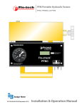
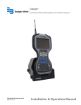
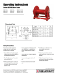
Electronic Preset Meter
Model EPM-3, RF 2.4 GHz
IOM-197-02-EN (November 2012)
53400-197 Rev. 2
Installation & Operation Manual
Electronic Preset Meter Model EPM-3, RF 2.4 GHz
Page ii
November 2012
Installation & Operation Manual
CONTENTS
SAFETY . . . . . . . . . . . . . . . . . . . . . . . . . . . . . . . . . . . . . . . . . . . . . . . . . . . . . . . . . . . . . .5
Explosion and Fire Hazards . . . . . . . . . . . . . . . . . . . . . . . . . . . . . . . . . . . . . . . . . . . . . . . . 5
Meter Hazards . . . . . . . . . . . . . . . . . . . . . . . . . . . . . . . . . . . . . . . . . . . . . . . . . . . . . . . . 5
ELECTRONIC PRESET METER DESCRIPTION . . . . . . . . . . . . . . . . . . . . . . . . . . . . . . . . . . . . . . 6
Disclaimer . . . . . . . . . . . . . . . . . . . . . . . . . . . . . . . . . . . . . . . . . . . . . . . . . . . . . . . . . . 6
Product Identification Information . . . . . . . . . . . . . . . . . . . . . . . . . . . . . . . . . . . . . . . . . . . 6
Certification . . . . . . . . . . . . . . . . . . . . . . . . . . . . . . . . . . . . . . . . . . . . . . . . . . . . . . . . . 6
OPERATION . . . . . . . . . . . . . . . . . . . . . . . . . . . . . . . . . . . . . . . . . . . . . . . . . . . . . . . . . . . 7
Meter Buttons . . . . . . . . . . . . . . . . . . . . . . . . . . . . . . . . . . . . . . . . . . . . . . . . . . . . . . . . 7
LCD Display . . . . . . . . . . . . . . . . . . . . . . . . . . . . . . . . . . . . . . . . . . . . . . . . . . . . . . . . . 7
METER INSTALLATION . . . . . . . . . . . . . . . . . . . . . . . . . . . . . . . . . . . . . . . . . . . . . . . . . . . . 8
Relieve System Pressure . . . . . . . . . . . . . . . . . . . . . . . . . . . . . . . . . . . . . . . . . . . . . . . . . 8
Grounding . . . . . . . . . . . . . . . . . . . . . . . . . . . . . . . . . . . . . . . . . . . . . . . . . . . . . . . . . . 8
Flushing Procedure . . . . . . . . . . . . . . . . . . . . . . . . . . . . . . . . . . . . . . . . . . . . . . . . . . . . 8
Apply Meter to Hose . . . . . . . . . . . . . . . . . . . . . . . . . . . . . . . . . . . . . . . . . . . . . . . . . . . . 9
Apply Nozzle to Meter . . . . . . . . . . . . . . . . . . . . . . . . . . . . . . . . . . . . . . . . . . . . . . . . . . . 9
METER OPERATION, RF MODE . . . . . . . . . . . . . . . . . . . . . . . . . . . . . . . . . . . . . . . . . . . . . . 10
Connecting to an FMS Network . . . . . . . . . . . . . . . . . . . . . . . . . . . . . . . . . . . . . . . . . . . . 10
History Icon . . . . . . . . . . . . . . . . . . . . . . . . . . . . . . . . . . . . . . . . . . . . . . . . . . . . . . . . 11
Error Codes . . . . . . . . . . . . . . . . . . . . . . . . . . . . . . . . . . . . . . . . . . . . . . . . . . . . . . . . . 11
METER OPERATION, EPM MODE . . . . . . . . . . . . . . . . . . . . . . . . . . . . . . . . . . . . . . . . . . . . 12
EPM Manual Mode . . . . . . . . . . . . . . . . . . . . . . . . . . . . . . . . . . . . . . . . . . . . . . . . . . . . 12
EPM Batch Mode . . . . . . . . . . . . . . . . . . . . . . . . . . . . . . . . . . . . . . . . . . . . . . . . . . . . . 12
Return to RF Mode . . . . . . . . . . . . . . . . . . . . . . . . . . . . . . . . . . . . . . . . . . . . . . . . . . . . 13
OPERATING MODE FUNCTIONS . . . . . . . . . . . . . . . . . . . . . . . . . . . . . . . . . . . . . . . . . . . . . 14
Resettable/Accumulated Totals . . . . . . . . . . . . . . . . . . . . . . . . . . . . . . . . . . . . . . . . . . . . 14
Emergency Override . . . . . . . . . . . . . . . . . . . . . . . . . . . . . . . . . . . . . . . . . . . . . . . . . . . 14
CALCULATING THE SCALE FACTOR . . . . . . . . . . . . . . . . . . . . . . . . . . . . . . . . . . . . . . . . . . . 15
Viewing the Current Scale Factor . . . . . . . . . . . . . . . . . . . . . . . . . . . . . . . . . . . . . . . . . . . 15
Absolute Scale Factor . . . . . . . . . . . . . . . . . . . . . . . . . . . . . . . . . . . . . . . . . . . . . . . . . . 15
CHANGING FACTORY SETTINGS . . . . . . . . . . . . . . . . . . . . . . . . . . . . . . . . . . . . . . . . . . . . 17
Verifying Firmware Version . . . . . . . . . . . . . . . . . . . . . . . . . . . . . . . . . . . . . . . . . . . . . . . 17
Using the Programming Feature . . . . . . . . . . . . . . . . . . . . . . . . . . . . . . . . . . . . . . . . . . . 17
Changing the Unit of Measure . . . . . . . . . . . . . . . . . . . . . . . . . . . . . . . . . . . . . . . . . . . . 17
Changing the Scale Factor . . . . . . . . . . . . . . . . . . . . . . . . . . . . . . . . . . . . . . . . . . . . . . . 18
Verifying Changes . . . . . . . . . . . . . . . . . . . . . . . . . . . . . . . . . . . . . . . . . . . . . . . . . . . . 18
Enabling or Disabling the EPM (Manual) Mode . . . . . . . . . . . . . . . . . . . . . . . . . . . . . . . . . . 18
Network Program . . . . . . . . . . . . . . . . . . . . . . . . . . . . . . . . . . . . . . . . . . . . . . . . . . . . 19
Power Level Display . . . . . . . . . . . . . . . . . . . . . . . . . . . . . . . . . . . . . . . . . . . . . . . . . . . 19
November 2012
Page iii
Electronic Preset Meter Model EPM-3, RF 2.4 GHz
DIMENSIONS . . . . . . . . . . . . . . . . . . . . . . . . . . . . . . . . . . . . . . . . . . . . . . . . . . . . . . . . . 20
SPECIFICATIONS . . . . . . . . . . . . . . . . . . . . . . . . . . . . . . . . . . . . . . . . . . . . . . . . . . . . . . . 20
PARTS LIST . . . . . . . . . . . . . . . . . . . . . . . . . . . . . . . . . . . . . . . . . . . . . . . . . . . . . . . . . . 21
TROUBLESHOOTING . . . . . . . . . . . . . . . . . . . . . . . . . . . . . . . . . . . . . . . . . . . . . . . . . . . . 24
MAINTENANCE . . . . . . . . . . . . . . . . . . . . . . . . . . . . . . . . . . . . . . . . . . . . . . . . . . . . . . . 25
Low Battery Indicators . . . . . . . . . . . . . . . . . . . . . . . . . . . . . . . . . . . . . . . . . . . . . . . . . 25
Changing the Batteries . . . . . . . . . . . . . . . . . . . . . . . . . . . . . . . . . . . . . . . . . . . . . . . . . 25
Page iv
November 2012
Installation & Operation Manual
SAFETY
Explosion and Fire Hazards
Improper grounding, poor ventilation, open flames or sparks can cause a hazardous condition and result in an explosion or
fire and cause serious injury.
• Be sure the fluid system is properly grounded. See your pump instruction manual for details.
• If there is static sparking or if you feel an electric shock while using the meter, stop dispensing immediately. Identify and
correct the problem before continuing.
• Provide fresh air ventilation. This will avoid the buildup of fumes from the fluid being dispensed.
• Do not smoke while dispensing flammable fluids.
• Keep the dispensing area free of debris including solvents, rags and spilled gasoline.
Meter Hazards
Equipment misuse can cause the meter to rupture or malfunction and cause serious injury.
• This equipment is for professional use only.
• Read all instructions, tags and labels before operating the equipment.
• Use the equipment only for its intended purpose.
• Do NOT modify or alter the equipment.
• Do NOT leave equipment unattended while dispensing.
• Check equipment daily. Repair or replace worn or damaged parts immediately.
• Do NOT exceed the maximum working pressure level of the lowest rated system component.
• Use only extensions and nozzles that are designed for use with this equipment.
• Use only fluids and solvents that are compatible with the equipment. Read all fluid and solvent manufacturer’s warnings.
• Tighten all fluid connections before operating this equipment.
• Do NOT stop or deflect leaks with hands, body, gloves or rags.
• Do NOT dispense towards any person or any part of the body.
• Do NOT place hands or fingers over the end of or into the dispense valve.
• Comply with all local, state, and federal fire, electrical and safety regulations.
• Use of this product in a manner other than specified in this manual may result in impaired operation or damage
to equipment.
November 2012
Page 5
Electronic Preset Meter Model EPM-3, RF 2.4 GHz
ELECTRONIC PRESET METER DESCRIPTION
Disclaimer
The user/purchaser is expected to read and understand the information provided in this manual, follow any listed Safety
Precautions and Instructions and keep this manual with the equipment for future reference.
The information in this manual has been carefully checked and is believed to be entirely reliable and consistent with the
product described. However, no responsibility is assumed for inaccuracies, nor does Badger Meter Inc. assume any liability
arising out of the application and use of the equipment described.
Product Identification Information
Record the product identification numbers from the nameplate here.
Model Number _______
Serial Number
_______
Tag Number
_______(if applicable)
Certification
•
•
•
•
Contains FCC ID: S4GEM35XB
Contains IC: 8735A-EM35XB
FCC CERTIFIED, PART 15, SUB-PART C
CE0681 EC-R&TTE Certified
This device complies with Part 15 of the FCC Rules. Operation is subject to the following two conditions: (1) this device may
not cause harmful interference, and (2) this device must accept any interference received, including interference that may
cause undesired operation.
To satisfy FCC RF exposure requirements for mobile transmitting devices, a separation distance of 20 cm or more
should be maintained between the antenna of this device and persons during operation. To ensure compliance,
operations at closer distances than this are not recommended.
Page 6
November 2012
Installation & Operation Manual
OPERATION
The Electronic Preset Meter RF3 (EPM RF3) is equipped with RF (radio frequency) communications to communicate with a
fluid management system keypad to get authorization and dispense information. This is referred to in the manual as the
RF Mode.
The meter can also be run as a standard EPM. This is referred to in the manual as the EPM Mode. This is intended for start-up
purposes or when the fluid management system is not in use.
Once a work order has been entered at the keypad, the operator simply pushes the RESET button on the meter to start
communications between the meter and the keypad. The meter receives authorization from the keypad to unlock and the
dispense batch quantity. When the trigger is pulled the preset dispense batch quantity dispenses.
The meter automatically shuts off when the dispense batch quantity has been reached.
A Topoff feature allows additional fluid to be dispensed and tracked after the batch quantity has been dispensed.
Upon completion of the dispense, the operator presses the RESET button. The meter then locks, prohibiting any unauthorized
dispense of fluid to occur, and the dispense quantity is sent to the keypad.
Meter Buttons
10, 1, 0.1
TOTAL
AUTO
RESET
SHUTOFF
or
STOP
Used to enter the dispense Batch quantity when
in the EPM Mode. These buttons are NOT used in
RF Mode.
Used to display the accumulated total of fluid
dispensed, as well as the re-settable total.
Used to enter and exit the manual or batch mode
when in EPM mode. This button is NOT used in
RF mode.
• Used to initiate RF communications from the
meter to the Keypad.
• Used in EPM mode to clear the previous
batch.
• Used to reset the re-settable total dispensed
while pressing the TOTAL button.
Used to stop the flow through an Emergency
Override.
LCD Display
2
1
7
November 2012
6
5
4
3
1
Displays resettable total, accumulated total and scale
factor
2
Displays unit of measure
3
Arrows flash when RF communication is in progress with
the keypad
4
Preset Batch quantity
5
History Icon
6
AUTO is an indicator of being in EPM mode
7
Low Battery Icon
Page 7
Electronic Preset Meter Model EPM-3, RF 2.4 GHz
METER INSTALLATION
Relieve System Pressure
1. Turn off the power supply to the pump or close the shutoff valve.
2. Dispense any fluid in the system into a waste container by opening the meter(s).
3. Open all bleed-type master air valves and fluid meter(s) in the system.
4. Leave the meter(s) open until ready to pressurize the system.
Pressurized Equipment
This equipment stays pressurized until the pressure is manually relieved. To reduce the risk of injury from fluid spray from the
meter follow the Pressure Relief Procedures when you:
• Are instructed to relieve pressure
• Stop dispensing
• Check, clean, or service any system equipment
• Clean or install nozzles
Grounding
Grounding reduces the risk of static sparking. Ground all system components according to local, state, and federal codes.
Consult the pump user's manual and other system components to ground the following:
• Pump: follow manufacturer's recommendations
• Air and Fluid Hoses: use only grounded hoses
• Air Compressor: follow manufacturers recommendations
• Fluid Supply Container: follow the local code
Possible Explosion and Fire
Movement of fluids through the dispensing system creates static electricity. Static electricity can cause volatile fumes
resulting in an explosion and fire. The dispensing system must be grounded.
Flushing Procedure
NNOTE: If the system has multiple dispense positions, begin at the position farthest from the pump and move towards the
pump.
If this installation is new or if the fluid in the lines is contaminated, flush the system before installing the meter(s).
1. Close fluid dispense valves at every position.
2. Once the main fluid outlet valve at the pump is closed, the air pressure to the pump motor is properly adjusted and
the air valve is opened.
3. Slowly open the main fluid valve.
4. Place the hose end in a waste container. Make sure hose is secure so no fluid leaks during flushing.
5. Slowly open the dispense valve and allow enough oil to pass through it to ensure that the system is clean.
6. Close the valve and repeat for all dispense positions.
Page 8
November 2012
Installation & Operation Manual
Apply Meter to Hose
Close the drain valve before starting this procedure.
1. Attach a swivel to the meter. Apply thread sealant to the male end of hose.
Recommended sealant is Loctite® 243.
2. Insert the metal end of the hose into the swivel. Tighten completely with an open
ended, adjustable, wrench.
NNOTE: The threaded end of the meter always has female threads. The metal end of the
hose must have male threads.
Apply thread sealant, Loctite® 243, or equivalent, to the male end.
The inlet and outlet swivel connections are either 1/2" NPT or 1/2" BSPP, depending
on meter model.
Apply Nozzle to Meter
1. On the opposite end, apply sealant to the end of the nozzle. Recommended sealant is
Loctite® 243.
2. Thread the nozzle onto the meter. Screw it in tightly with an open ended, adjustable,
wrench.
3. Open all dispense position shut-off valves. Start the pump to pressurize the system.
4. Before use, to ensure accuracy, purge all air from the fluid lines and dispense valve(s).
November 2012
Page 9
Electronic Preset Meter Model EPM-3, RF 2.4 GHz
METER OPERATION, RF MODE
Connecting to an FMS Network
When the meter is first installed, it must be attached to the network with the keypad powered ON. Also, when the keypad is
replaced, the meter must be reconnected.
1. Press and hold the 10 key.
2. While holding down the 10 key, press and release the RESET button.
The meter will then search for and connect to the network.
When the battery pack is attached to the meter, it automatically enters the RF Mode. The trigger is in the locked-out position.
No fluid can be dispensed by the meter until a dispense order is received from the keypad.
1. Pressing the meter RESET button causes communication to occur between the meter
and the keypad.
Two arrows in the lower right hand corner of the meter screen flash. This indicates
communication is in progress between the meter and keypad.
Arrows
2. When the communication is complete the trigger unlocks and the batch quantity is
displayed.
Batch Quantity
3. Pull the trigger to the full, up, position to begin the fluid flow.
• The solenoid valve automatically locks the dispensing valve in the full open
position. The trigger falls back to the closed position.
• It is not necessary to continue to hold the trigger.
• After the batch quantity is dispensed, the flow automatically shuts off.
Do NOT press the RESET button before topping off.
If the RESET button is pressed, the meter returns to a locked-out position and does not allow additional fluid to be dispensed until a
valid dispense order is received from the RF system.
4. You have the option to top off the tank after the batch quantity has been dispensed.
a. To top off, pull the trigger to begin the flow.
b. Release the trigger when the desired amount has been dispensed.
5. Press the RESET button when finished to complete the dispense order.
a. The total quantity dispensed is transmitted to the RF system.
b. The meter returns to the locked position.
c. The meter is now ready to receive another dispense order from the RF system.
NNOTE: If the original communication fails, the meter automatically attempts to communicate with the RF system by
resending the Dispense Result three times, 30 seconds apart.
6. If the meter is unable to communicate a dispense result, the History icon lights.
Page 10
November 2012
Installation & Operation Manual
History Icon
The History icon indicates there is dispense result information that has not been
communicated to the keypad to complete a work order.
To send the dispense result information to the keypad, press the RESET button to initiate
communication.
History Icon
Error Codes
The meter has several Error Codes that may display. These provide indication, at the meter, that there is an error in
communication between the meter and keypad.
F01
The meter radio is not working.
To clear the error, press the RESET button on the meter.
F02
The meter is not configured to a keypad.
To clear the error code, press the RESET button on the meter.
Verify that the meter radio address is configured properly.
F03
System busy.
To clear the error, press the RESET button on the meter.
F08
Meter lost connection to network.
Out of range—network connection lost.
Keypad not powered.
Meter moved out of range of keypad.
F09
Meter not connected to a network.
First time being powered up.
Network selected is not available.
SF0
(Scale Factor 0)
The Scale Factor setting for the meter is set to 0.000.
All other
Error Codes
Are for factory purposes only.
November 2012
To input a valid Scale Factor for the meter follow the instructions in the Change Factory Settings section
of this manual.
To clear the meter, press RESET.
Page 11
Electronic Preset Meter Model EPM-3, RF 2.4 GHz
METER OPERATION, EPM MODE
The meter can be put in EPM Mode for startup purposes by entering the Manual Mode key sequence. Consult the factory for
the sequence.
The AUTO icon displays, indicating the meter is in the EPM Mode. The solenoid valve unlocks and the meter can now be used
as a Standard Preset Batch Meter.
NNOTE: The AUTO button is used to toggle between Manual Mode and Batch Mode.
EPM Manual Mode
1. Pull the trigger to begin the flow.
2. The display shows the amount dispensed.
3. When the desired amount has been dispensed, release the trigger to stop the flow.
4. Press the RESET button once to reset the counter display to zero.
Amount Dispensed
EPM Batch Mode
To enter the Batch Mode from the Manual Mode, press the AUTO button.
When in the Batch Mode, the batch quantity displays in the lower right-hand corner of the
screen.
The meter is now in Batch Mode.
Batch Quantity
1. Change the batch size by pressing the 10, 1 and/or 0.1 buttons.
a. Press the 10 button to increase the batch amount in increments of 10 units.
b. Press the 1 button to increase the batch amount in increments of 1 unit.
c. Press the 0.1 button to increase the batch amount in increments of 0.1 units.
2. Pull the trigger to begin the flow.
Batch Size
The meter solenoid valve automatically locks the dispensing valve in the full open position.
The trigger falls back to the closed position.
The meter always locks in the maximum open position.
After the batch quantity is dispensed, the flow automatically shuts off.
NNOTE: For RF and BATCH programming, the meter automatically shuts off if the trigger is pulled and the meter does not
sense any flow.
Also, in case of an emergency or to interrupt a batch, the meter is equipped with an Emergency Override. (Refer to
the "Emergency Override" on page 14 section of this manual.)
Page 12
November 2012
Installation & Operation Manual
Return to RF Mode
To return to the RF Mode from the EPM Mode:
1. If the batch quantity on the display is not zero, press the RESET button to zero the
display.
2. Press the RESET button with a zero batch quantity on the display.
You’ll see the flashing arrows indicating the meter is communicating with the
RF System.
Arrows
3. When communication is complete, the meter returns to the RF Mode and the
trigger locks.
To manually reset the meter to the RF Mode:
1. If the batch quantity on the display is not zero, press the RESET button to zero the
display
2. Re-enter the Manual Mode key sequence.
November 2012
Page 13
Electronic Preset Meter Model EPM-3, RF 2.4 GHz
OPERATING MODE FUNCTIONS
These functions operate the same in RF Mode and EPM Mode.
Resettable/Accumulated Totals
The meter has two flow totalizers. One is Resettable Total the other is Accumulated Total.
1. Press and hold the TOTAL button to see the Accumulated Total.
2. Continue holding the TOTAL button for three seconds to see the Resettable Total.
RESETTOTAL displays the total fluid dispensed since the Resettable Total was last set back
to zero.
3. Press the RESET button while viewing RESETTOTAL to set it back to zero.
Resettable Total
4. Release the TOTAL button to return to the operating display.
NNOTE: The Accumulated Total cannot be reset unless the you change the unit setting from English units to metric units or
from metric to English units. (Refer to the Change Factory Settings, Change Unit of Measure section of this manual).
Emergency Override
In case of an emergency or to interrupt a batch, the meter is equipped with an Emergency Override.
1. Press the red O button to activate the Emergency Override.
The override closes the valve, immediately stopping fluid flow.
2. Batching can continue after an Emergency Override by pulling up on the trigger.
Page 14
November 2012
Installation & Operation Manual
CALCULATING THE SCALE FACTOR
A Scale Factor is a number used to adjust meter accuracy. The Scale Factor is set at the factory using motor oil with a viscosity
of 10W.
The primary use for Scale Factor recalibration is to batch fluids with different viscosities. If the fluid has a lower viscosity, more
fluid can slip past the meter gears without being detected. Changing the Scale Factor adjusts the meter to compensate for
the loss.
The meter multiplies each pulse by the Scale Factor number to correct the accuracy when it converts to the specified units.
The reading is then always correct.
For an approximate Scale Factor for fluids of different viscosities, consult the charts on the next page.
NNOTE: The meter’s original Scale Factor was written on the trigger when it was calibrated at the factory. It may have been
revised after field installation. Use the Scale Factor showing on the display, not the one written on the trigger.
IMPORTANT
Changing the Scale Factor changes the accuracy of the meter, potentially causing over-dispensing or under-dispensing of the liquid.
Viewing the Current Scale Factor
To view the current Scale Factor, press and hold the TOTAL button and the AUTO button at the same time.
Absolute Scale Factor
For absolute Scale Factor, perform this test:
1. Run a measured amount of fluid through the meter.
2. If the meter delivers 4.20 quarts and the display shows only 4.00 quarts, then the Scale Factor needs to be adjusted.
3. Divide what the meter delivered (4.20) by what the display shows (4.00). You get an error factor of (1.05).
The existing Scale Factor is 1.0123.
4. To calculate a new factor: 1.0123 (existing Scale Factor) x 1.05 (error factor) = 1.0629 (new Scale Factor).
5. Enter that number as described in the Change Scale Factor section of this manual.
NNOTE: Use the Scale Factor showing on the display, not one written on the trigger.
November 2012
Page 15
Electronic Preset Meter Model EPM-3, RF 2.4 GHz
Figure 6: Chart of Approximate Scale Factors for Fluids of Different Viscosities
Fluid
Viscosity
Scale Factor
Water/Anti-Freeze
5
1.044
Anti-Freeze
18
1.007
Brake Fluid
42
1.004
ATF
80
1.002
10W
140
1.000
80W-90
450
0.999
140W
1800
0.993
Table 2: Samples of Fluids, Viscosities and Scale Factors
Page 16
November 2012
Installation & Operation Manual
CHANGING FACTORY SETTINGS
Each meter is calibrated at the factory for use with motor oil (refer to the Change Scale Factor section of this manual). The Unit
of Measure is also selected prior to shipment.
Verifying Firmware Version
To check the firmware version and code checksum, press and hold the TOTAL and 1 buttons at the same time.
The last two digits on the lower right are the firmware version.
Using the Programming Feature
Use the Programming feature to change the factory settings:
Push the AUTO and TOTAL buttons at the same time and hold for 2 seconds to bring up
the Program PIN screen. To enter your PIN:
1. Press and hold the 10 button to select first digit of PIN.
2. Press and hold the 1 button to select second digit of PIN.
3. Press and hold the 0.1 button to select third digit of PIN.
4. If necessary, hold down the TOTAL key and press 10, 1, or 0.1 to decrement a PIN digit.
5. Press RESET to confirm PIN and enter the programming mode with Scale Factor and
Unit of Measure screen displayed.
6. Push and hold AUTO and TOTAL for 2 seconds to exit the programming mode.
Changing the Unit of Measure
The meter has four Units of Measure:
• Pint (PT)
• Quart (QT)
• Gallon (GAL)
• Liter (L)
Changing the Unit of Measure from metric to English or from English to metric clears the Resettable Total and the
Accumulated Total.
The current Unit of Measure is flashing when you enter the Programming Mode. To change
the Unit of Measure:
1. Press and hold the TOTAL button until the Unit of Measure you want is displayed.
2. Press the RESET button to save your selection.
3. If you select L (Liters), the decimal point begins to flash. Press the TOTAL button to
change the decimal point to either a period or a comma.
4. If no Scale Factor changes are necessary, press and hold the TOTAL and AUTO buttons
until the display flashes three times, then goes blank
OR
Press the RESET button to advance to the EPM Manual Mode Enable screen.
November 2012
Page 17
Electronic Preset Meter Model EPM-3, RF 2.4 GHz
Changing the Scale Factor
IMPORTANT
Changing the Scale Factor changes the accuracy of the meter, potentially causing over-dispensing or under-dispensing of the liquid.
This has the potential to cause a mechanical breakdown.
Scale Factor Digits
1. Press the RESET button to advance through the Scale Factor digits.
2. Press the TOTAL button to change the selected number.
NNOTE: All digits can be scrolled between 0 and 9 except the first. It can only be scrolled
from 0 to 1 or from 1 to 0.
Unit of Measure
Scale Factor Digits
3. Press the RESET button advance to the next number in Scale Factor.
4. Repeat steps 2 and 3 for all five digits in Scale Factor.
5. If no Scale Factor changes are necessary, press and hold the TOTAL and AUTO buttons
until the display flashes three times, then goes blank
OR
Press the RESET button to advance to the EPM Manual Mode Enable screen.
Verifying Changes
Press and hold down the TOTAL and AUTO buttons at the same time to verify that the Scale Factor is correct.
Enabling or Disabling the EPM (Manual) Mode
To enable or disable the EPM mode:
1. Press the RESET button to advance to the AUTO icon on the display. There will be no
other icons flashing on the display.
2. Press the AUTO button to toggle the AUTO icon on and off.
When the icon is turned on the meter can be put in EPM mode through the special key
sequence on the meter keypad. When the AUTO icon is turned off the key sequence is
disabled and the meter cannot be put in EPM mode.
3. Press the RESET button to advance to the Network Program screen.
.
Page 18
November 2012
Installation & Operation Manual
Network Program
The Radio Network is used to differentiate multiple FMS networks. For standard
installations the default setting of zero will not need to be changed.
The Network setting must be between 0 and 255. To change the network setting:
1. Press 1 to increment network setting or press 0.1 to decrement network setting.
2. Press RESET to advance to the Power Level Display screen.
NNOTE: When NOT in programming mode, you can view the Radio Network by holding down the TOTAL button while
pressing the 10 button.
Power Level Display
1. The radio power level is set at the factory. The display is for validation purposes only.
2. Press RESET to return to Scale Factor and Unit of Measure screen.
NNOTE: When NOT in programming mode, you can view the Power Level by holding down the TOTAL button while pressing
the 1 button.
Saving Changes
To save your changes and exit the programming mode:
1. Press and hold down the TOTAL and AUTO buttons at the same time. The display will flash 3 times and go blank.
2. Press the RESET button to turn on the display.
November 2012
Page 19
Electronic Preset Meter Model EPM-3, RF 2.4 GHz
DIMENSIONS
SPECIFICATIONS
Maximum Flow *
10 gpm (38 lpm)
Minimum Flow *
0.25 gpm (1 lpm)
Operating Pressure (Maximum)
1000 psi (67 bar)
Operating Pressure (Minimum)
5 psi (0.35 bar)
Operating Temperature (Maximum)
120° F (50° C)
Operating Temperature (Minimum)
20° F (–5° C)
Accuracy – Oils
+/– 0.5% (+/– 0.5%)
Accuracy – Anti-freeze
+/– 1.5% (+/– 1.5%)
5-Digit LCD Display, 10 mm high x 5 mm wide
Quarts (liters), pints, gallons
Inlet and Outlet Connections
1/2" NPT (1/2" BSPP)
* Tested with DTE-25 motor oil at ambient temperature. Minimum/maximum flow range will vary with fluid viscosity.
Page 20
November 2012
Installation & Operation Manual
PARTS LIST
November 2012
Item #
Description
Part Number
1
Battery holder assembly
64103-026
2
Bottom case with screws and radio
64103-029
3
Solenoid
64786-002
Page 21
Electronic Preset Meter Model EPM-3, RF 2.4 GHz
1
2
3
Page 22
Item #
Description
Part Number
1
Rubber boot
65546-001
2
Display assembly
64103-023
3
RF register assembly
64103-030
Not Shown
Swivel, NPT AFLAS
64082-007
November 2012
Installation & Operation Manual
2
1
3
November 2012
Item #
Description
Part Number
1
Valve assembly – AFLAS
64103-020
2
LCP gear set with AFLAS o-ring
62896-003
3
Trigger assembly
64103-015
Page 23
Electronic Preset Meter Model EPM-3, RF 2.4 GHz
TROUBLESHOOTING
Pressurized Equipment
Relieve the pressure prior to checking or repairing the meter. Make sure all valves, controls and pumps are operating correctly.
Symptom
Possible Cause
Remedy
Battery Icon is
displayed
Batteries are low
Replace batteries
Display Blank
Meter asleep
Press RESET button
Loose battery connection
• Remove battery pack and check battery connection
• Press RESET button
Batteries dead
• Replace batteries
• Press RESET button
Meter not in AUTO mode
Press AUTO button and program batch size
Meter not reset after prior batch
Press RESET button
Low batteries
• Check for battery icon
• Replace batteries
• Press RESET button
Filter is clogged
Clean or replace the filter in the swivel nut
Pump pressure is low
Turn up the pump pressure
Foreign material is jamming meter
Contact your local distributor for repair
Scale factor not correct for fluid
Enter program mode, check and reset program factor
Meter does not latch
for batching
Slow or no fluid flow
Meter inaccurate
Page 24
November 2012
Installation & Operation Manual
MAINTENANCE
Low Battery Indicators
When the batteries need changing, a progression of warnings appears on the meter screen.
First Warning
The Low Battery icon appears in the lower left corner of the display. That means the
batteries are low and need to be changed when the icon appears.
Second Warning
The Battery icon flashes. The battery power is too low and meter functions are disabled.
Low Battery Icon
Changing the Batteries
The battery compartment is located in the lower case on the backside of the trigger guard.
1. Position the unit face down.
2. Unscrew the two screws. Remove the battery door to expose the batteries.
3. Replace the old batteries with 4 AA alkaline batteries.
NNOTE: Battery polarity markings are inside battery compartment.
4. Dispose of used batteries properly, according to local regulations.
NNOTE: Changing the batteries does not affect any of the programmed values
or totals.
November 2012
Page 25
Electronic Preset Meter Model EPM-3, RF 2.4 GHz
INTENTIONAL BLANK PAGE
Page 26
November 2012
Installation & Operation Manual
INTENTIONAL BLANK PAGE
November 2012
Page 27
Trademarks appearing in this document are the property of their respective entities.
Due to continuous research, product improvements and enhancements, Badger Meter reserves the right to change product or system specifications without notice, except to the extent an outstanding
contractual obligation exists. © 2012 Badger Meter, Inc. All rights reserved.
www.badgermeter.com
The Americas | Badger Meter | 4545 West Brown Deer Rd | PO Box 245036 | Milwaukee, WI 53224-9536 | 800-876-3837 | 414-355-0400
México | Badger Meter de las Americas, S.A. de C.V. | Pedro Luis Ogazón N°32 | Esq. Angelina N°24 | Colonia Guadalupe Inn | CP 01050 | México, DF | México | +52-55-5662-0882
Europe, Middle East and Africa | Badger Meter Europa GmbH | Nurtinger Str 76 | 72639 Neuffen | Germany | +49-7025-9208-0
Czech Republic | Badger Meter Czech Republic s.r.o. | Maříkova 2082/26 | 621 00 Brno, Czech Republic | +420-5-41420411
Slovakia | Badger Meter Slovakia s.r.o. | Racianska 109/B | 831 02 Bratislava, Slovakia | +421-2-44 63 83 01
Asia Pacific | Badger Meter | 80 Marine Parade Rd | 21-04 Parkway Parade | Singapore 449269 | +65-63464836
China | Badger Meter | Rm 501, N° 11 Longyue Apartment | N° 180 Longjin Rd, Jiuting Songjiang District | Shanghai, China | 201615 | +86-21-5763 5412