1
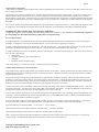
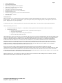
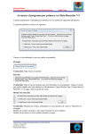
Instruction Manual for the Micro GPS Expander V4
Document Version 1.3
Model # GPS-V4
Thank you for your purchase! This instruction manual will guide you through the installation and operation of your GPS
V4. Please read the entire manual carefully before proceeding. If, after you read the manual, you have further
questions or problems, see the Support page on http://www.eagletreesystems.com for additional information, or email us at
[email protected].
Intended Uses
The GPS Expander V4 (the GPS) is intended for use exclusively in model planes, boats and cars. Other uses are not supported.
Features
The GPS is designed to be used with all present Eagle Tree recording, OSD and wireless telemetry products. The GPS updates at 10Hz, consumes
very little power, and has battery backup for quick hot and warm starts.
Our Data Recorder software includes support for Google Earth, including live mode display, and Google Earth Track support for logged data.
The GPS includes onboard filtering, as well as a toroid ring filter, to improve signal reception, especially when used in conjunction with First Person
View video transmitters.
The GPS’s built-in LED indicates when a 3D fix has been attained, for convenient usage. The LED flashes UNTIL a 3D fix is attained, then stops
flashing.
The GPS is tiny and lightweight, making it perfect where weight and size are issues. See the Specifications section below for more information.
With our Windows software, and now with Google Earth™ software, your GPS data can be easily and fully visualized.
Supported Products
The GPS is compatible with the Eagle Tree Systems eLogger V3, Flight Data Recorder V2, Car Data Recorders and Boat Data Recorders with
firmware version 5.55 or higher. It is also fully compatible with Seagull Dashboards with firmware version 4.76 or higher. If you have
firmware lower than this version, go to our support website, and download the latest software, which will update the firmware of your device.
Packing List
Your package should include the following: the GPS, and a printed version of this manual. Please check your packaging for printed addenda to this
manual which may be included if changes were made after printing.
How the GPS Works
When coupled The GPS uses satellite information to determine position, speed, altitude, course,
distance to operator, and UTC time.
Connecting the GPS to the Recorder
The 4 wire connector attached to the GPS plugs into the rightmost port of your Data Recorder as
shown in Figure 1. Make sure that you connect it in the correct location on the recorder, and with the
correct polarity!
Connecting the GPS to the eLogger V3
The 4 wire connector attached to the GPS plugs into the eLogger V3 as shown in Figure 2. Make
sure that you connect it in the correct location on the recorder, and with the correct polarity!
Note: The GPS draws significant current from the eLogger. When the eLogger is powered by a higher voltage pack, such as an 8s or larger
pack, or a pack above 30 volts, the eLogger’s regulator may shut off after a short period when
used with the GPS. Please use our “Battery Backup Harness”, part number CAB-BAT-BACK, or
build your own, to provide supplemental power to the eLogger if you encounter this issue.
Installing the GPS in your Model
The GPS should be mounted with Velcro in your vehicle so that the top part (with the label) is facing
toward the sky. Normally, it is satisfactory to have the GPS inside the vehicle, since the skin of most
vehicles is relatively thin. If you have difficulty getting a signal, try mounting it externally to the
vehicle.
Copyright © 2005-2010 Eagle Tree Systems, LLC
http://www.eagletreesystems.com
Page 2
Setting up the GPS with your Recorder
To use the GPS, first ensure that you have the latest version of the Windows application (the application). Application updates are available as a
free download from the support page of our website, for our customers.
When configured with the recorder, the GPS will record all GPS parameters as listed in the features section above, and the data is also available on
the Seagull Wireless Dashboard.
If you wish to record GPS data, choose “Hardware, Choose Parameters to Log in the Recorder” in the app, and select “GPS Parameters”. This
indicates to the recorder that GPS data should be recorded. Note that you DO NOT need to record GPS data to see it live on the Seagull
Dashboard.
If you wish the recorder to only start recording GPS (and all other) parameters after a GPS Fix is acquired, select “Advanced, Set Logging Triggers”
and select the option to trigger on GPS Fix Acquire. NOTE: If this option is triggered, the LED will flash in “pause” state (two quick flashes
repeated) until a fix is acquired. This is a handy way to tell when the fix has been acquired, if you do not use the Seagull Wireless Dashboard. Also
note that the Recorder will not log any parameters if the GPS is not connected or has not acquired a fix, when this option is selected.
To configure the application to display the GPS data, choose “Software, Choose Instruments to Display on PC Screen” in the application, and select
the GPS Parameters you wish to see. Here is a description of the parameters available:
GPS Coordinates – this option displays the Latitude and Longitude parameters of the flight. These parameters are displayed just below the
playback controls in the application.
Show GPS In DMS Mode – when this checkbox is checked, the GPS Latitude and Longitude are displayed in Degrees:Minutes:Seconds.Seconds
mode. When this box is unchecked, the parameters area displayed in Degrees:Minutes.Minutes mode.
GPS UTC Time – this option displays the UTC time as received from the GPS.
this option is selected.
The UTC is displayed in the Total Length/Progress window when
GPS Altimeter Gauge/Numeric GPS Altitude – these options display GPS altitude. Note that GPS altitude takes several minutes to stabilize, after
the GPS/recorder are powered. Also note that this altitude is above MSL (Mean Sea Level). Depending on the “Metric” button on this page, the
altitude is displayed in either feet or meters.
GPS Speed Gauge/Numeric GPS Speed – these options display GPS speed.
displayed in either MPH or K/H.
Depending on the “Metric” button on this page, the speed is
GPS Course Gauge/Numeric GPS Course – these options display the course of the vehicle, in degrees True North.
GPS Distance to Operator – this option displays the distance from the operator to the GPS. The value is reset to zero when the GPS/recorder are
powered on.
After a recording is made with the GPS, assuming GPS data is being logged, it will be displayed after data download. Note that if the recorder is
connected to your PC via USB, Live Mode will allow you to see the GPS parameters live. Just hit the “Live Mode!” button. See the section
below on graphing GPS data.
Setting up the GPS with the Seagull Dashboard
If you wish to display GPS data on your Seagull Dashboard, choose “Hardware, Choose Parameters to Display on Wireless Dashboard LCD” in the
application, and select the GPS parameters you wish to display.
After selecting the parameters, the Dashboard LCD pages will show the GPS information you selected, as well as any other parameters selected.
Note that the UTC, Lat/Lon and status parameters take up an entire LCD page each.
The GPS parameters can be selected via the Dashboard up/down buttons, as is the case with other Dashboard parameters.
If you connect your Dashboard to your laptop for real-time laptop display, the items selected in the section above will be displayed live.
Setting up the GPS with the Eagle Tree OSD Pro or OSD
If you wish to display GPS data on your Eagle Tree OSD, choose “Hardware, Choose Parameters to Display on Video OSD” in the application, and
select the GPS parameters you wish to display.
After selecting the parameters, the OSD will display GPS information you selected, as well as any other parameters selected.
Using the GPS
Now that you have the GPS installed and configured, it’s time to use it! To use it, simply move the GPS into an open area (some enclosed areas
will work also), power on your vehicle, and normally within one minute, the GPS will obtain a fix and begin recording and/or displaying information
on the Seagull Dashboard.
Copyright © 2005-2010 Eagle Tree Systems, LLC
http://www.eagletreesystems.com
Page 3
The GPS has a built-in LED, which will flash UNTIL a 3D GPS fix is attained. Once a 3D fix is attained, the LED will turn OFF. This design is to
save power, since the LED will be flashing only when a 3D fix is not attained. Note that if your GPS signal quality is not good, it is possible that
you will attain a “2D” GPS fix. The LED will still blink, but the Eagle Tree equipment will still report a fix.
Note that the next time you power off and on your vehicle, the GPS should obtain a fix in as little as one second, assuming it hasn’t been relocated a
great distance since power down.
Once a valid fix is received, the GPS data for that fix will be displayed on the Dashboard until the next fix comes in (normally once per second). If
the Dashboard does not receive a new fix within a few seconds, it will mark the Lat and Lon fields with an “*” beside the values to indicate a “stale”
fix.
If you are using the Dashboard, and have selected the GPS Status page to display, the Dashboard will display one of the following messages on the
GPS Status page when it is selected:
“No GPS Detected” – this message indicates that the system has not detected a GPS. Check connection if this error message occurs.
“Acquiring Fix” – this message indicates that the GPS is connected and detected, but has not yet gotten a fix.
“Fix Acquired” – this message indicates that the GPS has acquired a valid fix (either 2D or 3D) within the last few seconds.
Note that if you set up the GPS Status page, and selected the “Beep four times when GPS fix is first acquired” option, the Dashboard will beep four
times to indicate when a fix is first acquired.
Graphing GPS Data with Google Earth™
Our Windows application supports both Live Mode and recorded data output to Google Earth. Latitude, Longitude and Altitude (either GPS or
barometric) data are output in the Google Earth format. NOTE: Please install Windows application version 8.87 or later from our website for full
Google Earth support.
Google Earth™ Live Mode Support
To set up Google Earth Live Mode support, first select “Hardware, Live Mode Options”.
Check the “Click here to export Live Mode data to Google Earth” box if you wish to export Live Mode GPS data to Google Earth.
After clicking this box, you will be prompted to choose a Live Mode Google Earth path name. This is simply a path to a file, normally on your hard
drive, to which Live Mode will record a Google Earth compatible file in real time. You will open this file in Google Earth also.
Check the “Click here to export Altimeter altitude readings to Google Earth” box if you have a Flight system, and wish to export your Recorder's
Altimeter Sensor (barometric) altitude readings to Google Earth. Uncheck the box if you wish to send GPS Altitude data to Google Earth. Note that
exported data will tell Google Earth whether the altitude values are barometric (altitude readings are zero at ground level) or whether they are
absolute altitude from GPS (distance above MSL).
Once you have chosen the Google Earth options above, click “OK” on the Live Mode Options Dialog Box, and follow the steps below to see real
time data from your GPS in Google Earth:
1) Install Google Earth version 5.2.1.1588 or later from the Google Earth Website http://earth.google.com/
2) Start Live Mode with the Eagle Tree Windows application – this can be done with either your Recorder, your EagleEyes, or with the
Seagull Wireless Dashboard. Minimize the Windows application if desired.
3) In Google Earth, open the file that you specified above.
You should now see a live line graph of the GPS coordinates in Google Earth.
Google Earth™ Recorded Data Support
To save data in a Google Earth compatible format, simply download data from the Recorder, or capture Live Mode data, and click “File, Save for
Google Earth.”
The first time you save a file for Google Earth, the “Configure Google Earth File” page will appear. Check the “Click here to export Altimeter
altitude readings to Google Earth” box if you have a Flight system, and wish to export your Recorder's Altimeter Sensor (barometric) altitude
readings to Google Earth. Uncheck the box if you wish to send GPS Altitude data to Google Earth. Note that exported data will tell Google Earth
whether the altitude values are barometric (altitude readings are zero at ground level) or whether they are absolute altitude from GPS (distance above
MSL).
Once you have saved the Google Earth compatible file, open the same file in Google Earth (version 5.2.1.1588 or later) and the path should be
visible in Google Earth. Once loaded into Google Earth, all the powerful Google Earth visualization tools should be available with the data.
Note: With newer versions of Google Earth, if part or all of your session does not appear, it may be necessary to follow the procedure in Google
Earth below. This procedure addresses an issue that occurs when the altimeter readings collected in your data are below Google Earth’s
determination of the local elevation. Google Earth does not display data points that are below this local elevation. Note that this issue is most
common with surface applications, such as cars and boats.
•
load the KML file into Google Earth
•
right click on the KML file under the “Places” window
•
select the "Altitude" tab, and select "Relative to Ground".
Copyright © 2005-2010 Eagle Tree Systems, LLC
http://www.eagletreesystems.com
Page 4
Google Earth™ Track Support
To save data in a Google Earth Track compatible format, simply download data from the Recorder, or capture Live Mode data, and click “File, Save
Save as Google Earth Track.”
The first time you save a file for Google Earth, the “Configure Google Earth File Save Settings” page will appear. Check the “Click here to export
Altimeter altitude readings to Google Earth” box if you have a Flight system, and wish to export your Recorder's Altimeter Sensor (barometric)
altitude readings to Google Earth. Uncheck the box if you wish to send GPS Altitude data to Google Earth. Note that exported data will tell Google
Earth whether the altitude values are barometric (altitude readings are zero at ground level) or whether they are absolute altitude from GPS (distance
above MSL).
Once you have saved the Google Earth Track compatible file, open the same file in Google Earth (version 5.2.1.1588) and the path should be visible
in Google Earth. Once loaded into Google Earth, all the powerful Google Earth Track visualization tools should be available with the data.
Graphing GPS Data with the Eagle Tree Windows Application
The application supports a variety of Graphing options for GPS data, with both recorded and live data. NOTE: we recommend using Google Earth
for GPS graphing other than simple 2D position graphing without a background image.
Recorded Mode Graphing
To Graph recorded data, first load the data into the app, either from downloading from the Recorder, recording from live mode with the Seagull
Dashboard, or loading from a previously saved Data Recorder file. See the section below on graphing live mode data.
To Graph recorded GPS data in 2D, choose “Graph Data!”, and select “2D GPS Chart.” The chart will show the 2D (bird’s eye) graph of the data,
and will show the latitude and longitude positions on the axes. Note that the chart will automatically scale to fit the data.
To Graph recorded data in 3D, choose “Graph Data!”, and select “3D GPS Chart.” The Chart will show the 3D plot. The Z-Axis can be selected to
be one or more of the following:
•
GPS Altitude
•
Barometric Altitude (For Boat or Flight Systems)
•
GPS Speed
•
Pitot/Static Speed (For Flight Systems)
These choices allow you to visualize your position as compared with your speed or altitude.
Loading a Background Image for 2D and 3D Charts
The graphing software supports loading an image upon which the GPS chart can be plotted. GPS background images with GPS coordinates can be
obtained from Google Earth ™, GlobeExplorer.com™, or other internet resources. Electronic maps of the proper file format can also be loaded as
background images, of course.
The software also supports setting the upper left-hand and lower right-hand GPS coordinates of the image. This is especially useful if you will be
operating in a certain area, and wish to observe your vehicle’s path over this particular area. Loading the GPS coordinates forces the chart to scale
to the entered GPS coordinate rectangle, which causes the GPS data points to plot at the correct place within the image. Note that no points will be
plotted if the current position of the GPS falls outside the rectangle formed by the coordinates you entered.
To load an image, first click the “Load Image” button, which will bring up the image “Load a GPS Chart Background Image” window. Then, click
“Load GPS Chart Image.” This allows you to load a JPEG, BMP, or GIF image file on 2D graphs. Currently only BMP files are supported in 3D
GPS graphs, but support for more 3D image types will be added to a future version of the app.
To set the GPS coordinates of the image, enter the latitude and longitude of the upper left-hand corner of the image, and the lower right-hand corner
of the image. These coordinates must be entered in signed decimal degrees (+/-DDD.DDDDDDD) format. Note that North and East coordinates
are positive, and South and West coordinates are negative.
If you have only DMS coordinates, conversion from DMS to decimal can be done via a calculator, or from a conversion website. For example, if
you have the following coordinates in DDD MM SSSS format, you would enter the corresponding coordinates into the application:
Upper Left-hand Image Coordinates in DMS: 33° 19’ 48.00” N
44° 26’ 24.00”E
Enter the following for Upper Left-hand Coordinates in decimal format:
33.330000 44.440000
Once the Background Image and optional GPS coordinates are entered, hit OK to load the image.
NOTE: currently, when a background image is loaded into a 3D GPS chart, another software program must have been used to correctly tilt and
stretch the image. We will automatically tilt and stretch the image in a future version of the application.
Copyright © 2005-2010 Eagle Tree Systems, LLC
http://www.eagletreesystems.com
Page 5
Using GPS Charting in Live Mode
To view a 2D GPS chart of the vehicle’s real-time position, follow the below steps:
•
Connect either the Recorder or Seagull Dashboard to USB.
•
Launch the Application, and choose “Graph Data!, 2D GPS Chart.”
•
Load a background image if desired, if not already loaded.
•
Click the “Live Mode!” button on the application.
A live trail of the vehicle’s course should then appear on the 2D GPS chart.
Examining Data with Excel™ or compatible Spreadsheet Program
The GPS information is available in the .FDR (or .CDR or .BDR) files saved by the Windows Application, and these files can be viewed in Excel.
Please see the instruction manual that came with your Recorder for information on how to load the files into Excel.
The GPS specific fields in the .FDR files are as follows:
•
GPSLat/GPSLon: GPS Latitude and Longitude (decimal format). Example: 42.56205667, -72.1795
•
GPSAlt: GPS Altitude (height above MSL, in either feet or meters, depending on your units selection). Example: 38.4
•
GPSSpeed: GPS Speed (either MPH or KPH, depending on your units selection). Example: 45
•
GPSCourse: True (not magnetic) Course, in degrees. Example: 341.1
•
GPSDist: Distance of GPS Module from where it got its first fix after system powerup (in either feet or meters, depending on unit
selection). Example: 255
•
GPSUTC: UTC, converted to milliseconds. Example: 55928839
•
NumSats: Number of Satellites in view. Example: 4
•
GPSFlags: OR’d together flags of the following values: GPS Fix Valid: 1, 3D Fix: 2, GPS Data Received: 4. Example: 7
•
HDOP*10: This is the GPS’s reported “HDOP” value, a measure of fix quality. Lower values are better. Note that a value of 1.2 will be
indicated by “12” in this field
Locating a Lost Plane with the GPS
The combination of the Seagull Dashboard and GPS makes it easy to find lost planes. First, make sure you have selected Lat/Lon for display on the
Dashboard.
The Dashboard always remembers the last valid fix received from the GPS, even when no signal is being received from the plane. To display the
last valid fix, press the “Display Max” button on the Dashboard, and scroll to the Lat/Lon page. This will show the last valid fix received from your
plane. To go to that location, use any handheld GPS unit (or another Seagull) to go to that location.
Troubleshooting
Below is a list of problems that may be encountered, and steps to remedy them. If your particular issue is not addressed by the below, see the
Support page on http://eagletreesystems.com or email [email protected]. Include a full description of your problem, your machine
configuration, brands/models of equipment, and Recorder firmware version if possible (from “Hardware, Firmware Control” in the application) and
any other relevant details.
Problem: The GPS Module does not appear to be getting a signal. The LED on the GPS Module always blinks. When I download data or look at
the data on the Seagull, the data consist of zeros. The GPS Status on the Dashboard or Laptop displays “Acquiring Fix” but it never acquires.
Solution: If you are trying to record GPS data, make sure you have selected logging of GPS data as described in the setup section above.
Solution: If you are using the Seagull system, and are not getting “No Signal” messages, see the Seagull manual. If you are getting a signal, but no
GPS data, try the above steps.
Solution: Make sure that the GPS has a reasonably unobstructed view of the sky.
Problem: The Dashboard displays “No GPS Detected” on the GPS Status LCD Page.
Solution: Make sure you have the GPS connected correctly to the recorder, and make sure that no wires are cut.
Solution: Power down the system, wait 15 seconds, and reapply power.
Problem: The Dashboard displays “Acquiring Fix” on the Lat/Lon LCD Page for more than about 5 minutes.
Solution: Make sure that the GPS has a reasonably unobstructed view of the sky.
Solution: Make sure you have gotten a valid fix before the vehicle starts moving. Moving slows down the acquisition process considerably.
Solution: Some areas have lots of RF Noise, which can increase the length of time required to get a fix.
Solution: On cloudy days, it will take longer to get a fix than on clear days.
Problem: My eLogger V3 shuts off or the LED flashes rapidly when used with the GPS.
Solution: The GPS draws significant current from the eLogger. When the eLogger is powered by a higher voltage pack, such as an 8s or larger
pack, or a pack above 30 volts, the eLogger’s regulator may shut off after a short period when used with the GPS. Please use our “Battery Backup
Harness”, part number CAB-BAT-BACK, to provide supplemental power to the eLogger, if you encounter this issue.
GPS Specifications (subject to change)
•
•
Update Rate: 10Hz
Cable Length: 11” (28cm)
Copyright © 2005-2010 Eagle Tree Systems, LLC
http://www.eagletreesystems.com
Page 6
•
•
•
•
•
•
•
•
•
•
•
Antenna: Built-In patch
WAAS and EGNOS support
Built-in battery backup for fast fix reacquisition
Time to Fix: 1 second hot, 36 second cold (typ)
Speed Accuracy approx 0.1 m/s
Current draw: less than 40 mA when tracking
Dimensions: approx 1.4” x 0.9” x 0.3” (35x20x8mm)
Weighs approx 0.4 oz (11g)
Position accuracy approx 8.2 ft (2.5m) CEP with WAAS/EGNOS
Sensitivity: approx -165dBm
Datum: WGS84
Limited Warranty
Eagle Tree Systems, LLC, warrants the GPS to be free from defects in materials and workmanship for a period of one (1) year from the date of
original purchase. This warranty is nontransferable. If your unit requires warranty service during this period, we will replace or repair it at our
option. Shipping cost to us is your responsibility.
To obtain warranty service, contact us by phone, fax or email to request an RMA number. No returns will be accepted without this number.
This limited warranty does not cover:
•
•
The Software included with the System. See the Software license agreement for more information on Software restrictions.
Problems that result from:
o External causes such as accident, abuse, misuse, or problems with electrical power
o Servicing not authorized by us
o Usage that is not in accordance with product instructions
o Failure to follow the product instructions
THIS WARRANTY GIVES YOU SPECIFIC LEGAL RIGHTS, AND YOU MAY ALSO HAVE OTHER RIGHTS WHICH VARY FROM STATE
TO STATE (OR JURISDICTION TO JURISDICTION). OUR RESPONSIBILITY FOR MALFUNCITONS AND DEFECTS IN HARDWARE IS
LIMITED TO REPAIR AND REPLACEMENT AS SET FORTH IN THIS WARRANTY STATEMENT. ALL EXPRESS AND IMPLIED
WARRANTIES FOR THE PRODUCT, INCLUDING, BUT NOT LIMITED TO, ANY IMPLIED WARRANTIES AND CONDITIONS OF
MERCHANTABILITY AND FITNESS FOR A PARTICULAR PURPOSE, ARE LIMITED IN TIME TO THE TERM OF THE LIMITED
WARRANTY PERIOD AS DESCRIBED ABOVE. NO WARRANTIES, WHETHER EXPRESS OR IMPLIED, WILL APPLY AFTER THE
LIMITED WARRANTY PERIOD HAS EXPIRED. SOME STATES DO NOT ALLOW LIMITATIONS ON HOW LONG AN IMPLIED
WARRANTY LASTS, SO THIS LIMITATION MAY NOT APPLY TO YOU.
WE DO NOT ACCEPT LIABILITY BEYOND THE REMEDIES PROVIDED FOR IN THIS LIMITED WARRANTY OR FOR
CONSEQUENTIAL OR INCIDENTAL DAMAGES, INCLUDING, WITHOUT LIMITATION, ANY LIABILTY FOR THIRD-PARTY CLAIMS
AGAINST YOU FOR DAMAGES, FOR PRODUCTS NOT BEING AVAILABLE FOR USE, OR FOR LOST DATA OR LOST SOFTWARE.
OUR LIABILITY WILL BE NO MORE THAN THE AMOUNT YOU PAID FOR THE PRODUCT THAT IS THE SUBJECT OF A CLAIM. THIS
IS THE MAXIMUM AMOUNT FOR WHICH WE ARE RESPONSIBLE.
SOME STATES DO NOT ALLOW THE EXCLUSION OR LIMITATION OF INCIDENTAL OR CONSEQUENTIAL DAMAGES, SO THE
ABOVE LIMITATION OR EXCLUSION MAY NOT APPLY TO YOU.
Copyright © 2005-2010 Eagle Tree Systems, LLC
http://www.eagletreesystems.com