1
AD-8118C
Universal Printer
INSTRUCTION MANUAL
1WMPD4001446
© 2007 A&D Company Ltd. All rights reserved.
No part of this publication may be reproduced, transmitted, transcribed, or translated
into any language in any form by any means without the written permission of A&D
Company Ltd.
The contents of this manual and the specifications of the instrument covered by this
manual are subject to change for improvement without notice.
CONTENTS
1. INTRODUCTION ...................................................................................................................................... 5
1-1 Features.........................................................................................................................................................5
1-2 Compliance with FCC Rules........................................................................................................................10
1-3 Unpacking......................................................................................................................................................6
AC-8118C Universal Printer .............................................................................................................................6
Accessories......................................................................................................................................................6
AD-8118C-02 Expansion Input Option Board ..................................................................................................7
AD-8118C-10 Paper Winder ............................................................................................................................7
2. SPECIFICATIONS.................................................................................................................................... 8
2-1 General Specifications...................................................................................................................................8
AD-8118C Universal Printer .............................................................................................................................8
AD-8118C-02 Expansion Input Option Board ..................................................................................................8
AD-8118C-10 Paper Winder ............................................................................................................................8
2-2 Input Specifications........................................................................................................................................9
AD-8118C Universal Printer .............................................................................................................................9
AD-8118C-02 Expansion Input Option Board ..................................................................................................9
2-3 Printer Specifications .....................................................................................................................................9
Printer...............................................................................................................................................................9
Ink ribbon .........................................................................................................................................................9
Printer paper ....................................................................................................................................................9
3. PRECAUTIONS ..................................................................................................................................... 10
3-1 Installation....................................................................................................................................................10
3-2 Connection of Power Supply/Ground ..........................................................................................................10
3-3 Power-Up Procedure ...................................................................................................................................10
4. INSTALLATION PROCEDURE...............................................................................................................11
4-1 Installing the Printer Paper ..........................................................................................................................11
4-2 Replacing the Ink Ribbon ............................................................................................................................15
4-3 Installing the AD-8118C-02 Expansion Input Option Board..............................................................................18
1
4-4 Installing the AD-8118C-10 Paper Winder .................................................................................................. 19
Panel-Mounted Installation............................................................................................................................ 19
Tabletop Installation....................................................................................................................................... 19
4-5 Installing the Paper to the Paper Winder.................................................................................................... 20
4-6 Removing the Paper from the Paper Winder.............................................................................................. 22
5. DESCRIPTION OF PANELS ..................................................................................................................23
5-1 AD-8118C Universal Printer........................................................................................................................ 23
Front Panel.................................................................................................................................................... 23
Rear Panel .................................................................................................................................................... 23
Key Operation ............................................................................................................................................... 24
5-2 AD-8118C-02 Expansion Input Option Board ............................................................................................. 24
5-3 AD-8118C-10 Paper Winder ....................................................................................................................... 25
Front Panel.................................................................................................................................................... 25
Rear Panel .................................................................................................................................................... 25
6. OPERATION MODES .............................................................................................................................26
6-1 Operation Modes ........................................................................................................................................ 26
6-2 Mode Selection Procedure ......................................................................................................................... 27
SET_MODE................................................................................................................................................... 27
PROGRAM_MODE....................................................................................................................................... 27
7. PRINT MODES .......................................................................................................................................28
7-1 Random Print Mode.................................................................................................................................... 28
Standard characters ...................................................................................................................................... 28
7-2 Dump Print Mode........................................................................................................................................ 29
7-3 Interval Print Mode...................................................................................................................................... 29
7-4 Batch Print Mode ........................................................................................................................................ 30
Setting and Operation ................................................................................................................................... 30
Printing Example ........................................................................................................................................... 31
8. SET_MODE ............................................................................................................................................32
8-1 Setting the Functions .................................................................................................................................. 32
Function List .................................................................................................................................................. 33
2
8-2 Setting the Interval Timer.............................................................................................................................37
Interval timer Setting Procedure ....................................................................................................................37
Interval Printing ..............................................................................................................................................37
8-3 Setting the Code Number ............................................................................................................................38
When code number input is 2 digits (F13=1) .................................................................................................38
When code number input is 6 digits (F13=2) .................................................................................................38
When code number input is 6 digits and increment (F13=3) .........................................................................39
6-digit code number printing format ...............................................................................................................39
8-4 Setting the Date and Time ...........................................................................................................................40
Date and Time Setting Procedure..................................................................................................................40
9. PROGRAM_MODE ................................................................................................................................ 41
9-1 Setting the Printing Format..........................................................................................................................41
Printing Format Setting Procedure.................................................................................................................41
Printing Items to be Programmed ..................................................................................................................42
Displaying the Setting Contents.....................................................................................................................43
Setting Example .............................................................................................................................................44
Enlarged Characters ......................................................................................................................................47
9-2 Setting the Printing Format by PC Communications (UFC_MODE) .........................................................................48
Setting Procedure ..........................................................................................................................................48
Command list .................................................................................................................................................48
Printing Format in Text ...................................................................................................................................49
Error Messages..............................................................................................................................................50
Communications Cable ..................................................................................................................................50
9-3 Setting the Code Conversion Table...............................................................................................................51
Setting Procedure ..........................................................................................................................................51
Recalling the Conversion Table .....................................................................................................................51
10. SERIAL INPUT / CONTROL I/O .......................................................................................................... 52
10-1 Serial Input Connection .............................................................................................................................52
Standard Serial Input (CH1 only) ...................................................................................................................52
AD-8118C-02 Expansion Serial Input (CH2, CH3, CH4) ...............................................................................53
Mini DIN Connector Assembly Procedure......................................................................................................54
10-2 Control I/O Connection ..............................................................................................................................56
Standard Control I/O ......................................................................................................................................56
AD-8118C-02 Control I/O ...............................................................................................................................57
Control I/O Connection...................................................................................................................................58
3
Control I/O Operation .................................................................................................................................... 59
11. DATA BUFFER......................................................................................................................................60
12. PRINTING SAMPLES...........................................................................................................................61
12-1 Random Printing ....................................................................................................................................... 61
12-2 Subtotal Printing........................................................................................................................................ 61
12-3 Grand Total Printing .................................................................................................................................. 62
12-4 Batch Printing (F3=1, F9=2) ..................................................................................................................... 62
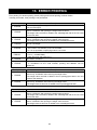
13. ERROR PRINTING ...............................................................................................................................63
14. KEY OPERATION.................................................................................................................................64
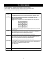
15. TEST MODE .........................................................................................................................................65
16. APPENDIX ............................................................................................................................................66
16-1 External Dimensions/Panel Cutout Dimensions ....................................................................................... 66
AD-8118C...................................................................................................................................................... 66
AD-8118C-10................................................................................................................................................. 66
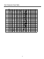
16-2 Character Code Table............................................................................................................................... 67
4
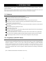
1. INTRODUCTION
The AD-8118C Universal Printer is designed primarily for use with A&D weighing indicators, scales and
electronic balances.
Before using your printer, please read this manual to gain an understanding of its functions and correct use.
After reading, keep this manual at hand so that you can refer to it whenever necessary.
1-1 Features
The AD-8118C Universal Printer has the following features.
Dot impact mechanism allows long-term storage of printed data.
Calendar/clock function. Date and time may be printed.
Cumulative total function and statistical calculation function by code and input channel.
Lithium battery provides cumulative total memory and calendar/clock backup without AC power for
approximately 10 years (with power off).
Serial input is either RS-232C or current loop. Current loop input allows connection to remote devices
(about 100m).
Interval function performs printing at set times
Programmable printing format
Inputs can be expanded up to 4 channels by adding an option board AD-8118C-02 so that the data of
four scales can be printed with one printer.
The same external dimensions, connectors and functions with the AD-8118A/B. Thus, replacement
with an AD-8118C is possible by setting the internal setting contents the same as the AD-8118A/B.
The optional paper winder, AD-8118C-10, allows easier management of the printer paper.
1-2 Compliance with FCC Rules
Please note that this equipment generates, uses and can radiate radio frequency energy. This
equipment has been tested and has been found to comply with the limits of a Class A computing device
pursuant to Subpart J of Part 15 of FCC rules. These rules are designed to provide reasonable
protection against interference when the equipment is operated in a commercial environment. If this unit
is operated in a residential area it may cause some interference and under these circumstances the
user would be required to take, at his own expense, whatever measures are necessary to eliminate the
interference.
(FCC = Federal Communications Commission in the U.S.A.)
5
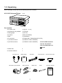
1-3 Unpacking
When unpacking, check that all of the following items are included.
AC-8118C Universal Printer
1 unit
Accessories
• AC power cord
1 (1KO115
• Grounded AC plug adapter
1 (1ET9102)
• Printing paper
1 (1PP137)
• Ink ribbon
1 (ERC-09 EPSON)
• Shaft
1 (105A46423)
• I/O connector
1 (FCN361J024, FCN360C024-B FUJITU)
• 7-pin DIN connector
1 (TCP0576-715267 HOSIDEN)
• 5-pin DIN connector
1 (TCP0556-715267 HOSIDEN)
2.4 m)
Insert the DIN connector
into the “OP-10.OUT”
when the AD-8118C-10 is
not used.
• Rubber feet
4
• Instruction Manual
1
AC power cord
Grounded AC plug adapter
Printing paper
Ink ribbon
DIN connectors
Rubber foot
FCN connector
Shaft
FCN connector case
Instruction manual
7-pin
AD-8118C
5-pin
6
AD-8118C-02 Expansion Input Option Board
• I/O connector
1 (FCN361J024, FCN360C024-B FUJITU)
• Mini DIN connector
3 (TCP6150 HOSIDEN)
Mini DIN connector
FCN connector
FCN connector case
AD-8118C-10 Paper Winder
• Control cable
1 (1KO3228 Approximately 30 cm)
• Connection fixture
2 (M3 pan head screw 2, Hand-tightening screw 2)
• Printer paper cover
1
• Paper guide
1
• Rubber feet
4
Control cable
Note:
Connection fixtures
Printer paper cover
The illustration is not to scale.
7
Paper guide
Rubber foot
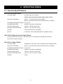
2. SPECIFICATIONS
2-1 General Specifications
AD-8118C Universal Printer
(1) Power supply
85 VAC to 264 VAC, 50/60Hz
Caution: Do not use with a three-phase power source.
(2) Power consumption
Approx. 17 VA with AD-8118C-02 installed
Approx. 20 VA with AD-8118C-02 and AD-8118C-10 installed
(3) Operating temperature range 0°C to 40°C
(4) Operating humidity
80%RH or less (Non-condensing)
(5) External dimensions
192 (W) x 185 (D) x 96 (H) mm
(6) Panel cutout dimensions
186 (+1.0, -0) x 92 (+0.8, -0) mm
(7) Mass
2.4 kg with AD-8118C-02 installed
(8) LCD
16 columns, 2 lines (Character width 2.15 x height 4.35 mm)
AD-8118C-02 Expansion Input Option Board
(1) RS-232C/Current loop (2 to 4 channels (CH), to be switched by rewiring the connector)
(2) Control I/O (Open collector)
AD-8118C-10 Paper Winder
(1) Power supply
Supplied from the printer via the 1KO3228 control cable provided.
(2) Power consumption
Approx. 20 VA with AD-8118C-02 and AD-8118C-10 installed
(3) Operating temperature range 0°C to 40°C
(4) Operating humidity
80%RH or less (Non-condensing)
(5) External dimensions
192 (W) x 185 (D) x 120 (H) mm
(6) Panel cutout dimensions
183 (+1.0, -0) x 115 (+0.8, -0) mm
(7) Mass
2.2 kg
8
2-2 Input Specifications
AD-8118C Universal Printer
(1) Method
RS-232C or current loop (Input selector switch on the real panel)
(2) Baud rate (F1 setting)
RS-232C: 600 bps to 38.2 kbps, Current loop: 600 bps to 2400 bps
(3) Data bits
7/8 bits (Switchable by F2 only for CH1)
(4) Parity bit
1 bit (EVEN)/None (Automatic switch to EVEN when data bits are 7,
and to none when data bits are 8.)
(5) Stop bit
1 bit
(6) Codes used
ASCII or JIS
AD-8118C-02 Expansion Input Option Board
(1) Method
RS-232C or current loop (To be switched by rewiring the connector)
(2) Baud rate (F1 setting)
RS-232C: 600 bps to 38.2 kbps, Current loop: 600 bps to 2400 bps
(3) Data bits
7 bits (fixed)
(4) Parity bit
1 bit EVEN (fixed)
(5) Stop bit
1 bit
(6) Codes used
ASCII or JIS
2-3 Printer Specifications
Printer
(1) Printing system
Dot matrix impact printer
(2) Printing width
24 columns/line for 5x7 dots character (Standard character)
12 columns/line for 10x7 dots character (Enlarged character)
(3) Character size
1.7 (W) x 2.6 (H) mm (Standard character)
3.4 (W) x 2.6 (H) mm (Enlarged character)
(4) Printing speed
Approximately 1.7 lines/second (Internal processing time excluded)
(5) Reliability
Approximately 1,000,000 lines
Ink ribbon
(1) Character color
Black
(2) Life
Approximately 200,000 characters (varies depending on the environment)
To purchase ink ribbons, order using the model number AX-ERC-09-S (5 pieces).
Printer paper
(1) Size
57.5 (W) x 60 (D) mm
(2) Length
Approximately 30 m (A red ending mark appears approximately 1 m before
the end)
(3) Number of printing lines
Approximately 8,000 lines
To purchase printer paper, order using the model number AX-PP137-S (10 rolls).
9
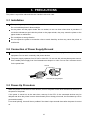
3. PRECAUTIONS
The printer is a precision electronic device. Handle it with much care.
3-1 Installation
The operating temperature range is 0°C to 40°C.
Do not install the printer in direct sunlight.
As the printer and the paper winder are not sealed, do not use them where dust is prevalent. If
conductive substances get inside the printer or the paper winder, they may cause the printer or the
paper winder to malfunction..
Do not subject to strong vibration.
Do not expose the printer to excessive noise or static electricity as that may cause the printer to
malfunction.
3-2 Connection of Power Supply/Ground
Ground the printer to the rear terminal of your scale or balance. Do not plug it in directly to any other
equipment. Do not use it commonly with power devices.
The power supply operates from 85 VAC to 264 VAC. Do not use with a three-phase power source.
Use a stable power supply free from instantaneous dropout or noise. Do not use a common source
for the power lines.
Ground
AC power cord
Grounded AC plug adapter
3-3 Power-Up Procedure
When the printer is connected to other devices, turn on the power of the other devices first, then turn on
the power of the printer.
If the power is turned on at the same time, start-up of the CPU of the connected devices may be
delayed and when the printer is set to the automatic print or dump print mode, the first data may not be
processed normally.
For manual printing, there will be no problem if the data is input several times after the power is turned
on.
10
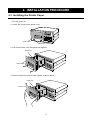
4. INSTALLATION PROCEDURE
4-1 Installing the Printer Paper
1. Turn the power off.
2. Loosen the screws on the printer cover.
Printer cover
Loosen the screws
3. Pull out the printer cover and printer unit together.
Printer unit
Printer cover
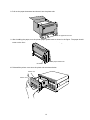
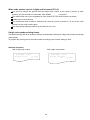
4. Remove the printer cover by lifting it gently as shown below.
Printer unit
Printer cover
11
5. The ink ribbon (
) at the front of the printer unit can be accessed by lifting the printer cover
and removing it from the printer unit.
1
Printer unit
2
Ink ribbon
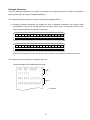
6. Peel off the adhesive tape on the printer paper completely. Insert the shaft supplied as an accessory
into the printer paper and set the paper on top of the printer unit.
Shaft
Ink ribbon
Printer paper feeder knob
7. A top view of the printer unit is shown at the bottom left.
Pass the edge of the printer paper through the slot and pass it under the roller.
Pass the edge of
the printer paper
through this slot.
Pass the edge of
the printer paper
under the white
roller.
Printer paper feeder knob
12
8. Pull out the paper downward and insert it into the printer slot.
Printer paper
Insert the paper into the slot.
9. After installing the paper, turn the printer paper feeder knob as shown in the figure. The paper should
come out the front.
Printer paper feeder knob
Ink ribbon
10. Reinstall the printer cover onto the printer unit as shown below.
Printer unit
Printer cover
13
11. Insert the printer unit into the printer chassis and tighten the printer cover screws.
12. Feed a small amount of printer paper from the printer.
Printer paper
Note: • Do not apply excessive force to the printer unit. If normal, the printer unit can be pulled out
easily. If it is hard to pull out, re-insert it and try to pull it out again.
• The printer is made of electronic circuits and other precision components and could be
damaged if metallic powder, water or other foreign substances get inside it. Also be careful
of static electricity when the printer unit is pulled out.
If dust or other foreign substances get inside the printer, blow it out with clean air. If the
printer is used in a dusty environment, consider using a dust cover or air purge.
• A red ending mark appears approximately 1m before the end of the roll paper; replace the
paper when you see this mark. Printing without any paper in the printer may shorten the life
of the printer.
14
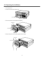
4-2 Replacing the Ink Ribbon
1. Turn the power off.
2. Loosen the screws on the printer cover.
Printer cover
Loosen the screws
3. Pull out the printer cover and printer unit together.
Printer unit
Printer cover
4. Remove the printer cover by lifting it gently as shown below.
Printer unit
Printer cover
15
5. The ink ribbon (
) at the front of the printer unit can be accessed by lifting the printer cover
and removing it from the printer unit.
1
Printer unit
2
Ink ribbon
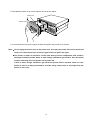
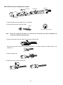
6. Push the PUSH mark at the front left of the ink ribbon while supporting the ink ribbon with your right
hand as shown in the figure. Remove the ink ribbon forward.
Push the
PUSH mark.
Support with the right hand.
7. Install the new ink ribbon by pushing it gently in the arrow direction as shown in the figure.
Ink ribbon
16
8. Reinstall the printer cover onto the printer unit as shown below.
Printer unit
Printer cover
9. Insert the printer unit into the printer chassis and tighten the printer cover screws.
Note: • Do not apply excessive force to the printer unit. If normal, the printer unit can be pulled out
easily. If it is hard to pull out, re-insert it again and try to pull it out again.
• The printer is made of electronic circuits and other precision components and could be
damaged if metallic powder, water or other foreign substances get inside it. Also be careful
of static electricity when the printer unit is pulled out.
If dust or other foreign substances get inside the printer, blow it out with clean air. If the
printer is used in a dusty environment, consider using a dust cover or air purge when the
printer is not in use.
17
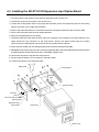
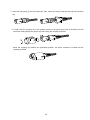
4-3 Installing the AD-8118C-02 Expansion Input Option Board
1. Turn the power of the printer off and remove the power cord from the unit.
2. Loosen the screws on the printer cover to remove it.
3. Loosen the screws (three each on the right and left sides) on the rear panel and pull out the locking
fixtures (one each on the right and left sides).
4. Pull out the main board about 5 cm and disconnect the keyboard cable from the connector CN6.
5. Pull out the rear panel with the main board attached.
6. Remove the blank panel for the option.
7. Install the expansion input option board. Insert the connector CN1 located on the center bottom of the
option board into the connector on the main board. Secure the option board using the screws
removed from the blank panel and the screw that is provided with the printer.
8. Insert the main board into the casing halfway and reconnect the keyboard cable.
9. Reinstall the rear panel using care not to catch the keyboard cable. Insert the locking fixtures and secure the
rear panel with the screws removed in step 3. Reinstall the printer cover.
10. Reconnect the power cord and turn the printer on.
11. Set the internal setting of F19 (number of channels used).
12. Connect the printer to the device(s) used.
6
3
Blank panel
Locking fixture
Connector
CN6
3
4
4
keyboard cable
7
Connector
CN1
5
The screw that is provided
with the printer
Expansion input
option board
Main board
2
Printer cover
18
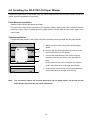
4-4 Installing the AD-8118C-10 Paper Winder
Connect the paper winder to the printer using the control cable provided with the paper winder. Power and
control signal are supplied from the printer.
Panel-Mounted Installation
Install the paper winder right below the printer.
The panel cutout dimensions are shown in the appendix. Make a panel cutout with a sufficient distance
so that the paper winder is placed below the printer and the control cable and the printer paper cover
can be used.
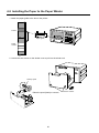
Tabletop Installation
Connect the paper winder to the printer using the connection fixtures provided with the paper winder.
1. Attach the rubber feet to the printer and the paper
2
winder.
2. Remove the side locking brackets (one each on the
4
1
right and left side) from the printer.
3. Connect the paper winder to the printer using the
connection fixtures (one each on the right and left
3
side).
On the paper winder, secure using the four 3M pan
head screws (two each on the right and left side).
4. On the printer, secure using the four hand-tightening
1
Note:
screws (two each on the right and left side).
The connection fixtures are secured temporarily. Do not apply impact. The printer and the
paper winder may dislocate and cause malfunction.
19
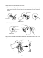
4-5 Installing the Paper to the Paper Winder
1. Attach the paper guide to the slot on the printer.
Printer
Paper guide
Paper
winder
2. Loosen the two screws on the winder cover to pull out the winder unit.
Take-up spool
Raise the spool (black) to remove.
20
Loosen the screws.
3. Wind the paper coming out of the printer onto the spool.
(1) Set the reels according to the paper size.
(2) Fold down the paper edge approximately 1 cm (the lower sheet when using a two-ply paper roll).
Insert it into the slot of the spool until it stops. And then fold the paper at the slot in the winding
direction.
Take-up spool
Reel
Take-up spool
Slot
Paper to be wound
(3) Wind the paper about three turns.
Take-up reel
Fold down.
Paper
Winding direction
4. Set the spool on the winder while holding the center of the paper so that it does not come off the
spool.
Reel
Gear
Frame
21
5. Push the winder unit into the case and secure the winder cover using the two screws.
6. Turn on the power of the printer. The POWER LED of the paper winder will turn on. Feed the paper
several times to check the winder for normal operation. If the winder does not wind the paper properly,
check that the paper is installed in the winder correctly.
4-6 Removing the Paper from the Paper Winder
1. Remove the spool in the same way described in “Installing the Paper to the Paper Winder”.
2. Remove the left side reel.
3. Pull out the paper together with the right side reel.
Reel (Left)
Paper
Reel (Right)
Take-up spool
22
5. DESCRIPTION OF PANELS
5-1 AD-8118C Universal Printer
Front Panel
1
AD-8118 C UNIVERSAL PRINTER
1
Liquid crystal display
16-column 2-line display
7
8
9
4
5
6
1
2
3
0
C
E
2
Operation keys
3
Printer cover
When replacing the printer paper or ink ribbon,
loosen the screws on this cover and pull out the
3
printer unit.
2
Rear Panel
7
1
DATA I/O
AIR PURGE
POWER
ON
OFF
1
POWER switch
2
OP-10. OUT connector
AC 100-240V
This is the paper winder output connector to insert
the control cable provided with the paper winder.
SERIAL IN
CONTROL I/O
C.L.
2
3
When the paper winder is not used, assemble the
RS-232C
4
5
DIN connector provided with the printer and insert
6
it to protect against electrical noise.
3
SERIAL IN connector
This is the RS-232C or current loop input connector.
The channel number is 1.
4
Input selector switch
This control switches the serial input between
RS-232C and current loop.
5
AC power cord connector
6
CONTROL I/O connector
7
Expansion input option board installation area
(Blank panel for an option)
23
Key Operation
Key
[G.TTL]
[S.TTL]
[FEED]
[FUNC]
[PRINT]
[INT.]
[CODE]
[CLOCK]
[SET]
[CAN.]
[END]
[SHIFT]
Description
When the internal setting of F30=1 is selected, pressing this key will
print the grand total value.
When the internal setting of F20=1 is selected, pressing this key will
print the subtotal value.
After printing, the subtotal value is automatically cleared.
Not available for the batch print mode regardless of the F20 setting.
This key is pressed to feed the paper.
This key is pressed to enter various modes such as function setting and
print mode setting in the SET mode.
This key is pressed for manual print mode or printing the list in various
modes.
This key is pressed to enter the interval print mode or UFC mode of
PROGRAM_MODE to set the interval timer of SET_MODE.
This key is pressed to set lot number or code number used for batch
printing, to set code number of SET_MODE, and to enter 6-digit code
number registration mode of PROGRAM_MODE.
This key is pressed to print the date and time, and enter the date and
time setting mode.
When this key is pressed in each print mode, only the current date and
time will be printed.
This key is pressed to enter SET_MODE or exit SET_MODE.
This key is pressed to cancel the input or clear data.
This key is pressed to confirm the settings in SET_MODE or
PROGRAM_MODE.
This key is pressed to switch between SET_MODE and
ROGRAM_MODE, and to switch the input key in print format setting of
PROGRAM_MODE.
[/]
[-]
[*]
These keys are pressed to input settings for print format.
[0] to [9]
These keys are pressed to input numerical values such as code
number and function number.
5-2 AD-8118C-02 Expansion Input Option Board
The Serial input can be expanded by 3 channels and control I/O
2
can be added. The channel numbers from the top are CH2, CH3,
3
4
and CH4.
Option control
I/O connector
The added control I/O functions in combination with the standard
control I/O.
Switching between RS-232C and current loop is by rewiring the
connector.
24
5-3 AD-8118C-10 Paper Winder
Front Panel
AD8118C
1
Winder cover
When installing or removing the printer paper,
OP-10
loosen the two screws on this cover to pull out the
winder unit.
2
Slot
Slot for the printer paper to enter the winder.
3
POWER LED
This LED turns on when the printer turns on.
1
2
3
Rear Panel
1
Connector to the printer
Insert the 1KO3228 control cable to make a
connection between the printer and the paper
winder. Once connected, power and control signal
are supplied from the printer.
2
1
2
25
Side locking bracket for panel-mounted installation
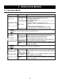
6. OPERATION MODES
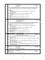
6-1 Operation Modes
Operation mode
Function
Random print
Dump print
PRINT mode
5/20/2007
12:34
Interval print
Batch print
SET
Function
Interval timer
(SET mode)
SET MODE
Code number
F/INT/CODE/CLOCK
Calendar/clock
[END]
Press [FUNC] to set functions.
Press [INT.] to set the timer for interval print function.
Press [CODE] to set code number (F14=3).
F14=3 (Code number setting by key input):
Set code number for each channel, to CH1 through CH4
Press [CLOCK] to set the date and time.
Press [END] to confirm the settings above.
To exit SET_MODE without confirming or changing the
settings, press [SET].
key to switch between SET mode and PROGRAM mode
Printing format
PROGRAM__MODE Code conversion
(PROGRAM mode)
table
(2-digit to 6-digit)
PROGRAM
Print mode to print in F3=1/F9=1 standard format.
Print mode to print in F3=2 dump print mode.
F9 setting is not applicable.
Only available for CH1.
Set F3=1/F9=1.
Press [INT.] to enter the interval print mode.
“INTERVAL PRINT” is displayed in the lower part of the
LCD.
To exit the mode, press [INT.] again.
The printing format is the same as random printing.
Print mode to print in F3=1/F9=2 batch print mode.
key to switch between PRINT mode and SET mode
SET_MODE
SHIFT
Description
MODE
UFC_MODE
F/CODE/INT SHIFT
[END]
Press [FUNC] to set random printing format by key input.
Press [CODE] to set the code conversion table (2-digit to
6-digit).
Press [INT.] to set random printing format by
communications (UFC_MODE).
Press [END] to confirm the settings above.
To exit SET_MODE without confirming or changing the
settings, press [SET].
26
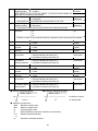
6-2 Mode Selection Procedure
PRINT mode
(When the printer is
turned on)
PROGRAM
SET__MODE
SET
SHIFT
MODE
SET_MODE
When the printer is turned on, it starts up in the PRINT mode.
Then, press [SET] to display
.
SET__MODE
F/INT/CODE/CLOCK
Press [FUNC] (Function) to enter the function setting mode.
Press [INT.] (Interval) to enter the interval timer setting mode.
Press [CODE] to enter the code number setting by key input mode.
Press [CLOCK] to enter the date and time setting mode.
Press [SET] again to exit the SET mode.
PROGRAM_MODE
When
SET__MODE
is displayed,
F/INT/CODE/CLOCK
press [SHIFT] to enter the PROGRAM mode.
PROGRAM__MODE
F/CODE/INT SHIFT
Press [SHIFT] again to return to the SET mode.
Press [FUNC] (Function) to enter the printing format setting mode for random printing and display
[L-
].
Press [CODE] to enter the code conversion table setting mode and display
CODE__2D
6D
Press [INT.] (Interval) to enter communication setting mode (UFC MODE) for random printing format
and display
UFC__MODE
.
WAIT TEXT
27
.
7. PRINT MODES
7-1 Random Print Mode
The random print mode prints the weight data each time the printer receives data from devices connected.
Set the print timing at F-10 (Print timing) for each channel.
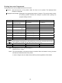
Below is the random printing example (F3=1/F9=1) with the default format (factory setting format).
Standard characters
With 2-digit code number
With 6-digit code number
5/ 2 0/ 2 00 7
12 : 34
1 2. 3 4k g
# 12 3 45 CD 1 2 G
5/ 2 0/ 2 00 7
12 : 3 4
# 12 3 45 CD 1 23 4 56
G
12 . 34 k g
(1) Using the enlarged characters, the number of characters to be printed per line is 12. Program the
printing format in the PROGRAM mode so that the characters are within 12 per line.
(2) With manual printing set (F10=1/2/3), pressing [PRINT] will print the valid data received within 3
seconds and add the data to the internal memory.
If the data is invalid, an error message “F_ERROR” or “I_ERROR“ is printed accordingly.
If no data is received, “T_ERROR“ is printed.
(3) When the option board is installed and multiple channels are used, press [PRINT] to display
CH No. ?
.
Input a channel number (1 to 4) to be printed
(4) When [PRINT] is pressed while holding down [CAN.], “* CANCEL” is printed and the data added last
in memory will be cleared. No other data will be cleared.
(5) With the batch print mode set (F3=1/F9=2), press [PRINT] to display “BACH_MODE” for one second
in the lower part of the LCD.
28
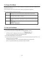
7-2 Dump Print Mode
The dump print mode (F3=2) prints the data as received in the standard format and is available only for
standard serial input (CH1).
For the characters which can be printed, see the Character Code Table in the appendix.
Control codes available for the dump print mode
0DH
Prints the characters up to this input and moves the character point to the
beginning of the next line and resets the enlarged character specification.
0EH
Enlarged characters are printed from the character after this code.
This code is reset by 0DH or 14H input.
14H
If this code is input in the enlarged character mode, the printer returns to the
standard character mode. This command is ignored in the standard character
mode.
This code is used in combination with the following two characters as an
auxiliary code:
1BH+44H Prints the date.
1BH+54H Prints the time.
1BH
*CR (0DH) and LF (0AH) are not printed.
7-3 Interval Print Mode
The interval print mode prints the data at a certain interval.
(1) In the random print mode, press [INTERVAL] to display 5/20/2007
12:34
.
INTERVAL PRINT
“INTERVAL PRINT” is displayed in the lower part of the LCD.
To return to the random print mode, press [INTERVAL] again.
(2) The same setting applies to CH1 through CH4.
(3) In the dump print mode (F3=2), batch print mode (F3=1/F9=2) and manual print mode (F10=1, 2, 3),
interval print mode is not available.
The channels specified at F-10=4, 5, 6 (Automatic printing) perform interval printing.
With F10=5 (Automatic addition only), interval print mode is available
29
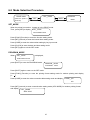
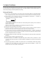
7-4 Batch Print Mode
The batch print mode temporarily stores the input data in a buffer, collects and prints the data in the buffer
for each channel when a batch print command is input. It is mainly suitable for formula weight printing. The
total of batch printing by channel is printed as lot printing.
Setting and Operation
(1) Do not use a connected device in the stream mode as automatic addition is performed internally.
(The F10 setting is ignored). Use the connected device in the automatic print or manual print mode.
(2) Press [CODE] to set an 8-digit lot number. No zero-suppression is performed. If
“01234567” is
input as a lot number, “No.01234567” is printed.
LOT 8D
01234567
The lot number is printed after the date line in batch printing and lot printing. The lot number is
retained unless changed.
8-digit lot number printing is available only in the batch print mode (F3=1/F9=2).
(3) An 80-line buffer is provided for each channel.
(4) The data in the buffer is retained even when the power is turned off. When the power is turned on
again and a batch print command is input from the control I/O, the data is printed.
(5) To clear the data in the buffer, press [PRINT] while holding down [CAN.]. “* CANCEL” is printed and
the data in the buffer is cleared. At this time, the data in the buffer has already been added internally
and the calculated total value is not cleared.
(6) The batch printing is the total for each batch. The lot printing is the total value after several batch
operations.
(7) In the lot printing, the data is cleared after printing.
(8) Subtotal printing is not available in the batch print mode. When [S.TTL] is pressed or a print
command is input from the control I/O, “BATCH_MODE” is displayed for 2 seconds in the lower part
of the LCD.
(9) The grand total printing is possible. The grand total is not automatically cleared after printing.
Pressing [G.TTL] while holding down [CAN.] clears the grand total and displays “* CLEAR”. This
operation does not clear the data for batch printing.
30
Printing Example
Batch printing (printed by a batch print command)(When F9=2)
5 / 2 0 / 2 00 7
12 : 34
N o . 1 2 3 4 56 7 8
1T
<CH1>
CD 1
<CH2>
G
5 5 10 0 kg
CD 2
G
6 .2 1 kg
CD 2
<CH3>
G
8 .1 7 kg
Batch number
Incremented for each batch and serves as a serial number.
No. 12345678 is an 8-digit lot number and is input from the
keys.
<CH4>
- - - - - - - -- - - - - - - -- - -- - -5 5 11 4 .3 8 kg
Lot printing (Printed by a lot print command)
LOT
TOTAL
12 : 34
N o. 1 23 4 56 78
1T
< CH 1 >
CD 1
G
5 5 10 0 kg
< CH 2 >
CD 2
G
1 4 .3 8 kg
< CH 3 >
< CH 4 >
- -- - -- - -- -- - -- - -- - -- - -5 5 11 4 .3 8 kg
5/ 2 0/ 2 00 7
This is an example of lot printing after the batch printing
above was performed one time.
31
8. SET_MODE
8-1 Setting the Functions
Function setting procedure
(1) Press [FUNC] to enter the function setting mode.
is displayed.
F-
(2) Using the numerical keys [0] to [9], input the function number to be set, press [END] to confirm it
and display the function data.
F- 1
3
2400bps
(3) Press [*] or [↓] to change the function data.
(4) Press [END] to confirm the change and move to the next function data.
(5) Press [PRINT] to print the function list.
(6) Press [SET] to exit the function setting mode.
(7) The function that is to be specified for each channel is indicated by a 4-digit number.
Below is an example of F-10 (Print timing).
F-10 333 3
CH1
Manual add print
The default value is 3333.
Each digit corresponds to a channel, from CH1 through
CH4: [3333 CH1], [3333 CH2], [3333 CH3], [3333 CH4]
Press [*] or [↓] to set the function and press [END] to conform the setting. The cursor moves to the
left digit. Set the function for each channel.
*
32
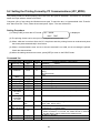
Function List
No.
F- 1
Function
Baud rate
(CH1 to CH4)
Description
RS-232C
Current loop
F- 4
•If the data cable is long or transmission errors may occur, set the baud rate to slower
values..
1: 7 bits/EVEN
1
Data bits
2: 8 bits/None
(7 bits)
(Only for CH1)
•The number of data bits can be selected to be 7 bits or 8 bits for CH1 only.
•For CH2 to CH4, the number of data bits is fixed at 7 bits even parity.
•For 7 bits, the parity is 1 even and for 8 bits, there is no parity bit.
Input signal mode 1: Standard format
1
(Standard format)
(Only for CH1)
2: Dump print mode*
1: Standard format
•Prints the number, weight data, etc. according to the data received from the device
connected and sum those data.
2: Dump print mode
•Prints the data as received.
•Totaling and printing format program functions can not be used.
•The dump print mode is only for CH1 (standard serial input).
•Starts to print when CR or CR, LF is received, or the number of characters exceeds
26.
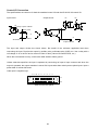
Printing mode
1: Normal characters
1
2: Inverted characters
(Normal characters)
Available to all of the printing operations (Random printing, batch printing, dump mode
printing, subtotal, grand total).
1: Normal characters (Random printing)
During printing, normal characters are output in the reverse direction, but are printed
in the forward direction
61. 0 0kg
F- 3
Default value
3
(2400 bps)
M o nt h D a y Ye a r Hou r Mi n u t e
F- 2
1: 600 bps
2: 1200 bps
3: 2400 bps
4: 4800 bps
5: 9600 bps
6: 19.2 kbps
7: 38.4 kbps
1: 600 bps
2: 1200 bps
3: 2400 bps
2: Inverted characters (Random printing)
During printing, inverted characters are output in the forward direction, but are printed
in the reverse direction.
M o n th D a y Yea r H ou r Mi n ut e
61.00 kg
33
F- 5
F- 6
Input conditions
0: No (Not received)
1: Yes (Received)
1
(Yes)
0: No
Negative or unstable weight data are regarded as invalid and are not printed.
1: Yes
Even negative or unstable weight data are regarded as valid and are printed.
Character size
1: Standard character (5x7 dots)
1
(Standard
2: Enlarged character (10x7 dots)
character)
The number of columns/line is 24 for the standard size and 12 for the enlarged size.
F- 7
key input
F- 8
Number of paper
0 to 9
2
feed lines
Sets the number of paper feed lines after each time printing and cumulative total
printing.
Print mode
1: Random print mode
1
2: Batch print mode
(Random print)
F- 9
0: Disabled
1: Enabled
Enables key inputs or disables key inputs other than [SET].
1
(Enabled)
1: Random print mode
•The random print mode prints the input data in the format set at F10 and perform
subtotal and grand total functions.
•When the print timing is set to addition only, printing the input data is not performed.
(When F10 is set to 2 or 5.)
2: Batch print mode
•In the batch print mode, the input data is temporarily stored in a buffer and the data in
the buffer is printed for each channel when a batch print command is input.
•An 80-line buffer is provided for each channel.
•The printing format is fixed.
F-10 Print timing
1: Manual printing
3
2: Manual addition
(Manual
3: Manual addition printing
addition
4: Automatic printing
printing)
5: Automatic addition
6: Automatic addition printing
Only available for standard format (F3=1/F9=1).
Manual
Manual printing processes the first valid data that is input within 3 seconds after a print
command is input from [PRINT] or the control I/O. Set the data output of the connected
device to the STREAM mode.
1: Manual printing: Only printing is performed at the print command input.
2: Manual addition: Only addition is performed at the print command input.
3: Manual addition printing: Printing and addition are performed at the print command
input.
Automatic
Automatic printing processes all the input valid data. Set the data output of the connected
device to the automatic print or the manual print mode
4: Automatic printing: Only printing is performed at data input.
5: Automatic addition: Only addition is performed at data input.
6: Automatic addition printing: Printing and addition are performed at data input..
34
F-11
F-12
F-13
F-14
F-15
Input data selection 1: All enabled
1
2: Gross weight
(All
3: Net weight
enabled)
4: Tare
This function setting is used when connecting an indicator and multiple peripheral
devices. Mainly the indicator is set to the mode to transmit all of Gross/Net/Tare
(G/N/T).
1: All enabled
When G/N/T are printed at once, set the printing format accordingly in the
PROGRAM mode.
Also for data format of other devices such as a balance or scale.
2: Gross weight
Enables the data when the second header is “GS” or “G_”.
3: Net weight
Enables the data when the second header is “NT” or “N_”.
4: Tare
Enables the data when the second header is “TR” or “R_”.
Calculation data
1: Total all
1
2: Total gloss weight only
(Total all)
3: Total net weight only
4: Total tare only
This function setting is used when connecting an indicator and multiple peripheral
devices. Mainly the indicator is set to the mode to transmit all of G/N/T.
1: Total all
When G/N/T are printed at once, set the printing format accordingly in the
PROGRAM mode.
Also for data format of other devices such as a balance or scale.
2: Total gross weight only
Enables the data when the second header is “GS” or “G_”.
3: Total net weight only
Enables the data when the second header is “NT” or “N_”.
4: Total tare only
Enables the data when the second header is “TR” or “R_”.
Key input code No.
(Number of digits)
1: 2-digit code number
1
2: 6-digit code number
(2-digit)
3: 6-digit code number and increment
This function selects whether the code No. is handled as 2 digits or 6 digits.
1: 2-digit code number
The input method is set at F14. A code number is converted to six digits by selecting
F15=1.
2: 6-digit code number
When the code number is set to 6 digits, all input is from the keys. (F14 and F15
settings are ignored.)
3: 6-digit code number and increment
When the code number is set to 6 digits, all input is from the keys. (F14 and F15
settings are ignored.)
The code number is incremented by one at each printing.
Code number input 1: Control I/O
3
method
2: Serial input
(Key input)
3: Key input
Available when F13=1 (2-digit code number).
Converts code
0: Not converted
number from 2
1: Converted
digits to 6 digits.
Available when F13=1 (2-digit code number).
35
0
(Not
converted
F-16
F-17
F-18
F-19
Polarity and
0: Not printed
1
header printing
1: Printed
(Printed)
Sets whether or not to print the polarity (-) and the second header (G: gross, N: net,
tare) that is formatted by the indicator.
Time display
0: Not displayed
1
1: Displayed
(Displayed)
Sets whether or not to display the date and time in THE LCD.
Time printing at
1: First time
2
random printing
2: Each time
(Each time)
Sets when the date and time are printed in the random print mode.
Number of input
1: 1
1
channels
2: 2
(1)
3: 3
4: 4
Sets the number of input channels when the expansion input option board is installed.
F-20
Subtotal
F-21
Subtotal by code
number
Subtotal by
channel
Printing Statistics
by channel
F-22
F-23
F-24
Printing
cumulative
subtotal statistics
F-30
Grand total
F-31
Grand total by code
number
Grand total by
channel
Printing Statistics
by channel
F-32
F-33
F-34
Printing
cumulative grand
total statistics
0: Not used
1: Used
0: Not used
1: Used
0: Not used
1: Used
0: Not used
1: Sample standard deviation (N-1)
2: Population standard deviation (N)
0: Not used
1: Sample standard deviation (N-1)
2: Population standard deviation (N)
1
(Used)
1
(Used)
1
(Used)
0
(Not used)
0: Not used
1: Used
0: Not used
1: Used
0: Not used
1: Used
0: Not used
1: Sample standard deviation (N-1)
2: Population standard deviation (N)
0: Not used
1: Sample standard deviation (N-1)
2: Population standard deviation (N)
1
(Used)
1
(Used)
1
(Used)
0
(Not used)
● Sample standard deviation
0
(Not used)
●Population standard deviation
NΣXi2 –(ΣXi2)
σn-1
NΣXi2 –(ΣXi2)
σn
N:Number of times
N2
N(N-1)
● Statistics printing items
MAX
MIN
X
R
σn-1
or
σn
0
(Not used)
:Maximum weight value
:Minimum weight value
:Average weight value
:Range (Difference between maximum and minimum)
:Sample standard deviation
:Population standard deviation
36
Xi:Weight data
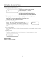
8-2 Setting the Interval Timer
Interval timer Setting Procedure
(1) Press [INT.] to enter the interval setting mode.
S
: * * :**
P
*:** :**
is displayed. The default value is 10 seconds.
“S”: Non-printing time, “T”: Print time
The digit at the left end represents the hour.
The 2 digits at the center represent the minute.
The 2 digits at the right end represent the second.
(2) Set the numbers in accordance with movement of the cursor from left to right.
Press [END] to proceed to the next digit, and [SHIFT] to return to the previous digit.
Press [SET] to confirm the setting and return to the PRINT mode.
The setting is the same for channels 1 through 4.
(3) “S” sets the non-printing time.
0 (zero) can not be selected for non-printing time. If 0 is
TIME_ERROR
selected, an error message “TIME_ERROR” is displayed for 1
second and the printer returns to the non-printing time setting
mode.
(4) “P” sets the print time.
When the print time is set to 0:00:00, the first data sent after the non-printing time elapsed is printed
one time.
(5) Setting example
To print the data at an interval of 1 hour 10 minutes and 12 seconds, set as shown below.
S 1 :1 0 :1 2
P 0 :0 0 :0 0
Interval Printing
Refer to “7-3 Interval Print Mode”.
37
8-3 Setting the Code Number
Code number is the number which is paired with the weight data. Three types of code number input are
available in F13.
When code number input is 2 digits (F13=1)
The code number can be input for each material and product name and the total of each can be printed.
(1) The code number can be registered for each channel (CH1 to CH4).
Press [CODE] to enter the code number setting mode.
CH1 * *
CH2 * *
is displayed.
CH3 * *
CH4 * *
The 2 digits at the right represent the code number.
Input a number for each digit. For example, to input a code
number of 1, press the key as follows: [0] [END] [1] [END]
Press [END] to confirm the setting and proceed to the next digit.
Press [SHIFT] to return to the previous digit.
Press [SET] to return to the PRINT mode.
(2) Totaling for each code number can be performed.
(3) When F15=1, the code number that is set in the PROGRAM mode is printed and the total of each
can be printed.
For PROGRAM_MODE code conversion table setting procedure, refer to “9-3 Setting the Code
Conversion Table “
When code number input is 6 digits (F13=2)
This is convenient when separating print data by lot and when referencing each print data.
F14 and F15 settings are ignored and the 6-digit code number by key input is printed.
The code number can not be registered for each channel. It is the same for all the channels.
Totaling for each code number cannot be performed.
Code number setting procedure
(1) Press [CODE] to enter the code number setting mode.
CODE 6D
* ** **
is displayed.
Press [END] to confirm the setting, and [CAN.] to return to the previous digit.
Press [SET] to return to the PRINT mode.
38
When code number input is 6 digits and increment (F13=3)
F14 and F15 settings are ignored and the 6-digit code number by key input is printed. At each
printing, the code number is incremented. After 999999, _ _ _ _ _ 1 is printed.
The code number can not be registered for each channel. It is the same for all the channels.
Totaling cannot be performed
The incremented code number is retained even when the power is turned off. To use a new code
number, set the code number again.
The code number setting procedure is the same as for F13=2.
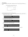
6-digit code number printing format
The default printing format for random printing is automatically switched for 2-digit code number and 6-digit
code number.
To program the printing format, the code number according to the function setting is used.
Standard characters
With 2-digit code number
With 6-digit code number
5/ 2 0/ 2 0 0 7
12 : 3 4
1 2. 3 4k g
# 12 3 45 C D 1 2 G
5/ 2 0/ 2 00 7
12 : 3 4
# 12 3 45 CD 1 23 4 56
G
39
12 . 34 k g
8-4 Setting the Date and Time
The date is displayed in two ways:
USA:
MM/DD/YYYY (e.g. 12/31/2007)
Europe: DD/MM/YYYY (e.g. 31/12/2007)
The time is in 24-hour system.
Date and Time Setting Procedure
(1) Press [CLOCK] to enter the date and time setting mode.
20 7/05/20/
12:34
is displayed.
Press [END] to move the cursor one column to the right.
(2) Set the year by inputting the last 2 digits.
(3) Set the date. For example, to set May for the month, input as follows: [0] [END] [5] [END].
(4) Set the time in 24-hour system.
(5) After setting, press [SET] to confirm the setting and return to the PRINT mode.
40
9. PROGRAM_MODE
9-1 Setting the Printing Format
The random printing/interval printing format of nine lines is programmed by key input. The default setting is
the standard format. To change the setting, clear one line or all lines of the program data.
To enter the PROGRAM mode, first enter the SET mode by pressing [SET] in the PRINT mode, and then
press [SHIFT].
Printing Format Setting Procedure
(1) In the PROGRAM mode, press [FUNC].
Line
is displayed.
Input the line number and press [END] to display the setting contents with the cursor on the first
character.
Press [END] to move to the next line.
Press [SET] to confirm the setting.
Press [CAN.] to clear all the printing data set for the line.
To change the setting, press [CAN.] to clear the setting and then input a new setting.
(2) To clear all lines of the program data.
When Line
is displayed, press [SHIFT].
Line
ALL Clear
is displayed.
Press [CAN.] to clear all lines of the program data and return to the previous display.
Press [1] to set the default printing format and print the dummy data.
Press [2] to set the date, time, number of times, gross weight, net weight, tare in the printing
format.
Program outline
123 ・ ・ ・ ・
24
( Line 1)
( Line 2)
( Line 3)
( Line 4)
( Line 5)
: :
( Line 9
41
Printing Items to be Programmed
Printing items that can be programmed are shown below.
Item No.: Input the item No. in the position where the item is to be printed. The displayed data
example is displayed.
Displayed data example: Displayed in the appropriate number of columns. This can be used to check
the printing position because the example is printed when printing the
program setting contents.
Item No.
0
1
2
Item
Day month year
Month day year
Hour minute
Channel No.
3
Code No.
Displayed data example
Number of columns
00/00/2000
11 columns
11:11:
CH2
6 columns(24-hour system)
3 columns
4
CD333333
(Note 1) CD33
Number of times
#44444
8 columns
4 columns
6 columns
5
Gross weight
(Note 2) G_ _ 5555555kg
12 columns
6
Net weight
(Note 2) N_ _ 6666666kg
12 columns
7
Tare
(Note 2) T_ _ 7777777kg
12 columns
8
9
Weight value
Space
SHIFT
88888888888g
_
12 columns
1 column
While setting the printing items, press [SHIFT] to set the three characters shown below.
When [SHIFT] is pressed, the right side of the Line No. turns on.
*
*
1 column
1 column
/
/
1 column
Asterisk
Hyphen
Slash
Note 1: CD333333 for F13-1, F15-1 or F12=2, 3
CD33 for F13-1, F15=0
Note 2: The second header of the data received is checked. When the header is wrong, the data
will become invalid and will not be printed.
In case of weight value, the data received will be printed regardless of the header.
42
Displaying the Setting Contents
In the PROGRAM mode, the contents that are currently set are displayed.
Turns on when [SHIFT] is pressed
Line No. inputting position
L
i
n
0
0
L
i
n
D
3
3
e
1
1
e
Input starting position for Line 1
1
:
1
2
8
8
8
8
0
0
/
0
0
/
1
:
#
4
4
4
4
4
8
8
8
8
8
8
2
0
Input ending position
for Line 1
(24th column)
C
8
g
Press [PRINT] to print the dummy data in the program printing format.
Printing example of the default program printing format
0 0/ 0 0/ 2 00 0 _ 1 1 : 11 :
# 44 4 44 _ CD 3 3_ 8 8 8 88 8 88 8 88 g
_ = 9: Space
Note: • The maximum number of columns for one line is 24. When it exceeds 24, the item input last
is not accepted.
• When printing items are not set, pressing [SET] does not function and does not exit the
setting mode. When all lines of the program data are cleared, be sure to set the printing
items.
43
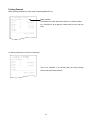
Setting Example
In the below example, the gross weight, net weight and tare data are received from the indicator and
printed.
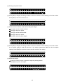
Printing example of the printing format to be set
5/ 2 0/ 2 00 7
1 1 : 11
# 12 3 45 CD 1 2 G
1 2. 0 5k g
N
1 0. 0 5k g
T
2. 0 Ok g
The setting is performed while clearing the contents by the line.
(1) In the setting mode, input “1” for Line to display the setting contents for the line 1 with the cursor
blinking on the first column of the setting.
L
i
0
0
n
e
1
1
1
:
1
2
0
1
:
/
0
0
/
2
0
0
0
/
2
0
(2) Press [CAN.] to clear the setting contents.
L
i
n
e
1
(3) Set the date and time. Press [0] to input the date.
L
i
0
0
n
e
1
0
0
/
(4) After the date, a space is required. Press [9] to move the cursor one column to the right.
L
i
0
0
n
e
1
0
0
/
44
0
0
/
2
0
(5) Press [1] to input the time.
L
i
0
0
n
e
1
1
1
:
1
0
0
1
:
/
0
0
/
2
0
(6) Press [END] to display the setting contents for the line 2 with the cursor blinking on the line number.
Press [END] to move the cursor on “#”.
L
i
n
D
3
3
e
2
8
8
8
8
#
4
4
4
4
4
8
8
8
8
8
8
C
8
g
(7) Set the number of times, code number and gross weight.
Press [4] to set the number of times.
Press [9] to input one space.
Press [3] to set the code number.
Press [9] to input one space.
Press [5] to input the gross weight.
L
i
n
D
3
3
e
2
G
5
#
4
4
4
4
4
5
5
5
5
5
5
C
K
g
(8) Press [END] to display the setting contents for the line 3 with the cursor blinking on the line number.
As no default setting is made for the line 3, the setting contents are blank and do not require
clearing. Press [END] to move the cursor to the first column of the setting.
L
i
n
e
3
(9) Set the net weight.
Press [9] 12 times to input 12 spaces to align the printing position.
Press [6] to input the net weight.
L
i
n
e
3
N
6
6
6
6
45
6
6
6
K
g
(10) Press [END] to display line 4 with the cursor blinking on the line number. Press [END] to move the
cursor to the first column of the setting.
L
i
n
e
4
(11) Set the tare.
Press [9] 12 times to input 12 spaces to align the printing position.
Press [7] to input the tare.
L
i
n
e
4
T
7
7
7
7
7
7
7
K
g
(12) Press [END] to display line 5 with the cursor blinking on the line number.
(13) Press [PRINT] to print the dummy data in the program printing format. Check the printing position
and printing items.
Printing example of the set printing format
0 0/ 0 0/ 2 00 0
1 1 : 11
# 44 4 44 CD 3 3 G
55 5 5 5 5 5 K g
N
66 6 6 6 6 6 K g
T
77 7 7 7 7 7 K g
(14) When the printing position and printing items are all right, press [SET] to return to the PRINT mode.
46
Enlarged Characters
Using the enlarged characters, the number of characters to be printed per line is 12 while 24 characters
can be printed per line using the standard characters.
The setting procedure is the same as the printing format setting procedure.
(1) Because enlarged characters are double the size of standard characters, the printing format
programmed on one line is actually printed on two lines. That is, line 1 sets the items for line 1 (the
first 12 columns) and line 2 (the last 12 columns).
L
i
n
e
1
1
2
3
4
5
6
7
8
1
1
2
3
4
5
6
7
8
9 10 11 12
L
i
n
e
9 10 11 12 13 14 15 16 17 18 19 20 21 22 23 24
The line 2 sets the items for line 3 and line 4 and up to line 9, the maximum 18 lines can be set.
The setting contents are printed in characters set in F6.
Printing example of the default printing format
00/00/2000 _
Line 1
11:11:
#44444_CD33_
Line 2
88888888888g
_ = 9: Space
47
9-2 Setting the Printing Format by PC Communications (UFC_MODE)
The printing format for random printing can be set in the text (with an extension, .txt) from a PC. To use this,
switch the input selector switch to RS-232C.
Compose a line of text using the Windows memo pad. To send the text: In Hyperterminal click “Transfer”
and “Send Text File”. Then, select the text and press “Open”. The text will be sent.
Setting Procedure
(1) Press [FUNC] to enter the UFC mode. UFC MODE
is displayed.
WAIT TEXT
(2) The printing format can be set upon receiving the text from the PC.
(3) When valid text is received from the PC, the printer sets the printing format as received and prints
the dummy data automatically in that format.
(4) When a communications error occurs or the text received is not valid, an error message is printed.
Check the data received.
(5) When the setting contents are correct, press [SET] to return to the PRINT mode.
Command list
Printing data
Command Columns
Printing example / Description
11
12/23/2007_ _: Space
1 Month day year
$DT
6
10:13_ _: Space
2 Hour minute
$TM
CH2
Channel
No.
3
$CH
3
2-digit or 6-digit is automatically recognized by the function
Code No.
4
$CD
8
5
6
7
8
9
10
11
12
13
14
15
16
17
Number of
$NO
times
Gross weight
$GR
Net weight
$NT
Tare
$TR
Weight
$WW
Space (_)
$SP
Enlarged
$ON
characters
used
Enlarged
$OF
characters
not used
ANK characters Enclosed
with ’ ’
Other than
#**
ANK characters
Initialization
CL
CR
LF
$CR
$LF
5
setting.
CD12/CD123456
#1234
12
12
12
12
1
--
G_+1234567kg (unit received)
N_+1234567kg
T_+1234567kg
+1234567890g (weight value and unit received)
Space
Data set after this command is printed by enlarged characters.
--
Data set after this command is printed by standard characters.
--
Specify the data enclosed using ’and ’.
(ASCII code 20H to 7FH)
Characters other than ANK characters that can be used are
specified as #** (**=ASCII code).
Restores the printing format to the default settings.
When CL$CR$LF is received, the default format is restored
and the dummy data is printed in the default format.
CR (Return) (0D Hex)
LF (Line feed) (0A Hex)
--
--
--
--
48
Printing Format in Text
The printing format can be set in the text (with an extension, .txt) made by using PC memo pad. Specify
the number of characters to be printed according to the setting of F6.
Standard characters
Example text
Printing example of the dummy data
PF1, ’A&D co.Ltd’$CR$LF
PF2,
$DT$CR$LF
PF3,
$SP$CR$LF
PF4,
$SP$GR$CR$LF
A &D co . Lt d
0 0/ 0 0/ 2 00 0
_ G 5 55 5 55 K g
(1) PF1, ‘A&D co. Ltd’ $CR$LF
PF1: Specifies line 1. Then, specify the characters to be printed. At the end of line 1, specify
$CR$LF and press [ENTER] to change lines.
(2) PF2, $DT$CR$LF
PF2: Specifies line 2. $DT: Specifies to print the date
(3) PF3, $SP$CR$LF
PF3: Specifies line 3. $SP$CR$LF: Specifies one blank line.
(4) PF4, $SP$GR$CR$LF
PF4: Specifies line 4. $SP: Specifies one space. $GR: Specifies the gross weight.
(5) The lines to be specified are from PF1 to PF9. Specify in order starting with PF1. Otherwise the error
message “F_ERROR” is displayed. To have one blank line, write $SP$CR$LF after specifying the
line.
Enlarged characters
(1) The number of characters per line is 12. Specify the items to be printed accordingly.
(2) The lines to be specifies are from PF1 to PF9.
49
Error Messages
An error message is displayed when the text received is not valid.
Error message
1
F_ERROR
2
3
4
Description
The number of characters per line is exceeded.
PF1 is not specified or specifying order is not correct.
L_ERROR The number of lines exceeded 9.
C_ERROR An invalid command is received.
M_ERROR Characters that the printer can not print are received.
Communications Cable
AD8118C
PC
RS-232C
RS-232C
3
2
5
5
8
7
The printer is to be connected via RS-232C. Set the input selector switch to RS-232C.
50
9-3 Setting the Code Conversion Table
Setting Procedure
(1) Press [CODE] to enter the code conversion table setting mode.
CODE 2D
2-digit code number “01” and 6-digit code number to be
1
converted are displayed.
6D * * * * * *
99 code number from 01 to 99 can be registered.
Press [END] to confirm the setting.
Press [CAN.] to clear the setting and to return to the previous setting.
When F13=1 (2-digit code number), F15=1 is enabled regardless of F14 setting.
(2) Input the 2-digit code number. For example, to input “06”, input [0] [6] and [END]. The input is
confirmed and the cursor moves to the lower line of the 6-digit code number.
(3) The current 6-digit code number or “6D
0” when the 6-digit code number is not registered is
displayed. Input the 6-digit code number. For example, to input “123”, input [1] [2] [3] and [END].
(4) When [END] is pressed, the setting is confirmed and the next 2-digit code number is displayed.
(5) Press [PRINT] to print the list of conversion table registered.
CO D E L I S T
CD 0 1
CD 0 2
123
222
CD 1 0
1 2 34 5 6
Recalling the Conversion Table
In random printing with F13=1, to convert the code number to 6-digit, read the conversion table to recall
and print the 6-digit code number registered to the 2-digit code number.
This operation is available regardless of F14 setting.
When the 6-digit code number is not registered, “0” is printed.
51
10. SERIAL INPUT / CONTROL I/O
10-1 Serial Input Connection
Standard Serial Input (CH1 only)
The standard serial input can be switched between RS-232C and current loop by the input selector switch
on the real panel. Select either one depending on the product being connected.
Connection table
Pin No.
Symbol
1
C.L.OUT
2
F.G.
3
Ser.IN+
4
GND
5
Ser.IN6
I.C.
7
I.C.
Description
Current loop output
Frame ground
Serial input + (TxD)
Signal ground
Serial input- (SG)
Connected internally
Connected internally
6
7
1
3
4
5
2
View from the rear panel
Serial input uses both RS-232C and current loop. For RS-232C, pin 5 is signal ground. Connect
the shield to pin 2.
Shielded twisted pair cable is recommended as the signal line.
External display
Current loop
Input
Current loop
Output
1
C.L.
2
3
RS-232C
4
5
Shield
Input
Scales, balances
Current loop
/RS-232C
6
7
AD-8118C
Note:
Standard serial input CH1 of the printer has a function which outputs the serial input
directly by current loop. Devices such as a display can be connected by means of this.
Even if the RS-232C input is used, output is by current loop.
52
AD-8118C-02 Expansion Serial Input (CH2, CH3, CH4)
Switching between RS-232C and current loop can be performed by rewiring the connector.
Current loop output is not available for expansion serial input.
Connection table
Pin No.
Symbol
1
CONV.OUT
2
F.G.
3
C.L. IN
4
RS IN
5
S.G.
Description
RS-232C conversion output
Frame ground
Current loop input
RS-232C input
Signal ground
5
3
4
2
1
View from the rear panel
Interface circuit (common to all channels)
1
2
C.L.
3
4
5
AD-8118C
Current loop connection
RS-232C connection
CONV.out 1
1
FG
2
Sig+ 3
Current loop
3
4
SG
AD-8118C
5
4
FG
2
CLin
3
RS-232C in 4
4
5
5
SG.
AD-8118C
53
RS-232C
Mini DIN Connector Assembly Procedure
(G) Cap
(E) Spacer
(H) Cover
(B) Frame
(D) Connector
(C) Clamper
(F) Coil spring
(A) Coupling
1. Insert the parts onto the cable in (G), (F), (E) order.
2. Connect the connector (D) to the cable.
Cable
4
2
1
5
3
Front of the connector (D)
Note:
Check the wiring at the time it is wired to the connector (D). Once assembled, the
connector cannot be disassembled.
4. Insert the connector with the cable connected into the frame (B).
When the connector reaches the prescribed position, it is locked. Clamp the cable shield by the
clamper (C).
5. Insert the spacer (E).
6. Place the cover (H) on the frame (B).
54
7. Insert the coil spring (F) into the frame (B). Then, insert the cap (G) onto the frame (B) and lock the
cap.
8. Finally, hold the coupling (A) in the position shown in the figure and insert it forcefully onto the
connector while grasping the spacer (E) and turning the coupling clockwise.
When the coupling (A) reaches the prescribed position, the entire connector is locked and the
coupling (A) slides.
55
10-2 Control I/O Connection
Standard Control I/O
A Control I/O is provided to the AD-8118C Universal Printer (standard) and AD-8118C-02 Expansion Input
Option Board (option). Please note that the signal contents are different when the number of input
channels in F19 setting is less than three and three or more. When an option board is not installed, the
signal contents for less than 3 are applied.
Pin No.
A1
2
3
4
5
6
7
8
9
10
11
12
B1
2
3
4
5
6
7
8
9
10
11
12
Less than 3
Contents
1
2
4
8
10
20
40
80
CH1 Code input
3 or more
Contents
1
2
4
8
10
CH4
CH3
CH2
CH1 print command input
Paper feed command input
Subtotal print command input
Grand total print command input
Grand total clear command input
Interval print ON
Batch print command input
Lot print command input
Busy output
Print announcement output
NC
Output COM
NC
Input COM
Input COM
F.G.
56
CH1 Code input
Print command input
Print command input
Print command input
Common
AD-8118C-02 Control I/O
Less than 3
Pin No.
Contents
A1
1
2
2
3
4
4
8
CH2 Code input
5
10
6
20
7
40
8
80
9
CH2 Print command
10
(*Note)
11
(*Note)
12
(*Note)
B1
(*Note)
2
(*Note)
3
(*Note)
4
(*Note)
5
CH2 Busy output
6
CH3 Busy output
7
CH4 Busy output
8
Output COM
9
NC
10
Input COM
11
Input COM
12
F.G.
(*Note) Not to be connected
3 or more
Contents
1
2
4
8
10
1
2
4
8
10
1
2
4
8
10
57
CH2 Code input
CH3 Code input
CH4 Code input
Control I/O Connection
The specifications are common for both the standard control I/O and the AD-8118C-02 control I/O.
Input circuit
Output circuit
+V
+V
+V
Relay or open collector
Approx. 5mA
or
or
Input common
AD-8118C
Output common
The input and output circuits are shown above. Be careful of the minimum applicable load when
connecting the input. Receive the output by auxiliary relay, solid-state relay (SSR), etc. Use a relay with a
coil voltage of 12 to 24VDC and a current of 50mA or less. (Omron MY Series DC24, etc.)
When the environment is noisy, connect the cable shield to frame ground.
Unless otherwise specified, the input is operated by connecting an input to input common and when the
output is operated, the output transistor is turned ON. Inputs other than code input are pulse inputs. Input a
pulse width of at least 200 msec.
Code input is negative logic.
12 11 10 9 8 7 6 5 4 3 2 1
A
B
View from the rear panel
58
Control I/O Operation
Input
Code input
When F14 is set to 1, the code No. input from the control I/O becomes valid.
When two or less channels are connected, the code No. can be input in 2
digits. When three or more channels are connected, the code numbers that
can be used are 0 to 19.
Print command*
When this input is turned ON, the first data that enters within the next three
seconds is printed or added. However, this applies only when the F10 print
timing is set to manual.
Paper feed command
Feeds the paper by one line.
Subtotal print command Prints the subtotal up to that command point. After printing, the subtotal value is
not stored, but is cleared. This command cannot be used in the batch print mode.
Grand total print
Prints the grand total up to that command point. After printing, the
cumulative total values (subtotal, grand total) are not cleared.
Total clear
Clears the total (subtotal and grand total) value up to that command point.
“*CLEAR” is printed.
Interval print command When this input is turned ON, interval printing is performed. I/O has priority
over key input.
Batch print command
With F9 set to 2 (batch printing), when this signal is turned ON, batch
printing is performed.
Lot printing command
With F9 set to 2 (batch printing), when this signal is turned ON, lot printing
(batch printing total) is performed.
Inputs indicated by the * do not operate at automatic printing. At dump printing, inputs other than paper
feed do not operate.
Output
Busy
When the data buffer exceeds 75 lines, this output is turned ON.
Print announcement
When the printing operation is performed, this signal is turned ON. At this time, control
inputs are not received. Therefore; input control inputs, when this output is off.
Timing Chart
CH1 printing
CH2 printing
Printing announcement
output
CH1 Print command
CH2
CH3
CH4
59
CH4 printing
CH3 printing
Always input the control signals when the print announcement output is off or set the printer to the
automatic print mode (F10=4 or 6) and input a print command to an indicator set to the manual print
mode.
Each command input is judged by edge and is operated only once when it is turned ON.
When an input is turned ON (connected to input common) for more than 200ms, it is accepted.
The print announcement output is not necessarily turned ON only during the printing operation.
At manual printing, serial data is not input within three seconds after a print command is input, the
print announcement output is turned ON for three seconds after the print command input.
Timing Chart
Printing announcement
output
Print command
Serial data
Printing operation
11. DATA BUFFER
The printer has a data buffer for 80 data so that data can be input even while the printer is printing.
When data temporarily overlaps and the printing speed is exceeded, the data is stored in this buffer. When
printed, that data is cleared.
When this buffer exceeds 75 lines, the I/O output busy signal is turned ON and when it exceeds 80 lines,
“B_ERROR” is printed one time.
When the buffer drops to 75 lines or less during printing, when it exceeds 80 lines again, “B_ERROR” is
printed again.
Since the printing speed is approximately 1.7 lines/second (the printing speed of one data is for the
number of lines including the time printed and the lines fed), do not input data at a speed exceeding this.
When the power is turned off before the data contents stored in the data buffer are printed, the data
contents are cleared.
60
12. PRINTING SAMPLES
12-1 Random Printing
Default printing format (2-digit code number)
6-digit code number
5/ 2 0/ 2 0 0 7
12 : 3 4
1 2. 3 4k g
# 12 3 45 C D 1 2 G
5/ 2 0/ 2 00 7
12 : 3 4
# 12 3 45 CD 1 23 4 56
G
12 . 34 k g
When the 6-digit code number is selected in
F13 and F15 settings, the default printing
format is automatically changed to the format
shown above.
The printing format can be set arbitrarily in the PROGRAM mode.
12-2 Subtotal Printing
SUB
TOTAL
1 2 :3 4
CD
1
200.0kg
CD
12
212.0kg
C D 12 3 4
212.3kg
- - - -- - -- - -- - - - - - - - - - - - - < C H 1>
3T
210.0kg
MAX
70.1kg
MIN
69.9kg
_
X
70.0kg
0.01kg
σn
R
0.2kg
< C H 2>
10 T
200.0kg
MAX
20.2kg
< C H 3>
5T
-kg
< C H 4>
6T
- - - -- - -- - -- - - - - - - - - - - - - 24T
2010.0kg
MAX
MIN
_
X
σn
R
5 / 20 / 20 0 7
F23
(Subtotal statistics
calculation)
F23
F23
F23
61
F21 (Subtotal for each code)
F22 (Subtotal for each CH)
F24 (Cumulative subtotal
statistics printing)
12-3 Grand Total Printing
GRAND
5 / 20 / 20 0 7
CD
CD
TOTAL
1 2 :3 4
1
12
200.0kg
212.0kg
C D 12 3 4
212.3kg
F31 (Grand total for each code)
- - - -- - -- - -- - - - - - - - - - - - - < C H 1>
3T
F33
F33
70.1kg
69.9kg
70.0kg
σn
(Grand total statistics
calculation)
210.0kg
MAX
MIN
_
X
0.01kg
0.2kg
R
< C H 2>
10 T
MAX
F32 (Grand total for each CH)
200.0kg
20.2kg
< C H 3>
5T
F33
-kg
< C H 4>
-
6T
F33
-
- - - -- - -- - -- - - - - - - - - - - - - 24T
F34 (Cumulative grand total
2010.0kg
statistics printing)
MAX
MIN
_
X
σn
R
12-4 Batch Printing (F3=1, F9=2)
Batch printing
Lot printing
5/ 2 0/ 2 00 7
12 : 34
N o. 1 23 4 56 78
1T
LOT
Batch number
< CH 1 >
CD 1
< CH 2 >
G
5 5 10 0 kg
CD 2
G
6 .2 1 kg
CD 2
< CH 3 >
G
8 .1 7 kg
< CH 4 >
- -- - -- - -- -- - -- - -- - -- - -5 5 11 4 .3 8 kg
62
TOTAL
12 : 34
N o. 1 23 4 56 78
1T
< CH 1 >
CD 1
G
5 5 10 0 kg
< CH 2 >
CD 2
G
1 4 .3 8 kg
< CH 3 >
< CH 4 >
- -- - -- - -- -- - -- - -- - -- - -5 5 11 4 .3 8 kg
5/ 2 0/ 2 00 7
13. ERROR PRINTING
Error printing for random printing, batch printing and interval printing is shown below.
In dump print mode, error printing is not performed.
Random printing
T ERROR
U
ERROR
S
ERROR
O
ERROR
F
ERROR
I ERROR
Description
At manual printing (F10=1、3), data is not received within 3 seconds after a
print command input.
The unit is not the same as the last data.
・Prints “U ERROR” after printing the weight value received.
・The weight value received is added to the subtotal/grand total in the unit used
for the last data.
The subtotal/grand total weight is overweight.
・Prints “S ERROR” after printing the weight value received.
・The weight value received is not added to the subtotal/grand total.
Data is overweight.
Data format does not match.
・The number of characters per line is exceeded.
・ PF1 is not specified or specifying order is not correct.
Data outside the set limit is input.
・ F5=0 (-, unstable data)
・ Data other than that is set at F11
B ERROR
Data buffer overflows.
R
Other than 00 to 99 is input as code input from the control I/O. In this case,
0 is considered as the code number; printing and addition will be
performed.
ERROR
Batch printing
U
ERROR
S
ERROR
Interval printing
U
ERROR
S
ERROR
Description
The unit is not the same as the last data.
・Prints only “U ERROR” after receiving the weight value.
・The weight value received is added to the lot printing/grand total in the unit
used for the last data.
The lot printing/grand total weight is overweight.
・Prints only “S ERROR” after receiving the weight value.
・The weight value received is not added to the lot printing/grand total.
Description
The unit is not the same as the last data.
・Prints “U ERROR” after printing the weight value received.
・The weight value received is added to the subtotal/grand total in the unit used
for the last data.
The subtotal/grand total weight is overweight.
・Prints “S ERROR” after printing the weight value received.
・The weight value received is not added to the subtotal/grand total.
63
14. KEY OPERATION
Test mode
Initialization
Clearing data in
random printing
(F3=1/F9=1)
Clearing data
buffer in batch
printing
(F3=1/F9=2)
Clearing
grand total/Lot
printing data
To enter the test mode, press and hold [7] and [8], and turn on the power.
“CHECK_MODE” will be displayed and the program version number will be
printed.
To return to the PRINT mode, turn off the power and turn on the power again.
To initialize, press and hold [7] and [9], and turn on the power.
・ Restores the function settings to the default settings.
・ Initializes the printing format and interval timer setting.
・Clears 6-digit code number data, subtotal/grand total, data buffer contents.
Release the keys when “INIT_ALL” is displayed. After initialization, the printer
returns to the PRINT mode.
Press and hold [CAN.], and press [PRINT] to print “* CANCEL” and clear the
data added last in memory.
・Only one data that is added last can be cleared.
Press and hold [CAN.], and press [PRINT] to print “* CANCEL” and clear the
data in the data buffer.
Note that the total value will not be cleared as the data received is added.
Press and hold [CAN.], and press [G.TTL] to print “* CANCEL” and clear
grand total and lot printing contents.
・ Clears both the grand total data and the lot printing data.
・When clearing the grand total data, the batch printing data will not be
cleared.
64
15. TEST MODE
To enter the test mode, press and hold [7] and [8], and turn on the power.
“CHECK_MODE” will be displayed and the program version number will be printed.
Press one of the numerical keys [0] to [9] to select a test function.
To return to the PRINT mode, turn off the power and turn on the power again.
[FEED]
[G.TTL]
Feeds the paper.
[S.TTL]
Key check mode
The key check mode displays “KEY CHECK” in the lower part of the LCD.
SW4 corresponds to [FEED].
When each key is pressed, the key number is displayed in the lower part of the
LCD.
[4]
[5]
[PRINT]
[SHIFT]
Check printing
Prints all the characters, figures, units and symbols that are used by the printer.
SW1
SW2
SW3
SW4
SW5
SW6
SW7
SW8
SW9
SW10
SW11
SW12
SW13
SW14
SW15
SW16
Press [SW16] ([SHIFT]) to display “SW16” for approximately 2 seconds and exit the
key check mode.
Standard control I/O check mode
The standard control I/O check mode displays “I/O CHECK” in the lower part of
the LCD and standard control I/O check will be performed.
Each time an input is received, its data is printed on one line.
Press [SW16] ([SHIFT]) to exit the standard control I/O check mode.
Option control I/O check mode
The option control I/O check mode displays “OPTION I/O CHECK” in the lower
part of the LCD and option control I/O check will be performed..
Each time an input is received, its data is printed on one line.
Press [SW16] ([SHIFT]) to exit the option control I/O check mode.
Data received by each channel printing
“ALL PRINT CH No?” is displayed in the lower part of the LCD. Select a channel
number to print the data that the channel receives.
[1]→Selects CH1.
[2]→Selects CH2.
[3]→Selects CH3.
[SET]→Selects CH4.
Press [SW16] ([SHIFT]) to exit this mode.
Exits each check mode and returns to the test mode.
65
16. APPENDIX
16-1 External Dimensions/Panel Cutout Dimensions
AD-8118C
192
192
7
12
AD-8118 C UNIVERSAL PRINTER
96
7
8
9
4
5
6
1
2
3
0
C
E
Front view
Side view
186 +1.0
0
DATA I/O
AIR PURGE
POWER
2 OP-02
ON
OFF
3
92 +0.8
0
AC 100-240V
4
SERIAL IN
CONTROL I/O
C.L.
RS-232C
Rear view
Panel cutout dimensions
AD-8118C-10
193.5
192
9.5
12
AD-8118C
OP-10
POWER
120
Front view
Side view
183 +1.0
0
AIR PURGE
115 +0.8
0
CONTROL IN
Unit: mm
Rear view
Panel cutout dimensions
66
16-2 Character Code Table
HEX.NO
0
0
NUL
2
3
4
5
(SP)
0
@
P
1
!
1
A
Q
a
q
2
"
2
B
R
b
r
3
#
3
C
S
c
s
4
$
4
D
T
d
t
5
%
5
E
U
e
u
6
&
6
F
V
f
v
7
'
7
G
W
g
w
8
(
8
H
X
h
x
9
)
9
I
Y
i
y
:
J
Z
j
z
;
K
[
k
{
<
L
l
|
=
M
]
m
}
E
>
N
^
n
~
F
?
O
A
LF
ESC
B
C
D
1
CR
+
6
7
8
p
o
+
67
9
A
B
C
D
E
F
MEMO
68