1
LM-3A Series Launch Vehicle User’s Manual
usage, maximum voltage, maximum current, one-way maximum resistance, type and
pin-assignment of connectors to be mated with the ground equipment, etc. CALT will design
the umbilical cable according to the above requirements, which will also be defined in the
ICD.
5.4.4 Umbilical Cable Onboard Launch Vehicle
(a) Configuration
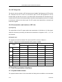
The umbilical cables onboard the launch vehicle are cables from the IFDs (P01, P02) to
WXTC, which will fly with launch vehicle (See Table 5-2).
Table 5-2
Umbilical Cable
Code
P01, P02
EC1, EC2
EY1
WXTC
G1
Description
IFD
Mechanical technological interfaces between
PLA and LV
Interface between umbilical cable and LV TM
system, through which the SC/LV IFD
(J01/P01, J02/P02) separation signal is sent
to LV TM system
Umbilical cable connector (type: JF5-231)
Grounding points to connect the shielding of
the wires to the shell of the LV
(b) Separation Signal
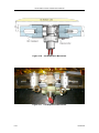
The separation signal is generated through break-wires on the IFDs P01 & P02. The
satellite will receive the separation signals once the break-wires are disconnected upon
separation.
In addition, there are another two break-wires on the IFDs J01 & J02 that will generate the
separation signal for the launch vehicle once the break-wires are disconnected upon
separation. This separation signal will be sent to the launch vehicle telemetry system
through the EY1 interface. The break-wires allow a maximum current of 100 mA and a
maximum voltage of 30 V.
Figure 5-10 shows an example the break-wire circuitry.
5-16
Issue 2011