1
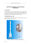
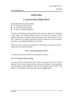
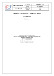
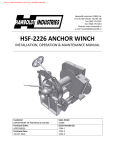
LM-3A USER’S MANUAL CHAPTER 5 CALT'S PROPRIETARY CHAPTER 5 MECHANICAL/ELECTRICAL INTERFACE 5.1 Description The interface between LV and SC consists of mechanical and electrical interfaces. Through mechanical interface, the payload is mated with the LV mechanically, while the electrical interface functions to electrically connect the LV with SC. 5.2 Mechanical Interface 5.2.1 Composition The SC is mounted on the launch vehicle through a payload adapter. The bottom ring of the adapter mates with the VEB of LM-3A by bolts. The top ring of the adapter is mated with the interface ring of the SC through a clampband. On the payload adapter, there are separation springs for the LV/SC separation, cables and connectors mainly used by SC. 5.2.2 Payload Adapter 5.2.2.1 Summary The top ring of the adapter, without any chemical treatment, connects with the interface ring of the SC through an international widely-used interface. The bottom ring of the adapter is 1748mm in diameter and it is connected with the VEB via 70 bolts. LM-3A provides three types of mechanical interfaces, which are 937B, 1194, and 1194A respectively. User should contact CALT if other interface is needed. 5.2.2.2 937B Interface The 937B interface adapter is a 900mm-high truncated cone, whose top ring diameter is 945.26mm and bottom ring diameter is 1748mm. Refer to Figure 5-1a and Figure 5-1b. The top ring, for mating with the SC, is made of high-strength aluminum alloy. The adapter is a composite honeycomb sandwich structure. The core of the sandwich is made of aluminum honeycomb. The facesheets are made of carbon fiber composite. Issue 1999 5-1 LM-3A USER’S MANUAL CHAPTER 5 CALT'S PROPRIETARY The total mass of the adapter is 55kg, including the separation springs, cables and other accessories. 5.2.2.3 1194 Interface The 1194 interface adapter is a 650mm-high truncated cone, whose top ring diameter is 1215mm and bottom ring diameter is 1748mm. Refer to Figure 5-2a and Figure 5-2b.The top ring, for mating with the SC, is made of high-strength aluminum alloy. The adapter is a composite honeycomb sandwich structure. The core of the sandwich is made of aluminum honeycomb. The facesheets are made of carbon fiber composite. The total mass of the adapter is 53kg, including the separation springs, cables and other accessories. 5.2.2.4 1194A Interface The adapter is 450mm high, see Figure 5-3a and Figure 5-3b. Issue 1999 5-2 LM-3A USER’S MANUAL CHAPTER 5 CALT'S PROPRIETARY c 90060.5 0.2 B B 0.2 φ1748 +Y 2 Explosive Bolts 7.5 45 45 30 A +Z A -Z Zoom A 2 IFDs 22.5 4 Separation Springs 2 MircoSwitches -Y Figure 5-1a 937B Payload Adapter Issue 1999 5-3 LM-3A USER’S MANUAL CHAPTER 5 CALT'S PROPRIETARY Section A-A φ 945.26 +0.15 0 0.3 0.5 A +0.5 φ912 0 φ876.9 0.25 3.2 3.2 Detail A 0.25 1.6 13 0.1 A 12 0.15 Detail A Zoom A 0.25 C φ939.97 -0.2 +0 0 2.65 -0.1 0.2 45 R0.13 0.2 45 R0.13 1.53 0.03 0.2 45 17.48 +0.08 0.00 5.84 0.08 A R0.3 0.1 +0.25 60 0 30 0.30 R0.5 15-0.25 1.6 Figure 5-1b 937B Interface Issue 1999 5-4 LM-3A USER’S MANUAL CHAPTER 5 65060.8 CALT'S PROPRIETARY 0.2 +Y 6 Separation Springs 7.5 Zoom A 60 60 A 37.5 A -Z +Z 50 39O 1O 2 Explosive Bolts 2 Microswitches -Y Figure 5-2a 1194 Payload Adapter Issue 1999 5-5 LM-3A USER’S MANUAL CHAPTER 5 CALT'S PROPRIETARY Zoom A 5+0 .05 +Y R603.5 +0.2 0 15 +Z Section A-A 0.08 φ1215 0.2 A 3.2 +0.26 0 3.2 φ1192 φ1131 0.5 A 0.2515 5 15 4 1.6 5 +0.3 0 R1.5 Figure 5-2b 1194 Interface Issue 1999 5-6 LM-3A USER’S MANUAL CHAPTER 5 650 0.8 CALT'S PROPRIETARY 0.2 +Y 6 Separation Springs 7.5 60 A 60 A -Z +Z 2 Microswitches 2 Explosive Bolts -Y Figure 5-3a 1194A Payload Adapter Issue 1999 5-7 LM-3A USER’S MANUAL CHAPTER 5 CALT'S PROPRIETARY Section A-A 0.08 A 0.1 B φ 1215 0.15 0.3 φ1184.28 0.5 3.2 3.2 Detail A 0.25 φ1131 0.5 A 6 +0.3 0 19 0.1 1.6 Detail A φ1209.17-0.13 +0 5.21 0.15 B 2.54 0.03 0.2 45 0.2 45 1.27 0.03 0.2 45 R0.5 R3 15-0.25 1.6 Figure 5-3b 1194A Interface Issue 1999 5-8 LM-3A USER’S MANUAL CHAPTER 5 CALT'S PROPRIETARY 5.2.3 SC/LV Separation System The SC/LV separation system consists of clampband system and separation springs. The clampband system is used for locking and unlocking the SC. The separation springs is mounted on the adapter, which provides relative velocity between SC and LV. Figure 5-4a,b,c,d&e show the SC/LV separation system. 5.2.3.1 Clampband System The clampband system consists of clampband, non-contamination explosive bolts, V-shoes, lateral-restraining springs, longitudinal-restraining springs, etc. See Figure 5-4a. The clampband has two halves. It is 50mm wide and 1.0mm thick. The clampband is made of high-strength steel. The clampband system has two non-contamination explosive bolts. Each bolt has two igniters on the two ends, so each bolt can be ignited from both ends. The igniter on the end has two igniting bridge-circuits. As long as one igniter works, and even only one bridge-circuit is powered, the bolt can be detonated and cut off. There are totally 4 igniters and 8 bridge-circuits for the two bolts. Any bridge of these 8 works, the clampband can be definitely unlocked. So the unlocking reliability is very high. The maximum allowable pretension of the explosive bolt is 45kN. The V-shoes are used for clamping the interface ring of the SC and the top ring of the adapter. The 26 V-shoes for the clampband are symmetrically distributed along the periphery. The V-shoes are made of high-strength Aluminum. The lateral-restraining springs connect the both ends of the two halves of clampband. The lateral-restraining springs are used for controlling the outward movement of the clampband (perpendicular to LV axial axis) and keep the sufficient payload envelope. Refer to Figure 5-4b&c. There are totally 8 lateral-restraining springs in 2 types. Issue 1999 5-9 LM-3A USER’S MANUAL CHAPTER 5 CALT'S PROPRIETARY The longitudinal-restraining springs restrict the movement of the separated clampband toward SC. The two halves of the clampband will be held on the adapter and be kept from colliding with the SC. During the installation of clampband system, 10 strain gauges are installed on the each half of the clampband. Through the gauges and computer, the strain and pretension at each measuring point can be monitored in real time. A special designed tool is used for applying the pretension. Generally, the pretension is 24.2+1.0/-0kN. While the pretension can be adjusted according to the specific requirements of the SC and the coupled load analysis results. For the convenience and safety of the SC during clampband installation, the bottom of the SC is needed to be 85mm away from the SC/LV separation plane, or there should be a distance of 20mm between the lateral-restraining springs and the bottom of SC. This requirement has been considered in the fairing envelopes. 5.2.3.2 Separation Springs The separation springs includes springs, bracket, pushing rod, etc. Refer to Figure 5-4d and Figure 5-4e. The separation springs and their accessories are mounted on the adapter. The system can provide a SC/LV separation velocity higher than 0.5m/sec. It can also provide lateral spinning rate not less than 1.0°/sec according to user’s requirement. 5.2.4 Anti-collision Measures LM-3A has adopted some measures to prevent itself from re-contact with the SC after the SC/LV separation. Two seconds from the instant of separation, the Helium bottle on the third stage of LM-3A will automatically blow out Helium gas in a direction of 45° away from the moving SC. So the reaction thrust will slow down the launch vehicle to make a farther distance between SC and LV. Issue 1999 5-10 LM-3A USER’S MANUAL CHAPTER 5 CALT'S PROPRIETARY Non-contamination Explosive Bolt Lateral Restraining Springs Clampband Detail A Longitudinal Restraining Springs Y A Separation Spring A Z -Z B B -Y Detail B Figure 5-4a Clampband System Issue 1999 5-11 LM-3A USER’S MANUAL CHAPTER 5 CALT'S PROPRIETARY Clampband Dynamic Envelope +Z φ1495 Clampband Explosive Bolt +Y -Y -Z 1315 Figure 5-4b Clampband Dynamic Envelope (For Interface 1194 and 1194A only) Issue 1999 5-12 LM-3A USER’S MANUAL CHAPTER 5 CALT'S PROPRIETARY Detail A SC Interface Ring Bolt Payload Adapter Clampband V Shoe V Shoe Detail B C C Clampband Section C-C Explosive Bolt 100 63 Lateral Restraining Spring Figure 5-7c Clampband in Detail Issue 1999 5-13 LM-3A USER’S MANUAL CHAPTER 5 CALT'S PROPRIETARY Section A-A SC Interface Ring Clampband 2 Mircoswitches Payload Adapter Section B-B φ 1155 Clampband SC Interface Ring Payload Adapter Longitudinal Restraining Spring Pushing Rod Separation Spring Figure 5-4d SC/LV Separation Spring Issue 1999 5-14 LM-3A USER’S MANUAL CHAPTER 5 CALT'S PROPRIETARY Section A-A 4 SC/LV Separation Plane Payload Adapter 2 Microswitches (Extending Status) Bracket φ 1155 SC/LV Separation Plane Payload Adapter Pushing Rod Separation Spring (Extending Status) Figure 5-7e SC/LV Separation Spring (Extending Status) Issue 1999 5-15 LM-3A USER’S MANUAL CHAPTER 5 CALT'S PROPRIETARY 5.3 Electrical Interface 5.3.1 Summary The SC is electrically connected with SC’s electrical ground support equipment (EGSE) through SC/LV electrical interface and umbilical cables provided by LV side. By using of EGSE and the umbilical cables, SC team can perform wired testing and pre-launch control to the SC, such as SC power-supply, on-board battery charging, wired-monitoring on powering status and other parameters. The umbilical system consists of onboard-LV Parts and ground parts. Refer to Figure 5-8 and Figure 5-9. The 350m-cable from Launch Control Console (LCC) to Umbilical Tower, EB26/EB36, BOX3, BOX4, and Power-supply 1&2 are the common to different missions. The onboard-LV cable, as well as ground cable from WXTC to ED 13,14&15 and BOX1 & BOX2, will be designed for dedicated SC according to User's needs. In order to assure the quality of the product, the umbilical system will be provided to the User after undergoing pre-delivery acceptance test and insulation/conductivity checkouts in the launch site. Issue 1999 5-16 LM-3A USER’S MANUAL CHAPTER 5 CALT'S PROPRIETARY J1 BOX1,BOX2: Box Adapter J2 P1 SC/LV Separation Plane P2 BOX3-WXTC: Disconnected Control Box BOX4: Payload Signal Console Dy6.646.1892 Dy6.646.1893 SC side Supplied Included On-board: P1/J1, P2/J2 EC2 EC1 Ground: P1/J1, P2/J2, P3/J3, P4/J4 EY1:LV Telemetry System Interface CLTC Supplied EY1 G1 Dy6.646.1894 WXTC LV/Ground Separation Plane 40m Dy6.646.1895 ED24 KSEYVP-6 2 0.75 ED43 ED44 ED42 P8 8E536-3B KYVRPP 80 0.5 ED23 Underground Power Room 8E535-3B ED22 KYVRP-1 108 0.75 X1 350m EB26 ED13 ED14 ED15 KYVRP-1 108 0.75 BOX 1 Power Supply1 36V10A EB37 EB36 BOX3 EB33 EB46 Power Supply2 36V10A EB56 X31 BOX 2 P5 P6 5m .1897 5m .1898 5m .1899 5m P7 P1 J1 P2 J2 SC Console P3 J3 BOX4 WK 8E70-3B WZT DLWX P4 J4 SC RPS Figure 5-8 Umbilical Cable for SC Issue 1999 5-17 LM-3A USER’S MANUAL CHAPTER 5 CALT'S PROPRIETARY RF LIN K RF LI NK On the Hill RF LI NK RF LI NK On the UmbilicalTower SC T&C RF Field SC BS2 J2 P2 EGSE J1 P1 EC2 TO BOX3 E C1 WXTC 40m G1 ED26 ED13 ED14 ED15 BOX1 ED23 ED24 ED22 X1 EY1(LV Telemetry System) BLOCKHOUSE SC CONTROL ROOM 350m SC Console SC RPS CLTC is responsible for connection. J1 P1 P5 J2 P2 P6 J3 P3 P7 J4 P4 P8 X31 BOX2 ED43 ED44 ED42 Underground Umbilical Cables Figure 5-9 On-board and Ground Umbilical Interface Issue 1999 5-18 LM-3A USER’S MANUAL CHAPTER 5 CALT'S PROPRIETARY 5.3.2 In-Flight-Disconnectors (IFDs) 5.3.2.1 Quantity There are two IFDs symmetrically mounted outside the top ring of the payload adapter. The detailed location will be coordinated between SC and LV sides and finally defined in ICD. See Figure 5-10 for typical IFD location. SC Interface Ring IFD 130 85 Prohibiting Area to SC SC/LV Sep.Plane Figure 5-10 Typical IFD Location 5.3.2.2 Types Generally, the IFDs are selected and provided by the user. It is suggested to use following DEUTSCH products. (DEUTSCH Engineered Connecting Devices, California, US) Code P2 P2 LV Side Type D8179E37-OPN D8179E37-OPY Code J1 J2 SC Side Type D8174E37-OSN D8174E37-OSY Note: (1) The IFDs will separate when disengagement reaches 13.5mm. User can also select other DEUTSCH product according to its needs, such as DBAS7061. (2) Following Chinese-made products are also available, YF8-64 (64 pins), FD- Issue 1999 5-19 LM-3A USER’S MANUAL CHAPTER 5 CALT'S PROPRIETARY 20(20 pins), FD-26(26 pins), FD-50(50 pins), etc. 5.3.2.3 IFD Supply Generally, User provides the whole set of the IFDs to CALT for the soldering on the umbilical cables. The necessary operation and measurement description shall also be provided. (If the user selects the Chinese-made connectors, CALT will provide the halves installed at the SC side.) 5.3.2.4 Characteristics of IFD SC side shall specify characteristics of the IFDs. The specific contents are pin assignment, usage, maximum voltage, maximum current, one-way maximum resistance etc. CALT will design the umbilical cable according to the above requirements. 5.3.3 Umbilical System The umbilical system consists of onboard-LV parts and ground cable parts. 5.3.3.1 Onboard-LV Umbilical Cable (1) Composition The Onboard-LV cable net comprises the cables from the IFDs (P1, P2) to WXTC. These umbilical cables will fly with LV. Whereas: Code P1、P2 EC1、EC2 EY1 WXTC G1 Issue 1999 Description LV/SC electrical connectors at LV side which is crimp-connected to the cables. Technological interfaces between SC adapter and LV Interface between umbilical cable and LV TM system, through which the SC/LV separation signal is sent to LV TM system Umbilical cable connector (LV-Ground) Grounding points to overlap the shielding of wires and the shell of LV 5-20 LM-3A USER’S MANUAL CHAPTER 5 CALT'S PROPRIETARY (2) Circuitry of separation signal There are four break-wires on the IFDs P1 & P2, which generate SC/LV separation signals. The SC will receive the SC/LV separation signals once the break-wires circuitry break when SC/LV separates. In the same way, there are two break-wires on the IFDs J1 & J2. The IFDs will send the SC/LV separation signal to LV once the break-wires circuitry break when SC/LV separates. This separation signal will be sent to LV’s telemetry system through EY1 interface. Refer to Figure 5-11 for the break-wire’s circuitry. The break-wire’s allowable current: ≤100mA, allowable voltage: ≤30V. Break-wire J1 SC Side P1 LV Side Break-wire Break-wire Break-wire J2 SC Side P2 LV Side Break-wire Break-wire Figure 5-11 Break-wire for SC/LV Separation Signal There are two microswitches on the payload adapter to give the mechanical separation signal. This separation signal will also be sent to LV’s telemetry system. Issue 1999 5-21 LM-3A USER’S MANUAL CHAPTER 5 CALT'S PROPRIETARY 5.3.3.2 Ground Umbilical Cable Net (1) Composition The ground umbilical cable net consists of umbilical cable connector (WXTC), cables, box adapters, etc. Refer to Figure 5-8 and Figure 5-9. Whereas: Code WXTC BOX1 BOX2 BOX3 BOX4 Issue 1999 Description WXTC is umbilical cable connector (LV-Ground) whose female half (socket) is installed at the wall of the VEB, while the male half (pin) is attached to the top end of ground cable. The disconnection of WXTC is electrically controlled. (The disconnection is powered by BOX 3 and controlled by BOX 4. In the mean time, forced disconnection is also used as a spare separation method.) Generally, WXTC disconnects at about 8min prior to launch. If the launch was terminated after the disconnection, WXTC could be reconnected within 30min. The SC should switch over to internal power supply and cut off ground power supply at 5 minutes prior to WXTC disconnection. Therefore, during disconnection only a low current monitoring signal (such as 30V, ≤100mA) is permitted to pass through the WXTC. BOX 1 is a box adapter for umbilical cable that is located inside the SC Cable Measurement Room on Floor 8.5 of the umbilical tower. (If needed, BOX 1 can provide more interfaces for the connection with SC ground equipment.) BOX 2 is another box adapter for umbilical cable that is located inside the SC Blockhouse on ground. Other SC ground support equipment (RPS, Console, etc.) are also located inside the Blockhouse. This is a relay box for the disconnection of the umbilical cable. BOX 3 is located inside the under-ground Power-Supply Room. Box 3 is powered by 2 DC regulated power supply sets. These two power supply sets are in “working-state” sparing to each other. BOX 4 is located inside Blockhouse. It is for the control of the pre-launch disconnection of SC (Payload) umbilical cables. 5-22 LM-3A USER’S MANUAL CHAPTER 5 CALT'S PROPRIETARY (2) Interface on Ground Generally, there are four interfaces on ground, namely, two for SC Console (P1/J1&P2/J2), and the other two for SC power supply (P3/J3&P4/J4). SC side will define the detailed requirement of ground interfaces. Those connectors (P1,P2,P3,P4) to be connected with SC ground equipment should be provided by SC side to LV side for the manufacture of cables. Location Code Specification Quantity LV side interfaces P1 P2 P3 P4 To be defined by SC side 2 2 2 2 If LV side couldn’t get the connectors from SC side, this ground interface cable will be provided in cores with pin marks. SC side can also provide this ground cable. The length of this cable is about 5 meters. If so, LV side will provide the connectors (as Y11P-61) to connect with BOX 2. (3) Type & Performance The type and performance of the umbilical cables are listed in Figure 5-8. Onboard-LV Cable Net Generally, ASTVR and ASTVRP wires are adopted for the onboard-LV cable net: ASTVR, 0.5mm2, fiber-sheath, PVC insulation; ASTVRP, 0.5mm2, fiber-sheath, PVC insulation, shielded. For both cables, their working voltage is ≤500V and DC resistance is 38.0Ω/km (20°C). The single core or cluster will be shielded and sheathed. Ground Cable Net Single-Core Shielded Cable KYVRPP 80×0.5, Copper core, PV insulation, copper film plating on PV for shielding of each core, PVC sheath, woven wire net for shielding of cable; 80 cores/cable, 0.5mm2/core; Working voltage: ≤60V; DC resistance (20°C) of each core: z Issue 1999 5-23 LM-3A USER’S MANUAL CHAPTER 5 CALT'S PROPRIETARY 38.0Ω/km. Ordinary Insulation Cable KYVRP-1 108×0.75, copper core with PV insulation, PVC sheath, woven wire for shielding, flexible; 108 cores/cable, 0.75mm2/core; No shielding for each core, woven tin-plated copper wire for shielding of cable; Working voltage: ≤110V; DC resistance (20°C) of each core: 28.0Ω/km. z Twin-twist Shielded Cable KSEYVP 6×2×0.75, 6 pairs of twin-twisted cores, 0.75mm2/core. Each twisted pair is shielded and the whole cable has a woven wire net for shielding. Impedance: 100Ω. z Twin-twist shielded cable (KSEYVP) are generally used for SC data transmission and communication. Single-core shielded cable (KYVRPP) is often used for common control and signal indicating. KYVRP-1 cable is adopted for SC’s power supply on ground and multi-cores are paralleled to meet the SC’s single-loop resistance requirement. Under normal condition, the umbilical cable (both on-board and ground) has a insulation resistance of ≥10MΩ (including between cores, core and shielding, core and LV shell) 5.3.3.3 Umbilical Cable Disconnect Control LV side is responsible for the pre-launch disconnection of umbilical cable through BOX3 and BOX 4, see Figure 5-12. Inside the underground Power Supply Room, there are two 36V/10A DC regulated power supply which will provide power for the cables. They are all in working condition sparing to each other. Generally, according to the count-down launch procedure, only after LV side has received the confirmation that SC has turned to internal power and SC is normal, could the order of umbilical cable disconnection be sent out. Issue 1999 5-24 LM-3A USER’S MANUAL CALT'S PROPRIETARY CHAPTER 5 LV GASPIPE DISCONNECTED LV AIR-CON LV UMBILICAL DISCONNECTED DISCONNECTED 8E70-3B POWER SC UMBILICAL DISCONNECT SC NORMAL LIFT-OFF PAYLOAD SIGNAL CONSOLE IGNITION SC UMBILICAL CONNECTED ON LV INTERNAL POWER POWER SUPPLY 2 ON OFF SC INTERNAL ON OFF POWER SUPPLY 1 ON OFF SC ABNORMAL SWITCH POWER SUPPLY BUS OFF SC NORMAL SWITCH KEY SWITCH SC INTERNAL POWER SWITCH POWER SWITCH EMERGENCY SHUT DOWN SC ABNORMAL SC UMBILICAL FORCED DISCONNECT Figure 5-12 Illustration on the Control Panel of BOX4 0 BUS1 25 (V) BUS2 BUS OFF VOLT MEASURE SWITCH 50 5-25 5-25 Issue 1999 LM-3A USER’S MANUAL CHAPTER 5 CALT'S PROPRIETARY 5.3.4 Anti-lightning, Shielding and Grounding In order to assure the safety of the operations of both LV and SC, some measures have been taken for anti-lightning, shielding and grounding. (1) The cable has two shielding layers, the outer shielding is for anti-lightning while the inner shielding is for anti-interference. (2) For the cables from WXTC to BOX 2, the outer shielding (anti-lightning) has a grounding point every 20m. These grounding measures can assure the lightning and other inductance to be discharged immediately. The grounding locations are either on the swing rods or the cable’s supporting brackets. (3) The inner shield has a single grounding. The inner shields of the on-board cables are connected to BOX 2 through WXTC. BOX 2 has a grounding pole. (4) The inner and outer shields are insulated with each other inside the cables. 5.3.5 Continuity of SC “Earth-Potential” The SC should have a reference point of earth-potential and this benchmark should be near to the SC/LV separation plane. Generally, the resistance between all other metal parts of SC (shell, structures, etc.) and this benchmark should be less than 10mΩ under a current of 10mA. There is also a reference-point of earth-potential at the bottom of the adapter. The resistance between LV reference point at the adapter and SC reference should be less than 10mΩ with a current of 10mA. In order to keep the continuity of earth-potential and meet this requirement, the bottom of SC to be mated with adapter should not be treated chemically or treated through any other methodology affecting its electrical conductivity. 5.3.6 Miscellaneous 5.3.6.1 SC/LV Separation Control (1) The characteristics of the explosive bolts on the clampband is as follows: Ignition Method: Two-end Ignition (Two Bridges on Each End) Quantities: 2 (Redundancy Design) Ignition Resistance: 0.9~1.2Ω for one Bridge Ignition Current: 5~10A for one Bridge (2) Ignition Signal Issue 1999 5-26 LM-3A USER’S MANUAL CHAPTER 5 CALT'S PROPRIETARY According to the flight procedures and time sequence, the onboard computer and programmer send out ignition signal to the explosive bolts to separate LV/SC reliably. The ignition signal has following characteristics: Battery voltage: 30±3V, Signal duration (Impulse width): ≥200ms Working current: 5~10A 5.3.6.2 Special Signal Service If required, the LV time sequence system can provide some signals to SC through the onboard-LV cables and connectors. These signals can either be power-supply or dry-loop signals to be defined by SC side. 5.3.6.3 Special Statement Any signal possibly dangerous to the flight can not be sent to the payload during the whole flight till SC/LV separation. Only LV/SC separation can be used as the initial reference for all SC operations. After LV/SC separation, SC side can control SC through microswitches and remote commands. Issue 1999 5-27 LM-3A USER’S MANUAL CHAPTER 5 CALT'S PROPRIETARY 5.4 RF Links 5.4.1 RF Relay Path The Launch Site can provide RF link from EGSE to SC either in BS or on the umbilical tower. RF link path consists of points A (BS2), B (Relay Station), C (Umbilical Tower), and D (BS3). Refer to Figure 5-13. At point C, there are two antennas, one of which points to SC and the other points to relay station (Point B). There are also two antennas at Point B. The two antennas have the function of amplifying signals. There are interfaces in BS2 to convey the RF signals from/to EGSE. 5.4.2 Characteristics of RF Link (1) Frequency C Band: Ku Band: Up-link: 5925~6425 MHz Down-link: 3700~4200 MHz TBD (2) Signal Level C Band: See following table Ku Band: TBD Frequency Telemetry Command Issue 1999 SC Antenna EIRP PFD 37dBm -85dBW/m2 EGSE Input -70dBm Output 30dBm 5-28 LM-3A USER’S MANUAL CALT'S PROPRIETARY CHAPTER 5 Amplifier RF Link RF Control Panel Power Amplifier Amplifier RF Link Amplifier Power Amplifier Umbilical Tower Power Amplifier Relay Tower POINT C Setup Control Panel BS2 POINT B PreAmplifier BS3 POINT A SC POINT D Figure 5-13 RF Links RF Link RF Link SC LV 5-29 5-29 Issue 1999