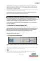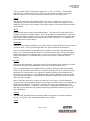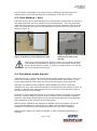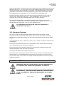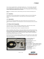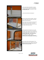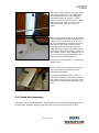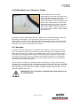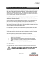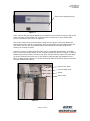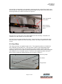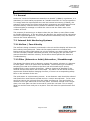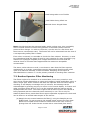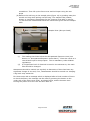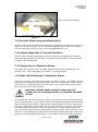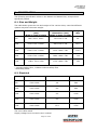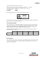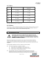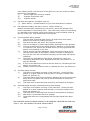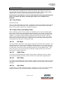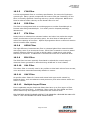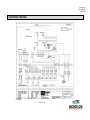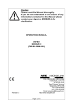
1
©Bioquell UK Ltd (2011). All rights reserved. USER MANUAL TM110-O&M-001 REVISION 2 MONAIR PLUS & MONAIR RECIRCULATORY FUME CUPBOARD USER MANUAL Astec-Microflow Bioquell UK Ltd 52 Royce Close West Portway Andover Hampshire SP10 3TS T: +44 (0)1264 835 835 F: +44 (0)1264 835 836 E: [email protected] W: www.astec-microflow.com Page 1 of 46 USER MANUAL TM110-O&M-001 REVISION 2 Contents 1 SAFETY ................................................................................................ 5 2 DESCRIPTION ....................................................................................... 6 3 GENERAL OPERATING INSTRUCTIONS...................................................... 7 4 3.1 Starting the Monair or Monair Plus .................................................... 7 3.2 Control Panel and Alarms ................................................................. 7 3.3 Front Window / Door ....................................................................... 9 3.4 Procedures inside the unit ................................................................ 9 3.5 Care and Cleaning ......................................................................... 10 INSTALLATION .................................................................................... 10 4.1 Location ....................................................................................... 11 4.2 Assembly ..................................................................................... 11 4.2.1 Base Unit Assembly ................................................................. 11 4.2.2 Head Unit Assembly ................................................................ 13 4.2.3 Assembly on to Stand or Trolley ............................................... 18 4.3 5 6 FITTING AND REMOVAL OF FILTERS ...................................................... 19 5.1 Main Filter .................................................................................... 19 5.2 Pre-Filter ..................................................................................... 21 5.3 Safety Filter ................................................................................. 22 SET UP AND CALIBRATION ................................................................... 23 6.1 7 Services ....................................................................................... 18 Airflow and Filter Calibration ........................................................... 23 6.1.1 Airflow Calibration ................................................................... 23 6.1.2 Filter Breakthrough / Saturation Alarm Setting ........................... 24 6.2 Low Airflow Alarm Adjustment ........................................................ 25 6.3 Service Display ............................................................................. 25 MONITORING ...................................................................................... 26 7.1 General ....................................................................................... 26 7.2 Internal Unit Monitoring Systems .................................................... 26 7.2.1 Airflow / Face Velocity ............................................................. 26 7.2.2 Filter (Solvents or Acids) Saturation / Breakthrough .................... 26 7.3 Routine Operator Filter Monitoring .................................................. 27 7.4 Periodic Monitoring and Maintenance ............................................... 29 7.4.1 Visual Inspection of Overall Condition ........................................ 29 7.4.2 Inspection for Electrical Safety ................................................. 29 7.4.3 Filter Breakthrough / Saturation Alarm ...................................... 29 7.4.4 Airflow Measurements ............................................................. 30 7.4.5 Containment .......................................................................... 30 Page 3 of 46 USER MANUAL TM110-O&M-001 REVISION 2 7.4.6 8 Filter Monitoring and Seal Integrity Check .................................. 30 SPECIFICATION ................................................................................... 31 8.1 Size and Weight ............................................................................ 31 8.2 Electrical ...................................................................................... 31 8.3 Environmental .............................................................................. 32 8.4 Airflow ......................................................................................... 32 8.5 Filters .......................................................................................... 33 8.6 Options ........................................................................................ 33 9 TROUBLESHOOTING ............................................................................ 33 10 FILTER TYPES .................................................................................. 35 10.1 Pre-Filters .................................................................................... 35 10.2 Main Filter and Safety Filter ............................................................ 35 10.2.1 GP Filter ................................................................................ 35 10.2.2 AMM Filter.............................................................................. 35 10.2.3 ACI Filter ............................................................................... 35 10.2.4 SUL Filter ............................................................................... 35 10.2.5 CYN Filter .............................................................................. 36 10.2.6 FOR Filter .............................................................................. 36 10.2.7 ETH Filter ............................................................................... 36 10.2.8 HEPA Filter ............................................................................. 36 10.2.9 EDU Filter .............................................................................. 36 10.2.10 OAL Filter ........................................................................... 36 10.2.11 OAC Filter ........................................................................... 36 10.2.12 Multiple Layer Filters ............................................................ 36 11 UK OCCUPATIONAL EXPOSURE LIMITS 2002 ....................................... 37 12 ELECTRICAL DRAWING ..................................................................... 39 13 APPENDIX 1: NOTES ON COSHH REGULATIONS (UK ONLY) ................... 40 14 APPENDIX 2: EC DECLARATION OF CONFORMITY................................. 42 15 APPENDIX 3: WARRANTY .................................................................. 43 Page 4 of 46 USER MANUAL TM110-O&M-001 REVISION 2 1 SAFETY SAFETY OBSERVANCE IS ESSENTIAL WHEN USING THIS EQUIPMENT. READ THIS SECTION CAREFULLY BEFORE USING THE EQUIPMENT Installation should only be carried out by Bioquell trained and approved engineers or agents. Bioquell or its agents cannot accept responsibility for damage, loss or injury caused by, or resulting from, incorrectly installed equipment by third parties. Disconnect the power supply before removing any of the three electrical covers. They are located at the back of the front cover, and the other two on the right hand side in the top housing. Live electrical components are located inside these covers Disconnect the power supply if ever unplugging any of the electrical components such as lights or fans. This may occur if changing the light fitting, or disassembling the unit. Disconnect Power supply when changing filter or without filters in place, as there is possible access to the fan which could result in severe injury and loss of fingers. Do not operate without the safety filter or top cover, which ever is fitted, as there is possible access to the fan which could result in severe injury and loss of fingers. Change filters according to the method described otherwise the person may damage themselves. Install the correct filter for chemicals used and fit the filter as instructions otherwise there may be a chemical vapour hazard. Test the filters regularly (minimum every 14 months) as detailed to prevent a chemical vapour hazard. Do not operate with a low airflow as this may cause a chemical vapour hazard. The Monair and Monair Plus are not explosion proof rated. They are not designed to be located within explosive or flammable environments, or explosive chemicals or procedures located within them. Keep Front window down when practical otherwise the air inflow will reduce and a Chemical vapour hazard could occur. When opening the window fully open, hook the window onto the top of the front cover to stop it falling and causing injury. Ensure the water connections (if fitted) are made properly when fitting to prevent leakage and potential slip hazard, and do not move the unit without disconnecting first. Page 5 of 46 USER MANUAL TM110-O&M-001 REVISION 2 Ensure the drain pipe (if fitted) is flushed with clean water prior to disconnection Ensure the gas system (if fitted) is connected and tested by a suitably competent technician (CORGI registered in the UK). Ensure the power sockets (if fitted) are wired independently to the Monair’s power supply as appropriate. A suitably trained and qualified electrician should be used. 2 DESCRIPTION The Monair and Monair Plus range has been designed to meet the British Standard BS7989:2001 Specification for recirculatory filtration fume cupboards. It has also been tested to EN61010 for electrical safety as well as EN 61326-1, EN61000-3-2 and EN61000-3-3 for EMC requirements. The Monair and Monair Plus are designed to safely remove chemicals and particulates from within the cabinet. A number of different chemicals and combinations of chemicals or particulates can be removed. The units being recirculatory do not require expensive duct work to remove the fumes to outside the building. The air is drawn in through the opening in the front window, drawing all the fumes/particulates up through a pre-filter followed by the main filter. The correct selection of main filter is required to ensure the vapours/particulates are removed. The air then passes through a fan and out the top of the unit. An additional safety filter can be fitted to the top of the unit if required. The filter saturation detector is located at the outlet of the fan if fitted. The sample ports, which can also be used as DOP ports are located above the fan. The efficiency of the filter can be effectively checked at this point. Page 6 of 46 USER MANUAL TM110-O&M-001 REVISION 2 All the models in the range have electronic control of the fans, enabling a fan speed to be set by the operator. There is also an alarm which is set to warn the operator that there is a low air inflow. The controls are set in an easily cleaned touch pad with an adjacent display. The front folding window, side and back windows are all made of acrylic. The rest of the unit is made of powder coated mild steel. Under BS7989:2001 the airflow and filters must be checked at least every 14 months. This can be incorporated into an annual service. 3 GENERAL OPERATING INSTRUCTIONS The Monair and Monair Plus fume cupboards may only be operated with the correct filter installed for the application, according to information supplied by the purchaser. Refer to Section 10 of this manual for further information. If in doubt, call Bioquell directly, or contact your local agent. The following instructions are to be carefully adhered to once the unit has been set-up and calibrated. 3.1 Starting the Monair or Monair Plus To start the unit, turn the power on at the mains socket (there is no power switch on the unit itself). The fans and the lights (if fitted) will come on immediately and the airflow warning light and the alarm light will flash on the control panel, for a short time. The inflow velocity will take approximately one minute to stabilise, then will operate at the pre-set value, this will normally be 0.5 m/s. The airflow is constantly monitored and displayed. The filter monitoring system constantly checks for filter saturation (if fitted). An alarm will sound if either function is out of the set criteria. 3.2 Control Panel and Alarms Figure 1: Monair and Monair Plus visual display and a push button control panel The following is a description of each key and indicator as shown in figure 1 and how they are to be used and what they indicate. FAN The fan can be switched off (and on) using the FAN On/Off button. When switching the fan off the green indicator will go off. Page 7 of 46 USER MANUAL TM110-O&M-001 REVISION 2 The fan speed may be controlled using the (+) and (-) buttons. The display indicates the current face velocity. When the fan speed is altered it will take about a minute for the inflow velocity to settle down to the new value. LIGHT The lights illuminate automatically when the unit is switched on, and can be switched off (and on) using this button. This may be useful overnight or at the weekend if the unit is left running. If the light option is not fitted then the button is redundant. MUTE Pressing this button mutes the audible alarm. The alarm will reset itself if the condition causing the alarm alters. If the mute switch is operated and a second subsequent alarm condition occurs, then the audible alarm will sound again and the Control Panel indicator will confirm the cause of the alarm, i.e. Airflow Low, Filter Saturated or Door Open. AIRFLOW There are two airflow indicators, one green which is Airflow OK and one red which is Airflow Low. During normal operation the green indicator should be lit. If the red light flashes (accompanied by a flashing red Alarm light and audible alarm), this indicates that the airflow is reduced and the face velocity has fallen below the alarm limit, normally set to 0.4 m/s. Corrective action should then be taken see Section 9 Troubleshooting, as this may cause a chemical vapour hazard. FILTER There are two indicators, one green which is Filter OK and one red which is Filter Saturated. During normal operation the green indicator should be lit. If the red light flashes (accompanied by a flashing red Alarm light and audible alarm), this indicates that fumes are breaking through the filter, caused by filter saturation or overload due to a spillage or similar incident. On the Monair the filter alarm is optional, so if not fitted this alarm will be disabled. There may be chemical vapour hazard, so appropriate immediate measures ought to be taken, and the filter changed. Note: The filter saturation system can be one of two types, an acid detection system which is temperature stable or the organic detector which is susceptible to temperature changes. The detector systems are set up and calibrated in the factory before delivery. However, if the alarm is flashing/sounding when unit is first set up, the detector may require adjusting as defined in Section 6 ‘Set up and Calibration’. ALARM This red light will flash and the audible alarm will sound if an alarm condition occurs, i.e. Airflow Low, Filter Saturated or Door Open. DOOR Page 8 of 46 USER MANUAL TM110-O&M-001 REVISION 2 If the red Door light flashes (accompanied by a flashing red Alarm light and audible alarm), this indicates that the middle panel of the door is open. 3.3 Front Window / Door The face velocity at the working aperture (and therefore containment of fumes) is at a maximum with the front window in the closed position. The unit should be used with the front door in the closed position whenever practical. There are two locks on the Monair Plus and one on the Monair to secure the front door shut as shown in figure 2. Figure 2: Window in locked-down position Figure 3: Window secured open with lock located in top bracket When fully opening the front window, secure it by locating the door lock handle in the bracket at the top of the front panel on the right hand side as shown in figure 3. If this is not done there is a risk the door may fall and cause injury. 3.4 Procedures inside the unit A Bunsen burner or other heat source should not be placed too close (<150 mm) to the side or back panels. It is not recommended that an open flame or heat source be positioned closer than 300 mm from the bottom of the filter bed. Although the Glass Reinforced Plastic (GRP) spillage tray has a chemically resistant gel coat, spilt chemicals should be removed from the surface as soon as possible. Likewise if the Polypropylene tray is fitted any chemical spills ought to be removed as soon as possible. It should be noted that filter blocks do not adsorb carbon monoxide or hydrogen. However, small quantities (such as used in schools) will not present a hazard because of the large dilution factor from the airflow through the fume cupboard, and retardation of the chemical in the filter matrix. Bioquell fume cupboards are designed to handle fumes and vapours given off during normal laboratory procedures. It is NOT recommended that large quantities of solvents or acids should be boiled off in the fume cupboard. Always keep a spare set of filters available, in case unplanned replacement is required. Page 9 of 46 USER MANUAL TM110-O&M-001 REVISION 2 High concentrations of fumes entering the filter block may temporarily reduce the filtration efficiency. For this reason any major spillage within the fume cupboard should be cleared up immediately, preferably using spillage absorption granules (available from laboratory chemical suppliers), rather than tissue paper which may aggravate the evaporation of toxic fumes from the spillage area. Following a major spillage, the main filters must be changed, as the heat of wetting may reduce filter efficiency. After stabilisation, the old filters can normally be re-used, provided saturation has not been reached. The electrical equipment in the cabinet including light fittings and control equipment are out of the air stream containing fumes, only the fan is in the air stream after the main filter, it is of a ‘non-sparking’ type. The equipment should not be used in an explosive or flammable atmosphere. 3.5 Care and Cleaning The unit is made of mainly powder coated steel and acrylic plastic. These materials can be cleaned with detergents. Do not clean around any electrical component or electrical housing, but the control panel and screen can be wiped down. The Polypropylene tray or GRP tray, which ever is fitted, can also be cleaned with a detergent. Do not use any abrasive solutions or materials to clean as this will scratch the unit, especially the tray and acrylic windows. Do not use any strong solvents directly on the internal surfaces as they may damage the paint work and melt the plastics. Do not try and clean the surface of any filters. Be careful when cleaning around the airflow sensor, fitted to the right hand side window that it is not damaged and no object is put through or into the orifice. The two fine wires in the orifice can easily be damaged and will cause the unit to no longer function. 4 INSTALLATION WARNING: INSTALLATION SHOULD ONLY BE CARRIED OUT BY TRAINED AND APPROVED ENGINEERS OR AGENTS. BIOQUELL OR ITS AGENTS CANNOT ACCEPT RESPONSIBILITY FOR DAMAGE, LOSS OR INJURY CAUSED BY, OR RESULTING FROM, INCORRECTLY INSTALLED EQUIPMENT BY A THIRD PARTY. Page 10 of 46 USER MANUAL TM110-O&M-001 REVISION 2 The units are supplied with a removable spillage tray. If required the open base can be positioned over an existing utility such as a sink, or on a balance bench, and used without the spillage tray. However in this configuration the front bottom corners must be secured to the work surface. The unit is complete with an electrical plug and only requires the fitting of the filters. 4.1 Location The Monair must be located away from draughts or doors, as this will adversely affect the air monitoring system on the side of the unit and cause nuisance alarms. 4.2 Assembly The filters are packed separately and require fitting into the Head Unit of the machine before operation. For instructions on how to fit the filters refer to section 4. 4.2.1 Base Unit Assembly The base unit only requires assembly outside the UK; within the UK it will be delivered complete, unless circumstances dictate otherwise. Follow the instructions given below to assemble a Base Unit: Open the package when laid flat; remove the plastic panel and tray from the top. Remove the top set of blue packing material; this will reveal the front screen, and four long white metal members, labelled as extrusions, and a packet of parts including the assembly tool. The parts included are shown with their description. Remove these items and set to one side. Remove the next set of blue packing material; this will reveal the two side panels. Care must be taken with the anemometer protector, a plastic disc secured to the right hand side panel. 1 x Roll of Sealing foam 2 x Blanking Plates 1 x Assembly Tool 16 x Black Securing Screws 4 x Large Nuts 4 x Large Washers 1 x Brass Nut 2 x Fan Washers Only supplied if trolley 1 x Brass Washer or stand also supplied 1 x Brass Bolt (see section 4.2.3) 4 x Window securing screws 4 x Small washers 4 x Small Nuts 4 x White plastic Washers 4 x Black caps Page 11 of 46 USER MANUAL TM110-O&M-001 REVISION 2 Place right hand side panel up right, and secure the bottom rear extrusion with two black securing screws using the assembly tool. Secure the left hand side panel. Remove the protective plastic coating off the back panel and slot it into the bottom rear extrusion Fit the top rear extrusion ensuring the back panel is fully down in the slot. Secure both ends of the extrusion with the black securing screws Fit the top front extrusion (93) with the black securing screws, but place a blanking plate between the screw head and the side panel. The side of the blanking plate with more metal must face towards the back. Before tightening the screws push the front extrusion as far as possible to the front. Then fit the front window panel. The panel fits up into the recess in the front extrusion and is secured with the four window securing screws. Page 12 of 46 USER MANUAL TM110-O&M-001 REVISION 2 The white plastic washer must be under the screw head, and on the back the small washer and nut. This assembly requires tightening up with a cross head screw driver and a spanner. Then place the black caps over the screw head, they will ‘click’ securely into place. Take the last long metal strip called the front strengthening angle, and fit to the bottom front of the base unit. The ‘lip’ on the strengthening angle must be at the front of the front, and the ends must be inside the side panels. The strengthening angle is secured at both ends with the black securing screws on the outside, and a large washer and nut on the inside. Using the assembly tool and a spanner tighten these up. If the unit is to be fitted to a trolley see section 4.2.3 Push in the tray fully back, the front of the tray should sit behind the front strengthening angle. Finally fit the sealing foam. It has a self-adhesive back, and must be laid all the way around the top. Ensure a good butt joint is made at the beginning and end. 4.2.2 Head Unit Assembly The Head unit must assembled by two people due to the weight and shape of the components. Suitable staging must be used to ensure that every lift is safe. Page 13 of 46 USER MANUAL TM110-O&M-001 REVISION 2 4 x Pre-Filter Securing Clips (Qty model specific) 16 x Cross Head Screw (Qty model specific) 12 x Metal Washer (Qty model specific) 2 x Large White Washer and Large Dome Cap 2 x Nut, locking washer and metal washer 2 x Small Cross Head Screws 2 x Small White Washers and Dome Caps 4 x Countersunk Head Screw The quantities given and shown are for the 1.0, 1.25 & 1.5m sizes, additional fasteners will be included for the 1.75m version and if Safety filters or other options are fitted) To unpack the head unit, remove the cardboard packing covering the top and sides. Then remove the bag of loose parts which will contain the above parts, and front cover and place to one side, followed by the two blue packing pieces. This will reveal the fan/filter units sitting on cardboard trays. Lift these units out and place to one side (20kg each). Remove the trays and place the outer enclosure (25 kg for the 1.75m size, less for the smaller sizes) on the base unit after ensuring the base unit has been fully assembled and is securely fitted on a bench, stand or trolley. WARNING The Anemometer (black disc) and door switch (if fitted) will hang down when moving the enclosure, ensure they are not trapped or damaged when placed on the enclosure. Page 14 of 46 USER MANUAL TM110-O&M-001 REVISION 2 Secure the outer enclosure to the base unit. Two cross head screws must be fitted with a large white washer under the head at the back of the unit as pictured. Then snap on the large white dome cap. Inside the base unit at the front there are two more securing points. These require a cross head screw with metal washer under the head fitted upwards, and a locking washer, metal washer and nut securing it. Next, lift each Fan/Filter unit and put in place. It fits over the large rectangular hole in the bottom of the outer enclosure. Secure the Fan/Filter unit with six cross head screws with metal washers under the head. Note that the front two must have the Pre-Filter securing clip fitted under the cross head screw and no washer, as shown. Pre-Filter Securing clips Once the heads have been fitted, the Pre-Filter supporting frame can be placed in position. This fits over the lip at the back, which acts as a hinge point, and then is secured in the clips at the front. For fitting the Pre-filter see section 5.2. Page 15 of 46 USER MANUAL TM110-O&M-001 REVISION 2 Then attach the anemometer (black disc) to the side panel. Remove the three screws holding the protector disc from the INSIDE of the enclosure. Then remove the tape protecting the anemometer and replace the three screws and secure through the anemometer into the protector disc on the outside. Ensure the screw heads go into the countersunk holes in the black plastic (if there are no countersunk holes the Anemometer is facing the wrong way). Then fit the door switch bracket (if option supplied). This is secured with the two nuts which are already fitted to the studs located behind the right hand window frame near the top. Use the nuts to secure the bracket in place. Connection Next connect the Fan/Filter units power by plugging in the free plug on the outer enclosure local to the Fan/Filter unit into the socket fitted to the back right of the Fan/Filter unit. Then connect the tube at the back of every Fan/Filter unit into either the ‘T’ or inline hose barb. Fit the front cover (12kg max) by securing it to the outer enclosure, using the pre-fitted hinges. Two countersunk head screws are required per hinge. Page 16 of 46 USER MANUAL TM110-O&M-001 REVISION 2 Once the front cover has been fitted, lift it open and hold in position with the two side stays. Then connect the large and small white plastic plug on the outer enclosure to the two sockets on the inside of the front cover, then connect the Earth wire to the stud, and tighten the nut down firmly, finally fit the tube into its socket by pushing the tube in firmly. Note if the sensor option has not been fitted there will be no tube. The Filters can now be fitted, see section 5.1 for the main filter and section5.3 for the safety filter if option fitted. Finally shut the front cover and screw it closed. It is secured with the two small cross head screw with a small white plastic washer under the screw head. Then snap on the small white dome cap, as done previously when securing the Head assembly to the back of the base unit. The power lead is plugged into the socket at the top right hand side of the unit. Check that the filters have been installed, and then turn the power on. Page 17 of 46 USER MANUAL TM110-O&M-001 REVISION 2 4.2.3 Assembly on to Stand or Trolley Place the Base Unit on to the trolley/stand. Do not try and slide it on as the black bolt heads at the back will clash with the trolley/stand sides. Ensure the Base unit is hard against the back of the trolley/stand. Then fit the brass bolt through the hole at the back right of the base unit down, it must have a fan washer under the bolt head. Secure with a fan washer, brass washer and brass nut. On some units two brass bolts with fan washers are required instead, these are fitted from underneath. They go through two holes at the back of the trolley/stand on either side. The bolts require securing using the fixed nut in the base of the enclosure. It is important that the fan washer cuts into the paint on the base unit to give a good earth connection. 4.3 Services A double electrical socket can be supplied as an option to either the unit on its own, or as part of the trolley or stand. In both cases there is a separate power cable which ought to be wired to a suitable mains supply. The sockets are not powered off the supply to the cabinet. The sockets are located on the outside of the cabinet to prevent fumes or liquids adversely affecting them. All electrical equipment used within the cabinet must be suitably rated for the atmosphere, chemicals and liquids being used. There is also an option of a gas tap fitted to the stand or trolley. This must be connected and checked along with the gas system within the cabinet by a suitably qualified and competent person (CORGI registered in the UK). The gas outlet at the trolley/stand is a brass quick release coupling Flowtech part No TH1-11-002 1/8” IPL (Rectus Type 72). WARNING Ensure the drain is flushed with clean water prior to disconnection. Page 18 of 46 USER MANUAL TM110-O&M-001 REVISION 2 5 FITTING AND REMOVAL OF FILTERS Hazards associated with the removal and disposal of used filters will depend on the use to which the filtration fume cabinet has been put. If an activated carbon filter is used with hydrocarbon solvents, the filter will retain the solvents without loss, and can be removed in the open laboratory. A pair of plastic gloves and a plastic bag is supplied with each filter. The plastic gloves should be used when removing filters. The used filters should be placed in the plastic bag and sealed prior to waste disposal, preferably by incineration. If dangerous materials such as asbestos dust or radioactive chemicals have been contained by the filter, then operator protection which includes the use of respirators and protective clothing may be required. The used filter may require disposal by a specialist company. As the conditions of use are outside Bioquell’s control, it is the responsibility of the user to ensure that any personnel changing filters are advised of any potential hazards in handling the filters, and are provided with any necessary protective equipment or clothing. The safety officer ought to be able to advise. The changing of the filters is the same for all of the Monair and Monair Plus units, only the number of filters varies between units. It is important to note that once the sealed bags containing carbon filters have been opened they will absorb water from the atmosphere. Therefore after 24 months the filters potential life cannot be assured and should be replaced. The filters once fitted ought to be tested as described in section 7.3. This will confirm that the filter is correctly fitted and is adsorbing the fumes as intended. The filters ought to be changed under the following circumstances: • • • • • • Failure of a filter test, done as part of the monitoring routine, see section 7. The filter breakthrough alarm sounds and the procedure described in section 7.3 is carried out. Other monitoring devices within the environment are activated. A spill or procedure is carried out which may have overloaded the filter. As part of a routine maintenance programme. An unusual or a stronger than normal smell is detected. 5.1 Main Filter To fit the Main filter, switch off the power to the Monair at the mains socket. WARNING: DISCONNECT POWER SUPPLY WHEN CHANGING FILTER. DO NOT OPERATE WITHOUT FILTER IN PLACE, DANGER OF ROTATING PARTS. Page 19 of 46 USER MANUAL TM110-O&M-001 REVISION 2 Front Cover holding screw Figure 4 Then remove the two white plastic screw head covers located on either side of the front cover by prizing them off. Undo the two screws with a cross-head (Pozidrive) screwdriver, as shown on figure 4. Lift-up the front cover and hold open using the two props. Then pull down the fan-housing lever until it is horizontal. Put on the plastic gloves supplied with the new filter. Pull out the two sliders which are located on the side of each fan housing if no filter is fitted. If there is a filter in place pull the filter out by its handle horizontally, and when fully out swing the filter down to the vertical position as shown in figure 5. Place a plastic bag over the filter, and then the filter can be held on either side and lifted up so the yellow lugs come out of the sliders. Seal the bag and dispose of the filter in appropriate manner. To fit the new filter place the yellow lugs on the filter into the sliders from above. Front cover Prop Fan-housing lever Slider Filter Lugs Figure 5 Page 20 of 46 USER MANUAL TM110-O&M-001 REVISION 2 Lift the filter horizontally by the handle, checking that the yellow filter label is the correct way up. Then slide the filter all the way back to the end of the slide until it cannot go back any further as shown on figure 6. Filter being slid into place Fan-housing Lever pushed back Figure 6 Lift the lever-up and push it fully back against the fan housing. Complete the ‘Installed on’ date details on the filter label. Lift the front cover and release the props. Drop the front cover props and close the front panel. Replace the two securing screws, and finally replace their white covers. 5.2 Pre-Filter The white pre-filter is supplied ready to fit. The supporting frame is located on the underside of the head unit. The pre filter is laid on the supporting frame (which is hinged at the rear) and the frame is then pushed up into the front retaining clips. If the pre-filter is being replaced the old pre-filter must be bagged and disposed of in a suitable manner. Access to the supporting frame and prefilter is from inside the cabinet base as can be seen in figure 7. Securing Clips Pre-Filter Hinge Point Figure 7 Page 21 of 46 USER MANUAL TM110-O&M-001 REVISION 2 5.3 Safety Filter If a safety filter is fitted then this can be replaced by the following method: • Safe access to the top of the cabinet is required, such as a step ladder. • Switch off the power to the Monair at the mains socket. WARNING: MOVING PARTS HAZARD, POWER MUST BE TURNED OFF AT THE MAINS PRIOR TO REMOVING THE EXISTING SAFETY FILTER. Put on the plastic gloves supplied with the new filter. Complete the ‘Installed on’ date details on the new replacement filter. Remove the filter frame retaining screws on the top of the Head Unit with a crosshead (Pozi-drive) screwdriver. Lift off the existing filter and replace with a new filter ensuring that the label is the correct way up and facing to the front, so that it can be seen through the window, see figure 8. Screw the retaining frame in place to seal the filter securely. Place the old filter in a plastic bag and dispose of in an appropriate manner. Three Securing Screws Three Securing Screws Safety Filter Label Figure 8 Page 22 of 46 USER MANUAL TM110-O&M-001 REVISION 2 6 SET UP AND CALIBRATION 6.1 Airflow and Filter Calibration The Monair and Monair Plus are set-up at the factory and tested. It then will require calibration on site; also checks are required to ensure that the airflow is not being disrupted by open windows, doors or air vents. The Monair range has been extensively tested to BS 7989:2001 at 0.5m/s. Compliance to the standard cannot be guaranteed at different average inflow velocities. 6.1.1 Airflow Calibration To calibrate the cabinet carry out the following procedure: a) Switch on the power to the cabinet. Allow the fan to stabilise and the electronics to warm up for approximately 10 minutes. Ensure that the door is fully closed. b) Measure the average inflow velocity using a 60 to 100mm diameter paddle wheel anemometer positioned at the following points: Equal distance between measuring points, with max distance of 350mm 200-300mm height of window opening 75mm from top, bottom and both sides For over 300mm high window a middle row of measuring points is required, equally spaced between the top and bottom rows, and with the top and bottom maintaining their 75mm offset from the top and bottom. Ensure that the unit is empty. Remove from the vicinity all equipment not involved in the test. Using no more than one person, fix or hold the anemometer at the first measuring position in such a way that the disturbance to the air flow in the aperture is minimized. Ensure that the anemometer is in the direction for which it was calibrated. Using a stop watch take three readings over a period of 30 seconds such that they are taken at approximately 15 second intervals and enter those in the first column of a table of a suitable format. Repeat at all other positions. Calculate the arithmetic mean for each point, and then calculate the arithmetic mean of the individual point means. Place the anemometer at a position which gave the same average inflow as the total mean. c) Switch off the power to the cabinet. Page 23 of 46 USER MANUAL TM110-O&M-001 REVISION 2 d) Press and hold the MUTE button on the Control Panel and switch the power back on. e) Release the MUTE button. The green and red AIRFLOW LED’s will flash alternately and ‘Calibrating’ will be displayed at the top of the screen, indicating that the cabinet is now in the airflow calibration mode. Wait about 5 minutes for the cabinet to settle. f) Using the fan speed (+) and (-) buttons, adjust the reading on the front panel LCD to the reading on the anemometer, which ought to be as close as possible to the total mean value obtained in paragraph (b). g) Press and release the MUTE button to save the setting to memory. The AIRFLOW LED’s will stop flashing indicating the completion of the airflow calibration. The unit ought to be set to run at 0.5 m/s with all filters apart from CYN filters. NOTE that if using CYN filters or combination filters including CYN the airflow of 0.5m/s will not be possible and the inflow velocity and alarm limit must be reduced accordingly. To change the Low inflow alarm set point refer to section 6.2 of the manual. It is strongly recommended that the local service agent carries out the above procedure. 6.1.2 Filter Breakthrough / Saturation Alarm Setting This procedure will only be required if a new board is fitted. (a) Switch power off to the cabinet (b) Press and hold the LIGHT button whilst switching the cabinet power back on. (c) Release the LIGHT button. The filter saturation alarm LED’s will start flashing alternately. This is now in calibration mode. If an acid sensor is to be used with the Monair plus then the calibration of the unit needs to be performed with a 200 KΩ resistance connected between Pin 2 and Pin 3 of PL8 on the main control PCB. Note: The Acid sensor must be disconnected from PL8 during the calibration process. (d) Leave the unit for a minimum of 15 minutes if powered from cold to allow the sensor to warm to operating temperature. (e) Press the light button once, the unit will accept calibration and exit to normal run mode. (f) Check that the sensor is working according to section 7.4.3 of the manual. If an Acid sensor, reconnect the acid sensor after the calibration process has been completed. Without any paper in the holder the filter alarm must be on. With unexposed Congo red acid detection paper inserted in the holder the filter alarm must be off. Page 24 of 46 USER MANUAL TM110-O&M-001 REVISION 2 With exposed Congo red acid detection paper inserted in the holder the filter alarm must be on. Note: Congo red acid detection paper will be blue after exposure. It is strongly recommended that the local service agent carries out the above procedure. 6.2 Low Airflow Alarm Adjustment The low airflow alarm is set as default to 0.4 m/s, in accordance with the type test. However if this requires adjustment for particular applications, this can be carried out by following the procedure below: (a) Switch off the power to the cabinet. (b) Press and hold the FAN button on the Control Panel and switch the power back on. (c) Release the FAN button. ‘Low Airflow Alarm’ will be displayed at the top of the screen, indicating that the low airflow alarm can be set. (d) Using the fan speed (+) and (-) buttons, adjust the alarm level to the value required (e) Press and release the fan button to save (f) Turn off the cabinet 6.3 Service Display When the fan is switched off the Bioquell approved agent’s name will be displayed on the screen. In the UK it will display, ‘UNIT SUPPLIED BY BIOQUELL’. After 30 seconds the display gives an appropriate telephone number of the local service organisation. After a further 30 seconds ‘SERVICE AT LEAST EVERY 14 MONTHS’ is displayed on UK units to comply with BS 7989. A similar message may be displayed in other countries depending on local regulations. The display will cycle through these screens until the fan is switched on. In some countries a message will be displayed after a fixed number of hours of the unit running informing the user that the unit requires servicing. To clear the message any key can be pressed. The service agent will remove the reminder at their visit. Page 25 of 46 USER MANUAL TM110-O&M-001 REVISION 2 7 MONITORING 7.1 General Under the "Control of Substances Hazardous to Health" (COSHH) regulations, it is mandatory to check safety equipment at "suitable intervals" for correct operation. To comply with the requirements the unit has internal monitoring (if fitted), the operator must monitor the filters and periodic monitoring and maintenance must be performed by a trained service person as detailed in this section. Some versions display a message to remind the user to test the filters after a set number of hours. The purpose of monitoring is to detect when the pre-filters or main filters cease to operate effectively. If the pre-filters are blocked, the airflow will be reduced at the fume cupboard aperture. If the main filters are saturated, they will cease to remove the fumes effectively. 7.2 Internal Unit Monitoring Systems 7.2.1 Airflow / Face Velocity The airflow is being constantly monitored in the unit and the display will show the face velocity being achieved. When the fan speed cannot be increased any further and the airflow falls below 0.4 m/s the Airflow Low alarm will be activated. This will normally indicate a blocked pre-filter, and changing the pre-filter will restore the airflow and face velocity. If the alarm should persist see Section 9 Troubleshooting. 7.2.2 Filter (Solvents or Acids) Saturation / Breakthrough The Monair Plus has a built in detection system for organic solvents or a detector for acid gases. This is an option with the Monair. The monitoring is constantly sampling the total air from above the filter and will therefore pick up any breakthrough in any portion of the filter. When a chemical is detected in the exhaust air the Filter alarm will be activated. The alarm can be muted and the experiment finished before changing the filter, if there is a corresponding safety filter on the exhaust of the unit. The acid sensor is a colorimetric process. A new detector card should be ordered and fitted when new filters are fitted and on a routine annual basis. To fit a new card first remove the old card from the holder see figure 9. The card holder is located on the right hand end of the front panel. The black outside cover hinges down, the inner part can then be moved to reveal the red card. This is simply lifted out and the new card put in its place. This will reset the optical sensor and alarm. Page 26 of 46 USER MANUAL TM110-O&M-001 REVISION 2 Card being taken out of holder Card Holder being Lifted out Outside Cover Hinged Down Figure 9 Note: Should the alarm be activated again within a short time, this is probably due to a small amount of fume being present in the head section from the previous filter change. In order to clear this, run the unit for a few hours and then insert a new detector card. The fumes will not be exhausted into the room if a corresponding safety filter is fitted. If an odour is noticed, it is sensible to check the fume cabinet. However, it must be remembered that the sense of smell is very sensitive for some chemicals (e.g. ammonia or hydrogen sulphide) and a slight smell does not mean that the exhaust levels of chemical have approached the maximum acceptable concentration. The alarm, either solvent or acid, is not there to warn that the filter requires replacement; it is purely a secondary warning device and should not be relied upon as a definitive indicator of filter condition. Sampling of the filters as described below in section 7.3 is the primary method of checking filter condition. 7.3 Routine Operator Filter Monitoring The filters ought to be checked on a routine basis, once every month to once every three months depending on usage and company Health and Safety policy or after a major spill. Some versions will warn the operator that the filters require checking. It will display a message every 6 minutes, the message can be acknowledged by pressing any key to return to the normal display. In France and other countries where NFX 15-211 is to be complied with the warning will be displayed after 60 hours. The check ought to be carried out when the cabinet is being operated with the chemicals most commonly in use. This is only for Gaseous phase filters, particulate filters require specialist equipment to check and can be done on an annual basis as part of the service. (a) Sample the air stream between the filter(s) using the Sample port on EVERY head. To gain access to the sample points remove the two white plastic screw head covers located on either side of the front cover by prizing them off. Undo the two screws with a cross-head (Pozi-drive) Page 27 of 46 USER MANUAL TM110-O&M-001 REVISION 2 screwdriver. Then lift-up the front cover and hold open using the two props (b) Remove the red bung in the sample point (figure 10) by pushing away the outside red ring while pulling out the bung. The sample tube (Gastec, Drager or equivalent) appropriate for the chemical (see table in section 11) can then be inserted and follow the instructions given with the sample tube. Sample Point (One per head) Figure 10 (c) The reading should be below the Occupational Exposure Limit (see Section 11 ‘Occupational Exposure Limits 2001’). Enter the result in a record book kept for this purpose. This is mandatory under COSHH regulations. (d) If a significant level of chemical is noted in the exhaust air, the main filter should be changed. Assessment should be carried out regularly to determine if there has been any significant change of use and, if so, reassessment should be carried out. Keeping a log book may assist this. For those units with a message which is displayed after a fixed number of hours to check the filters, the message can be reset by pressing the button on the under side of the front cover down, as shown below, and at the same time turning the power off to the unit and then back on. Page 28 of 46 USER MANUAL TM110-O&M-001 REVISION 2 Filter Check Reset Button Figure 11 7.4 Periodic Monitoring and Maintenance Periodic monitoring and maintenance should be carried out at least once every 14 months to check the entire unit, as required by BS7989:2001 Annex B. Bioquell or their local Agent is able to carry out these obligations for you. 7.4.1 Visual Inspection of Overall Condition The Pre-filter condition along with the doors ought to be inspected for condition along with general signs of corrosion. Changing of the pre-filter is recommended as part of the maintenance. 7.4.2 Inspection for Electrical Safety This inspection ought to cover portable appliance test, airflow monitoring, see section 7.4.4, check calibration see section 5.1, and operation. 7.4.3 Filter Breakthrough / Saturation Alarm The filter condition is monitored for organic solvents or acids. The organic solvent alarm can be checked by opening the front panel and introducing a small amount of solvent (e.g. isopropanol) to the clean side of each of the filters in turn (Note: the 750 version only has one filter). WARNING: MOVING PARTS HAZARD, POWER MUST BE TURNED OFF AT THE MAINS PRIOR TO ACCESSING THE MAIN FILTER. This can be done by first removing power to the unit then pouring a small amount (1ml) of isopropanol on to a cloth or tissue and trapping it between the top of the filter and the fan head above. Great caution must be taken to ensure that neither too much cloth/tissue is inside the unit nor that it is loose in any way, otherwise it could be sucked into the fan. Lower the front cover, connect power and run the unit, the alarm should activate. Disconnect the power again, open the front cover and remove the cloth/tissue and place the cloth/tissue above the filter of the next fan/filter unit and repeat the procedure. If the alarm does not activate check the Page 29 of 46 USER MANUAL TM110-O&M-001 REVISION 2 tubing from the fan/filter housing to the sensor located in the front cover is all connected. If it is all connected and the alarm still does not work contact your local service provider. 7.4.4 Airflow Measurements An anemometer should be used to check the airflow (face velocity) at the working aperture, with the door fully closed. Any suitable anemometer may be used, including hot wire, propeller or vane anemometer. A minimum of six readings should be taken across the working aperture. Note the result in a record book kept for this purpose. This is mandatory under COSHH regulations. It is recommended that the pre-filter is changed at every service. A blocked HEPA filter (where fitted) is indicated by reduced airflow which is not restored after a pre-filter change. 7.4.5 Containment It is recommended that a containment test is carried out using SF6, where not practical a smoke test may be used to determine the flow movement at the face of the cabinet. 7.4.6 Filter Monitoring and Seal Integrity Check If the cabinet is fitted with particulate filters then a DOP test ought to be carried out on the filters in accordance with BS EN 12469:2000, and the filters checked to be to class H14 to BS EN 1822-1:1998 which is 99.997% efficiency. The sample point on the head can be used as a DOP point. Note: This test is not to be performed on HEPA/Carbon composite filters; only on cabinets fitted with main and/or safety HEPA filters. If a cabinet has a HEPA main filter and a Carbon safety filter, the Carbon safety filter must be replaced if the HEPA failed as DOP must not get onto Carbon filters. If the cabinet is fitted with Gaseous phase filters then the filters ought to be challenged with the chemical which is usually used within the cabinet at a level not less than twice the occupational exposure limit (OEL) and with a detection system having a detection limit of 10% of the OEL or better. If this is not practical then a range of proxy chemicals may be used dependent on the type of filter used. The most common of these are propan-2-ol for GP filters and Sulphur Dioxide for ACI filters. These tests are described in detail in BS7989:2001. Page 30 of 46 USER MANUAL TM110-O&M-001 REVISION 2 8 SPECIFICATION The following specification refers to the Monair and Monair Plus, except where specifically stated. 8.1 Size and Weight The table below gives the size and weight of the various sizes; note that different options may alter the exact weight. External Dimensions (mm) Width x depth x height Internal Enclosure Dimensions (mm) Width x depth x height Weight+ (Kg) 780 x 700 x 1220* 730 x 640 x 790 69 1000 1030 x 700 x 1220* 980 x 640 x 790 101.5 1250 1280 x 700 x 1220* 1230 x 640 x 790 110.5 1500 1530 x 700 x 1220* 1480 x 640 x 790 119 1750 1780 x 700 x 1220 1730 x 640 x 790 156 Model 750 * including safety filter, 1190mm without safety filter + Excluding filters 8.2 Electrical Model Voltage & Frequency Current (A) Power (W) 750 230v 50Hz 120V 60Hz 2.2 4.8 510 560 1000 230v 50Hz 120V 60Hz 3.7 8.0 859 960 1250 230v 50Hz 120V 60Hz 4.1 9.0 939 1040 1500 230v 50Hz 120V 60Hz 4.1 9.0 939 1040 1750 230v 50Hz 120V 60Hz 6.0 12.0 1369 1520 The unit is IP20 rated Supply voltage not to exceed ±10% nominal. Page 31 of 46 USER MANUAL TM110-O&M-001 REVISION 2 The following fuses are fitted to the unit: Mains Inlet (where the power is plugged into the unit) T 10Amp On the control PCB (located on the inside of the front cover): F1 (Transformer) F1Amp F2 (Lights) F2Amp F3 (Fans) F6Amp The following warning is located on three electrical covers: WARNING Disconnect the mains supply before removing this cover No electrical covers must be removed without the electrical supply being isolated first, or any of the electrical connectors. 8.3 Environmental The unit is safe to run electrically between 5C and 40C at 10 to 80% humidity; however the unit ought not to be operated outside a temperature range of 10 to 35C and at a relative humidity of greater than 60% for it to give the designed operator protection. The unit is designed for indoor use only. The Noise levels are as the table below, note that the figures given are when a carbon safety filter is fitted. dB(A) 750 1000 1250 1500 1750 59 58 59 61 58 Measured 1 metre from the cabinet 8.4 Airflow The units have been designed and tested to BS BS7989:2001 at an inflow velocity of 0.5m/s. The unit may be run at other inflow velocities but may not meet all aspects of the standard. Page 32 of 46 USER MANUAL TM110-O&M-001 REVISION 2 8.5 Filters Model Number of Main Filters Number of Safety Filters (Optional) 750 1 x 10kg 1 x 4kg 1000 2 x 10kg 2 x 4kg 1250 2 x 10kg 2 x 4kg 1500 2 x 10kg 2 x 4kg 1750 3 x 10kg 3 x 4kg The filter types are given in section 10. 8.6 Options There are a number of additional options which include, stands, trolleys, services such as water and gas, waste water facility, double electric sockets, choice of work surface material, solvent or acid breakthrough alarm. 9 TROUBLESHOOTING WARNING: BEFORE ATTEMPTING ANY INSPECTION OR REPLACEMENT OF ELECTRICAL COMPONENTS IN THE HEAD ASSEMBLY, ALWAYS ISOLATE THE FUME CABINET FROM THE MAINS ELECTRICITY SUPPLY. Electrical components are mounted on the rear of the Front Panel which is isolated from the airflow through the fume cabinet. To access the electrical components, unscrew the two securing screws, raise the Front Panel and fit the supports. Some possible problems and their causes are shown below: (a) Unit (i) (ii) (iii) will not operate, no lights or airflow: Check that unit is plugged in and switched on. Check fuse in mains supply or plug (where fitted). Check fuses in electrical input socket. (b) Unit operates, but one or both fluorescent lights do not come on. Open the front door of the head unit to gain access to the lights. Disconnect the electrical connection to the light unit and slacken off the Page 33 of 46 USER MANUAL TM110-O&M-001 REVISION 2 front holding screw. Lift the front of the light unit over the screw and slide forward for examination. (i) Ensure light tube correctly seated. (ii) Replace fluorescent tube. (iii) Replace starter. (c) Fan does not operate, but lights come on. (i) Motor failure - contact Bioquell or your local distributor for advice. (d) Fan operates initially, but then cuts out. Lights remain on. Motors are fitted with a thermal cut-out device, which will operate if the motor temperature rise exceeds 95°C. The most likely cause of overheating is a blockage of the airflow, either at the filters or at the exhaust outlet at the top of the unit. Low airflow alarm will operate. (e) The low airflow alarm sounds. (i) The pre-filter is blocked with dust or an object such as a tissue. Remove the object or change the filter. (ii) The sash has been left open, and requires shutting. (iii) There is an object or person significantly blocking the front aperture. (iv) There is a restriction to the airflow sensor’s aperture on the outside or inside the unit. Ensure the airflow sensor (on the right hand side panel) is not blocked in any way. (v) The air sensor has been damaged, there are two fine wires in the orifice at the centre of the sensor, if either of these is damaged in any way the unit will not function correctly, and the part will require replacing. (vi) There are air disturbances from doors, draughts etc which are interfering with the air flow. Reposition the unit, see section 4.1, or stop the draught. (vii) If none of the above are found to be the cause try increasing the fan speed, see section 3.2. (viii) Finally if none of the above work re-calibrate the unit, see Section 6. (f) The filter alarm sounds. (i) The filter is not sealed correctly in the head unit. Check the filter gasket is in good condition and the filter is correctly located in the head unit (Section 4). (ii) The filter alarm requires its sensitivity adjusted due to the chemicals being used. The alarm will pick-up some chemicals at levels well below their OEL. (iii) The main filter is saturated with chemical, and should be changed. (g) Chemical break through is detected during filter testing. (i) The filter is not sealed correctly in the head unit. Check the filter gasket is in good condition and the filter is correctly located in the head unit (Section 4). (ii) The main filter is saturated with chemical, and should be changed. (iii) Main filter is overloaded due to a spillage (iv) Chemicals which are incompatible with the filter fitted have been used. FOR FURTHER ADVICE PLEASE CONTACT THE BIOQUELL HELPLINE ON 0800 052 7800 or +44 1264 835800 OR YOUR LOCAL AGENT. Page 34 of 46 USER MANUAL TM110-O&M-001 REVISION 2 10 FILTER TYPES If the chemicals or substances for which the cabinet was initial set-up for are changed then the filter types may need to change. Below a short guide to filter types is given, but if in doubt contact Bioquell for further advice. Performance and efficacy can not be guaranteed unless genuine Bioquell filters are fitted. All filters, including Pre-filters are available from Bioquell. 10.1 Pre-Filters Filtrete Pre-filter This is a high performance pre-filter, designed to remove particulates from the air stream prior to the main filter. This increases the life of both Carbon and HEPA filters. The pre-filter ought to be changed regularly. 10.2 Main Filter and Safety Filter Eleven different types of filter media are available for the main and safety filter bed. Most of these are impregnated activated carbon, to provide a higher filter capacity for lower molecular weight organic compounds and inorganic gases and vapours. A number of filter efficiency studies have been carried out, and all results using single bed filters show efficiencies very close to 100%. The safety filter can be the same filter type or different to the main filter depending on the combination and amounts of chemicals used. 10.2.1 GP Filter The most widely used filter in the range, primarily for solvent fume removal. It is manufactured from coconut-shell based activated carbon of 5-10 mesh size and surface area up to 1300 m²/gm. Filtration is achieved by the physical adsorption of molecules in the pores of the activated carbon by Van de Waals forces. This filter will remove any chemical with a molecular weight greater than 30 and a boiling point greater than 60°C. 10.2.2 AMM Filter This filter is impregnated with copper compounds to efficiently remove vapour from dilute ammonia solutions, and to remove low molecular weight amines. 10.2.3 ACI Filter This alkali impregnated filter will neutralise volatile inorganic acid vapours such as hydrochloric and hydrofluoric acids, and acid gases such as sulphur and nitrogen dioxides. 10.2.4 SUL Filter A potassium tri-iodide impregnated filter, designed to remove hydrogen sulphide, organic sulphides, low molecular weight mercaptans and mercury vapour. Page 35 of 46 USER MANUAL TM110-O&M-001 REVISION 2 10.2.5 CYN Filter A multi-impregnated filter to a military specification, for removal of hydrogen cyanide gas. Many cyanide compounds will evolve HCN gas if acidified, so this filter is normally specified if working with any cyanide compound. NOTE when fitted a reduced inflow velocity on the Monair has to be set. 10.2.6 FOR Filter This filter is impregnated with an oxidising agent to oxidise formaldehyde to formate salts and glutaraldehyde. It is widely used in hospital pathology laboratories. 10.2.7 ETH Filter Diethyl ether is adsorbed on activated carbon and other low molecular weight ethers, but because of its low boiling point, the local heat of adsorption can reduce the capacity of the filter. Special impregnation allows a chemical reaction which increases filter capacity. 10.2.8 HEPA Filter The High Efficiency Particulate Air filter is a pleated glass-fibre material sealed with epoxy resin in an aluminium frame. Each filter is tested to ensure a stated particle filtration efficiency of H14 to BS EN 1822-1:1998 which is 99.997% efficiency is achieved. A HEPA filter is sometimes known as an absolute filter. 10.2.9 EDU Filter The EDU filter has been specially formulated to adsorb the normal range of chemical fumes generated in Schools during GCSE and 'A' level classes. 10.2.10 OAL Filter This odour filter is normally used in air purifiers to deal with odours from excreta, urine and other materials essentially alkaline in nature. 10.2.11 OAC Filter Air purifier odour filters for human and animal acid type smells caused by bacterial decay, such as cadaverine and putrescine, and other odours which are acidic in nature. 10.2.12 Multiple Layer Filters Fume cupboards may be fitted with filters that have up to four layers of filter material in one filter block. In addition, filters which are 50% HEPA and 50% carbon based may be supplied for particulate and chemical uses. FOR FURTHER ADVICE PLEASE CONTACT THE BIOQUELL HELPLINE ON 0800 052 7800 or +44 1264 835800 OR YOUR LOCAL AGENT. Page 36 of 46 USER MANUAL TM110-O&M-001 REVISION 2 11 UK OCCUPATIONAL EXPOSURE LIMITS 2002 Occupational Exposure Limits are listed overleaf for some common laboratory chemicals. A full list including powders may be obtained from: The Health and Safety Executive HSE Books PO Box 1999 Sudbury Suffolk CO10 2WA Tel: 01787 881165 Fax: 01787 313995 www.hsebooks.co.uk The exposure limits are expressed in parts per million by volume (ppm) under the following headings: (a) LTEL - Long Term Exposure Limit (8 hour time weighted average reference period). (b) STEL - Short Term Exposure Limit (15 minute reference period). Gastec sampling tubes are available for * marked items. These Occupational Exposure Limits are supplied for guidance only. Current limits should be confirmed in the EH40 document available from the Health and Safety Executive. Note: These limits are correct at the time of publication of EH40/2002. As these limits can change annually, it is best practice to carry out an annual review for the materials in use. Page 37 of 46 USER MANUAL TM110-O&M-001 REVISION 2 Aliphatic Hydrocarbons LTEL STEL Alcohols LTEL Butan-1-ol * 50 Butan-2-ol * Ethanol * 2-Methoxyethanol* Methanol * Propan-1-ol * Propan-2-ol * --- Butane * Buta-1,3-diene* Cyclohexane * n-Heptane * n-Hexane * 600 10 100 500 20 750 --300 ----- Aromatic Hydrocarbons Benzene * Napthalene* Styrene* Toluene * o-Toluidine * Xylene * 1 10 100 50 0.2 50 --15 250 150 --100 Acids Acetic * Acetic anhydride * Formic * Phenol (Carbolic Acid) * Propionic* 10 0.5 5 2 10 15 2 ----15 Esters Butyl acetate * Ethyl acetate * Ethyl acrylate * Ethyl formate* Isopropyl acetate * 2-Methoxy-ethyl acetate* Methyl acetate* Methyl acrylate * Methyl formate* n-Propyl acetate * 150 200 5 100 --5 200 10 100 200 200 400 15 150 200 --250 --150 250 500 20 0.1 1500 50 0.3 50 200 2 0.05 15 5 200 50 --250 2 0.05 25 --300 100 2 25 1 10 2 2 2 1 100 3 0.2 100 25 5 5 5 --35 --25 6 6 4 2 --5 0.2 150 ----10 10 Aldehydes and Ketones Acetone * Acetaldehyde * Acrylaldehyde * Crotonaldehyde* Cyclohexanol* Diethylketone Formaldehyde * Glutaraldehyde Mesityl oxide* Methyl butyl ketone MEK (Butane-2-one)* Methyl isobutyl ketone* Nitrogen Compounds Acrylonitrile* Ammonia * Aniline * Diethylamine * Dimethylamine * Ethylamine* Nitric acid fumes * Nitrobenzene Nitroethane Nitrogen dioxide * Nitroglycerine* Nitromethane* 1-Nitropropane* 2-Nitropropane* Nitrotoluene Pyridine * *Gastec tubes available Page 38 of 46 Halogens Bromine * Carbon tetrachloride * Chlorine * Chlorobenzene * 2-Chlorobuta-1,3-diene * Chloroform * 1,4-Dichlorobenzene* Dichlorodifluoromethane 1,1-Dichloroethane 1,2-Dichloroethylene * 1,2-Dichloroethane * Dichloromethane * Epichlorohydrin * Hydrogen bromide * Hydrogen chloride * Hydrogen fluoride * Iodine * 0.1 Iodoform Phosgene * Tetrachloroethylene * 1,1,1-Trichloroethane * Trichloroethylene * Trichlorofluoromethane* Vinyl chloride* STEL 100 1000 5 150 ---- 200 200 400 250 250 500 0.1 2 0.5 1 10 2 25 1000 100 200 5 100 0.5 --1 1.8 --- 0.3 --1 3 ----50 1250 --250 --300 1.5 3 5 3 0.6 0.02 50 100 100 1000 3 1 0.06 100 200 150 1250 --- 25 100 5 100 200 --- Sulphur compounds Carbon disulphide * Dimethyl sulphate * Ethanethiol * Hydrogen sulphide * Methanethiol * Sulphur dioxide * 10 0.05 0.5 5 0.5 2 ----2 10 --5 Miscellaneous Carbon dioxide * Carbon monoxide * Ozone * 5000 50 --- 15000 300 0.2 Ethers 1,4-Dioxane * Diethyl ether * Ethylene oxide * USER MANUAL TM110-O&M-001 REVISION 2 12 ELECTRICAL DRAWING Page 39 of 46 USER MANUAL TM110-O&M-001 REVISION 2 13 APPENDIX 1: NOTES ON COSHH REGULATIONS (UK ONLY) 1 The "Control of Substances Hazardous to Health" (COSHH) regulations, effective from 1st October 1989. 2 The regulations are the UK implementation of an EC Council Directive 80/1107/EEC. 3 The regulations require an employer to protect his employees and any other people (whether working for him or not) from hazardous substances. 4 A hazardous substance is defined as: (a) A substance which is on the list of hazardous substances as defined by the Classification, Packaging and Labelling Regulations 1984 (b). (b) A substance for which an Occupational Exposure Limit (OEL) or Maximum Exposure Limit (MEL) value exists. This list is similar to US Threshold Limit Value levels (TLV). (c) A micro-organism which creates a health hazard. (d) Dust at a substantial concentration in air. (e) Any substance which creates a hazard to health, similar to the hazards created by the substances in (a) to (d). Note: Paragraph 4 (e) is a "catch-all" section. 5 The employer is responsible for assessing the risk to an employee. 6 The employer must prevent or control the exposure of an employee to hazardous substances. 7 The control of exposure "shall be secured by measures other than the provision of personal protective equipment". This means the fumes must be contained, rather than providing protective suits and masks to staff. 8 OEL or MEL values must not be exceeded. 9 The employer must ensure that safety equipment is properly used. 10 The employee must use safety equipment provided correctly. 11 The employer must maintain safety equipment in good working order; in particular: (a) Exhaust ventilation equipment must be examined every 14 months. (b) Other safety equipment must be examined at "suitable intervals". (c) Records of checks, tests and repairs must be kept for 5 years. Page 40 of 46 USER MANUAL TM110-O&M-001 REVISION 2 12 Monitoring of exposure to hazardous substances must occur "in accordance with a suitable procedure". Records of results must be kept for 5 years for general monitoring and for 30 years when they relate to a specific employee. 13 Regular medical checks are required when working with certain listed substances, or where an identifiable disease is associated with a certain substance. 14 An employer must provide suitable instruction and training to employees regarding risks of substances and precautions to be taken. 15 Certain other regulations take precedence, such as Control of Lead at Work, Control of Asbestos at Work, radioactive, explosive or flammable regulations, Mines and Quarries Act, and medical treatment regulations. Page 41 of 46 USER MANUAL TM110-O&M-001 REVISION 2 14 APPENDIX 2: EC DECLARATION OF CONFORMITY Page 42 of 46 USER MANUAL TM110-O&M-001 REVISION 2 15 APPENDIX 3: WARRANTY Bioquell UK Ltd. produces products that are warranted under normal usage against defects in workmanship and materials for one-year parts and labour costs, from the date of manufacture. The Warranty is stated in the Standard Terms and Conditions of sale. Export and Agent retailed products are warranted directly by the Agent. Please confirm your warranty and liability status with the Agent. In addition, the Warranty is void unless the following conditions are met: (a) The product has been installed and used as stated within the Instruction Manual. (b) The warranty does NOT include servicing or maintenance. An approved service company who has attended our training courses for your product must carry out maintenance of product. Failure to maintain or service this product will invalidate the warranty. Maintenance must be carried out in accordance with the Service Manual and include tasks within stated periods. Failure to use approved service companies or BIOQUELL UK Ltd. trained personnel for maintenance also affects the CE Marking status of the product, removing BIOQUELL’s Duty of Care and responsibility (c) Consumables such as: pre-filters, HEPA and Gaseous phase filters, light bulbs and tubes, are not warranted. (d) This Warranty is void if faults are caused by accidental damage, mishandling, adjustment by unauthorised personnel or failure to follow the correct maintenance and safety precautions as stated in the Instruction Manual. (e) The Warranty expressly provided for herein is the sole Warranty provided in connection with the product and no other Warranty, expressed or implied, is provided. BIOQUELL UK Ltd. assumes no responsibility for any other claims, consequential (including lost time or profit) or other damage, whether based in contract, tort or otherwise, not specifically stated in this Warranty. (f) Except in respect of death or personal injury caused by Seller’s negligence, or as expressly provided in these Conditions, Seller shall not be liable to Buyer by reason of any representation (unless fraudulent), or any implied warranty, condition or other term, or any duty at common law, or under the express terms of the Contract for any loss of profit or any indirect, special or consequential loss, damage, costs, expenses or other claims (whether caused by the negligence of Seller, its servants or agents or otherwise) which arise out of or in connection with the supply of the Goods or their use or resale by Buyer, and the entire liability of Seller under or in connection with the Contract shall not exceed the price of the Goods. Note: When requesting a Warranty visit, please have the following information available: (i) Product model number and name. (ii) Serial number. (iii) Date of last service, and Service Company. (iv) Nature of fault and any other comments likely to indicate cause of fault. (v) A Purchase Order number to cover costs incurred if visit is outside the scope of the Warranty. Bioquell UK Ltd., or other nominated personnel will carry out warranty visits. Page 43 of 46 USER MANUAL TM110-O&M-001 REVISION 2 (g) In the event of any health and safety incidents please advise us in writing at the earliest opportunity. (h) This warranty and all other contractual issues shall be governed by English law and the parties agree to submit to the nonexclusive jurisdiction of the courts of England. Page 44 of 46 USER MANUAL TM110-O&M-001 REVISION 2 This page is blank Page 45 of 46 USER MANUAL TM110-O&M-001 REVISION 2 For further information on Astec Microflow technology: Astec-Microflow Bioquell UK Ltd 52 Royce Close West Portway Andover Hampshire SP10 3TS T: F: E: W: +44 (0)1264 835 835 +44 (0)1264 835 836 [email protected] www.astec-microflow.com Page 46 of 46