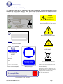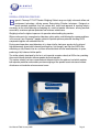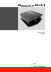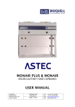
1
BIGNEAT
____________________________________________________________________
Containm ent Tec hnology
BIGNEAT LIMITED
User Manual
PO W D ER W EIG H IN G R AN G E
GUIDE TO INSTALLATION,
OPERATION, SAFETY & MAINTENANCE
™
CHEMCAP - POWDER WEIGHING CABINETS
PRODUCT RANGE: F3 XIT D MODEL
BIGNEAT LIMITED 4 & 5 PIPER’S WOOD INDUSTRIAL PARK, WATERBERRY DRIVE, WATERLOOVILLE
HAMPSHIRE PO7 7XU UK
TEL. NO. +44 (023) 92 266400 FAX NO. +44 (023) 92 263373
EMAIL: [email protected] WEBSITE: www.bigneat.com
Manual No & Rev: F3001/UK Rev 1 May 2011
© Bigneat Limited 2011
User Manual F3001 January 2010
Page 1
BIGNEAT
____________________________________________________________________
Containm ent Tec hnology
CONTENTS
Index
Title
i
About this manual
ii
Product Safety information
iii
Identification and labelling
4
iv
EC declaration of conformance
5
SECTION 1
Design & Operating principles
6
SECTION 2
General construction
7
F3 XIT D Performance Specification
8
Installation guidelines
9
SECTION 3
Page
3
site selection
airflows and pressure regimes
electrical connection
SECTION 4
Commissioning
10
setting airflow velocity
containment test
Figure 1 anemometer measurement points
SECTION 5
Operation
Operating the cabinet
SECTION 6
11
12
Safety Monitoring
changing the HEPA filter
13
electrical safety
cleaning
SECTION 7
Maintenance
SECTION 8
Re-examination and Testing
14-15
16
APPENDIX 1 COSHH Regulations
APPENDIX 2 Electrical schematic
User Manual F3001 January 2010
Page 2
BIGNEAT
____________________________________________________________________
Containm ent Tec hnology
I About this Manual
This manual is intended as a guide to the operation, servicing and maintenance of the product.
This manual’s descriptions do not describe the operational functionality of the final system into which this
product may be incorporated. Reference should be made to other applicable devices documentation.
___________________________________________________________________________________________________________________________________________________________________________________________________________________________________________________________________________________________
ii Safety Information
Hazards
During servicing and maintenance, this equipment can potentially cause danger through exposure to
used (contaminated) filters, the employment of high voltages1 and high speed rotating fans where
access panels are opened.
Failure to observe the recommendations in this manual will constitute a SAFETY OR ELECTRICAL SHOCK
HAZARD
Installation, Operation and Servicing
The equipment must be installed, operated and/or serviced as recommended in this manual, otherwise the
electrical protection and/or the airflow integrity of the cabinet could be compromised. Any such installation or
use will invalidate all guarantees and warranties.
Maintenance and repair
Repair, adjustment or maintenance with safety or normally fixed covers removed whilst enclosure is under
voltage should be avoided. Skilled personnel only, aware of the potential hazards involved, should carry out
these operations.
Environment
This product is intended for indoor use;
Temperature range: 50C to 400C
Humidity: Max RH 80% for temperatures up to 310C, decreasing linearly to 50% RH at 400C.
It is not designed or certified for use in a potentially explosive environment as defined in Atex Directive
94/9/EC.
Mains supply voltage fluctuations up to ± 10% of nominal voltage
Containment & Operator Protection
Safe, acceptable levels of hazardous substances containment, for operator protection can only be assured
whilst the cabinet is fully operating, developing correct airflow velocity under normal conditions. In the event of
a power failure, all substances under process should be removed from the enclosure (to a separate safe
environment), or separately sealed whilst within the enclosure, with all visors remaining closed.
Fire risk
Under normal conditions there are no direct sources of ignition within the working zone of the cabinet and no
intrinsic risk of fire or explosion during normal use.
The acrylic enclosure will provide a tolerable level of initial containment should a fire occur, (caused when fine
dry powders are ignited during a process initiated by the end-user).
The end-user must carry out adequate prior risk assessment to determine the potential hazards posed by all
processes to be undertaken.
1
defined in BS EN 61010: 2001 as voltages above 55 Volts r.m.s (78.0 V peak) 140 Volts DC
User Manual F3001 January 2010
Page 3
BIGNEAT
____________________________________________________________________
Containm ent Tec hnology
iii Product identification and labelling
The equipment is fitted with the self-adhesive label types shown below, which uniquely identifies product
validation and safety hazard warnings. These labels should not be removed, as the Quality Assurance
acceptance Tests, Validation, and CE Mark compliance may be affected.
Danger
Disconnect the
Mains supply before
Removing this cover
Warning Label type1
Risk of Electric Shock if covers removed
Rating Label & CE Marking
Warning Label type 2
Refer to manual for safety information
BIGNEAT
Containment Technology
Service Record Label
Warning Label type 3
Electrical Hazard
TESTED
FOR ELECTRICAL
SAFETY
SERIAL NO:
TESTED BY:
DATE:
Waste Electrical and Electronic Equipment
(WEEE) Symbol
Stop machine before
removing guards
RETEST BY:
The use of the WEEE Symbol indicates that this product
cannot be treated as household waste at end-of-life.
TESTED IN ACCORDANCE WITH
BIGNEAT SPECIFICATION SOP 14.0
Tested for electrical safety label
Restriction of the use of certain Hazardous
Substances (RoHS)
Warning Label type 4
This cabinet is fitted with
Chemcap™ Filter
for use with particulates
HP
Bigneat Ltd. has taken all reasonable steps to ensure
that the product does not contain any or more than the
permitted maximum concentrations of the six
designated restricted hazardous substances namely,
Pb, Hg, VI, PBB, PBDE and Cd
SHOULD YOU HAVE ANY QUESTIONS CALL +44 (0)23 92 266400
FILTER IDENTITY LABEL (EXAMPLE)
User Manual: F3001Revision C
Page 4
BIGNEAT
____________________________________________________________________
Containm ent Tec hnology
EC DECLARATION OF CONFORMITY
Certificate Serial No: XP-002
Product Description:
This is to certify that the:
CHEMCAP™ DUCTLESS FILTRATION SERIES
POWDER WEIGHING & HANDLING SAFETY CABINETS
F3-XIT MODEL: D
comply with the essential health and safety requirements of the following EC Directives
i.
Safety: All of the relevant provisions of the Machinery Directive 2006/42/EC, 1st Edition, by the
application of the following harmonised standards:
BS EN 61010-1:2001 safety requirements for electrical equipment for measurement, control
and laboratory use.
BS EN ISO 12100-2:2003 Safety of Machinery-Basic concepts-general
ii.
CE Mark: The product conforms with the relevant provisions of Council Directive 93/68/EEC, the
CE Marking Directive.
iii.
EMC: The product conforms with the relevant provisions of Council Directive 2004/108/EC relating to
Electro-magnetic compatibility, by the application of the following EMC standards and applicable
reference standards:
BS EN 61326:2006 Electrical equipment for measurement, control and laboratory use. EMC
requirements.
Emissions: CISPR 11:2003 Class A , IEC 6100-3-2:2000, IEC 6100-3-2: 2002
Immunity: IEC 61000-4-2:2001, IEC 61000-4-3:2002, IEC 61000-4-4:2004,IEC 61000-45:2001
IEC 61000-4-6:2003, IEC 61000-4-11:2004
iv.
v.
The product conforms with the requirements of: BS7989:2001 specification for recirculating filtration fume
cupboards.
Product Operating Voltage: 230V ± 10% 50/60 Hz, Single Phase
Name: Michael Tanner
Position: Quality & Compliance Manager Signature:
Date: January 2010
Being the responsible person appointed by the manufacturer, established in the EC, and employed by:
Bigneat Ltd 4 & 5 Pipers Wood Industrial Park, Waterberry Drive, Waterlooville, Hampshire PO7 7XU U.K
Technical file No TF-XP 001 specific to these products is retained at BIGNEAT LIMITED
Phone: +44 (0)23 92 266400
User Manual F3001 January 2010
Fax: +44 (0)23 92 263373
E-mail: [email protected]
Page 5
BIGNEAT
____________________________________________________________________
Containm ent Tec hnology
1.0
DESIGN & OPERATING PRINCIPLES
B
igneat’s Chemcap™ F3 XIT Powder Weighing Cabinet range use highly advanced airflow and
containment technology, utilising proven Recirculating Filtration techniques. Designed as
bench mounted equipment, they are custom built, tested and approved to exacting industry
standards, for the safe dispensing and weighing of a variety of powder substances, offering excellent
accessibility, maximum operator protection and minimum maintenance.
Weighing is often the highest exposure risk operation when handling dry powders.
When used as part of a comprehensive laboratory safety routine, and following the recommendations
in this manual, your Chemcap™ powder cabinet will provide optimum protection handling OHC3
compounds together with extended filter life.
During normal operation, room/laboratory air is drawn into the front open aperture by the internal
high-performance dynamically balanced centrifugal fan, first through a pre-filter then HEPA filter,
exhausting as fully filtered clean air, and then recirculated back into the room/laboratory air space,
producing a fully balanced airflow profile.
The airflow velocity developed by the fan is set to provide a capture velocity of 0.35 m/sec, providing
the essential barrier between airborne powder dust and operator.
This capture velocity has been researched and determined to be the optimum level which provides
both operator protection and enables precision weighing of fine powder based substances without
disturbance or introduction of measurement errors.
User Manual F3001 January 2010
Page 6
BIGNEAT
____________________________________________________________________
Containm ent Tec hnology
SECTION 2.
GENERAL CONSTRUCTION
The cabinet consists of an epoxy coated mild steel fan & filter housing, containing the fan, variable
fan speed controller, HEPA filter and pre-filters, mounted on top of an acrylic enclosure.
The dynamically balanced, centrifugal fan is adjusted using the internal speed controller and enables
the air velocity developing through the front working aperture to be set precisely.
Re-circulating technology using HEPA filtration, removes harmful powders or fumes making them
ideal for a number of weighing applications.
A removable steel grille supports the Pre-filter media below the main HEPA filter within the fan/filter
housing.
The Fan & Filter housing is a fully welded mild steel fabrication, finished in a chemical resistant, ovenbaked epoxy powder coating. It is designed to locate directly onto the acrylic enclosure below without
fasteners.
The lower enclosure is constructed from flame resistant, safe-edged, 8mm clear acrylic-material.
Factory Acceptance Testing
Comprehensive Factory Acceptance Tests and Product Quality Audits have been applied to the
cabinet at Bigneat’s premises and include the following mandatory standards:
• Electrical Safety Tests; Bigneat Standard SOP 14.0
• Airflow velocity calibration; Bigneat Standard SOP 3.0
• Filter integrity tests using DOP method: Bigneat Standard SOP 9.0
User Manual F3001 January 2010
Page 7
BIGNEAT
____________________________________________________________________
Containm ent Tec hnology
2.1
F3-XIT-D Performance Specification
Effective dimensions:
Cabinet Width: 600 mm ext.
Cabinet Depth: 520 mm ext.
Cabinet Height: 650 mm ext.
Cabinet weight: Approx. 25Kgs
Face Velocity: Preset at 0.35 metres per second
Filtration system: 1. Synthetic Pre-filter Efficiency: 95% @ 5µ m particle size
2. Main HEPA filter Efficiency: 99.997% @ 0.3 µ m particle size
Fan type: EBM RG 160-28/565 centrifugal
Cabinet Noise Level: < 50dBA at 1 metre
Power consumption: 96 watts, maximum current: 0.5A
Power requirements: 230 Volts ± 10%, 50/60 Hz, Single Phase 5A
Compliance standards: a) BS 7989: 2001, b) EN61010: 2001
User Manual F3001 January 2010
Page 8
BIGNEAT
____________________________________________________________________
Containm ent Tec hnology
SECTION 3.0
INSTALLATION GUIDELINES
Site Selection
Powder cabinets must be placed well away from open windows, doors and other sources of
disruptive air changes, which may affect safe and consistent operation.
With regard to space and general ventilation, the average laboratory or workroom will normally
be adequate, there should naturally be ample space around the cabinet to move and operate
conveniently.
Warning! The pre-filter should never be obstructed in any way.
General installation recommendations
Ambient temperature: from 5ºC to 40ºC
Relative humidity: RH < 80% at 31ºC
Noise levels
The noise generated by the fan and resulting air movement will not rise above measured limits
during normal operation, with the folding access door closed.
Cleanliness Standard
The site should be maintained as clean and dust free as possible, since the cleaner the
environment the more efficient the filtration will be and help to reduce pre-filter maintenance
costs. Using a damp cloth, clean the exterior surfaces of the cabinet, regularly, particularly the
front and side surfaces, to remove accumulated dust.
Note: Do not use solvent-based chemicals to clean the acrylic panels, particularly on a regular
basis as this may promote stress cracking of the acrylic material.
Airflows and pressure regimes
To avoid air currents and pressure fluctuations in the laboratory or work room affecting the
performance of the safety cabinet, position it well away from any disruptive air changes such
as open windows, air conditioning vents, doors etc.
Room air velocity should not exceed 0.25m/s.
Electrical connections
The cabinet must be earthed:
Connect the cabinet to an adjacent, switched ~230V, 13 amp socket outlet, using the mains
lead supplied.
User Manual F3001 January 2010
Page 9
BIGNEAT
____________________________________________________________________
Containm ent Tec hnology
SECTION 4.0
COMMISSIONING
After connecting the mains lead to the electrical supply, operate the fan by pressing the green
pushbutton switch to the ON position. The green indicating lamp will now be illuminated and
the fan running.
4.1 Setting airflow velocity
Test equipment needed:
Calibrated Ø 100 mm rotating-vane anemometer with accuracy: 0.25 to 5 m/s = ± 5% of
reading/± 0.05 m/s @ 20ºC or better.
Preparation:
For the following commissioning procedures the cabinet should be empty of all equipment and
the upper folding acrylic door closed. Ensure that both blanking caps are fitted.
The fan blower should be allowed to run for several minutes in order to stabilise, after which
measurements and adjustments should be carried out as follows:
The fan speed has been pre-set during factory acceptance testing to provide an average face
velocity of [0.35] m/sec, however, adjustments may be necessary to accommodate local air
regimes, and final filter loading as follows:
• Allow the fan to stabilise for at least 10 minutes before taking measurements
• Measure the inflow face velocity at the open aperture using a suitably ranged and
calibrated 100 Ø rotary-vane type anemometer. Readings should be taken over a 30
second interval noting the highest and lowest values at four notional ‘grid points’ in front
of the aperture of the acrylic front door. Record these readings to determine the
average (See Figure 1).
4.2
Containment test
As it is not generally practical to carry out on-site SF6 containment testing of ductless
recirculatory cabinets owing to the need to provide a temporary exhaust system, the airflow
profile at the face of the cabinet can be evaluated by smoke visualisation testing.
User Manual: F3001Revision C
Page 10
BIGNEAT
____________________________________________________________________
Containm ent Tec hnology
FIGURE 1
Anemometer measurement points to determine
average face velocity at the open front aperture
1
150
80mm
2
3
4
approx
80 mm approx
80 mm approx
ANEMOMETER
User Manual: F3001Revision C
Page 11
BIGNEAT
____________________________________________________________________
Containm ent Tec hnology
SECTION 5.0
OPERATION
5.1
Operating the Safety cabinet
With the cabinet connected to the mains supply, Press the green (Fan start) pushbutton to ON
(illuminated). The fan speed will eventually stabilise at the level preset during commissioning.
Allow sufficient time for the airflow velocity to stabilise throughout the interior before carrying
out any weighing process.
Protection and containment
The level of protection afforded by the cabinet is affected by the manner in which it is used.
Good laboratory practice should be followed and include the following guidelines:
• Adequate planning and understanding the function of the safety cabinet.
• Keep your face outside of the plane of the enclosure aperture and remain alert to
changes in airflow (indicated by the airflow alarm)
• Do not make abrupt arm or hand motions in or out of the aperture, or walk quickly past
the cabinet. These will cause disturbance to the airflow reducing the containment
efficiency.
• Do not lift the folding front panel except where necessary for apparatus set up. The
folding upper front panel should always be closed during use of the cabinet. This
ensures the airflow velocity remains at the preset safe level. In addition, it serves as a
protective shield and helps protect the user from explosive or highly reactive materials. *
• Keep the front aperture free from obstruction by apparatus or containers.
• Limit the amount of any chemicals stored within the cabinet during procedures where
possible
• Do not switch off the cabinet during weighing operations
• Allow 15 minutes after operations cease before switching off the fan.
*This product is not designed or certified for use in a potentially explosive environment as defined in Atex Directive
94/9/EC. also, it should not be relied upon to provide safe containment in the event of fire caused by the process
atmosphere.
User Manual F3001 January 2010
Page 12
BIGNEAT
____________________________________________________________________
Containm ent Tec hnology
SECTION 6.3SAFETY MONITORING
Air Velocity Adjustment
The inward airflow velocity will progressively reduce due to the gradual contamination and
‘blocking effect’ of the filter. When ‘blocking’ begins to affect airflow velocity, a small increase
of the fan speed can compensate and provide continued effective usage; however, this must
not be left for too long a period once detected, since ‘breakthrough’ of particles may occur.
The required re-adjustment in airflow may also be beyond the remaining speed controller
range so the filter must be replaced.
6.4 Changing the HEPA Filter
The contaminated Main filter should be removed and sealed in a heavy-duty waste sack for
correct disposal. See section 7.0.
Safety Warning! Protective overalls, gloves, facemask and safety glasses should be worn
throughout these procedures.
6.5 Electrical Safety
This powder Cabinet has been tested as an electrical Class 1 appliance, and must continue to
meet the requirements of the UK Electricity at Work Regulations 1989. The correct fuse must
be fitted to the mains plug and this with other exposed parts of the electrical system should be
examined frequently for signs of damage. There should be regular inspections carried out by a
‘competent’ person and must include earth bonding and insulation tests. Records should be
kept of these inspections.
6.6 Cleaning
Cabinet enclosures should be cleaned (and disinfected if this is applicable) frequently and
regularly. Clean the enclosure with the unit running to promote first-level dilution.
Wipers should always be of the highest quality non-shedding type suitable for clean room use.
Daily
Using a damp cloth, clean the exterior surfaces of the cabinet, regularly, particularly the front
and side surfaces, to remove accumulated dust.
Weekly
Thoroughly surface decontaminate the work surface using 70% ethanol (or other approved
disinfectant)
The recommended method of cleaning the acrylic surfaces is by damp wiping with diluted
detergent and water.
Note: Do not use solvent-based cleaning solutions as this may promote stress cracking of the
acrylic panels.
User Manual F3001 January 2010
Page 13
BIGNEAT
____________________________________________________________________
Containm ent Tec hnology
SECTION 7.0MAINTENANCE
Regular maintenance is essential to the proper functioning of this powder cabinet and we
recommend entrusting this to a service department or external company who are technically
competent and equipped with calibrated instruments.
They will also be familiar with the current UK COSHH regulations demanded by both
Government and industry and will maintain a service record for each unit.
7.1 Changing the filters
Pre-filter: The pre-filter requires changing regularly. This ensures proper airflow, extends the
life of the HEPA filter and is undoubtedly the most important of all maintenance operations.
The frequency of changing depends on the environment. Regular visual inspection should be
carried out. A pre-filter that has turned dark grey needs changing. Studies have shown that
pre-filters should be changed twice a year.
7.2 Procedure
Safety Warning!
Suitable Personal Protective Equipment (PPE), which may include protective overalls, gloves,
facemask and safety glasses, should be worn throughout these procedures.
Place a clean plastic sheet or cover and waste sacks close to the cabinet in advance,
• With the fan running, first clean the inside of the enclosure and remove any hazardous
materials.
• Switch Off the Fan and remove mains lead from the supply!
• After cleaning the inside of the enclosure, lift the fan housing completely clear of the
acrylic enclosure below. Place onto the clean plastic sheet or cover upside down.
• Carefully remove the HEPA filter (spray the ‘contaminated face’ with (hair) lacquer
before removing to seal the surface). (See Note 1)
•
Place promptly inside an appropriately labelled hazardous waste sack, double-bagged.
• Remove the Pre-filter from the filter tray below and place into a second waste sack.
Seal the sack.
• Using a HEPA filtered vacuum cleaner, remove all traces of powder dust from within
the fan housing
User Manual F3001 January 2010
Page 14
BIGNEAT
____________________________________________________________________
Containm ent Tec hnology
7.2 contd..
• Refit a new HEPA filter (reverse of initial removal) check correct placement within
frame,
• Install a new pre-filter in reverse order; making sure it is pushed to the very back of the
tray.
•
Replace the fan housing onto the acrylic enclosure. Reconnect the mains lead.
Note 1. The ‘stiction’ effect of the neoprene seals may make initial removal of the HEPA filter difficult,
however, avoid applying extreme movements to remove it from its position otherwise particles may be
loosened and contaminate the local area.
User Manual: F3001Revision C
Page 15
BIGNEAT
____________________________________________________________________
Containm ent Tec hnology
SECTION 8.0
Re-examination and Testing
This Cabinet must be thoroughly examined, serviced and tested at least every 12 months to
meet current COSHH regulations (which stipulate a maximum 14 month interval) and should
include the following checks:
•
•
•
•
Average (inflow) airflow velocity and efficiency.
Smoke visualisation test of inflow air velocity pattern
Filter saturation, seal and enclosure integrity using DOP method
Fan motor noise or vibration
• Electrical safety inspection
Bigneat’s own Service Department has many years experience in Fume and Particulate Extraction
maintenance. We would be pleased to quote for a Service Contract.
User Manual F3001 January 2010
Page 16
BIGNEAT
____________________________________________________________________
Containm ent Tec hnology
APPENDIX 1
NOTES ON UK COSHH REGULATIONS
1.
The “Control of Substances Hazardous to Health” (COSHH) 2002 regulations.
2.
The regulations are the UK implementation of the EEC Council directive 80/1107/EEC.
3.
The regulations require an employer to protect his employees and any other people (whether working
for him or not) from hazardous substances.
4.
A hazardous substance is defined as:a)
A substance, which is on the list of hazardous substances as defined by the classification,
Packaging and Labelling Regulations 1984 (b).
b)
A substance for which an Occupational Exposure Limit (OEL) value exists. This list is similar
to US threshold Limit value Levels (TLV).
c)
A microorganism, which creates a health hazard.
d)
Dust at a substantial concentration in air.
e)
Any substance, which creates a hazard to health, similar to the hazards, created by the
substances in a-d.
Note that paragraph 4e is a “catch-all” section.
5.
The employer is responsible for assessing the risk to an employee.
6.
The employer must prevent or control the exposure of an employee to hazardous substances.
7.
The control of exposure “shall be secured by measures other than the provision of personal protective
equipment”. This means the fumes must be contained, rather than providing protective suits and
masks to staff.
8.
OEL values must not be exceeded.
9.
The employer must ensure that safety equipment is properly used.
10.
The employee must use safety equipment provided correctly.
11.
The employer must maintain safety equipment in good working order. In particular:a)
Exhaust ventilation equipment must be examined every 14 months.
b)
Other safety equipment must be examined at “suitable intervals”.
c)
Records of checks, tests and repairs must be kept for 5 years.
12.
Monitoring of exposure to hazardous substances must occur “in accordance with a suitable
procedure”. Records of results must be kept for 5 years for general monitoring, and for 30 years
when they relate to a specific employee.
13.
Regular medical checks are required when working with certain listed substances, or where an
identifiable disease is associated with a certain substance.
14.
An employer must provide suitable instruction and training to employees regarding risks of
substances and precautions to be taken.
15.
Certain other regulations take precedence, such as Control of Lead at Work, Control of Asbestos at
Work, radioactive, explosive or flammable regulations, Mines and Quarries Act, and medical treatment
regulations.
User Manual F3001 January 2010
Page 17
BIGNEAT
APPENDIX 2
____________________________________________________________________
Containm ent Technology
ELECTRICAL SCHEMATIC
ILLUMINATED
FAN SWITCH
IEC FUSED
SOCKET
Brown
3.15A
Blue
3.15A
LIVE
0.75mm2 red wire
LOAD
L
SUPPLY
230 VOLTS
SINGLE PHASE
50/60 Hz
Gn/Yel
2
0.75mm green/yellow wire
PE
IEC to UK plug
mains lead-2M
User Manual F3001 January 2010
Page 18
FAN TYPE RGS -160 -28/565
0.75mm2 red wire
0.75mm2 black wire
0.75mm2 black wire
N
E
FAN SPEED
CONTROL
VAC2-1 RFI
BIGNEAT
____________________________________________________________________
Containm ent Tec hnology
ISO 9001
REGISTERE D FI RM
INTERNATIONAL
ACCREDITATION BOA RD
Certif icate No.GB200 13 86
Registration No . 004 4/1
Printed and Published by
Bigneat Limited
4 & 5 PIPERS WOOD INDUSTRIAL PARK
WATERBERRY DRIVE
WATERLOOVILLE
HAMPSHIRE PO7 7XU
UNITED KINGDOM
TEL: +44 (0) 23 9226 6400 FAX: +44 (0) 23 9226 3373
E-MAIL: [email protected]
WWW.BIGNEAT.COM
User Manual F3001 January 2010
Page 19