1
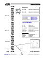
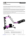
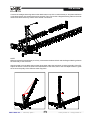
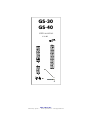
GS-30
GS-40
USER MANUAL
V.11.06
PRO LIFTS S.L.
Valencia, Spain - www.prolifts.es - [email protected]
GS series, Truss-tower / ground support.
Manufacturer
PRO LIFTS S.L.
Calle 7 - Pol. Ind. Picassent
E-46220 Picassent
CE CERTIFICACTION, EUROPEAN PRODUCT
This user manual is property of PRO LIFTS S.L. Any reproduction of this manual, by any means is strictly prohibited.
GS series
CONTENTS
Safety notes
4
1. Introduction
- General information GS series
6
- Components GS-30 / GS-40
7
2. Tower assembly
- When Tower basis sit on top of the stage
9
- When Tower base on the floor below the stage
10
- The GS helper system
11
3. Tower disassembly
- How to proceed
Guarantee
13
14
GS series
SAFETY NOTES
1. For your safety and protection, YOU MUST read these instructions completely before using the
equipment, and keep them for future reference.
2. Carefully observe all warnings, precautions and instructions when using this equipment. All personnel
using this equipment should be trained for the proper and safe use of this equipment
3. First identify all separate components and types of truss to be used, ensure that you fully understand this
manual before you start using any of these parts, components and trusses.
4. Never use truss parts or vital components such as wire ropes (or chains), that show visual damage,
deformation or have any other reason to doubt the safe functioning within the
system. Make sure you check each item before each use.
5. Unless optional outriggers are used the system to be lifted MUST be a four (4) sided box or rectangle and
include four (4) towers, one in each corner.
6. The total load of each tower, including hoist, must not exceed the SWL stated in the specifications of the
product.
7. Check the building site for obvious hazardous objects such as power lines. Keep a safe distance of at least
8m from those in any possible direction of sway in the wind, or the distance as specified in the national or
local codes or regulations for safe operation of mobile cranes. Always check the planned tower-building
activity with the power-company.
8. Check the building site for obstacles such as lamp-posts, trees or tree-tops, overhead piping, in house
constructions, or any other higher objects that might hamper erection of the towers or might endanger it when
swaying in the wind or so.
9. Measure the area where the tower needs to be and make sure there is enough room for all components
including the outriggers. (the free and cleared building site for each tower, needs to be approx 3.5m wide,
7.5m deep and a minimum of 8m high)
10. The ground, floor, or stage on which the towers will stand must be capable of withstanding the substantial
point load imposed by these towers.
11. A square of 20mm plywood should be placed under each tower base in order to avoid damage to the floor
surface and to help disperse the load.
12. The towers must be assembled with the diagonals forming a continuous pattern. The sides of the tower
with the diagonals should be parallel with the longest span of truss (If the rig is 5 sections wide and 3 sections
deep the diagonals will be on the upstage and downstage faces of the tower).
13. Towers must be vertical before any weight is applied, or the strength and stability will be impaired.
14. Tower sections must be examined regularly for signs of damage. Care should be taken when handling
tower sections. Inspect all components before using them for visual wear & tear, deformation, damage or any
other shortcomings. NEVER use parts or components that are not visually correct or you suspect have been
subject to other damage.
PRO LIFTS S.L. - Valencia, Spain -
4
www.prolifts.es - [email protected]
GS series
15. The truss pins with clips, or truss bolts must be checked every time the towers are used.
16. Once a load has been applied to the tower, the screw jacks should be adjusted so that each is carrying
an equal load. Use a wrench and adjust by hand until equal pressure is achieved.
17. When rigging the chain hoist it is essential there are no twists in the chain. The hoist should be rigged on
the downstage or offstage side of the sleeve block (depending on alignment of the head block) so the moving
chain will not rub against the structure.
18. All hoists must run simultaneously so the rig always remains level.
19. The motor must be rigged in such a way as to keep the motor and hook below the top of the sleeve block
or plate. This enables the truss to be raised to the top of the tower.
20. Once the rig is at show trim a safety should be fitted. A 2000 - 3000 Kg truck ratchet strap or spanset is
suitable. This must be fitted tightly around the top of the roller beam and the sleeve block.
21. A full understanding of the principals employed in the systems design is necessary before use. It is
important that the weight and distribution of the entire load is known, and that experienced personnel, who
are able to evaluate the circumstances, are used to operate this equipment.
PRO LIFTS S.L. - Valencia, Spain -
5
www.prolifts.es - [email protected]
GS series
GENERAL INFORMATION GS TOWERS
The GS Towers are ground supports with truss square section of 30cm (GS-30) or 40cm (GS-40) with a steel
lifting sleeveblock operated by electric chain motor. Cushioned by the vertical tower structure it moves via nylon
pulleys.
The truss structure is 6082-T6 aluminium and is constructed with tubular sections, 50mm external diameter
with 3.5mm thickness for the main lifting sections and 26mm exterior diameter with 3.5mm thickness for
triangular bars. The fixing between sections is carried out with perforated plaques of the same material and
fixed with M-16/8.8 screws.
The GS Towers GS-30 and GS-40 are set on a solid steel base with twisting wheels for the transport and 4
stabiliser legs adjustable depending on work surface. The lifting is done by means of an aluminum cart that
slides vertically through nylon guided pulleys on the corners of the vertical structure. Its Fixed plates with
screws do the coupling between de sections of the lift.
TECHNICAL SPECIFICATIONS
GS-30
GS-40
MAXIMUM HEIGHT:
12m
15m
MAXIMUM LOAD:
2000Kg
3000kg
ELEVATION:
HOIST
HOIST
TRUSS SECTION:
30 x 30cm
40 x 40cm
ALUMINIUM ALLOY:
6082 T6
6082 T6
MAIN TUBES:
50 x 3,5mm
50 x 3,5mm
BRACES:
26 x 3,5mm
26 x 3,5mm
COMPONENTS GS-30 FOR 9 / 12 m
COMPONENTS GS-40 FOR 9 / 15 m
GS-30 /9m
GS-30 /12m
GS-40 /9m
GS-40 /15m
1 x GS-30C
2 x GS30-TR3
1 x GS30-TR2B
1 x GS30-TR1B
1 x GS-30B
1 x Sleeveblock
1 x GS-30C
3 x GS30-TR3
1 x GS30-TR2B
1 x GS30-TR1B
1 x GS-30B
1 x Sleeveblock
1 x GS-40C
2 x GS-40/TR3
1 x GS-40/TR2B
1 x GS-40/TR1B
1 x GS-40B
1 x Sleeveblock
1 x GS-40C
4 x GS-40/TR3
1 x GS-40/TR2B
1 x GS-40/TR1B
1 x GS-40B
1 x Sleeveblock
You can configure intermediate heights.
PRO LIFTS S.L. - Valencia, Spain -
6
You can configure intermediate heights.
www.prolifts.es - [email protected]
GS series
GS-30C
GS30-TR3
SLEEVE BLOCK
GS-30/40E3
GS-30/40E4
3 way block for 40x40cm truss
4 way block for 40x40cm truss
GS-30/52E3
GS-30/52E4
3 way block for 52x52cm truss
4 way block for 52x52cm truss
GS-30/76E3
GS-30/76E4
3 way block for 76x52cm truss
4 way block for 76x52cm truss
GS-30 can be used with the following Truss:
Square 40x40 cm
Square 52x52 cm
Rectangular 76x52 cm
Folded 76x52 cm
VMB truss TR-C40
VMB truss TR-P52
VMB truss TR-P76
VMB truss TR-P76P
LIST OF COMPONENTS
GS-30C
GS30-TR3
GS30-TR2B
GS30-TR1B
GS-30B
Top with pulleys
Square truss 3 m main tube 3’5 mm
Square truss 2 m main tube 3’5 mm
Square truss 1 m main tube 3’5 mm
Base
GS-30P
GS-30T
GS30-TR2
GS30-TR1
GS30-TR08
GS30-TR08B
Stabiliser leg
Tight piece for leg
Square truss 2 m main tube 3’5 mm
Square truss 1 m main tube 3’5 mm
Sq. truss 0.8 m main tube 3’5 mm
Square truss GS30-TR08 with hinge
Other accessories
SE-GS-12
SA-G1
1/2C-52M
SM-40A
SM-52A
Ground support assembly helper
Hoist support plaque
Hoist bracket
Top support
Top support
GS30-TR3
GS30-TR2B
GS30-TR1B
GS-30T ( optional )
Hinge system-easy assembly
GS-30B
GS-30P ( optional )
PRO LIFTS S.L. - Valencia, Spain -
7
GS-30 COMPONENTS
www.prolifts.es - [email protected]
GS series
GS-40C
SLEEVE BLOCK
GS-40/TR3
GS-40/52E3
GS-40/52E4
3 ways block for 52x52cm truss
4 ways block for 52x52cm truss
GS-40/76E3
GS-40/76E4
3 ways block for 76x52cm truss
4 ways block for 76x52cm truss
GS-40 can be used with the following Truss:
Square 52x52 cm
Folded 52x52 cm
Rectangular 76x52 cm
Folded 76x52 cm
VMB truss TR-P52
VMB truss TR-P52P
VMB truss TR-P76
VMB truss TR-P76P
LIST OF COMPONENTS:
GS-40/TR3
GS-40C
GS-40B
GS-40P
GS-40T
GS-40/TR3
GS-40/TR2B
GS-40/TR1B
GS40-TR1
GS40-TR2
GS40-TR08B
GS40-TR08
Top with pulleys
Base
Stabiliser leg
Tight piece for leg
Square truss 3m
Square truss 2m with hinge
Square truss 1m with hinge
Square truss 1m
Square truss 2m
Square truss 0.8m with hinge
Square truss 0.8m
Other accessories
SE-GS-12
SA-G1
1/2C-52M
SM-52A
Ground support assembly helper
Hoist support plaque
Hoist bracket
Top support
GS-40/TR2B
GS-40/TR1B
GS-40T
GS-40B
PRO LIFTS S.L. - Valencia, Spain -
Hinge system for easy assembly
GS-40P
8
GS-40 COMPONENTS
www.prolifts.es - [email protected]
GS series
TOWER ASSEMBLY WHEN TOWER BASIS SIT ON TOP OF THE STAGE SURFACE
1. Place the bases on the stage with the screw jacks completely off the floor. Make certain the stage deck is
capable of supporting the weight. Connect the first truss unit to the base.
2. Lift a sleeve block and slide it down over the truss unit.
3. Lay out and connect the entire lighting truss.
4. Position the rig on the stage.
5. Assemble remaining tower sections and the roller beams to desired height. Be sure the diagonals are on
the same side and form a continuous pattern.
6. Attach a rigging rope (recommended length 30 meters to the head block and run it over the top of the tower
truss. If using a Ground Support Assembly Helper SE-GS12 refer to instructions on this manual and continue
with step 13 after securing the Hinge pins, bolts or camlocks.
PRO LIFTS S.L. - Valencia, Spain -
9
www.prolifts.es - [email protected]
GS series
7. Check that entire rig is assembled and ALL truss pins with r clips or truss bolts are secured correctly.
8. Check the vertical range for the tower erection path and the vertical path that the horizontal truss will follow
during erection. Make sure nothing can obstruct a proper and safe working order.
9. Raise tower by using 4 or 5 of the crew pulling on the rope plus 5 or 6 pushing up on the tower. Take care
not to pull the tower over when it reaches its vertical position.
10. While continuing to hold tension on the rope insert and lock truss bolts in the hinge section.
11. After the pins, or truss bolts are secure one person, equipped with a proper safety harness, should climb
the tower, untie the rope and run it over the roller beam wheels so the loose end reaches the stage.
12. Attach the hook of the hoist chain to the rope and pull the chain up the tower over the rollers and back
down to the sleeve block. (The hoist should be on the onstage or upstage side of the sleeve block with the
hook on the chain on the offstage or downstage side). The person on top of the tower will need to feed the
hook over the rollers and check to see that there are NO TWISTS in the chain.
13. Attach hoist to the bottom tubes of the truss with spansets or truss flying point. The chain hook and hoist
should be rigged so they ride below the top of the truss. Be sure the hook of the hoist is carrying the load and
that the hoist housing is not wedged between the gusset plates. Always check to be sure there are no twists
in chain.
14. Screw down the jacks on the base until each of the four has an equal load. Check for level in both
upstage/downstage and on/off stage directions using at least an 45 cm level. Do not apply any load to the
motor until the jacks have been screwed down. Continue to the next tower repeating steps 6 to 13.
15. After all towers have been erected and levelled, electrical cables should be run for the chain hoists.
16. Then ‘bump’ each motor until there is equal tension on all chains. When all personnel have been cleared
raise the rig to a working height. HOISTS MUST ALWAYS BE RUN TOGETHER. IF FOR ANY REASON
ONE SHOULD STOP THEY SHOULD ALL BE STOPPED.
17. Finish setting up the rig. Be sure no cables will be pinched between the sleeve block and roller beam. All
cables near the sleeve blocks should be tied to insure they can’t become tangled.
18. When the rig has been raised to «show trim» a safety MUST be put on each tower. This should be a
spanset running from one side of the sleeve block, over the roller beam to the opposite side of the sleeve
block. This must be fitted tightly around the top of the roller beam and the sleeve block. Any slack could result
in the safety being ineffective.
TOWER ASSEMBLY WHEN TOWER BASE ON THE FLOOR BELOW THE STAGE
1. Place the tower base on the floor under the stage.
2. Having measured the distance from the house floor to stage, join the appropriate length of tower to the
hinge section so that the hinge will fall a few cm above the height of the sleeve block.
3. With the hinge section on top, insert the pre-assembled tower and hinge section through the sleeve block
and connect it to the base. Be sure the diagonals are properly located and form a continuous pattern.
4. Continue assembly as explained before «when tower bases sit on top of the stage surface».
PRO LIFTS S.L. - Valencia, Spain -
10
www.prolifts.es - [email protected]
GS series
THE GS HELPER SYSTEM
The Ground Support Assembly Helper SE-GS12 is developed as a practical element for the erection of the
GS-Tower masts. It is a portable construction that can be put on in a very flexible way.
The SE-GS12 can erect masts up to 12 m of height. The use of the SE-GS12 is independent from the type of
truss that is used in the main grid.
The SE-GS12 is constructed as a main frame and several loose tubes, which can be connected as a triangular shaped construction by means of a pen/fork attachment. This triangular construction is placed on the
sleeve block on the one end and on the truss at the other and is fixed with the help of ratchet straps.
The main frame has a pulley at the top, through which the chain of the hoist is guided. By attaching the hoist
to the base section and the hook of the chain to the mast the tower can be erected easily. A job which
otherwise has to be done by at least 3 or 4 people and a rope.
The SE-GS12 can easily be transported from the one tower to the next; just loosen the ratchet straps and fix
them again at the desired place.
p2
p1
p3
The GS-Helper SE-GS12 is composed of:
p1 Vertical frame
p2 Diagonal bracing
p3 Alicraft connectors
PRO LIFTS S.L. - Valencia, Spain -
Ladder frame with pulley block for GS-Helper SE.GS12
Tube to connect the vertical frame to the truss
Special alicraft piece to connect the diagonal bracing
11
www.prolifts.es - [email protected]
GS series
Connect the 2 diagonal bracing tubes to the attachment on top of the vertical frame p1. And place this frame
on the sleeve block of the tower that is to be erected. Then connect the 2 diagonal bracing tubes to the truss
linked to the sleeve block by means of the alicraft connections.
NOTE
Make sure that the vertical frame p1 is firmly connected to the sleeve block and the diagonal bracing tubes to
the truss body of the GS tower.
After the tower is connected at the two lower hinge parts; place the hoist chain over the top pulley of the GSHelper SE-GS12. Connect the hoist to the base section of the tower, NOT to the GS-Helper. And then guide
the chain to the pulley of the GS truss tower Top piece.
PRO LIFTS S.L. - Valencia, Spain -
12
www.prolifts.es - [email protected]
GS series
Switch the hoist that will be used to lift the tower on and bring the chain to tension, act similar when a lever
hoist is used. When the chain is tight, start lifting the tower.
Lift the tower slowly and gradually, but without interruptions, by means of the hoist. Keep a constant movement
and do NOT switch the hoist on and off. The use of a speed control is advised. Never stop the hoist during the
lifting process.
NOTE
High dynamic loading will result in dangerous overloading of various components. Without the use of a
variable speed control the top section will reach high angle speeds as a result of the fixed speed of the
hoist. The use of a speed control is therefore highly preferred.
When the tower is almost erect you can easily push the tower in its end position. Place the locking pins in the
hinge parts. Then release the tension on the hoist. Release the tension on the chain and remove the GSHelper
TOWER DISASSEMBLY
1. Climb each tower (with proper safety harness) and release the safety lock off.
2. Ensure all hoists run together and lower the rig to working height.
3. Raise lamp bars and remove any equipment that will stop the rig from being lowered to the stage deck.
Do not remove motor cables.
4. When everything and everyone is clear, lower the rig to the deck.
5. Clear the rig of all other equipment and cables. DO NOT DISCONNECT ANY CAMLOCS, PINS, OR
TRUSS BOLTS, ANYWHERE ON THE RIG !
6. Have someone climb (with proper safety harness) each tower and lower chains from towers using the
rigging rope, the person will need to guide and feed hook over the rollers (take care not to get fingers
between the chain and rollers). If using a Ground Support Assembly Helper SE-GS12 refer to the
instructions for lowering towers.
7. After the chain has been lowered the rope should be tied to the top of tower and the person should
return to the stage.
8. With a crew standing ready on the rope and base of the tower remove the truss pins,camlocs or truss
bolts that allow hinge to open. ONLY DISCONNECT THE HINGE CAMLOCS, PINS, OR TRUSS BOLTS !
!
9. Disconnect the tower from the hinge section and place on the floor. Continue to the next tower repeating
steps 6 - 10 until all towers have been lowered. ALL Towers MUST be lowered before any truss is
disassembled.
PRO LIFTS S.L. - Valencia, Spain -
13
www.prolifts.es - [email protected]
GS series
GUARANTEE
VMB’s products are guaranteed against every kind of manufacturing fault 2 year after the date of sale. When
products are under guarantee, the repairing and the free supplying of the device parts in order to correct any
kind of defect are guaranteed by VMB. In the case that the product could not be returned to the factory for
checking and repairing, VMB would supply all the necessary parts.
VMB is not responsible for any damage or defect caused during the transport or caused by an undue or
improper handling y a non-authorized person during the life of this guarantee.
All our products undergo rigorous tests and quality controls. We guarantee the characteristics described here
within and their quality against any fabrication defect.
The user loses all warranty rights if he incorporates or carries out any modification to the product, if he uses
it outside of the stated safe working loads or does not secure the system properly using all the pins in their
corresponding holes.
For any question regarding the product, the user must quote the model and serial number.
PRO LIFTS S.L.
Pol. Ind. Picassent - Calle 7, final - 46220 Picassent (VALENCIA) Spain
www.prolifts.es - [email protected]