1
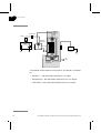
Optional Column
Selection Valve
User Manual
71-5029-20
Important user information
Terms and Conditions of Sale
All users must read this entire manual to fully
understand the safe use of ÄKTAdesign instruments.
Unless otherwise agreed in writing, all goods and
services are sold subject to the terms and conditions of
sale of the company within the Amersham Biosciences
group which supplies them. A copy of these terms and
conditions is available on request.
WARNING!
The Warning sign highlights an instruction
that must be strictly followed in order to avoid
personal injury. Be sure not to proceed until
the instructions are clearly understood and all
stated conditions are met.
Caution!
The Caution sign is used to call attention to instructions
or conditions that must be followed to avoid damage to
the product or other equipment. Be sure not to proceed
until the instructions are clearly understood and all
stated conditions are met.
Note
The Note sign is used to indicate information important
for trouble-free and optimal use of the product.
Should you have any comments on this product, we will
be pleased to receive them at:
Amersham Biosciences AB
SE-751 84 Uppsala
Sweden
Trademarks
Drop Design, ÄKTA, ÄKTAFPLC, ÄKTApurifier,
ÄKTAbasic and UNICORN are trademarks of
Amersham Biosciences Limited.
Amersham and Amersham Biosciences are trademarks
of Amersham plc.
Office Addresses
Amersham Biosciences AB
CE Certification
This product meets all requirements of applicable CEdirectives. A copy of the corresponding Declaration of
Conformity is available on request.
The CE symbol and corresponding declaration of
conformity is valid for the instrument when it is:
–
used as a stand-alone unit, or
–
connected to other CE-marked Amersham
Biosciences instruments, or
–
connected to other products recommended or
described in this manual, and
–
used in the same state as it was delivered from
Amersham Biosciences except for alterations
described in this manual.
WARNING!
This is a Class A product. In a domestic environment
this product may cause radio interference in which case
the user may be required to take adequate measures.
SE-751 84 Uppsala
Sweden
Amersham Biosciences Limited
Pollards Wood
Nightingales Lane
Chalfont St. Giles
Bucks HP8 4SP
UK
Amersham Biosciences Corp.
800 Centennial Avenue
P.O. Box 1327
Piscataway, N.J. 08855
USA
Amersham Biosciences Europe GmbH
Munzinger Strasse 9
D-79111 Freiburg
Germany
Amersham Biosciences K.K.
Sanken Building
3-25-1 Hyakunincho, Shinjuku-ku
Tokyo 169–0073
Japan
© Copyright Amersham Biosciences 2003
- All rights reserved
Contents
Contents
1 Introduction .................................................. 7
1.1 General ....................................................................................... 7
1.2 Optional column selection valve ................................................... 7
2 Safety .......................................................... 9
2.1 Safety .......................................................................................... 9
3 Unpacking .................................................. 10
4 Pre-requisites ............................................. 11
5 Mounting of brackets .................................. 12
5.1 Valve ID ..................................................................................... 13
5.2 UniNet Connection .................................................................... 14
6 Installation ................................................. 15
6.1 Preparation for use .................................................................... 15
7 Operation ................................................... 17
7.1 Preparing for operation .............................................................. 17
7.2 ÄKTAfplc/ÄKTApurifier/ÄKTAbasic - UNICORN 3.2 - 3.21 .......... 18
7.3 ÄKTAfplc/ÄKTApurifier/ÄKTAbasic - UNICORN 4.0 - 4.12 .......... 20
ÄKTAdesign Optional Column Selection Valve User Manual 71-5029-20 Edition AA
v
Contents
vi
ÄKTAdesign Optional Column Selection Valve User Manual 71-5029-20 Edition AA
1
Introduction
1 Introduction
1.1 General
ÄKTAdesign standard system configurations can be changed to
optional configurations. This flexibility in ÄKTAdesign system
strategies allows the user to enhance already used purification methods
and also to develop new, more complex methods.
When optional equipment is connected to a standard chromatographic
system, new sets of instructions to control the optional equipment
become accessible for the user.
Optional configurations are selected, installed and put into operation
by the user. An optional configuration consists of both hardware
components and software instructions.
Optional configurations are monitored and controlled via methods run
by the UNICORN™ control system in the same way as ÄKTAdesign
standard system configurations.
1.2 Optional column selection valve
Column and media screening can be automated by adding two
motorized valves onto the system. This setup allows:
•
Automated method optimization and multi-step purification as
well as column selection.
•
Up to eight columns can be connected onto the system. Column
performance can be easily compared while changing conditions in
a run. The setup is time saving and increases reproducibility of the
results.
•
Preset protocols will prevent over-pressurization and protect
columns from breaking.
ÄKTAdesign Optional Column Selection Valve User Manual 71-5029-20 Edition AA
7
1
Introduction
Column
Selection
Valve
(V2)
On-line filter
Mixer
2
3
17
7
6
Injection
Valve (V1)
B
Restrictor
2
6
34 5
Pump A Pump B
A
18
4 5
W2
Fraction
Collector
W1
W3
2
3
18
4 5
Column
Selection
Valve (V3)
7
6
UV
COND
The optional column selection valve (code no. 18-1108-41) is available
for:
• ÄKTAFPLC™ with UNICORN Software 3.2 or higher
• ÄKTApurifier™ with UNICORN Software 3.21 AA or higher
•
8
ÄKTAbasic™ with UNICORN Software 3.21 AA or higher
ÄKTAdesign Optional Column Selection Valve User Manual 71-5029-20 Edition AA
2
Safety
2 Safety
2.1 Safety
•
The components are designed for indoor use only.
•
Do not use in a dusty atmosphere or close to spraying water.
•
Operate in accordance with local safety instructions.
WARNING! When using hazardous chemicals, all suitable protective
measures, such as protective glasses, must be taken.
WARNING! Ensure that the entire chromatographic system has been
flushed thoroughly with distilled water before removing any capillaries
or components.
WARNING! Always disconnect the power supply before attempting to
replace any item on the equipment during maintenance.
WARNING! If there is a risk that large volumes of spilt liquid may
penetrate the casing of the equipment and come into contact with the
electrical components, immediately switch off the chromatographic
system and contact an authorized service technician.
CAUTION! Make sure that the ÄKTAdesign instrument is switched off
before installing the optional components. The mains power to the
ÄKTAdesign instrument must be switched OFF before disconnecting
or connecting the UniNet-1 and UniNet-2 cables.
ÄKTAdesign Optional Column Selection Valve User Manual 71-5029-20 Edition AA
9
3
Unpacking
3 Unpacking
Unpack the optional components and check against the supplied
packing list. Inspect the items for obvious damage that may have
occurred during transportation.
CAUTION! Read the following information carefully, as well as all the
additional instructions supplied with the components, to ensure that
the ÄKTAdesign optional equipment is installed correctly.
10
ÄKTAdesign Optional Column Selection Valve User Manual 71-5029-20 Edition AA
4
Pre-requisites
4 Pre-requisites
The general procedures for creating and editing methods are described
in the UNICORN User Manuals.
Note: The system configuration delay volume must be recalculated and
reset when the standard configuration after the UV flow cell is
changed.
ÄKTAFPLC, ÄKTApurifier and ÄKTAbasic respectively must be
installed and fully tested before the optional components are installed.
See the Installation Guide for your ÄKTAdesign chromatography
system.
WARNING! Ensure that the entire system has been flushed
thoroughly with distilled water before removing any capillaries or
components.
CAUTION! Make sure that the ÄKTAdesign instrument is switched off
before installing the optional components. The mains power to the
ÄKTAdesign instrument must be switched OFF before disconnecting
or connecting the UniNet-1 and UniNet-2 cables.
ÄKTAdesign Optional Column Selection Valve User Manual 71-5029-20 Edition AA
11
5
Mounting of brackets
5 Mounting of brackets
CAUTION! Make sure that the ÄKTAdesign instrument is switched off
before installing the optional components. The mains power to the
ÄKTAdesign instrument must be switched OFF before disconnecting
or connecting the UniNet-1 and UniNet-2 cables.
Optional equipment can be mounted on the system. When selecting
mounting location for the optional equipment it is important to choose
a location which minimize the length of the capillaries used to connect
the optional components to the rest of the system.
Many components that are attached to the mounting rails uses a snapin bracket. The bracket is supplied separately with the component and
needs to be fitted as shown below before the component can be
attached.
2. Fit the attached
mounting bracket with
the two screws
Inserting components
1. Loosen the
two screws
Removing components
12
ÄKTAdesign Optional Column Selection Valve User Manual 71-5029-20 Edition AA
5
Mounting of brackets
5.1 Valve ID
2
IV/PV -908
The column selection valve has a unique ID code which identifies it to
the UNICORN control system at system start-up. This ID code should
be checked before installation.
The ID code for the column selection valve and the corresponding
instructions used in UNICORN to control it are as follows:
Valve function
ID code
Valve type
Instruction in
UNICORN
Column selection
2
PV-908
Column selection
3
PV-908
ColumnPosition
(combined instruction
controlling both valves)
Components are connected to the UNICORN control system using
either UniNet-1 or UniNet-2 cables. Both the UniNet-1 and the
UniNet-2 data communication chain in standard configuration is
routed from the rear of the system pump via their respective
components to the last component in the chain where it is terminated
with a plug.
Note: When Pump P-960 is used, it is always installed as the last
component in the UniNet-2 chain. Since the pump has an
internal termination, no termination plug is needed.
ÄKTAdesign Optional Column Selection Valve User Manual 71-5029-20 Edition AA
13
5
Mounting of brackets
5.2 UniNet Connection
Both the UniNet-1 and the UniNet-2 chain can be interrupted
anywhere between the system pump and the termination plug to
interconnect the optional components in the chain. The termination
plug can be moved to the last component (furthest away from the
system pump), if motivated by cable routing considerations.
Optical
Unit
Conductivity
Flow Cell
Analogue
out 0-1 V
To P C
co n t r o lle r b o a r d
UniNet 1
pH-Ground pH-Probe
Mains
Lamp
Voltage
Frequency
100-200 V- 50-60 Hz
Power, max
30 VA
Pressure
Analogue out 0-1 V
Remote
UniNet 2
U n iN e t - 2
ch a in
UniNet 1
Frac ti on
c ol l ec tor
Mains output
Leakage current, max
3,5 mA
P C r u n n in g U N I C OR N
Mains
Voltage
100-200 V-
Frequency Power, max Fuse
50-60 Hz
600 VA
T 6,3 AL
WARNING! For continued protection against
risk of fire, replace only woth fuse
of the specified type and current ratings
5
4
9
3
8
2
7
1
6
Term i nati on
pl ug
U n iN e t - 1
ch a in
Use the attached UniNet-2 cables to connect the valves to the
UniNet-2 communication link. The valves can be connected anywhere
between the system pump and the termination plug.
Check that all capillary and electrical connections are carried out
correctly.
14
ÄKTAdesign Optional Column Selection Valve User Manual 71-5029-20 Edition AA
6
Installation
6 Installation
6.1 Preparation for use
To start your ÄKTAdesign optional configuration system:
1
Switch on the ÄKTAdesign instrument with the mains switch
located at the front left on the system base.
2
Check that the computer and printer are switched on.
3
Log in (see ÄKTAFPLC-, ÄKTApurifier-, or ÄKTAbasic Making
your first runs respectively).
4
In UNICORN Main Menu, select Administration:System Setup.
5
Select System and then click Edit. Click Component....
6
From the Component list, select the optional column valve you have
installed by checking the box, or by clicking ADD.
7
Click OK twice and then Close.
8
Mark the two PV-908 valves 2 and 3. Check that the ID code switch
is set to 2 and 3 respectively.
ÄKTAdesign Optional Column Selection Valve User Manual 71-5029-20 Edition AA
15
6
Installation
9
Mount the brackets and attach the two valves to the system rack
(see chapter 5).
10 Cut and mount the new i.d. 0.50 mm or i.d. 0.75 mm capillaries.
Mount one capillary between port 1 on column valve 2 and port 1
column valve 3. This is the column bypass position used as default
position for the valves in UNICORN.
16
ÄKTAdesign Optional Column Selection Valve User Manual 71-5029-20 Edition AA
7
Operation
7 Operation
7.1 Preparing for operation
1
A connected valve is automatically recognized by UNICORN at
system start-up. Check that the added valve is indicated in the flow
scheme in UNICORN.
2
Verify that the valve is functioning properly by issuing manual
commands from UNICORN as follows:
• In System Control, select Manual:FlowPath.
• Select instruction ColumnPosition.
• Select and execute a new position for the valve. View the valve
in the flow scheme panel to confirm that the position change has
occurred.
• Manually run the system pump with distilled water at a flow rate
of approximately 2 ml/min, and check that water is coming out
from the valve port selected.
Valve panel
• Connect a capillary to the valve port selected on column valve 2
for stop. Connect this capillary to the same port on column
valve 3. Check that water is coming out from the center port of
column valve 3.
ÄKTAdesign Optional Column Selection Valve User Manual 71-5029-20 Edition AA
17
7
Operation
7.2 ÄKTAFPLC/ÄKTApurifier/ÄKTAbasic - UNICORN 3.2 - 3.21
7.2.1 Using the column selection function in a run
The column selection valves are designated ColumnValves in the flow
scheme, and V2_ColPos and V3_ColPos in the run data windows. To use
the column selection valves in a method, proceed as follows:
1
In the Main Menu, select File:New:Method to create a new method.
Select System:, Technique:, Template: and For column:. Click OK.
2
Select View:Text instructions to display the text instruction editor.
Double-click on the instruction block where you want to add the
column selection instruction, e.g. Start_Conditions_zz. Highlight the
instruction below to insert the valve instruction.
Click here to define a
variable name for the
instruction parameter
18
3
Click the Flowpath radio button.
4
From the Instructions list, select ColumnPosition. The valve
instruction parameter Position allows you to change all eight
positions of the column selection valves synchronously.
ÄKTAdesign Optional Column Selection Valve User Manual 71-5029-20 Edition AA
7
Operation
5
Define a variable name for the instruction parameters, e.g.
ColumnValves_Pos. This variable allows you to synchronously
control the position of the column valves to the position you want.
6
Click OK. The defined variable is inserted in the method.
7
Return to the Variables page by selecting View:Run setup to set the
variable ColumnValves_Pos to the desired position.
8
Save the method.
ÄKTAdesign Optional Column Selection Valve User Manual 71-5029-20 Edition AA
19
7
Operation
7.3 ÄKTAFPLC/ÄKTApurifier/ÄKTAbasic - UNICORN 4.0 - 4.12
7.3.1 Using the column selection function in a run
To use a valve in a method, select the desired valve options in the
Method Wizard when creating the new method.
The column selection valves are designated ColumnValves in the flow
scheme, and V2_ColPos and V3_ColPos in the run data window.
20
ÄKTAdesign Optional Column Selection Valve User Manual 71-5029-20 Edition AA
TC information, Uppsala. Printed in Sweden by TK i Uppsala AB