1
«Sigrand» LLC
SHDSL modem
«Sigrand SG-17B»
User’s manual
v. 3.5
Novosibirsk
2014
© «Sigrand», 2005 – 2014
All the trademarks, signs and copyrights associated with the items referred
to in this document belong to the relevant right-holders.
ТУ 6665-017-77565155-2007
2
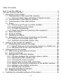
Table of Contents
How to use this «Manual…» ....................................................................... 5
The use of fonts in the text .......................................................................... 6
1. Description of the modem ..................................................................... 7
1.1. Characteristics of the linear DSL interface ...................................... 8
1.1.1. Communication range and bitrate of Sigrand modem ............... 9
1.2. Characteristics of the Ethernet interface ....................................... 10
1.3. Characteristics of the USB interface ............................................. 10
1.4. Power ........................................................................................... 11
1.4.1. Remote power Power-over-DSL (PoDSL) .............................. 12
1.4.2. Local powering of the modem................................................. 12
1.4.3. Through-line powering ............................................................ 12
1.4.4. Power-over-Ethernet powering of the equipment .................... 13
1.5. Other information .......................................................................... 14
1.6. Scope of delivery .......................................................................... 15
1.7. Operating conditions ..................................................................... 15
1.8. Appearance and functions of indicators and sockets..................... 15
1.8.1. Indicators and sockets indoor case......................................... 16
1.8.2. Indicators and sockets outdoor case ...................................... 19
2. Setting up the modem for operation .................................................... 20
2.1. Connecting the modem to the cable ............................................. 20
2.1.1. Specific features of connecting the modem to a PoDSL line ... 20
2.1.2. Requirements for the communication line ............................... 21
3. Management of the modem ................................................................ 22
3.1. How to link-up and set-up a terminal ............................................. 22
3.2. Control commands ....................................................................... 22
3.3. Management of the DSL interface ................................................ 24
3.3.1. Choosing between the «master»/«slave» options ................... 24
3.3.2. Adjusting the DSL interface rate ............................................. 24
3.3.3. Choosing the linear encryption ............................................... 25
3.3.4. Adjusting the auxiliary DSL parameters. ................................. 27
3.3.5. Review of the current configuration of the SHDSL interface.... 27
3.3.6. Statistics of the SHDSL connection ........................................ 28
3.3.7. Resetting the connection ........................................................ 29
3.4. Adjusting the Ethernet interface .................................................... 29
3.5. PoDSL and PoE modes ................................................................ 29
4. Updating the embedded software of the modem ................................. 30
3
Guaranty and warranties ........................................................................... 33
WARRANTY CARD .................................................................................. 34
Appendix А ............................................................................................... 35
4
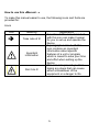
How to use this «Manual…»
To make this manual easier to use, the following icons and fonts are
provided for:
Icons
Icon
Meaning
Take note of it!
Important
information
Don’t do it!
Explanation
A section of this manual marked
with this icon can make it easier
for you to set up and operate the
device
A paragraph marked with this
icon contains an important
information about specific
features of a unit or program
which is meant to save your time
and effort when setting up the
device
This icon is to prevent you from
taking any steps that can cause
either a breakdown of the
equipment or a danger to life
5
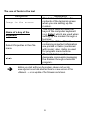
The use of fonts in the text
Designation
Image in the screen
Name of a key of the
keyboard
Select Properties in the File
menu
stat
Explanation
This font is used to show the
contents of the terminal screen
when you are setting up the
modem.
This font is used to name the
keys of the computer keyboard
(e.g. Enter) which are used when
setting up the modem through a
terminal
Fragments of the «Manual …»
containing important information
are printed in italics (combined
with icons); also, italics is used
for program menu buttons.
The bold font is used to
designate commands managing
the modem through a terminal
program.
Before you start setting up the modem, please visit our site
www.sigrand.ru and see whether there is a new version of this
«Manual …» or an update of the firmware and drivers.
6
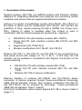
1. Description of the modem
Sigrand modems «SG-17B» are SНDSL-modems with Ethernet interface
designed for integrating distributed local networks and connecting remote
computers and devices that are supplied with Ethernet interface.
Feature of a number of modification modem (SG-17B-261, SG-17B-161) is
the ability to obtain, and for modifications (SG-17B-441, SG-17B-351) the
possibility of filing, remote powering through a SHDSL line (Power-overDSL). Feature to obtain is available when the modem is used in
combination with the following equipment produced by « Sigrand »:
•
•
•
•
DSLAM SG-17S (with interface modules MS-17H4P2);
Router SG-17R (with interface modules MR-17H1P2 and MR17H2P2);
Regenerators SG-17E2P-SLG;
Modems modifications SG-17B-441, SG-17B-351;
Modems SG-17B-111, SG-17B-121, and SG-17B-141 are powered from a
local power source with voltage 3.3, 12, or 48 V - in this case, SG-17B
modems can be operated in combination with Sigrand non-function of the
remote powering:
•
•
•
DSLAM SG-17S (with interface modules MS-17H4);
Router SG-17R (with interface modules MR-17H1 and MR17H2);
Modems SG-17B of various modifications.
Ethernet interface of modems SG-17B-541 and SG-17B-261 allows
connection of devices powered through Power-over-Ethernet technology
(IEEE 802.3af standard, Class2). Also modems modification SG-17B-151
and SG-17B-351 can be powered by technology Power-over-Ethernet
(IEEE 802.3af standard, Class1, Class3).
A full list of modification series modem Sigrand SG-17B is shown in table 2
(page 11).
7
The interface of SHDSL modem complies with ITU-T G.991.2.bis version
(the version of 2005) and uses the TCPAM – Trellis-Coded Pulse Amplitude
Modulation encoding set for data transfer.
The modem is equipped with the following interfaces:
•
•
•
one SHDSL interface (ITU-T G.991.2.bis standard) operating in
the bitrate range 192-15296 Kb per second;.
one Ethernet interface 10/100Mb (IEEE 802.3) with the options of
automatic rate adjustment and auto-sensing MDI/MDI-X;
one USB interface for managing the modem.
1.1. Characteristics of the linear DSL interface
Connection type
The number of wires in the communication
line
Type of the cable
Linear code
Input and output resistance, Ohm
Bitrate range of data transfer, Kb per second
Step of bitrate change, Kb per second
Type of communication
Mode of data transfer
Packet format
Checksum
Type of socket
Breakdown voltage of the galvanic isolation
transformer, not less than, V
Arrester response voltage (differential), V
Breakdown voltage of the surge arrester
(phase-locked), V
8
point-to-point
2 (one pair)
ТПП, КСПП, UTP
TCPAM
135
192-15296
64
full-duplex
synchronous, packeted
HDLC
CRC32
2EDGR-5.08-03P
1500
30
350
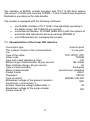
1.1.1. Communication range and bitrate of Sigrand modems
Brief information on communication range and bitrate of Sigrand SG-17B
modems is given in Table 1. The results were obtained with the length of
lines providing the value of Bit Error Rate (BER) equal or less than 10-7. The
specified value of communication range is proved experimentally at the test
communication line of Sigrand Laboratory. The complete Table of bitrates is
shown at www.sigrand.com. The actual results shown at a real
communication line may differ from the specified values because of
possible diversities in the parameters of the lines.
Table 1
Bitrate
(Kb per second)
Linear code
Parameter
15296
ТСРАМ128
10240
ТСРАМ64
7168
TCPAM64
5696
TCPAM32
3072
TCPAM16
2304
TCPAM16
1024
TCPAM16
512
TCPAM16
Length (km)
R (Ohm)
Length (km)
R (Ohm)
Length (km)
R (Ohm)
Length (km)
R (Ohm)
Length (km)
R (Ohm)
Length (km)
R (Ohm)
Length (km)
R (Ohm)
Length (km)
R (Ohm)
Cable
ТПП100-0.5
0,6
150
1,8
324
2.8
504
3.4
612
5
900
5.4
972
7.8
1404
9.0
1800
The actual bitrate range may happen to be limited with 5.7 Mb per second in
case the modems are used in combination with some types of interfaces
issued before 2009 which have bitrate limitations.
9
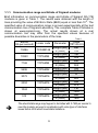
1.2. Characteristics of the Ethernet interface
Type of the interface
The number of ports
Bitrate, Mb per second
Mode of operation
Compatibility
Auto-sensing MDI/MDI-X
10/100 Base-T
1
10/100
Half- and full-duplex
ANSI/IEEE Std 802.3
Available
1.3. Characteristics of the USB interface
Type of the interface
The number of ports
USB
1
USB interface at the modem operate in a USB Serial Port mode
USB Serial Port settings:
Bitrate, b per second
Protocol
Flow control
115 200 or 9600
8-N-1
absent
The bitrate of USB Serial Port depends on the version of the embedded
software. By default, software supporting bitrate of 115200 b per second
is installed.
10
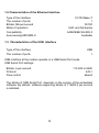
1.4. Power
Modem series Sigrand SG-17B has modification with different type of power
– ~220B, PoE receipt and delivery, a wide range of DC voltage: 12V, 24V,
48V and modification of the issuing and receiving the remote powering
through a DSL line (Table 2).
Table 2
*
*
*
48
Class 2
*
*
Class 2
*
Class 1
48
Class 3
*
*
mounting on
DIN-rail
48 (до 10 Вт)
execution
PoDSL (240V DC)
PoE
120…240V DC
(PoDSL)
48V DC (PoE)
18…72V DC
output voltage
sealed IP66
SG-17B-111
SG-17B-121
SG-17B-141
SG-17B-541
SG-17B-161
SG-17B-261
SG-17B-151
SG-17B-441
SG-17B-351
220V AC
modification
9,2…15 V DC
type of modem power
option
option
option
option
option
option
option
option
option
option
SG-17B-IPE where:
I – interface (1 - one Ethernet an one SHDSL; 2 – one Ethernet PoE
output and one SHDSL PoDSL input; 3 – one Ethernet PoE input and
one SHDSL PoDSL output; 4 – one Ethernet PoE output and one
SHDSL).
P – power (1 – 3,3V; 2 – 12V; 3 – 24V; 4 – 48V; 5 – 48V PoE; 6 – 240V
PoDSL).
E – enclosure (1 – indoor case; 2 – IP66 case; 4 – indoor case with
mounting on DIN-rail; 5 – IP66 case with mounting on DIN-rail;)
With a maximum load of PoDSL (17W) for SG-17B-351 modem power
consumption is about 20 W, which corresponds to the class of consumption
PoE +
11
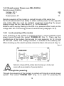
1.4.1. Remote power Power-over-DSL (PoDSL)
Remote power (PoDSL):
Voltage, DC V
Current, mA
Output power, W
240
70
17
Remote powering of the modem is carried through a DSL signal line.
For the modems which has ability to obtain remote power, on the opposite
side of the DSL line must be installed equipment supporting the power
supply through the line. (see Section 1, p.7 of this Manual).
Modems which supply feeding to the DSL line, powered either locally on the
voltage 48V DC or technology Power-Over-Ethernet (paragraph 1.4.4).
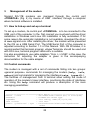
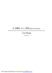
1.4.2. Local powering of the modem
Local powering of the modem is carried out from a local constant-current
power source through the socket “POWER IN” (Fig. 1). There are four
modifications of the modem that provide for local powering: for 12, 24 and
48 Volt and ~220V. The mating connector is included in the delivery set.
When hooking up, the electric polarity should be taken into account (Fig. 1).
Figure 1
Failure to comply with the polarity when hooking up a local power
source will cause actuation of power protection.
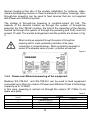
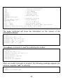
1.4.3. Through-line powering
Through-line powering of the modem is carried out through a remote power
system. The socket “POWER OUT” (Fig. 2) is used for powering the
12
devices located at the site of the modem installation, for instance, videocamera backlighting devices or thermo-elements of outdoor housings. Also,
through-line powering can be used to feed devices that are not supplied
with Power-over-Ethernet system.
The voltage of through-line powering is constant-current 48 Volt. The
capacity of the devices hooked up through the system of through-line
powering (for SG-17B-261 modem, the total of the capacities of the devices
hooked up through the system of through-line powering and РоЕ) must not
exceed 10 watt. The socket arrangement and the polarity are shown in Fig.
3.
When hooking up equipment through the system of through-line
powering need to make a preliminary calculation of the power
consumption of connected devices. When connected to equipment in
excess of the allowable values of power - protection will overload.
Figure 2
1.4.4. Power-over-Ethernet powering of the equipment
Modems SG-17B-541 and SG-17B-261 can be used to feed equipment
connected up to them by means of Power-over-Ethernet Class 2 technology
(capacity up to 10 Watt).
In this case, powering is carried out through the version “B” (Table 3) via
spare wire pairs.
Table 3
Contacts of the ETHERNET
socket
1
2
3
4
Function
DATA
Tranceive DATA+
Tranceive DATAReceive DATA+
POWER
Positive VPort (+U)
13
5
6
7
8
Positive VPort (+U)
Receive DATANegative VPort (-U)
Negative VPort (-U)
Modem modification SG-17B-151 is powered using PoE technology, power
consumption corresponds to the class of consumption – Class1 (up to 5
Watt, according to the standard IEEE 802.3af)
Modem modification SG-17B-351 also powered using PoE technology,
since this modification has the function of supply power over DSL line
PoDSL, power consumption is a modem for PoE corresponds to the class
of consumption - Сlass3 or PoE+ (to depend on the load PoDSL). At the
maximum consumption by PoDSL (17W), consumption modem through
PoE will be about 20 W, which corresponds to the class of consumption
PoE+.
Modem power SG-17B-151 and SG-17B-351 for option "A" and "B"
standard IEEE 802.3af.
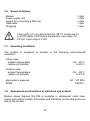
1.5. Other information
External dimensions of the modem case indoor:
• height, mm
• width, mm
• full length, mm
• length if the box, mm
Power consumption, W
44
93
63
62
Not more 3.6
External dimensions of the modem case outdoor:
• height, mm
• width, mm
• full length, mm
• length of the box, mm
Power consumption, W
44
93
115
88
Not more 3.6
14
1.6. Scope of delivery
Modem
Power supply unit
Socket for connecting a DSL line
USB cable
Wrapping
1 item
1 item
1 item
1 item
1 item
Power supply unit is only delivered with SG-17B-111 modems and it is
an AC/DC adapter of the following characteristics: input voltage 100240 VAC; output voltage 3.3 VDC.
1.7. Operating conditions
The modem is designed to operate in the following environmental
conditions:
Indoor case:
ambient temperature
relative air humidity
-35 .. 40º C
to 85 %
Outdoor case:
ambient temperature
relative air humidity
-35 .. 40º C
to 97 %
atmospheric pressure
MTBF
84 .. 107 KPa
45000 h.
1.8. Appearance and functions of indicators and sockets
Modem series Sigrand SG-17B is available in rectangular metal case,
indoor and outdoor sealed. All sockets and indicators are located at the one
side of the modem.
15
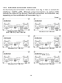
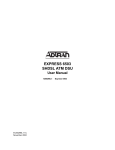
1.8.1. Indicators and sockets indoor case
On the front panel of modem in the indoor case Fig. 3 there is sockets for
interfaces: SHDSL, USB , Ethernet, ground connection, as well as LEDs
indicate the status of the device. Panel with connectors and indicators vary
depending on the modification of the modem Fig. 3.
Figure 3
Modems SG-17B-111,
SG-17B-121, SG-17B-141
Modem SG-17B-541
Modem SG-17B-161
Modem SG-17B-261
Modem SG-17B-151
Modem SG-17B-441
16
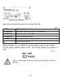
Modem SG-17B-351
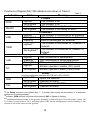
Appointment sockets and switch in modem SG-17B.
Table 4
LINE
DSL interface socket
ETHERNET
Ethernet interface socket 10/100Base-T
CONSOLE
Control port socket USB
POWER IN
Local powering socket
POWER OUT
Through-line powering socket
Ground connector
Switch "PoDSL" Fig. 4 controls the remote power supply to the line DSL.
For the supply remote power to the line should change the selector to
"ON".
Figure 4
Supply remote power to the line should be only after the connection
DSL line
17
Functions of Sigrand SG-17B indicators are shown in Table 5.
Table 5
Indicator
PWR
READY
LINK
100M
LINK
CO
State
Meaning
POWER
The modem is on
The modem is off
The modem is ready to work
The modem is not ready to work
ETHERNET
Lighted
The modem is connected to an Ethernet
Not Lighted
The modem is connected to an Ethernet
Flashing
Data is exchanged via Ethernet
The modem is connected to 100Base-TX
Lighted**
network
The modem is connected to 10Base-TX
Not Lighted**
network
DSL
Lighted
DSL connection is established
Flashing
DSL connection is being established
Not Lighted
DSL connection is not established
Lighted
Modem operate in master (CO) mode
Not Lighted
Modem operate in slave (CPE) mode
Lighted
Not Lighted
Lighted
Not Lighted*
PoDSL
( only for modification modems: SG-17B-441 и SG-17B-351 )
UNB
OVL
Lighted***
Not Lighted
Lighted
Not Lighted
Upset the balance
Operate normally
Overload source PoDSL
Operate normally
*If the Ready indicator is not lighted after 1 – 2 minutes after turning on the modem, it is mean that
modem not is working properly.
**Indicator 100M relevant only when the indicator LINK is lighted or flashing.
***Unbalanced remote power to the ground. Normally on one wire plus 120 on the other - minus 120
V. If there is more bias of 30 V, indicator lights UNB. Cause misalignment may be leaking or the
closure of one of the wires on the "ground."
18
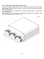
1.8.2. Indicators and sockets outdoor case
On the front panel of the modem in an outdoor case (Fig. 5) there are three
cable glands, which allows to make a connection to the interfaces SHDSL,
USB and Ethernet.
For the initial setup and connect the modem allowed delete a panel with
the cable glands.
The internal layout of connectors and indicators modem in an outdoor case,
fit the description given in section 1.8.1..
Figure 5
19
2.
Setting up the modem for operation
Sigrand SG-17B modems are set up through the serial control port
“Console” (interface USB) (Fig. 4).
It is provided for in the SHDSL standard that one of the linked modems acts
as the «master» modem for which all the communications parameters are
adjusted and the other acts as a «slave».
The state of a modem can be changed manually through the terminal
program of modem management (see Section 3.3.1).
2.1. Connecting the modem to the cable
Make sure that the allotted communication line does not have any foreign
electrical sources and is not hooked up to any foreign PABX equipment!
Failure to observe this rule may cause a breakdown both in the modems
and in the foreign equipment on the communication line!
Make sure that there are no thermal switches in the line. They will limit the
speed of modem operation.
2.1.1. Specific features of connecting the modem to a PoDSL line
With SG-17B-161 and SG-17B-261 modems, it is permissible to hook them
up to a DSL line with voltage already fed there from a Sigrand device:
•
SG-17S with MS-17H4P2 modules;
•
SG-17R with modules MR-17H1P2 or MR-17H2P2;
•
SG-17E2P-SLG.
When connecting the modem to a DSL line it is recommended that all the
equipment which is fed via through-line powering system or PoE should be
disconnected from the modem. This equipment is to be hooked up only
after the communication between the modem and the remote device is
established.
20
2.1.2. Requirements for the communication line
To ensure normal operation of the modems and the specified values of the
performance characteristics, the line must meet the following requirements:
•
•
•
•
•
The cable must have neither core-to-core bridges nor ground
leakages, or leakages to other conductors including those not
hooked up to anything. The line must not have branches.
Cores of a multi-pair cable must be taken from the same pair.
Parallel connection of several pairs (for instance, in order to
reduce the active resistance) is not permissible.
Failure to meet the above requirements may cause degradation
of the characteristics or even complete disability of the line.
Using
modems
in
either
aerial
or
combined
(underground+aerial) lines is forbidden.
Warranty will become null for the modems operated at aerial or combined
(underground+aerial) lines.
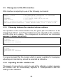
After you have made sure that the communication line meets the above
requirements, take the following steps:
• Place the RJ-45 plug on the cable, according to (Fig. 7). Modem
Sigrand SG-17B uses only one pair of wires, pins 4 and 5, the
other pins are not used..
• Connect the cable socket to the DSL socket of the modem.
Figure 7
socket connector
plug connector
21
3.
Management of the modem
Sigrand SG-17B modems are managed through the control port
«CONSOLE» (Fig. 4) by means of USB interface, through a computer
where terminal software is installed.
3.1. How to link-up and set-up a terminal
To set up a modem, its control port «CONSOLE» is to be connected to the
USB port of the computer. In the first connect you must wait until the driver
installation in Windows and Linux OS installation is fully automated. If for
some reason the automatic installation is not available, download the driver
at www.sigrand.com. After installing the driver, the modem will be presented
to the OS as a USB Serial Port. The USB Serial Port of the computer is
adjusted according to Section 1.3 of this Manual. With OS Windows, it is
recommended that terminal program «HyperTerminal» should be used and
with OS Linux, terminal program «Minicom» is suitable.
It is also acceptable to use cable adapters “Com <–> USB”; in this case, the
instruction for adjusting the adapter is given in the accompanying
documentation for the cable adapter.
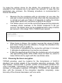
3.2. Control commands
The modem is managed with a set of commands falling into two groups:
«general purpose» commands for managing the modem (help, info,
reboot) and commands for managing the interfaces (rate, tcpam etc.).
The facilities of management from a terminal allow setting the mode of
operation of the modem’s linear interface, monitoring the state of interfaces
etc. Using the help command will produce a description of the main
managing possibilities:
> help
******************************Help menu********************************
master | slave
- set modem mode: master(CO) or slave(CPE)
annexA|B
- G.SHDSL.bis Annex type
tcpamXXX
- line coding, XXX={16,32,64,128}
rate <value>
- line rate
plesio | plesio-ref | sync - Plesiochronous/Plesio-Ref/Synchronous
modes
22
pbo-normal|pbo-forced <val> - Power Backoff mode, <val> - value in dB
cfg
- Inquiry configuration
stat
- Inquiry statistic
info
- Info modems
reboot
- Reboot modems
retrain
- Retrain links
default
- Default settings
ETHERNET settings:
eth
- Ethernet settings
eth <argument list>
- Setup ethernet
Argument list:
100 | 10
- 100 or 10 Mbit/s
full | half
- Full or Half duplex
auto | /auto
- Enable or Disable Auto negotiation
Examples: "eth 100 full", "eth auto", "eth /auto"
***********************************************************************
The info command will show the information on the version of the
embedded software:
> info
Sigrand SG-17BT v. 1.0
Firmware MC: SG-17BT v.1.0
Firmware IDC: v1.1_1.4.18
Firmware SDFE: v11.158.003
Firmware IAP: v1.0 UART
>
The reboot command is used for restarting the modem:
> reboot
Sigrand SG-17BT v.1.0
Firmware version: SG-17BT v.1.0
Initialization.....
Initialization complete
Configuration......
Configuration complete
When an invalid command is entered, the following message appears (for
instance, suppose “sdf” is entered):
> sdf
Command not found: sdf
>
23
3.3. Management of the DSL interface
DSL interface is adjusting by use of the following commands:
master | slave
annexA|B
tcpamXXX
rate <value>
plesio | plesio-ref|sync pbo-normal|pbo-forced<val>
set modem mode: master(CO) or slave(CPE)
G.SHDSL.bis Annex type
line coding, XXX={16,32,64,128}
line rate
Plesiochronous/Plesio-Ref/Synchronous modes
- Power Backoff mode, <val> - value in dB
3.3.1. Choosing between the «master»/«slave» options
For operation in the communication line, the given pair of modems is to be
arranged as follows: one of the modems is to be selected as the «master»
and the other as a «slave». The arrangement is performed via commands
master or slave, respectively.
> master
Configuration......
Configuration complete
>
> slave
Configuration......
Configuration complete
>
It is recommended that the modem which is easier available for managing,
adjusting and maintaining, should be selected as «Master».
3.3.2. Adjusting the DSL interface rate
The speed of connection is only to be set at the «Master» modem whereas
the «Slave» will be automatically adjusted in correspondence with the
settings of the «Master».
24
To make the optimal choice for the bitrate, the parameters of the line
intended for the modems are to be taken into account. In case the line
parameters are unknown, the following procedure is recommended to
choose the bitrate:
•
•
Measure the line resistance with an ohmmeter (at one side, the
wire pair is short-circuited and at the other side the measurement
is carried out) and use Table 2 of Appendix to define the bitrate
range within which the connection is going to be robust.
The bitrate value is set via the command rate and the parameter
<value> where <value> is the bitrate measured in Kb per
second. The bitrate value can be established with a step of 64 Kb
per second, in the range 192 to 15296 Kb per second.
> rate 15296
Configuration......
Configuration complete
>
•
•
•
When being a «Slave», the modem receives the values of bitrate
and linear coding from the «Master», through the standard G.hs
Preactivation (ITU-T G.994.1).
The process of establishing the connection will take 2-3 minutes.
3 attempts at establishing a connection are allowed.
If after the specified period of time the modems are not connected
(the light-emitting diode «DSL LINK» does not flash on), select a
lesser bitrate and try again with the new bitrate value.
3.3.3. Choosing the linear encryption
TCPAM encoding, used by modems for the transmission of G.991.2
standard, has several grades of the encryption algorithm complexity. With
high bitrates, versions with a greater number of modulation positions are
used (TCPAM64, TCPAM128) and with lower bitrates, modes with lesser
numbers of modulation positions (TCPAM16, TCPAM32) are applicable.
Also, with the increase of the encryption algorithm complexity, noise
Immunity of the channel decreases, and vice versa.
25
Therefore, when setting up the bitrate of the communication line, special
attention should be paid to the encryption algorithm TCPAM and, when
necessary, the linear coding should be altered in order to produce the best
possible results.
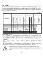
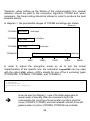
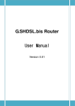
In diagram 1, the permissible ranges of TCPAM encodings are shown.
Diagram 1
TCPAM16
192 Kbps
TCPAM32
192 Kbps
TCPAM64
192 Kbps
3840 Kbps
6144 Kbps
8192 Kbps
5696 Kbps
TCPAM128
0
5000
15296 Kbps
10000
15000
20000
25000
In order to adjust the encryption mode so as to suit the actual
characteristics of the specific line, the command tcpamXXX can be used
with the option XXX, where «XXX» stands for one of the 4 encoding types
(TCPAM128, TCPAM64, TCPAM32, and TCPAM16).
> tcpam128
Configuration......
Configuration complete
>
As can be seen from Diagram 1, some of the bitrate ranges allow for
several modes of encoding. When the noise level is high in the
communication line, encodings of lesser number of positions should be
chosen (TCPAM16, TCPAM32); when the bandwidth is limited, those with
greater number of positions (TCPAM64, TCPAM128) are preferable.
26
When a linear encoding is entered for a bitrate which is outside the
permissible bitrate range, a message appears informing about encodings
recommended for this specific bitrate.
3.3.4. Adjusting the auxiliary DSL parameters.
The commands plesio, plesio-ref, sync are used to set up the
mode of synchronizing modems.
In case the communication route is formed of modems Sg-17B<->Sg-17B,
the mode of synchronization «sync» is recommended. Otherwise, modes
«plesio» or «plesio-ref» are preferable, the choice being determined
for each specific communication line empirically.
For a DSL line, it is possible to set the level of signal power backoff in
decibels (dB), by use of the command pbo-forced with the parameter
<val> where <val> is the level of power backoff within the range 0 to 30.
The command pbo-normal is used to establish the automatic mode of
signal power backoff in the communication line.
All the above commands can be either used separately or united
into a single line, for example:
> master annexA
tcpam128
rate 14080 sync pbo-normal
3.3.5. Review of the current configuration of the SHDSL interface
The command cfg can be used to review the current configuration of the
modem.
> cfg
Current configuration:
master Annex A TCPAM128 sync rate=15296 pbo-normal
>
27
3.3.6. Statistics of the SHDSL connection
To review the statistics of the connection, the command stat is used:
> stat
dsl_link: online
SNR_Margin 19dB, Loop Attenuation 1dB, pbo_Value 6
ES_count 0, SES_count 0, CRC_Anomaly_count 0, LOSWS_count 0,
UAS_count 0, Loss_count 0
•
•
•
•
SNR_Margin – signal/noise proportion in the line (dB);
Lopp Attenuation– level of signal attenuation in the line (dB);
Power Backoff – level of power backoff in the line (dB);
ES_count – the number of one-second intervals during which
either at least one CRC abnormality was detected, or more than
one LOSW errors;
•
SES_count – the number of one-second intervals during which
either at least 50 CRC abnormalities occurred or more than one
LOSW errors (for standard frame length, 50 CRC abnormalities
during one second correspond to 30% of invalid frames);
•
CRC_Anomaly_count – the number of CRC abnormalities
detected during the period of monitoring;
•
LOSWS_count – the number of one-second intervals during
which more than one LOSW errors were detected;
•
UAS_count – the number of one-second intervals during which
the SHDSL channel was not available. After a failure, the channel
is considered available when no SES occurred during 10
seconds. These 10 seconds are not counted as those during
which the channel was not available.
After each enquiry, the statistics is reset.
28
3.3.7. Resetting the connection
This command cuts the current DSL connection and initializes a new one.
Initialization of a new connection is defined by the option retrain:
> retrain
3.4. Adjusting the Ethernet interface
Sigrand SG-17B modems are equipped with a 10/100M Ethernet port, with
the option of auto-sensing MDI/MDI-X. By default, the Ethernet port is
arranged in the «auto» mode – with automatic speed/duplex adjusting.
If necessary, these parameters can be set manually:
ETHERNET settings:
eth
- Ethernet settings
eth <argument list>
- Setup ethernet
Argument list:
100 | 10
- 100 or 10 Mbit/s
full | half
- Full or Half duplex
auto | /auto
- Enable or Disable Auto negotiation
Examples: "eth 100 full", "eth auto", "eth /auto"
3.5. PoDSL and PoE modes
PoDSL and PoE powering is managed automatically. No menu settings are
provided for managing these systems.
29
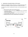
4.
Updating the embedded software of the modem
Updating the embedded software (firmware) of a Sigrand SG-17B modem,
as well as its managing, is carried out by means of a terminal program.
To initialize the process of updating the firmware, the following steps should
be taken:
• Disconnect the modem from the power source.
• Connect the modem’s control port «CONSOLE» (Fig. 7) to the USB
port of the computer.
• Start the terminal program chosen in accordance with Section 1.3 of
this manual at the computer.
• Press the button “IAP” on the front panel of the modem (Fig. 7).
• Keeping the button pressed, feed the power to the modem.
Figure 7
30
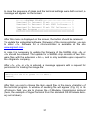
In case the sequence of steps and the terminal settings were both correct, a
message will appear on the screen:
********ROGRAM UPDATE*************************
Download To Internal Flash ---------------- 1
Download To External Flash SDFE Infineon--- 2
Download To External Flash IDC Infineon---- 3
Jump New Program -------------------------- 4
*******************************************************
After this menu is displayed on the screen, the button should be released.
To update the embedded software (firmware) of the microcontroller, you are
to enter «1». Software for a microcontroller is available at the site
www.sigrand.com .
In case it is necessary to update the firmware of the SHDSL chip, «2» or
«3» should be entered. The update for a SHDSL chip consists of two firmware files with the extension «.bin », and is only available upon request to
the «Sigrand» company.
After «1», «2», or «3» is entered, a message appears with a request for
permission for loading the image-file:
Waiting for the file (press 'a' to abort )
CCCCCCC_
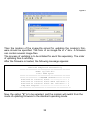
After that, you are to choose the item «send file» in the menu «transfer» of
the terminal program. A window of sending file will appear (Fig. 8); in its
«Protocol» field, you are to choose the «Y-Modem» transmission protocol
(here, the example of HyperTerminal from the standard OS Windows delivery set is taken).
31
Figure 8
Then the location of the image-file aimed for updating the modem’s firmware should be specified. The form of an image-file is «*.bin». A firmware
can contain several image-files.
The process of updating is to be initiated for each file separately. The order
of updating files is arbitrary.
After the firmware is loaded, the following message appears:
Download Completed Successfully
**********************************************
Name: sg17e01.bin
Size: 8468 Bytes
**********************************************
***************** PROGRAM UPDATE**************
Download To Internal Flash --------------- 1
Download To Internal Flash SDFE Infineon-- 2
Download To Internal Flash IDC Infineon--- 3
Jump New Program ------------------------- 4
***********************************************
Now, the option “4” is to be selected, and the modem will switch from the
mode of updating firmware to the standard operating mode.
32
Guaranty and warranties
The manufacturer guarantees the operability of the modem provided that
the user observes the operating instructions.
The warranty period is not less than 5 years starting with the day of
purchase as specified in the certificate, or, in case no mark of purchase is
made, starting with the day of issue as specified in the identification mark.
Warranty limitations :
Warranty will become null for modems operated at «aerial» or combined
(«underground+aerial») lines.
Manufacturer’s address:
Av. Lavrentyeva, 6/6,
Novosibirsk, Russian Federation,
«Sigrand» LLC
Тel.: (8-383) 332-94-37
Fax: (8-383) 332-02-43
www.sigrand.com
33
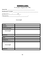
WARRANTY CARD
for modem «Sigrand SG-17B»
Serial № _________________________________________
Modification modem _____________________________________
produced in «____»_______20___.
Checked by _______________/_____________/
locus sigilli
Vendor
Address
Telephone
Date of purchase
locus sigilli
Signature
Buyer
Address
Telephone
Date of purchase
locus sigilli
Signature
34
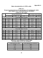
Appendix А
Main characteristics of «TPP» cable
Table А.1.
Frequency dependences for parameters of a twisted-pair cable
with copper cores and polyethylene insulation
(cables of «TP» type)
Secondary parameters
Primary parameters
f,
KHz R~, Ohm/km L, H/km *10-4 G, S/km *10-4
|Z|, Ohm α, dB/km
Core diameter: 0.4 mm
20
278
5.51
1.13
225.2
6.81
50
280
5.51
4.24
152.6
9.12
100
283
5.50
11.3
125.7
10.3
250
316
5.46
42.2
113.7
12.2
500
394
5.35
120
110.5
15.6
700
455
5.26
188
109.1
18.2
1000
535
5.15
305
107.7
21.7
Core diameter: 0.5 mm
20
181
5.50
1.13
185.1
5.15
50
182
5.50
4.24
133.3
6.48
100
189
5.49
11.3
118.0
7.17
250
234
5.40
42.2
111.6
9.21
500
310
5.23
120
108.8
12.4
700
361
5.26
188
107.4
14.6
1000
424
5.04
305
106.3
17.2
Table А.2. Loop resistance of the cable
as depending on the core diameter:
Core diameter (mm)
0.32
0.4
0.5
0.64
Loop resistance (Ohm/km)
432
278
180
110
35
36