1
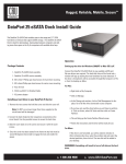
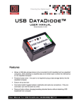
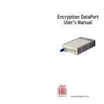
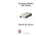
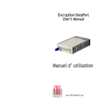
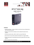
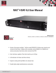
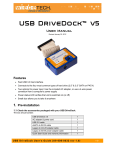
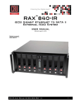
DataPort® 10 Secure User Manual
Models Covered:
DataPort 10 Secure with AES 128
DataPort 10 Secure with AES 256
• Hardware-based AES 128-bit or 256-bit Encryption - Offers affordable military-grade AES 128bit or 256-bit data protection that encrypts the entire hard drive - including boot sector, OS,
temp, and swap
• Meets Industry Standards - All CRU Secure 256-bit product architecture and encryption
engine designs meet FIPS140-2, level 3 per
number 1471, and all CRU AES 256bit security chips are NIST & CSE validated (FIPS PUB 197).
• No Key Management - The encryption key is mounted to the back of the frame. Simply
remove the carrier and the hard drive is encrypted.
• DataPort 10 Design - A rugged metal design that incorporates a patented temperature
controlled cooling system for ultimate data protection.
A6-010-0002 Revision: 3.3
1. Pre-Installation Steps
Table of Contents
1. Pre-Installation Steps
1
1.1 Box Contents
1
1.2 Identifying Parts of your DataPort 10 Secure
1
1.3 Warnings and Notices
2
2. Installation Steps
1.1 Box Contents
The following list contains the items that are included in the
complete
for this device. Depending on which
and accessories you purchased, the package may
include fewer items than what are listed here. Please contact CRUDataPort if any items are missing or damaged:
2
2.1 Receiving Frame Installation
2
2.2 Hard Drive Installation
2
2.3 Operating the DataPort 10 Secure
2
2.4 Safe Carrier Removal
2
DataPort 10 Frame
1
2.5 Other
3
DataPort 10 Carrier
1
Options
2.5.1 Fan Failure Alarm
Accessories
3
3. Usage with Mac and Windows Operating Systems
3
4. Encryption
4
5. Frequently Asked Questions
Quantity
5
M3 x 5 pan head frame mounting screws
4
4
Molex-to-SATA Adapter Cable
1
5
DataPort Keys
2
Security Keys
3
Lanyards for Security Keys
3
Security Key ID Tag
3
Security Key Labels
6
1.2 Identifying Parts of Your DataPort 10 Secure
Key Lock
Mini-USB Security
Key Port
Carrier Handle
Page 1
frame. If no SATA power connectors are available, attach the
included Molex-to-SATA adapter cable to a Molex power plug.
Then plug the SATA end of the adapter cable into the rear of the
receiving frame.
2.2 Hard Drive Installation
Security Key
Error LED
Encryption
Enabled LED
Activity LED
Power LED
1.3 Warnings and Notices
Please read the following before beginning installation.
•
•
•
•
•
The main circuit board of the HDD carrier is susceptible to
static electricity. Proper grounding is strongly recommended to
prevent electrical damage to the enclosure or other connected
devices, including the computer host. Avoid all dramatic
movement, vibration and percussion.
Avoid placing the HDD carrier close to magnetic devices, high
voltage devices, or near a heat source, including any place
where the product will be subject to direct sunlight. Do NOT
allow water to make contact with any Security Keys, carrier or
receiving frame.
Though the Security Key port is mechanically identical to the
standard Mini-USB port, inserting Security Keys into any other
Mini-USB port will damage the keys and render them useless.
Please only use Security Keys in DataPort Secure products.
Likewise, inserting a Mini-USB cable or other device into the
DataPort 10 Secure Security Key port on the carrier can cause
internal damage and potentially lead to loss of data.
Any time power is cycled on the DataPort 10 Secure, the
encryption key will need to be installed in order to access the
data on the drive.
2. Installation Steps
2.1 Receiving Frame Installation
a. Slide the receiving frame into an open 5.25” bay.
b. Secure the receiving frame to the chassis with the four screws
provided.
c. Attach the SATA data cable to the rear of the receiving frame
and the other end to the corresponding SATA port on the computer’s motherboard.
d. Attach the SATA power connectors to the rear of the receiving
a. If the carrier is bundled with a frame, use the included set of DataPort Keys to unlock the carrier and then remove it from the frame.
b. Use a Phillips-head screwdriver to remove the screw securing the
carrier cover to the back of the carrier, then slide the cover off.
c. Insert a SATA hard drive into the
nector inside the carrier.
power and data con-
d. Secure the hard drive to the carrier by using the mounting
screws provided.
e. Attach the Temperature Control Cooling Sensor to the top of the
hard drive with a piece of tape.
f. Replace the cover and secure it with the screw you removed in
Step B. into the rear of the carrier.
g. Reinsert the carrier into the frame.
2.3 Operating your DataPort 10 Secure
a. If you have not already done so, slide the DataPort 10 Secure
carrier into an open DataPort 10 frame (may be sold separately)
on your computer.
b. Insert the Security Key into the Mini-USB Security Key Port on
the face of the receiving frame.
c. Insert a DataPort Key into the key lock and turn it 90 degrees
clockwise to power on the unit.
d. When both green LEDs are lit, showing that the drive is ready
and encryption is activated, remove the Security Key and store
it in a safe location.
When any hard drive is
used with the DataPort 10 Secure it
will show up as a blank, unallocated drive and you’ll need to format
the drive inside the enclosure before you can use it. Note that
formatting a drive will erase all data on the drive, so be sure
to back up your data before beginning this operation. See
Section 3 for instructions on how to format the drive with Mac or
Windows operating systems.
2.4 Safe Carrier Removal
a. Turn off the computer or properly dismount the drive from
Page 2
the system. See Section 3 for instructions on how to properly
dismount the drive from Mac or Windows systems.
b. Use the DataPort Key to turn the keylock 90 degrees counterclockwise to unlock and power off the unit.
c. Pull the carrier by the handle towards you to remove the carrier.
2.5 Optional Configuration Settings
2.5.1 Fan Failure Alarm
3.1.3 Mounting and Unmounting Volumes
The fan failure alarm function is a standard feature on the DataPort
10. If the cooling fan should fail, an alarm will beep and the green
LED on the upper left corner of the DataPort will flash indicating
fan failure. Remove the jumper on JP6 on the frame (see picture) to
silence the audible alarm. The jumper is located directly below the
fan power connector on the DataPort 10 Secure circuit board.
If the hard drive installed in the DataPort 10 Secure was previously
formatted with the correct Security Key inserted into the Mini-USB Security Key Port on the face of the receiving frame, then you can begin
using the volume right away. If the drive is unformatted, a message
will appear on the desktop saying that the disk is unreadable. You can
use OS X’s Disk Utility to easily format the drive (see section above).
Jumper
3. Usage with Mac and Windows Operating Systems
3.1 Usage with Mac OS X
3.1.1 Compatibility
The DataPort 10 Secure supports 2.5” and 3.5” SATA hard drives.
3.1.2 Formatting a Drive
To format, use Mac OS X’s Disk Utility (found in the applications
folder). The DataPort 10 Secure must have been powered on with
the Security Key present and both the Power and Encryption Ready
LEDs must be lit. See Section 2.3 for instructions on how to do so.
a. Click on the drive in the window to the left (see picture to right).
b. Click the Erase tab in the window to the right (see picture to
right).
c. Select the format type. Most users prefer Mac OS Extended
with Journaling (HFS+), which is required for compatibility with
Time Machine (OS 10.5 or newer). If you need to use your DataPort 10 Secure with both Mac and Windows computers, select
MS-DOS File System instead.
d. Enter a name for the new volume and then click “Erase” to start
the process.
Unmount the volume before powering
down the unit by dragging the volume’s
icon to the trash bin, or by selecting
the volume then pressing Command-E.
Disconnecting the unit without first unmounting the volume can result in data
loss (see picture to the right).
3.1.4 Creating a Boot Drive
To activate this feature, you must first install OS X on the hard drive
in your carrier. The easiest way to do this is to clone an existing system drive using a utility such as Carbon Copy Cloner or Super Duper.
Next, go to System Preferences --> Startup Disk. A window will list
the available bootable volumes. Select the volume from which you
wish to boot. Another method is to hold down the Option key during boot up. A screen should appear that allows you to select the
volume you wish to use. This is useful if you wish to boot from your
DataPort 10 Secure hard drive only some of the time.
3.2 Usage with Windows Operating Systems
3.2.1 Compatibility
The DataPort 10 Secure supports 2.5” and 3.5” SATA hard drives.
3.2.2 Formatting a Drive
To format, use the Disk Management utility. The DataPort 10
Secure must have been powered on with the Security Key present
and both the Power and Encryption Ready LEDs must be lit. See
Section 2.3 for instructions on how to do so.
a. Right-click on My Computer, then select Manage. The Computer Management window will open.
Page 3
b. In the left pane of this window, left-click on Disk Management.
c. The drive should appear in the list of Disks in the lower middle/
right pane (see picture below). You may need to scroll down to
see it. If the drive is already formatted, you can identify it easily
by its volume name. If it’s unformatted, the Drive Properties Box
will say “Unallocated” and you’ll need to initialize the disk before formatting it. Initialize the disk by right-clicking the Device
Properties Box and selecting Initialize Disk.
DataPort 10 Secure is properly connected and turned on, a window
may open to allow you access to the volume. If no window appears,
you can find the volume by double-clicking the “My Computer” icon.
Unmount the DataPort 10 Secure before powering it down by singleclicking the green arrow icon on the task bar (in Windows XP) or the
USB plug icon with the green checkmark on the taskbar (Windows Vista
and Windows 7), then selecting “Safely
remove….” Windows will indicate
when it is safe to disconnect the
DataPort 10 Secure. Disconnecting
the unit without first ejecting it
can result in data loss.
4. Encryption
• T he DataPort 10 Secure uses full disk hardware encryption to
encrypt the entire contents of the drive - including the boot
sector, operating system and all files - without performance
degradation.
d. To format the drive, right-click the Drive Properties Box and
select Format.
e. If you are prompted to select a partition type, select MBR for
NOTE: Windows XP does not support GPT or volumes larger
than 2TB.
volumes 2TB or smaller, or GPT for volumes larger than 2TB.
f. Click through several more windows, leaving the default settings, until you see a window that allows selection of a file
system. Choose NTFS and enter a name for the new volume.
Be sure to check the box labeled “Perform a quick format”
unless you want to completely erase any data on the drive
and have time to wait. A quick format should take less than a
minute, while standard formatting may take several hours.
g. Click “Next” and then “Finish” to start the format process.
When the format is complete, the Drive Properties Box will
update to show the new volume name. The new volume can
now be found in My Computer.
3.2.3 Mounting and Unmounting Volumes
If the hard drive installed in the DataPort 10 Secure was previously
formatted with the correct Security Key inserted into the Mini-USB
Security Key Port on the face of the receiving frame, then when the
• The encryption key must be installed prior to powering on the
DataPort 10 Secure for the data to be decrypted on the drive. If
the key is externally connected to the Mini-USB Security Key Port
and is not internally installed, then once it has been accepted,
it may be removed and stored apart from the data so that in the
event that the drive is lost or stolen, the data is protected.
• When a drive is formatted using an encryption key, the same
or a duplicate key must be used in order to access the data.
There is no “back door” to access the data; lost keys make data
recovery virtually impossible.
5. Frequently Asked Questions (FAQ)
Q: What
do the
LED lights
indicate?
# LED
Name
Color
State
A: 1 Drive Activity
Amber
2 Power
Green
3 Key Error
4 Encryption
Flashes when
Intermittent the drive is being
accessed.
Solid
Unit is powered on.
Flashing
Fan Failure.
Solid
Encryption engine
error. Contact
Technical Support.
Flashing
The Security Key is
not present or is not
functioning.
Solid
The Security Key
is present and
encryption is enabled.
Red
Green
Description
Page 4
Q: Why can’t I access my data when I turn on my unit?
A: If you have data on the drive, don’t panic! Barring the failure of the
hard drive your data is still intact, but is not reachable because the
drive was not formatted within this unit using the correct Security
Key. If you previously formatted the drive using a Security Key,
power off the unit and insert the correct Security Key into the MiniUSB Security Key port on the front of the carrier. Then turn your unit
back on. When both green LEDs are lit, showing that the drive is
ready and encrypted, you should then be able to access your data.
You can then remove the Security Key and store it in a safe location.
Q: C
an I use my 128-bit encrypted hard drive in a 256-bit
enclosure, or a 256-bit encrypted hard drive in a 128-bit
enclosure?
A: No. 128-bit and 256-bit encryption are not cross-compatible.
Contacting Technical Support
Still need help? Please contact our Technical Support team through
CRU-DataPort.com. Or call us toll free at (800) 260-9800, or directly
at (360) 816-1772.
If you did not format the drive using a Security Key, you will need
to make a backup copy of your data and format the drive using
the correct Security Key. See Section 3 for instructions on how to
format the drive with Mac or Windows operating systems.
Q: I turned my unit off and back on and now I cannot access
my data. Why?
A: Cycling power on the unit will require you to reinsert the Security
Key into the Mini-USB Security Key port before turning the unit
back on, even if you have not turned your computer off. If the unit
is on, power it off and insert the correct Security Key into the
Mini-USB Security Key port on the front of the carrier. Then turn
your unit back on. When both green LEDs are lit, showing that
the drive is ready and encrypted, you should then be able to access your data. You can then remove the Security Key and store it
in a safe location.
Q: W
hy can’t I use another device through the Mini-USB port
on the front of the DataPort 10 Secure carrier?
A: T his port is used by the Security Key to provide the encryption
key to the unit hardware that will allow the unit to access the
data on your hard drive. It does not pass data to the drive itself.
Under no circumstances should you insert anything other
than a Security Key into the Mini-USB Security Key Port.
Though it is mechanically identical to the standard Mini-USB
port, inserting a Mini-USB cable or other device into the MiniUSB Security Key Port on the carrier can cause internal damage
and potentially lead to loss of data.
Likewise, inserting the Security Keys into any other Mini-USB
port will damage the keys and render them useless. Please only
use the Security Keys in DataPort Secure products.
If you have already tried to use another device through this port
or have inserted the Security Key into another device’s Mini-USB
port, first check to see if your Security Key still works in your
DataPort 10. If it does not, please contact Technical Support.
Page 5
Contacting Technical Support
Still need help? Please contact our Technical Support team through
CRU-DataPort.com. Or call us toll free at (800) 260-9800, or directly
at (360) 816-1772.
6. Technical Specifications
Product Warranty
Product Name
DataPort 10 Secure with Internal Key
Interface Types &
Speeds
SATA: up to 150 Mbps
Compatibility
• 2.5” SATA Hard Drives
• 3.5” SATA Hard Drives
Data Connectors
One (1) eSATA connector
Encryption
128-bit AES (Advanced Encryption Standard) or 256-bit AES 128-bit and 256-bit encryption are not cross-compatible
Connector
Insertion Rating
25,000+ Carrier-to-Frame
Operating System
Requirements
• Windows 7, Vista, or XP
• Mac OS X
• Linux distributions that support SATA, USB, or FireWire 800
Compliance
EMI Standard: FCC Part 15 Class B, CE
EMC Standard: EN55022, EN55024
FIPS: FIPS 140-2, FIPS PUB 197
Shipping Weights
3.00 pounds (includes accessories)
Dimensions
5.75” x 7.87” x 1.61” (146mm x 200mm x 41mm)
Warranty
3-year limited warranty. See warranty statement for details and
limitations.
We don’t want anything to go wrong with your CRU-DataPort
product. But if it does, Tech Support is standing by and ready
to help. Contact us at http://www.cru-dataport.com/technicalsupport/customer-technical-support.php
CRU-DataPort (CRU) warrants this product to be free of significant defects in material and workmanship for a period of
three years from the original date of purchase. CRU’s warranty is nontransferable and is limited to the original purchaser.
Limitation of Liability
The warranties set forth in this agreement replace all other warranties. CRU expressly disclaims all other warranties,
including but not limited to, the implied warranties of merchantability and fitness for a particular purpose and noninfringement of third-party rights with respect to the documentation and hardware. No CRU dealer, agent, or employee
is authorized to make any modification, extension, or addition to this warranty. In no event will CRU or its suppliers be
liable for any costs of procurement of substitute products or services, lost profits, loss of information or data, computer
malfunction, or any other special, indirect, consequential, or incidental damages arising in any way out of the sale of,
use of, or inability to use any CRU product or service, even if CRU has been advised of the possibility of such damages.
In no case shall CRU’s liability exceed the actual money paid for the products at issue. CRU reserves the right to make
modifications and additions to this product without notice or taking on additional liability.
FCC Compliance Statement: “This device complies with Part 15 of the FCC rules. Operation is subject to the following
two conditions: (1) This device may not cause harmful interference, and (2) this device must accept any interference
received, including interference that may cause undesired operation.”
This equipment has been tested and found to comply with the limits for a Class B digital device, pursuant to Part 15
of the FCC Rules. These limits are designed to provide reasonable protection against harmful interference when the
equipment is operated in a home or commercial environment. This equipment generates, uses, and can radiate radio
frequency energy and, if not installed and used in accordance with the instruction manual, may cause harmful interference to radio communications.
In the event that you experience Radio Frequency Interference, you should take the following steps to resolve the
problem:
1) Ensure that the case of your attached drive is grounded.
2) Use a data cable with RFI reducing ferrites on each end.
3) Use a power supply with an RFI reducing ferrite approximately 5 inches from the DC plug.
FOR HOME OR OFFICE USE
4) Reorient or relocate the receiving antenna.