1
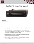
DataPort 25
Manual
www.CRU-DataPort.com
DataPort
“
About CRU-DataPort
Founded in 1986 and based in Vancouver, Washington, CRU-DataPort
develops and markets computer data security and storage devices. The
company’s DataPort™ brand of removable storage modules, with over
2,000,000 units installed in computers worldwide, has become the de
facto standard for Data Security, and the recognized name when it
comes to removable storage modules for government, education and
corporate IT departments. DataPorts are rated for 25,000 insertions
and include fans to protect your disk drive.
CRU-DataPort products are available through major distributors, OEMs,
VARs, and a host of resellers and systems integrators throughout the
world. For more information about CRU-DataPort, visit our website at
www.CRU-DataPort.com.
Table of Contents
About CRU-DataPort................................................................................. ii
General Description..................................................................................1
Package Contents ....................................................................................1
General Configuration/Operation Information ............................................1
IDE operation......................................................................................1
Serial ATA operation ............................................................................2
Carrier removal ...................................................................................2
Preparation for Installation .......................................................................3
Frame Installation ....................................................................................4
Hard Drive Activity LED ............................................................................5
Mounting a Hard Drive in the Carrier .........................................................5
Technical Support ....................................................................................5
Limited Product Warranty .........................................................................6
Product Remedies ....................................................................................6
Limitation of Liability ................................................................................6
Page ii
www.CRU-DataPort.com
www.CRU-DataPort.com
Page iii
General Description
The DataPort™ 25 is a portable storage device for your computer hard
drive that can be easily removed from the computer. The DataPort 25
consists of a frame and carrier with dual 2.5" drive support mounting
chassis and metal front bezel clamshell cover. The frame can be fitted
into any standard 3.5" floppy drive bay.
Package Contents
The DP25 includes all of the hardware necessary to install a 2.5" hard
drive in a 3.5" floppy drive bay. Before installing, verify that the
following items have been included in the package (the contents may
come packaged inside the carrier):
Quantity
1
Description
DataPort 25 frame assembly
1
DataPort 25 carrier assembly
8
M3 x 4mm" Phillips pan-head screws for hard
drive mounting
4
M3 x 5mm Phillips pan-head screws for frame
mounting with rails
4
M3 x 4mm Phillips pan-head screws for frame
mounting in case
2
M3 x 4mm Phillips pan-head screws for carrier
cover mounting
2
Keys for lock
General Configuration/Operation Information
The DataPort™ 25 IDE carrier can be configured with either one or two
IDE or Serial ATA 2.5" drives that can be easily removed from the
computer. The universal frame will accept either an IDE or a Serial ATA
carrier and with the proper cabling can provide access to those drives
by the OS.
Note:
There is a configuration management feature that will cause
the green power on LED to flash off and on if the installed
carrier does not have correct cabling from the frame to the
system when the DataPort 25 is powered on.
IDE operation
For IDE operation, the frame board 40-pin connector (JP2) must be
cabled with an ATA66 80-conductor ribbon cable to either an IDE host
bus adapter or the primary or secondary IDE channel on the
Motherboard. Since there can be two IDE drives installed in the carrier,
DO NOT install any other devices on the same channel as the
Page iv
www.CRU-DataPort.com
www.CRU-DataPort.com
Page 1
DataPort 25. When multiple IDE drives are used, they have to be
jumpered such that there is one drive as a master and one drive as a
slave. Since both drives are off the same cable connector, jumpering as
cable select is NOT supported.
Serial ATA operation
For Serial ATA operation, the lower drive in the carrier is connected to
the left-most Serial ATA data connector on the rear of the frame (JP4).
The upper drive is connected to the right-most data connector (JP5).
These cables can be up to 1000 mm in length. There is also a 2-pin
header on the frame of which pin 1 can be connected to the host
activity open collector LED driver.
Figure 2 – Ejection lever
Preparation for Installation
Figure 1 – Back
To support both carrier types, connect all three data cables to the
DataPort 25 frame board.
WARNING!
Unlock the DataPort 25 before attempting to remove the
carrier.
1.
To prevent data loss, read this manual thoroughly before installing
or operating the DataPort.
2.
Before touching any electrical equipment, ground yourself by
touching the metal part of your computer chassis to discharge
static electricity and help prevent any damage to your computer.
CRU-DataPort is not responsible for static discharge
damage.
3.
Gather the following tools and needed items:
•
Philips screwdriver
•
Small flat-head screwdriver
•
Computer Users Manual
•
Internal IDE or Serial ATA data cable(s)
•
Available Serial ATA port(s) (Serial ATA version)
Carrier removal
To remove the carrier, first make sure the ejection lever is fully
extended. Then gently press it in to eject the carrier.
Page 2
www.CRU-DataPort.com
www.CRU-DataPort.com
Page 3
Frame Installation
WARNING!
8.
Locate the data cable and connect it to the connector on the rear
of the frame.
9.
Connect the DC power cable to the frame by locating an available
4-pin DC floppy style power cable from the computer power supply
and then plugging it into the power plug (JP3) on the frame.
Only use screws provided by CRU to install your DataPort 25 frame.
Use of standard M3 screws will prevent proper functionality of your
DataPort 25.
1.
Turn off the computer and disconnect its power cord from the
electrical outlet.
2.
Wait one minute for any residual energy to dissipate from your
computer.
3.
Remove the cover of the computer.
4.
Locate an empty externally accessible 3.5" bay in which you will
mount the DataPort frame assembly, and then remove any filler
plates that may be present.
5.
If the drive bay requires mounting rails, install one on each side of
the frame. The mounting rails should be provided with your
computer system.
6.
Mount the frame assembly by sliding the frame into the 3.5" bay
from the front of the PC case.
7.
Using the screws provided, secure the frame assembly to the
computer case using the frame’s side mounting holes (see Figure
3). Your DataPort frame also has bottom mount holes in case you
need to bottom mount the unit.
Side mounting holes
Figure 4 – Location of JP3 Power Plug
The frame installation is now complete.
Hard Drive Activity LED
The front of the DataPort 25 has two LEDs: a green LED that lights up
when the power to the hard drive is on, and an amber LED that lights
up when activity is taking place on the hard drive.
Mounting a Hard Drive in the Carrier
1.
Remove the two screws from the back of the carrier. Slide the
metal cover off.
2.
Install the first drive in the carrier. Connect the drive to the
connector in the carrier and use the four screws provided to mount
the drive.
3.
If there is a second hard drive, install it now.
4.
After the drive has been installed, slide the cover over the drive
mounting chassis and insert the screws in the rear of the cover to
secure it.
5.
Insert the carrier into the frame assembly. Ensure that the lock is
in the OPEN (vertical) position.
6.
Once the carrier has been seated in the frame the keylock must be
turned clockwise 90 degrees (horizontal) to engage the mechanical
lock and enable power to the devices in the carrier.
You have finished the installation and your DataPort 25 is ready to
operate.
Bottom mounting holes
Technical Support
Figure 3 – Location of mounting holes
Page 4
www.CRU-DataPort.com
Please visit our website for the latest information and technical support
options: http://www.CRU-DataPort.com.
www.CRU-DataPort.com
Page 5
Limited Product Warranty
CRU-DataPort warrants the DataPort 25 to be free of significant defects
in material and workmanship for a period of three (3) years from the
original date of purchase. CRU-DataPort’s warranty is nontransferable
and is limited to the original purchaser.
Product Remedies
CRU-DataPort’s entire liability and the original purchaser’s exclusive
remedy for any breach of warranty shall be, at CRU-DataPort’s option,
either (a) return of the price paid, or (b) repair or replacement of the
hardware, provided that the hardware is returned to CRU-DataPort with
a copy of the sales receipt or applicable documentation. Any
replacement hardware will be warranted for the remainder of the
original warranty period.
These remedies are void if the hardware fails because of accident,
abuse, misapplication, or modification (this will be determined by CRUDataPort).
Limitation of Liability
The warranties set forth in this agreement replace all other warranties.
CRU-DataPort expressly disclaims all other warranties, including but not
limited to, the implied warranties of merchantability and fitness for a
particular purpose and non infringement of third-party rights with
respect to the documentation and hardware. No CRU-DataPort dealer,
agent or employee is authorized to make any modification, extension,
or addition to this warranty. In no event will CRU-DataPort or its
suppliers be liable for any costs of procurement of substitute products
or services, lost profits, loss of information or data, computer
malfunction, or any other special, indirect, consequential, or incidental
damages arising in any way out of the sale of, use of, or inability to use
any CRU-DataPort product or service, even if CRU-DataPort has been
advised of the possibility of such damages. In no case shall
CRU-DataPort’s liability exceed the actual money paid for the products
at issue.
CRU-DataPort reserves the right to make modifications and additions to
this product without notice or taking on additional liability.
Revision 1.0
Page 6
www.CRU-DataPort.com