1
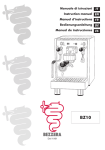
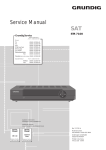
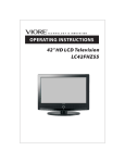
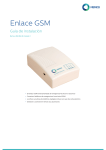
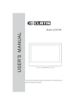
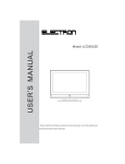
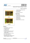
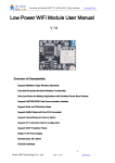
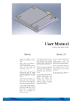
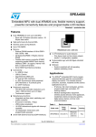
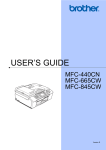
AW-NH580
IEEE 802.11 b/g/n Wireless LAN, Bluetooth
, GPS and FM Combo Module
Datasheet
Version 0.2
-1-
Document
release
Date
Version 0.1
2010/09/06
Modification
Initial Version
Initials
Approved
Kai
Wu
CE
Huang
Kai
Wu
CE
Huang
1. Corrected Model Name in 1-3.
Specifications Table
Version 0.2
2010/11/11
2. Corrected General description in 1-2.
Key Features
3. Add shipping information
-2-
Table of Contents
1. General Description
1-1. Product Overview and Functional Description
1-2. Key Features
1-3. Specifications Table
2. Electrical Characteristic
2-1. Absolute Maximum Ratings
2-2. Recommended Operating Conditions
2-3. DC Characteristics for Host I/O
2-4. GPS/BT/FM Host Interface
2-5. Multimedia features
2-6. WLAN interface
2-7. Reset and Regulator control signaling
2-8. LPO Clock (RTC_CLK)
2-9. Reset and Regulator Control Signaling
3. Pin Definition
3-1. Pin Description
3-2. Pin Location (TOP View X-Y Coordinate)
4. Mechanical Information
-3-
1. General Description
1-1. Product Overview and Functional Description
AzureWave Technologies, Inc. introduces the first IEEE 802.11b/g/n WLAN, BT+BLE, GPS and FM
TX/RX combo module - AW-NH580. The module is targeted to mobile devices including, Digital Still
Cameras (DSCs), Portable Media Players (PMPs), Portable Navigation Devices (PNDs), Personal
Digital Assistants (PDAs), Tracking Devices, Gaming Devices, and mobile phones which need small
footprint package, low power consumption, multiple OS support. By using AW-NH580, the customers
can easily enable the Wi-Fi, BT, GPS and FM embedded applications with the benefits of high design
flexibility, short development cycle, and quick time-to-market.
Compliance with the IEEE 802.11b/g/n standard, the AW-NH580 uses DSSS, OFDM, DBPSK, DQPSK,
CCK and QAM baseband modulation technologies. A high level of integration and full implementation
of the power management functions specified in the IEEE 802.11 standard minimize the system power
requirements by using AW-NH580. In addition to the support of WPA/WPA2 (personal) and WEP
encryption, the AW-NH580 also supports the IEEE 802.11i security standard through AES and TKIP
acceleration hardware for faster data encryption. The AW-NH580 is also Cisco Compatible Extension
(CCX) certified. For the video, voice and multimedia applications the AW-NH580 support 802.11e
Quality of Service (QoS).
For Bluetooth operation, the AW-NH580 is Bluetooth V1.2, V2.0/V2.1+Enhanced Data Rate (EDR),
V3.0 and V4.0 (including Bluetooth Low Energy) compliant. The AW-NH580 supports extended
Synchronous Connections (eSCO), for enhanced voice quality by allowing for retransmission of
dropped packets, and Adaptive Frequency Hopping (AFH) for reducing radio frequency interference.
It provides easier to connect devices, lower power consumption and improved security.
For FM receiver/transmitter, the AW-NH580 is 70-MHz to 108-MHz FM bands supported and supports
the European Radio Data Systems (RDS) and the North American Radio Broadcast Data System
(RBDS) modulations.
For GPS, The AW-NH580 supports Assisted, Autonomous, and Enhanced Autonomous operating
mode and all industry aiding standards for AGPS applications, including GSM/CDMA/WCDMA, 3GPP
and TIA.
Typical application about GPS/FM/BT, The (a)GPS subsystem provides the accurate positioning
information. In a Mobile Phone application, the BT link is the medium for PCs, telephones, PDAs and
other peripherals to communicate together on an ad-hoc basis. The FM subsystem is useful to listen to
radio stations or may be used to send music through e.g. a car radio system.
-4-
The audio and voice path is using either the SLIMbus, the PCM or I2S interfaces to carry BT SCO and
eSCO, as well as FM stereo Rx and TX data and BT stereo data for A2DP. Next to this, the FM stereo
RX can use the analog audio output interface.
A system clock request signal is provided to manage the system clock coming from TCXO. The system
clock request signal may be shared with multiple sources. The low power clock is used to manage the
AW-NH580 low power modes.
The AW-NH580 supports standard interface SDIO v1.10 (4-bit and 1-bit) for WLAN, High-speed UART
interface for BT/FM/GPS host controller interface and PCM/I2S for BT/FM audio data. The demodulated
FM audio signal is available as line-level analog stereo output. AW-NH580 is suitable for multiple mobile
processors for different applications. With the combo functions and the good performance, the AWNH580 is the best solution for the consumer electronics and the laptops.
-5-
1-2. Key Features
General
Integrates ST-Ericsson solutions of ST-Ericsson CG2900 GPS/BT/FM SoC and
CW1100 Wi-Fi SoC
Depopulated 100-pin WLCSP 9.60 mm x 9.60 mm x 1.3 mm with 0.95 mm pitch
SDIO interfaces support for WLAN
High speed UART and PCM/I2S for Bluetooth, GPS and FM
Audio DSP: embedded BT wide band speech SBC codec, A2DP SBC stereo encoding
and L2CAP encapsulation to reduce host processing
Direct loop-through mode from FM Rx audio to BT A2DP
Flexible Power Supply(3.6V~4.8V)
Multiple power saving modes for low power consumption
Lead-free /Halogen Free Design
Power supply
–Integrated SMPS for direct battery connection
–Software adjustable output voltage to minimize power consumption
Clocks
–Low power clock input at 32.768 kHz required
WLAN
Single - band 2.4 GHz 802.11 b/g/n
Supports antenna diversity
Supports IEEE 802.11d, e, h, i, j, r, k, w
Security–WEP, WPA/WPA2 (personal), AES (HW), TKIP (HW), CKIP (SW).
WMM/WMM-PS/WMM-SA
The AW-NH580 supports also the CCX version 5.
Bluetooth
Full compliance with Bluetooth specification version 4.0 (including Bluetooth Low
Energy)
Fully supports Bluetooth Core Specification version 2.1/2.0 + EDR and 3.0 features
-6-
FM
True worldwide FM band support (70 -108 MHz
for US, Europe and Japan), for wire
antenna with single application
Embedded (loop) antenna support for FM TX/RX
FM TX on dual FM channel (with RDS AF list) for robust FM transmission
R(B)DS modulator/demodulator and encoder/decoder compliant with EN 62106
FM line-level analog stereo output available
GPS
Advanced proprietary multipath algorithms for robust low-dropout tracking in indoor
and outdoor urban canyons
GSM, WCDMA and CDMA control plane aGPS assistance data standards
Exceeds 3GPP and TIA performance requirements
SUPL user plane aGPS assistance data
14 search and three track channels used to track up to 47 individual satellite signals
Measurement engine with a search capacity of 35000 correlators
The principal function of the host software is to perform satellite navigation
calculations
-7-
Block Diagram
A simplified block diagram of the AW-NH580 module is depicted in the figure below.
AW-NH580
-8-
1-3. Specifications Table
*Specifications are subject to change without notice
Model Name
AW-NH580
Product Description
Wireless LAN &Bluetooth & FM
WLAN Standard
IEEE 802.11b/g/n, Wi-Fi compliant
Bluetooth Standard
Bluetooth 2.1+Enhanced Data Rate (EDR) / BT3.0+HS/BT4.0
SDIO/SPI for WLAN
Host Interface
UART for GPS, Bluetooth and FM
Digital PCM/I2S for FM/Bluetooth
Audio Interface
Analog line level i/o for FM.
I2S for FM/Bluetooth
Dimension
9.6 mm X 9.6 mm x 1. 3 mm
Package
LGA package
Operating Conditions
Voltage
Input supply for internal PMU: 3.8 ~ 4.8V
Input supply for host I/O : 1.8 to 3.6V
Temperature
Operating: -20 ~ 70oC ; Storage: -40 ~ 85oC
Relative Humidity
< 60 % ( storage) <85% (operation)
Electrical Specifications
2.4 GHz Band WLAN/Bluetooth
Frequency Range
1575.42 MHz GPS L1 radio band
70 MHz to 108 MHz FM bands
802.11b: USA, Canada and Taiwan – 11
Most European Countries – 13
Number of Channels
Japan – 14
802.11g: USA and Canada – 11
Most European Countries – 13
*DSSS, OFDM, DBPSK, DQPSK, CCK, 16-QAM, 64-QAM for WLAN
Modulation
*GFSK (1Mbps), Π/4 DQPSK (2Mbps) and 8DPSK (3Mbps) for
Bluetooth
-9-
WLAN:
TBD
GPS
TBD
Output Power
Bluetooth:
TBD
FM
TBD
WLAN:
TBD
GPS
TBD
Receive Sensitivity
Bluetooth:
TBD
FM:
TBD
WLAN
802.11b: 1, 2, 5.5, 11Mbps
Data Rates
802.11g: 6, 9, 12, 18, 24, 36, 48, 54Mbps
802.11n:MCS 0~7
Bluetooth
Bluetooth 2.1+EDR data rates of 1,2, and 3Mbps
Power Consumption
Not specified.
WPA™- and WPA2™- (Personal) support for powerful
encryption and authentication
AES and TKIP acceleration hardware for faster data encryption
and 802.11i compatibility
Security
Cisco® Compatible Extension- (CCX, CCX 2.0, CCX 3.0, CCX
4.0,CCX5.0) certified
SecureEasySetup™ for simple Wi-Fi® setup and WPA2/WPA
security configuration
Operating System Compatibility
Wi-Fi Protected Setup (WPS)
WEP
CKIP(Software)
TBD
- 10 -
2. Electrical Characteristics
2-1. Absolute Maximum Ratings
Symbol
Parameter
Min
Max
Units
VDD_CORE
Core Voltage for GPS/BT/FM (conditions@ at 1.8V)
-0.5
2.75
V
VDD_FM_PA
Core Voltage for FM Tx Power Amplifier
-0.5
2.75
V
VDDIO_G
I/O power supply for BT/FM/GPS
-0.5
2.75
V
VDDIO_W
I/O power supply for WLAN
-0.3
2.0
V
VBAT_DUT_G
Battery supply voltage
-0.5
TBD
V
VBAT_DUT_W
Battery supply voltage
-0.3
TBD
V
2-2. Recommended Operating Conditions (1)(2)(3)(4)(5)
Symbol
Parameter
Type
Min
Typ
VBAT_DUT_G/W
Regulator input supply voltage
Input
3.6(4)
-
4.8
V
1.8V_GBF
Digital supply voltage
Input
1.7
1.8
1.95
V
1.8V_WLAN
WLAN supply voltages 1.8 V
Input
1.65
1.8
1.95
V
Input
1.7
1.8
1.95
V
Input
1.65
1.8
1.95
V
GPS/BT/FM analog supply voltage and BT
VDD_CORE
Power Amplifier supply voltage
Max Units
VDDIO_G/W
I/O power supply for WLAN/BT/FM/GPS
VOUT
Regulator output supply voltage for GPS/BT/FM
Output
1.7
1.8
1.95
V
VDD_TCXO
TCXO supply voltage
Output
TBD
1.83
TBD
V
Input
3.6
-
4.8
V
Output
1.71
1.8
1.89
V
VBAT_PWR
1.8V_SMPS
Power stage supply that connected to
VBAT_DUT_G/W for SMPS
SMPS output (conditions@ at +/- 5% accuracy)
1. Supply ripple bellow 1.5 MHz shall be < 50 mVpp
2. Supply ripple from 1.5 MHz to 5 MHz shall be < 25 mVpp
3. Supply ripple above 5 MHz shall be < 5 mVpp
4. Below 2.75 V the FM TX output power is limited to 117 dBuV
2-3. DC Characteristics for Host I/O
Symbol
Parameter
Min
Typ.
Max
Units
0.35 * VDDIO
V
VIL
Low level input voltage
0
VIH
High level input voltage
0.65 * VDDIO
VOL
Low level output voltage (@ 100 µA)
0
0.2
V
VOH
High level output voltage (@ -100 µA)
VDDIO - 0.2
VDDIO
V
- 11 -
V
2-4. GPS/BT/FM Host Interface
The AW-NH580 is the optimal solution for any voice or data application that requires the Bluetooth SIG
standard Host Controller Interface (HCI) using a high-speed UART. The GPS subsystem, the FM
subsystem and the Bluetooth subsystem share the same high-speed UART.
2-4-1. UART Interface
The implemented UART interface is an asynchronous serial interface used for the
GPS/BT/FM control and data transfer.
Features
The following features are supported:
● 1-bit start generation
● 8-bits character size
● 1-bit stop generation
● No parity generation and detection
● Programmable standard baud rates from 38.4 kBaud to 1.8432 MBaud + additional baud rates
for fast data transfer from 2.5 MBaud up to 4.92 MBaud
● Automatic line error checking: stop bit failure (framing), RX overrun and break
● RTS/CTS hardware handshake
● RXD edge detect
Interface description
The UART interface consists of 4 wires:
● TXD_UART to transmit the data
The data is driven according to the local clock and features programmed.
● RXD_UART to receive the data
The data is read according to the local clock and features programmed.
● CTS_UART to indicate receiver is ready
This signal is active at low level and indicates the external modem it is ready to accept transmitted
data via RXD_UART.
● RTS_UART to indicate transmitter is ready
This signal is active at low level and asks to the external modem if it is ready to receive data via
TXD_UART.
- 12 -
Operations
The UART uses the modem signals Clear To Send (CTS) and Request To Send (RTS) for a hardware
handshake between the devices at both sides of the serial line. The notation for the signals is from the
Data Terminal Endpoint (DTE) point of view (i.e. the device at the other side of the serial line has to be
configured as Data Communication Equipment (DCE)). An example of a frame for a protocol with one
start bit (‘0’), 8 data bits (LSB first), no parity, and one stop bit (‘1’) is shown in Figure 2.4-1.
Figure 2.4-1. Example of a serial interface frame
Baud rates
The AW-NH580 supports a wide range from standard to high baud rates as listed in the following
chapters.
The default baud rate is provided from the static settings (115.2 kBaud). The AW-NH580 can start at
115.2 and 120 kBaud.
Supported baud rates
Table 2.4-1 lists the baud rates supported by the AW-NH580.
- 13 -
2-4-2. SLIMbus interface.
The SLIMbus interface is a synchronous serial interface used to transfer asynchronous HCI data, BT
ACL data, Isochronous BT (e)SCO voice data, BT A2DP stereo data in the case of host off loading with
transcoding in the AW-NH580, FM TX/RX audio data and GPS data.
A standard application may be running BT (Wideband) speech and/or FM Stereo
Transmission/Reception and GPS/BT/FM control or data, between the CG2900 and CW1100 in the AWNH580.
Features
The AW-NH580 implements the following SLIMbus features:
● Extended asynchronous protocol channels with double-ended flow control to handle half (full) duplex
BT HCI transport on one (two) SLIMbus simplex.
● Extended asynchronous protocol channel with double-ended flow control to handle half duplex GPS
transport on one SLIMbus simplex.
– Isochronous protocol channel, pushed protocol, or pulled protocol to handle simultaneously:
. Up to 2 BT (e)SCO 8 kHz and/or 16 kHz speech channels
. A 44.1 kHz or 48 kHz FM stereo output audio channel
. A 44.1 kHz or 48 kHz FM stereo input audio channel
● Several data format to support:
– 8-bit and 16-bit speech channel
– 16-bit audio channel
● LPCM offset sign-and-magnitude audio data coding on 16-bit data and coding support for PCM 2s
complement
● A large range of root frequency
● All gears and gear changes
● All sub-frame codings
● Assumes zero SLIMbus bit errors
● SLIMbus low power modes, bus pause and wake up
- 14 -
Interface description
The SLIMbus interface consists of 2 wires:
● SLIM_CLK to clock the data
It is active during all the SLIMbus transfer. The SLIMbus clock is driven by the external SLIMbus
Framer device.
● SLIM_DATA to transmit/receive data
The data is written on the positive edge and read on the negative edge of the clock.
The data uses a NRZI encoding and the data size handled depend on the protocol used.
In AW-NH580, the SLIMbus interface supports only the Interface Device class and the root frequencies
given in Table 2.4-2, which allows for 8, 16, 44.1 and 48 kHz sample rates usage. Depending on the root
frequency, the isochronous pushed or pulled protocol has to be used. Each of the isochronous ports use
four SLIMbus slots for the 16-bit data. The pushed or pulled protocol will be used when the root
frequency does not allow to create a segment rate equal to the sample rate.
Table 2.4-2. SLIMbus root frequencies
Root frequency
[MHz]
ConDescriptionn
16.384
SLIMbus natural frequency for 8, 16 kHz
16.9344
SLIMbus natural frequency for 44.1 kHz
18.432
SLIMbus natural frequency for 48 kHz
19.2
Cellular reference
19.8
Cellular reference
22.5792
24
24.576
26
SLIMbus natural frequency for 44.1 kHz
SLIMbus cardinal frequency for 8, 16, 48 kHz
Cellular reference
Each device connected to the SLIMbus is addressable by a unique 48-bit Enumeration Address (EA),
which incorporates manufacturer ID, product code, device index, and Instance value for a device as
described in Table 2.4-3.
- 15 -
Table 2.4-3. SLIMbus enumeration addresses
Operations
A port provides the connection path to data flow between Devices. The AW-NH580 supports 11 ports
(see Table 2.4-4) using asynchronous and extended asynchronous segments for HCI and GPS data
streaming, as well as isochronous segments (Pushed or pulled protocol) for speech (8-bits or 16-bits
data) and audio (16-bits data only) channels usage. Please, note the audio channel may use either two
16-bits ports for the left and right channels, or a single 32-bits port for both.
Table 2.4-4. SLIMbus configuration
Port number
CondDescriptionition
0
Speech channel 0 - Rx port
1
Speech channel 1 - Rx port
2
Audio receive channel (16-bits or 32-bits) - Rx port
3
Audio receive channel (16-its) - Rx port
4
Speech channel 0 - Tx port
5
Speech channel 1 - Tx port
6
Audio transmit channel (16-bits or 32-bits) - Tx port
7
Audio transmit channel (16-bits) - Tx port
8
Bi-directional port for asynchronous channel 0
- HCI Tx in full/half duplex
9
Bi-directional port for asynchronous channel 1
- HCI Rx in full duplex
10
Bi-directional port for asynchronous channel 2
- GPS Rx in half duplex
- GPS Tx in half duplex
- 16 -
The FM TX or BT A2DP burst mode is supported mapping the audio stereo channel to a SLIMbus
channel at a maximum segment rate of 500 kHz. The data flow can be controlled in two ways to average
the data throughput to the real sample rate:
1. Use the segment presence bit to indicate which segments in the 500 kHz stream carry data.
2. Pausing the bus
Please, note that in case 1 the bus may also be paused when there is no data to transfer.
Timing
The SLIMbus interface complies with the timing characteristics indicated in Figure 2.4-2.
Figure 2.4-2. SLIMbus interface timing (data transmit)
Table 2.4-5. SLIMbus interface timing characteristics (data transmit)
- 17 -
Table 2.4-5. SLIMbus interface timing characteristics (data transmit) (continued)
- 18 -
2-4-2. PCM/I2S interface
The implemented PCM/I2S interface is a synchronous serial interface used for the transfer of voice/audio
samples with full duplex capabilities. The PCM/I2S interface can also be used as audio interface when
the AW-NH580 is running the BT A2DP. A standard application may be running BT (Wideband) speech
and/or FM stereo transmission/reception, between the CG2900 and CW1100 in the AW-NH580
Interface description
The PCM interface consists of four wires:
●
FSC_IP is used to synchronize the slave device regarding data exchange.
FSC_IP signal is driven from the master and is an active pulse at high level. Its position is
configurable.
FSC_IP is used as word select in I2S mode.
●
DCLK_IP is used to clock the data
The activity duration depends on the way the PCM interface is used. The clock is driven from the
master.
●
DA_IP and DB_IP are used to transmit/receive respectively data A and B.
The PCM clock can be inverted, this allows the PCM interface to be used with I2S clocking.
Operations
The AW-NH580 supports both master and slave modes. In both modes, several configurations for the
PCM clock and frame frequencies are supported as given in Table 2.4-6. The PCM interface is able to
carry two streams with different sample frequencies multiplexed on a single PCM frame (e.g. a 32-bits
Left & Right at 48 kHz audio stream and an 8 kHz BT voice stream). This allows the simultaneous
transmission of both BT SCO and FM or both BT SCO and BT A2DP over the same PCM frame.
This is achieved according to the following principle:
● The FSC_IP frequency, whatever master or slave mode used, is the higher of the two streams
sample frequencies;
● A ratio_value features the frequency ratio of the two sampling frequencies. By convention, for the
stream having the smaller sampling frequency:
The output data is repeated over ratio_value PCM frames.
The input data is expected once every ratio_value PCM frames.
- 19 -
256
512
768
1024
1411.76
1536
2000
2048
2400(2)
2823.52
3072 (2)
4800(1)(2)
up to 2600(1)(3)(4)
Table 2.4-6. PCM frame duration in number of PCM clock cycles (master and slave modes)
32
64
96
128
-
192
250
256
300
-
384
-
-
16
32
48
64
-
96
125
128
150
-
192
-
-
-
8
16
24
32
-
48
-
64
75
-
96
-
-
44.1
-
-
-
-
-
32
-
-
-
-
64
-
-
-
48
-
-
-
16(6)
-
-
32
-
-
50
-
64
100
-
Up to 50
-
-
-
-
-
-
-
-
-
-
-
-
-
>=32
128
DCLK_IP
[kHz]
8
16
16
8
32
FSC_IP
[kHz]
(5)
(6)
1. Slave mode only
2. Clock frequency to support both FM audio (left & right channels) and BT-SCO (two channels) or both BT-A2DP and BT SCO.
3. PCM burst mode
4. Transmitting 16-bits left and 16-bits right as PCM data with FSC_IP =500 kHz requires minimum DCLK_IP=16 MHz
5. Only one 8-bits slot (A-law, µ-law voice channel) is allowed
6. Only one 16-bits slot (one PCM linear 16-bit voice channel) is allowed
In PCM framing mode a PCM frame starts with the PCM synchronization pulse. The position of this PCM
synchronization pulse is programmable as either the first (Figure 2.4-3) or the last (Figure 2.4-4) bit of
the frame. The number of PCM clock cycles between two PCM synchronization pulses defines the PCM
frame duration. There are up to 4 active slots supported within a PCM frame.
Each active PCM slot can be either 8 or 16 bits wide. For each slot, the slot start time relative to FCS_IP
can be programmed in PCM clock cycles. The timing of the PCM slots must be such that slot 0 is always
located before slot 1. It is however possible to only uses for example slot 1 and not slot 0. The DCLK_IP
activity can be programmed to be active until the last data bit, or can be continuously active over the
whole PCM frame. The PCM data in and data out can, per active slot, be programmed to be mapped on
DA_IP or DB_IP.
Figure 2.4-4 shows example of a PCM frame. The PCM frame starts with FSC_IP followed by the PCM
slots. In this example, the PCM frame consists of 4 PCM slots, the first one (slot 0) is 16 bits wide and
starts at PCM bit 1, the second one is 16 bits wide and start at PCM bit 17, and etc.
- 20 -
Figure 2.4-3. PCM transfer example (synchronization pulse is first bit of the frame)
Figure 2.4-4. PCM transfer example (synchronization pulse is last bit of the frame)
As it is important to synchronize the voice path, there are several configurations as outlined below:
● Bluetooth master and PCM master
In this case the voice path is synchronized.
● Bluetooth master and PCM slave
In this case, the voice path is synchronized.
● Bluetooth slave and PCM master
In this case the voice path is synchronized. The PCM timing is synchronized to the Bluetooth timing.
Due to the synchronization, PCM clock cycles within the PCM frame may be added or lost.
● Bluetooth slave and PCM slave
In this case, there is no voice path synchronization and, depending on the drift between the PCM
slave and the Bluetooth slave timings, a PCM sample is lost or duplicated.
- 21 -
Timing
In PCM framing mode the PCM synchronization pulse is a one PCM clock cycle pulse. The received
PCM data are sampled on the falling edge of the DCLK_IP, whilst the PCM data to send are output on
the rising edge of the DCLK_IP.
The PCM interface is defined according to the timing indicated in Figure 2.4-5. In slave mode, data is
sampled using the clock edges as shown in Figure 2.4-6.
In I2S mode, synchronization is performed using the FSC_IP as word select signal. The received I2S
data are sampled on the rising edge of the DCLK_IP, whilst the PCM data to send are output on the
falling edge of the DCLK_IP.
Figure 2.4-5. PCM interface timing (master mode)
- 22 -
Table 2.4-6. PCM master timings
1. T24MHz is one 24 MHz period: 41.66 ns
2. max DCLK_IP high/low time and FSC_IP high time corresponds to DCLK_IP at 128 kHz
3. min DCLK_IP high/low time and FSC_IP high time corresponds to DCLK_IP at 3072 kHz.
2.4-3 Second I2S interface
This second I2S interface is a synchronous serial interface used for the transfer of voice/audio samples
with full duplex capabilities (BT) or half duplex (FM).
The I2S interface can also be used as audio interface when the AW-NH580 is running the BT A2DP.
A standard application may be running BT (Wideband) speech or FM stereo transmission or reception,
between the CG2900 and CW1100 in the AW-NH580
Interface description
The I2S interface consists of 4 wires:
● WS_I2S to select the data channel
This signal is driven from the master and is active during all the channel selection. A low level select
the left channel, while a high level select the right channel. This signal is continuously running when
the interface is enabled.
● SCK_I2S to clock the data
The clock is driven from the master and it is continuously running when the interface is enabled.
● SDI_I2S and SDO_I2S to respectively receive/transmit the data
The data is driven on the negative edge and read on the positive edge of the clock.
The data size handled is 16-bits. The supported bit ordering is MSB first, left justified.
- 23 -
Operations
The AW-NH580 supports both master and slave modes together with mono and stereo types as listed in
Table 2.4-6. In both modes, several configurations for the I2S word selection and clock rates are
supported as given in Table 2.4-7.
In stereo mode, the left and right data are transferred. In mono mode, the same data is
output twice.
Table 2.4-7. I2S audio interface mode
Caution: A direct speech path mode is provided for BT SCO data at 16 kHz, 8 kHz. For BT A2DP audio
data and FM stereo audio data it is provided at 48 kHz, or 44.1 kHz. BT SCO handling is programmable,
SCO Channel 0 can be mapped on either left or right I2S channel (WS high/low).
In BT SCO handling, it supports up to 2 speech channels.
In FM stereo handling or BT A2DP, the Left channel is indicated with WS_I2S signal at low level, and
right channel with WS_I2S signal at high level.
- 24 -
Table 2.4-8. I2S frame modes and rates
Figure 2.4-3 shows an example of an I2S-bus frame.
Figure 2.4-6. I2S-bus transfer example
- 25 -
Timing
In master mode, the I2S interface is defined according to the timing indicated in Figure 2.4-7.
In slave mode, data is sampled using the clock edges as shown in Figure 2.4-8.
Figure 2.4-7. I2S master timing
Table 2.4-9. I2S master timings
1. Max SCK_I2S and WS_I2S high/low time corresponds to SCK_I2S at 128 kHz.
2. Min SCK_I2S and WS_I2S high/low time corresponds to SCK_I2S at 3072 kHz.
3. T24MHz is one 24 MHz period: 41.66 ns
- 26 -
Figure 2.4-8. I2S slave timing
Table 2.4-10. I2S slave timing
2-4-4. Analog audio interface
The audio analog interface consists of two wires: AUDOL and AUDOR to receive the analog signal.
These signals are used to receive the stereo analog audio from the FM RX.
- 27 -
2-4-5. FM RF interface
FM embedded antenna
The CG2900 supports an FM embedded antenna, implemented as an inductive loop connected to
FM_ANT. This antenna can be used for both FM TX and FM RX.
A filter between antenna and pins is needed to filter out FM TX out of band components. This filter
consists of an inductor and capacitor.
FM wire antenna
The AW-NH580 supports also an FM wire antenna, connected through an inductor to FM_WANT, the
inductor value and Q factor is important to reach good sensitivity. The FM wire antenna can be used for
FM RX.
2-5. Multimedia features
Thanks to its ultra low power audio DSP, the AW-NH580 offers efficient off loading to reduce the Host
computation needs and to optimize overall platform power.
2-5-1. Wideband speech support
The AW-NH580 embeds support of SBC encoding and decoding for Wideband speech. The whole
processing is performed internally and doesn't require dedicated processing from Host side.
Raw audio samples (16bit at 16 kHz) are transferred over PCM/I2S or SLIMbus interface and all
necessary processing like SBC codec and encapsulation in (e)SCO packets is handled internally is the
AW-NH580.
2-5-2. Direct loopback of FM Rx to BT A2DP link
The AW-NH580 implements the streaming of FM radio over a BT A2DP link without any involvement of
the host during the streaming. This leads to a drastic reduction of the power consumptions as the host
can stay continuously in sleep mode.
All the necessary processing that is normally done in the host is handled inside the AW-NH580.
This includes SBC encoding and A2DP/L2CAP framing.
- 28 -
2-5-3. SBC host off loading for BT A2DP
BT A2DP off loading can also be performed with audio data transferred from Host over PCM, I2S or
SLIMbus. This slightly reduces the processing needs at Host side for A2DP streaming (becomes similar
to playback with wired headset).
In that mode, Host sends stereo audio data samples (44.1 or 48 kHz) to the AW-NH580. This data is
encoded locally using SBC and encapsulated in A2DP and L2CAP frames for sending over the air.
2-6. WLAN interface
2-6-1. SDIO interface
The SDIO interface is a 4 to 6-wire data interface (SDIO_CLK, SDIO_CMD, SDIO_DATA0,
SDIO_DATA1/INT, optional SDIO_DATA2 and SDIO_DATA3). The SDIO interface is compatible with
the SDIO specification version 1.10, with the exception that a) the voltage range is not SD compatible,
but is compatible with the standard I/O levels defined in this document b). Interrupt may be generated to
the host in 4-bit SDIO mode even with no SDIO clock, max clock frequency is 26MHz.
The 6 signals of the SDIO interface are the following:
● SDIO_CLK: clock signal.
● SDIO_CMD: bidirectional SDIO command line.
● SDIO_DATA0: bidirectional data line.
● SDIO_DATA1/INT: bidirectional data line. When no data is present on the line, it is used as interrupt
from the slave, used to request an SDIO transfer from the slave to the master.
● SDIO_DATA2: optional bidirectional data line.
● SDIO_DATA3: optional bidirectional data line.
In case the host does not support an in-band interrupt signal, an optional 7th signal can be used for that
purpose:
● WLAN_IRQ (multiplexed on PTA_WiMAX) may optionally compliment (duplicate) the interrupt
function of SDIO_DATA1.
The SDIO interface has following characteristics:
● The maximum operating frequency is 26 MHz. The SDIO interface in AW-NH580 supports the timings
defined below.
● The SDIO interface is master at the host side, and slave at the AW-NH580 side.
● Operation in SD mode from 1 to 4 data bits.
- 29 -
Figure 2.4-9. SDIO interface timing
Table 2.4-11. SDIO interface timing
- 30 -
2-6-2. SPI interface
The physical SPI interface is a 5-wire data interface (SPI_CSN, SPI_CLK, SPI_DO, SPI_DI and
SPI_INT).
Figure 2.4-10. SPI interface
The five signals of the SPI interface are the following:
● SPI_CSN: device select allows the use of multiple slaves (1 device selects per slave). This signal is
active low. This signal is mandatory, even with only one slave, because the host must drive this
signal to indicate SPI frames.
● SPI_CLK: clock signal, active for a multiple of data length cycles during an SPI transfer (SPI_CSN
active). The clock is allowed to be active when SPI_CSN is not active, in order to serve other slaves.
● SPI_DO: data transfer from slave to master. Data is generated on the negative edge of SPI_CLK by
the slave and sampled on the positive edge of SPI_CLK. When SPI_CSN is inactive, this AW-NH580
output is in tristate mode.
● SPI_DI: data transfer from master to slave. Data is generated on the negative edge of PI_CLK by the
master and sampled on the positive edge of SPI_CLK.
● SPI_IRQ: interrupt from the slave, used to request an SPI transfer by the slave to the master. The
signal is active high (host input must be level sensitive).
The SPI interface has the following characteristics:
● The maximum operating frequency is 52 MHz The SPI interface in AW-NH580 supports the timings
defined below.
● The SPI interface is operating in half duplex mode.
● The SPI interface is master at the host side, and slave at the AW-NH580 side.
● The SPI data length, endianness and flow control are configurable. The host can change the
configuration by writing in the SPI configuration register.
- 31 -
● 16 and 32 bit word lengths are supported including the following configurable modes where [bn] is the
bit transmission order from left to right:
– 32-bit Mode0: [b15-b8], [b7-b0], [b31-b24], [b23-b17]
– 32-bit Mode1: [b31-b24], [b23-b17], [b15-b8], [b7-b0]
– 32-bit Mode2: [b7-b0], [b15-b8], [b23-b17], [b31-b24]
– 16-bit Mode0: [b15-b8], [b7-b0]
– 16-bit Mode1: [b7-b0], [b15-b8]
● Rising clock edge is used for sampling. Active clock edge for shifting is configurable (rise/fall)
● Supports automatic indirect addressing of device internal memory via fixed address SPI register to
facilitate bulk DMA transfer
● Supports host wake up of the WLAN block by SPI register access
The default WLAN SPI configuration is:
● 32 bit data length
● Most significant byte first, default is little endian
● Most significant bit first
● Flow control on SPI_DO and in a register
Figure 2.4-11. Default SPI data transfer from the host (master) to the AW-NH580 (slave)
- 32 -
Figure 2.4-12. Default SPI data transfer from the AW-NH580 (slave) to the host master
Figure 2.4-13. SPI setup and hold timing
- 33 -
Table 2.4-11. SPI timing parameters
2-6-3 FEM control signals
The AW-NH580 has 5 dedicated IOs to control the state of the Front-End Module and or antenna switch.
Four of the IOs are reserved to control the TX/RX antenna switch for the 2.4 GHz frequency band. The
matching of the four IOs to the four functions is programmable software. The behavior of those IOs is
controlled by PTA (see Section 2-6-4) during normal operation. All IOs are configured as input and kept
low by a pull-down resistor when the WLAN is reset. The fifth IO is reserved for the control of the BT
switch. The behavior of this IO is controlled by the PTA block (see Section 2-6-4) even when WLAN is
reset. This guarantees that BT can access the media on request when WLAN is reset.
Table 2.4-12. Control signals
- 34 -
2-6-4. PTA interface
Bluetooth and WLAN occupy the same 2.4 GHz ISM band which may lead to interference when
operating concurrently. The IEEE standard 802.15.2 recommends a collaborative coexistence
mechanism of Packet Traffic Arbitration (PTA) based on time-sharing BT and/or WLAN requesting the
medium before any communication. In case of conflict, PTA decides whom to award the medium to,
based on priority of the BT and WLAN traffic and their current status. By using the coexistence
mechanism it is possible to dynamically allocate bandwidth to the two devices when simultaneous
operations is required while the full bandwidth can be allocated to one of them in case the other does not
require activity.
The combination of time division multiplexing and the priority mechanism avoids the interference due to
packet collision. It also allows the maximization of the 2.4 GHz ISM bandwidth usage for both devices
while preserving the quality of some critical types of link. A typical application would be to guarantee
optimal quality to the Bluetooth voice communication while an intensive WLAN communication is
ongoing.
AW-NH580 implements the IEEE 802.15.2 recommended practices referred to as standard PTA.
Description of standard PTA
The standard PTA implementation in AW-NH580 uses a four-wire interface. The polarity of the signals is
programmable.
Figure 2.4-14. Packet traffic arbitration (PTA) between BT and WLAN
Signal RF_ACTIVE, output from BT and input to PTA, is asserted prior to any BT transaction and it
remains active for the duration of the transaction. The signal RF_ACTIVE synchronizes the PTA to the
BT slots by occurring a fixed pre-defined period before the next BT slot. RF_ACTIVE will be de-asserted
by BT as soon as possible at the end of the transaction.
- 35 -
The STATUS line, output from BT and input to PTA, is used to signal both the priority of the pending BT
transaction and also the RX/TX status during the transaction. The priority of the transaction is signaled
by the STATUS signal for a defined duration after the RF_ACTIVE is asserted. The PTA should sample
the priority status during this defined window. After signaling of the priority, the STATUS line “may” signal
the RX/TX mode of the BT.
The FREQ signal, output from BT, is optional, and is asserted when the BT transceiver hops into the
restricted channels defined by the host.
The signal TX_CONFX, output from PTA and input to BT, is de-asserted when the PTA module wants to
prevent BT transmission. The BT module shall not initiate a transmission when the TX_CONFX is deasserted. The BT device samples the TX_CONFX prior to a TX slot. If TX_CONFX is de-asserted during
an on-going BT transmission, the BT transmission may be continued to the end as scheduled.
When WLAN is reset, the signal TX_CONFX will be kept low by a pull-down resistor in order not to block
BT access to the media. The input RF_ACTIVE will be kept operational (including it's effect on the
control of the antenna switch) when WLAN is reset.
Figure 2.4-15. Timing diagram for the standard PTA signals
- 36 -
Table 2.4-13. Details on the timing constraints for PTA signals
The PTA mechanism relies on both hardware and software parts. The PTA packet-wise arbitrator
(hardware) can be programmed to implement multiple protections and ways to grant access to the
medium to one system over the other (or to both simultaneously in RX sometimes). The high level
controller (PTA firmware) controls the HW parameters and monitors the number of grant/accessdenied/aborts of BT and WLAN traffic to ensure that the medium is shared efficiently and fairly over time.
2-7. LPO Clock (RTC_CLK)
Overview
There are 2 clock sources: the system clock used in normal operations and the low power clock used for
low power operations.
In Active mode, the system clock is mandatory when using the WLAN, GPS, BT and/or FM subsystems.
The low power clock is used to keep the enabled system subsystems (WLAN, GPS, BT, and/or FM)
running during their low power mode. It is also used for the automatic system clock frequency detection.
- 37 -
2-7-1. System clock
The AW-NH580 provides a single ended system clock input for all integrated subsystems (GPS, BT and
FM). This system clock input can come from a TCXO, which is included in the reference design. Or the
system clock input can come from the Host (see Table 2.4-14).
When the system clock comes from an external TCXO, the TCXO is directly supplied from the
VDD_TCXO pin, and can be controlled by switching on/off the VDD_TCXO supply.
Since the range of frequencies supported is wide, from 19.2 to 52 MHz, the AW-NH580 includes the
capability to automatically detect the system clock frequency, using the external LPO clock input at
32.768 kHz as reference.
Since the system clock input is AC coupled, there is no need for an external coupling capacitor as long
as the requirements on the voltage swing are met (see Table 2.4-15).
System clock output
The TCXO may serve as the single clock source for the overall application. For this the CG2900
provides a system clock output to reference clock (system clock) of CW1100 (see Table 2.4-16) in the
AW-NH580. The SYS_CLK_OUT is available even if the CG2900 is disabled by PDB control (VBAT and
VDDIO need to be supplied).
2-7-2. Low power clock
The low power clock is used to keep the GPS, BT and FM subsystems timing when in low power mode
The low power clock is to be provided on the low power clock input (LPO_CLK), as a 32.768 kHz square
wave clock input.
This clock is used for the low power modes of the WLAN systems. After power-up, the low power clock
must be available before the reset is released. It must remain active all the time until the chip is powered
off.
- 38 -
Table 2.4-14. Low power clock
Table 2.4-15. System clock input (SYS_CLK)
Table 2.4-16. System clock output (SYS_CLK_OUT)
1. For a TCXO with frequency of 26 MHz meeting the conditions of Table 2.4-15
- 39 -
2-8. Reset and Regulator Control Signaling
2-8-1. WLAN Power-up/power-down
Reset and power-up
The device is able to start up without the reference clock being present. The chip shall request it through
the use of one of the CLKREQOUTx signals. The platform is than expected to provide a stable clock
within Tstable ms unless the built-in XTAL oscillator is used.
A valid reset shall be obtained by maintaining WRESETN active (low) for at least two cycles of LP_CLK
after VDDIO is stable within it operating range. There is no constraint on the activation of the other
supplies during this process. The reset is propagated to the core during the startup sequence described
below.
A typical startup for the WLAN system is as follows:
● VDDIO is applied
● LP_CLK (low power clock) is running and stable
● WRESETN pin is released after at least two LP_CLK cycles
● PMU_EN is asserted in case the internal SMPS is not used. The built-in SMPS is activated in case it
is used. In both cases, VDD_W_HV_x and VDD_W_CORE_x shall get a valid supply within 20 ms
● The host should wait 30 ms after the WRESETN release for the on-chip LDO to stabilize
● The chip is now in the sleep state
● The host should now wake the device by writing over the host interface, SPI or SDIO, to WUP bit
● The device asserts CLKREQOUTx to request the reference clock
● Within Tstable ms, the reference clock should be stable and the system can start using it
● The device will set the RDY (ready) bit and assert IRQ to the host
● The host can download the firmware and release the CPU reset by further SPI/SDIO write
● The host now waits for the CW1100 sub-system to initialize and can clear the WUP bit
● Once initialized, which includes a series of message passing between the host and the WLAN, the
WLAN may not have anything further to do and will enter the sleep state.
More detailed information on this startup sequence and the required host commands can be
found in the hardware user manual.
The power down of the device does not imply any constraint. It is also recommended that
the platform activates the RESETN at least 2 LP_CLK cycles before powering-off of the
supplies.
- 40 -
2-8-2. GPS/BT/FM Reset (cold start) and start-up
2-8-2-1. Reset conditions
The device is reset (cold start) from the following conditions:
● Power-on start-up
After applying the power supply voltage, nothing happens as long as the PDB pin is kept at low level
(“0”). When the PDB pin goes to high level (“1”), the reset condition is met. This powers up the
device and causes a power on reset.
● PDB pin
The PDB pin can be used to asynchronously reset the device.
● Watchdog timer
As soon as the watchdog timer expires, an asynchronous internal reset signal is sent.
2-8-2-2. Start-up conditions
Figure 2.4-16 presents the device start-up phases, as described in Section 1.7.2. When the system
starts up, it goes through a power-on reset where the system clock is requested by both the
SYS_CLK_REQ output signal and VDD_TCXO. Following this power-on reset, the system waits for a
stable system clock by counting a number of clock cycles, whilst the system is still kept in reset. Once
the system clock is stable, a synchronous reset for a fixed number of system clock cycles keeps the
system in reset, until the system is ready to go in the System Enable state.
In System Enable state, the device automatically detects the system clock frequency, and enables the
UART, SPI and SLIMbus HCI interfaces. An automatic detection on these interfaces is then performed to
select the one used by the Host. Once the HCI interface has been detected, the device goes into the
System Active state.
In System Active state, the Host has to configure the device further. This is, to download patch file (BT
and ARM-SS) and static settings file. Following reset, by default GPS and FM are in power down, BT is
active or in power down depending on the static settings file. The different device subsystems (GPS, BT
and FM) can be enabled or disabled separately.
As long as one of the device subsystems (GPS, BT and FM) is enabled and active, the device stays in
the System Active state. When all the device subsystems (GPS, BT and FM) are disabled or in low
power mode the device goes into the System Deep Sleep state. In System Deep Sleep state, only the
low power clock is used and the power supplies are managed to reduce the power consumption. Waking
up from the System Deep Sleep state can be triggered from an internal device event (e.g. BT Sniff
beacon) or by the Host via one of the different HCI or GPS wakeup mechanisms.
- 41 -
Once the device is in System Deep Sleep state and all device subsystems (GPS, BT and FM) are
disabled, the device can be put in the System Off state to reduce the consumption even further (e.g. this
mode is used when all device subsystems are disabled from the Host). In System Off state the IOs can
be configured by the Host to keep a pull-up, pull-down, or high-Z state retention configuration to not
interfere with the rest of the application, and all the clocks are switched-off.
The System Off state is entered via a Host software request and via PDB pin assertion to a low level.
Then, going back to the System Active mode requires the PDB pin to be asserted to a high level.
Following the high level on PDB the CG2900 goes through the system reset.
Figure 2.4-16. Start-up and reset state diagram
- 42 -
3. Pin Definition
3-1. Pin Description
PIN No.
Description
Type
GND
Ground
A2
SDIO_DATA2 / HIF
Programmable pin.SDIO_DATA2 / HIF. The state of this pin is monitored
on the rising edge of WRESETN.
– LOW selects SPI
– HIGH selects SDIO
I/O
A3
SDIO_DATA3 / SPI_CSN
Programmable pin. SDIO_DATA3 / SPI_CSN.
I/O
A4
SDIO_CMD / SPI_DI
Programmable pin. SDIO_CMD / SPI_DI.
I/O
A5
GND
Ground
A6
VDDIO_W
General Purpose IO supply 1.8V
I
A7
GND
Ground
I
A8
FM_ANT
FM TX antenna output port (50 Ohms)
I/O
A9
FM_WANT
FM Rx antenna input port (50 Ohms), need to series L=150nH (Q>30)
I/O
A10
GND
Ground
B1
ANT_2G4
Antenna IO port for Bluetooth and WLAN (50 ohms, 2.4GHz band)
B2
GND
Ground
B3
SDIO_DATA1 / WIRQ
Programmable pin. SDIO_DATA1 / WIRQ.
I/O
B4
SDIO_CLK / SPI_SCLK
Programmable pin. SDIO_CLK / SPI_SCLK.
I/O
B5
GND
Ground
B6
AUDOR
FM Rx analog audio output channel Right (DC Block Capacitor Required)
O
B7
AUDOL
FM Rx analog audio output channel Left (DC Block Capacitor Required)
O
B8
GND
Ground
B9
GND
B10
VDD_CORE
Ground
GPS RF supply, BT analog supply, BT Power Amplifier supply, FM
analog supply 1.8V
C1
GND
Ground
C2
GND
Ground
C3
SDIO_DATA0 / SPI_DO
Programmable pin. SDIO_DATA0 / SPI_DO.
C4
GND
Ground
C5
PDB
GBF LDO power down input.
C6
GND
Ground
C7
GND
Ground
C8
UART_CTS_[2]
GBF_UART_RTSN
I/O
C9
UART_RTS_[3]
GBF_UART_CTS
I/O
C10
VDD_FM_PA
FM Power Amplifier supply (Decoupled by Capacitor (470nF))
I
D1
1.8V_WLAN
WLAN-(1.8V supply, DCXO supply, supply for RF Transmit, Supply for
digital LDOs )
I
D2
GND
Ground
A1
Name
- 43 -
I/O
I
I
I/O
I
PIN No.
Name
Description
Type
D3
GND
Ground
D4
EXT_DUTY_CYCLE_[19]
GPS blanking input.
D5
GND
Ground
D6
EXT_FRM_SYNCH_[20]
GPS cellular frame timing reference
I/O
D7
GPS_ANT_SEL_TP2
GPS antenna selection
O
D8
UART_TXD_[4]
GBF_UART_RXD
I/O
D9
UART_RXD_[5]
GBF_UART_TXD
I/O
D10
VDDIO_G
General Purpose IO supply 1.8V
I
E1
1.8V_GBF
Digital supply. GBF_1.8V/WLAN1.8V. (Decoupled by Capacitor (1uF))
I
E2
GND
Ground
E3
GPS_LNA_EN_TP1
GPS LNA enable
E4
GND
Ground
E5
HOST_WAKE_[11]
GBF_HOST_WAKEUP
E6
GND
Ground
E7
I2S_WS_[13]
GBF_IIS_WS
I/O
E8
I2S_DIN_[15]
GBF_IIS_DIN
I/O
E9
GND
Ground
E10
VOUT
GBF-Regulator output 1.8 V
O
F1
VBAT_DUT_W
Battery supply. Regulator input 3.6 V
I
F2
WRESET
RESET of the WLAN subsystem - active low.
I
F3
CLKREQOUT2_TP4
WLAN-Programmable pin, CLKREQOUTN.
F4
FE_LDO_EN
Enable the GBF internal LDO to generate 1.8V from VBAT_DUT_G
F5
GND
Ground
F6
GND
Ground
F7
I2S_CLK_[14]
GBF_IIS_CLK
I/O
F8
I2S_DO_[12]
GBF_IIS_DOUT
I/O
F9
PCM_B_[6]
GBF_IOM_DIN
I/O
F10
VBAT_DUT_G
Battery supply. Regulator input 3.6 V.
G1
GND
Ground
G2
SYS_CLK_REQ_IN
System clock request input. (Only used for test purpose). NC.
G3
GND
Ground
G4
GND
Ground
G5
GND
Ground
G6
GND
Ground
G7
GND
Ground
G8
PCM_A_[9]
GBF_IOM_DOUT
I/O
G9
PCM_CLK_[8]
GBF_IOM_CLK
I/O
I/O
O
- 44 -
I/O
I/O
I
I
I
PIN No.
Name
Description
Type
G10
GND
Ground
H1
GND
H2
SYS_PWR_REQ_[10]
Ground
Power mode request to wake-up external PMU. (Only used for test
purpose). NC.
H3
GND
H4
PTA_STATUS_[1]
H5
PTA_FREQ_[16]
H6
LPO_CLK_MB
Low power clock input
I
H7
EXT_REF_CLK_CG2900
GPS cellular clock
I
H8
PCM_SYNC_[7]
GBF_IOM_TFS
H9
GND
Ground
H10
GND
Ground
J1
GND
Ground
J2
GND
Ground
J3
CLKREQIN1_TP3
WLAN-Programmable pin, CLK_REQ_IN.
J4
PMU_EN
J5
PTA_RF_ACT_[17]
J6
GPS_CAL_FREQ_[18]
GPS cellular ref clock request for calibration
J7
GND
Ground
J8
GND
Ground
J9
TCXO_IN_MB
(Only used for test purpose). NC.
I
J10
VDD_TCXO
Internal LDO. External TCXO power supply. (Only used for test purpose).
NC.
O
K1
GND
Ground
K2
1.8V_SMPS
WLAN- Internal regulators 1.8V. (switch output)
K3
GND
Ground
K4
VBAT_PWR
WLAN-Power stage supply pin.
I/O
Ground
Programmable pin. WB_PTA_STATUS. (Only used for test purpose).
NC.
Programmable pin. WB_PTA_FREQ not connected. (Only used for test
purpose). NC.
I/O
I/O
I/O
Enable the external DC/DC 1.8V power supply. (Only used for test
purpose). NC.
Programmable pin. WLAN_PTA_RF_ACTIVE. (Only used for test
purpose). NC.
Programmable pin. PTA_WIMAX/WIRQ. (Only used for test purpose).
NC.
Programmable pin. GBF_PTA_CONFX. (Only used for test purpose).
NC.
K5
W_IRQ
K6
PTA_TX_CONF_[0]
K7
GND
Ground
K8
GPS_RFIN
GPS antenna input port (50 Ohms).
K9
GND
Ground
K10
GND
Ground
(GBF= GPS/Bt/FM, NC= No Connect)
- 45 -
I/O
I
I/O
I/O
O
O
I/O
I/O
I/O
3-2. Pin Location (Top View X-Y Coordinate)
Unit: um
PIN_NUMBER
A1
A2
A3
A4
A5
A6
A7
A8
A9
A10
B1
B2
B3
B4
B5
B6
B7
B8
B9
B10
C1
C2
C3
C4
C5
C6
C7
C8
C9
C10
D1
D2
D3
D4
PIN_X
PIN_Y
-4.275
-4.275
-4.275
-4.275
-4.275
-4.275
-4.275
-4.275
-4.275
-4.275
-3.325
-3.325
-3.325
-3.325
-3.325
-3.325
-3.325
-3.325
-3.325
-3.325
-2.375
-2.375
-2.375
-2.375
-2.375
-2.375
-2.375
-2.375
-2.375
-2.375
-1.425
-1.425
-1.425
-1.425
4.275
3.325
2.375
1.425
0.475
-0.475
-1.425
-2.375
-3.325
-4.275
4.275
3.325
2.375
1.425
0.475
-0.475
-1.425
-2.375
-3.325
-4.275
4.275
3.325
2.375
1.425
0.475
-0.475
-1.425
-2.375
-3.325
-4.275
4.275
3.325
2.375
1.425
NAME
GND
SDIO_DATA2 / HIF
SDIO_DATA3 / SPI_CSN
SDIO_CMD / SPI_DI
GND
VDDIO_W
GND
FM_ANT
FM_WANT
GND
ANT_2G4
GND
SDIO_DATA1 / WIRQ
SDIO_CLK / SPI_SCLK
GND
AUDOR
AUDOL
GND
GND
VDD_CORE
GND
GND
SDIO_DATA0 / SPI_DO
GND
PDB
GND
GND
UART_CTS_[2]
UART_RTS_[3]
VDD_FM_PA
1.8V_WLAN
GND
GND
EXT_DUTY_CYCLE_[19]
- 46 -
PIN_NUMBER
D5
D6
D7
D8
D9
D10
E1
E2
E3
E4
E5
E6
E7
E8
E9
E10
F1
F2
F3
F4
F5
F6
F7
F8
F9
F10
G1
G2
G3
G4
G5
G6
G7
G8
G9
G10
H1
PIN_X
PIN_Y
-1.425
-1.425
-1.425
-1.425
-1.425
-1.425
-0.475
-0.475
-0.475
-0.475
-0.475
-0.475
-0.475
-0.475
-0.475
-0.475
0.475
0.475
0.475
0.475
0.475
0.475
0.475
0.475
0.475
0.475
1.425
1.425
1.425
1.425
1.425
1.425
1.425
1.425
1.425
1.425
2.375
0.475
-0.475
-1.425
-2.375
-3.325
-4.275
4.275
3.325
2.375
1.425
0.475
-0.475
-1.425
-2.375
-3.325
-4.275
4.275
3.325
2.375
1.425
0.475
-0.475
-1.425
-2.375
-3.325
-4.275
4.275
3.325
2.375
1.425
0.475
-0.475
-1.425
-2.375
-3.325
-4.275
4.275
NAME
GND
EXT_FRM_SYNCH_[20]
GPS_ANT_SEL_TP2
UART_TXD_[4]
UART_RXD_[5]
VDDIO_G
1.8V_GBF
GND
GPS_LNA_EN_TP1
GND
HOST_WAKE_[11]
GND
I2S_WS_[13]
I2S_DIN_[15]
GND
VOUT
VBAT_DUT_W
WRESET
CLKREQOUT2_TP4
FE_LDO_EN
GND
GND
I2S_CLK_[14]
I2S_DO_[12]
PCM_B_[6]
VBAT_DUT_G
GND
SYS_CLK_REQ_IN
GND
GND
GND
GND
GND
PCM_A_[9]
PCM_CLK_[8]
GND
GND
- 47 -
PIN_NUMBER
H2
H3
H4
H5
H6
H7
H8
H9
H10
J1
J2
J3
J4
J5
J6
J7
J8
J9
J10
K1
K2
K3
K4
K5
K6
K7
K8
K9
K10
PIN_X
PIN_Y
2.375
2.375
2.375
2.375
2.375
2.375
2.375
2.375
2.375
3.325
3.325
3.325
3.325
3.325
3.325
3.325
3.325
3.325
3.325
4.275
4.275
4.275
4.275
4.275
4.275
4.275
4.275
4.275
4.275
3.325
2.375
1.425
0.475
-0.475
-1.425
-2.375
-3.325
-4.275
4.275
3.325
2.375
1.425
0.475
-0.475
-1.425
-2.375
-3.325
-4.275
4.275
3.325
2.375
1.425
0.475
-0.475
-1.425
-2.375
-3.325
-4.275
NAME
SYS_PWR_REQ_[10]
GND
PTA_STATUS_[1]
PTA_FREQ_[16]
LPO_CLK_MB
EXT_REF_CLK_CG2900
PCM_SYNC_[7]
GND
GND
GND
GND
CLKREQIN1_TP3
PMU_EN
PTA_RF_ACT_[17]
GPS_CAL_FREQ_[18]
GND
GND
TCXO_IN_MB
VDD_TCXO
GND
1.8V_SMPS
GND
VBAT_PWR
W_IRQ
PTA_TX_CONF_[0]
GND
GPS_RFIN
GND
GND
- 48 -
4. Mechanical Information
9.6mm
9.6mm
AzureWave
AW-NH580
YYWW @ CHINA
xxxxxxxxxxxx
1.3+/0.1mm
- 49 -
TOP
VIEW
Table 4-1. Package dimensions
Reference
Min.
Typ.
Max.
Unit
A
1.2
1.3
1.4
mm
A1
0.35
0.4
0.45
mm
E
9.5
9.6
9.7
mm
E1
8.55
mm
e
0.95
mm
g
0.525
mm
- 50 -
AW-NH580 Top View PCB Layout Footprint
Unit: mm
Note: SRO=350um (solder mask defined). Recommended SRO for customer’s PCB is
350um~385um (solder mask defined)
- 51 -
5. Shipping Information
5-1.
.
Figure 1: Describes when the J tray is placed on the working table, the tray notch shall
face the bottom left hand side, partial devices places form bottom to up direction.
Figure 2: Describes when the E tray is placed on the working table, the tray notch shall
face the up left hand side, partial devices places form bottom to up direction.
5-2.
1 UNIT DESICCANT
HUMIDITY INDICATOR CARD
5-3.
DRYPACK BAG
DRYPACK BAG HOLE
DIRECTION
PINK BUBBLE WRAP
AFFIX PACKING LABEL
AFFIX WARNING LABEL
- 52 -
5-4.
INNER BOX
DRYPACK
HOLE
DIRECTION
BAG
Cardboard
Notice : Please use Cardboard to fill space
5-5.
AFFIX PACKING LABEL
TRANSPARENT SEALING TAPE
- 53 -