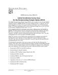
1
ACT Series Linear Motor
Actuator User’s Manual
P/N: EDS171 (Revision 1.01.00)
Dedicated to the Science of Motion
Aerotech, Inc.
101 Zeta Drive,
Pittsburgh, PA, 15238
Phone: 412-963-7470
Fax: 412-963-7459
www.aerotech.com
Product Registration
Register online at: http://www.aerotech.com/prodreg.cfm
Technical Support
United States Headquarters:
Phone: (412) 967-6440
Fax: (412) 967-6870
Email: [email protected]
United Kingdom:
Phone: +44 118 940 9400
Fax: +44 118 940 9401
Email: [email protected]
Germany:
Phone: +49 911 967 9370
Fax: +49 911 967 93720
Email: [email protected]
Japan:
Phone: +81(0)47-489-1741 (Sales)
Phone: +81(0)47-489-1742 (Service)
Fax: +81(0)47-489-1743
Email: [email protected]
China:
Phone: +852-3793-3488
Email: [email protected]
Revision History
1.01.00
December 30, 2011
1.00.00
May 20, 2011
N O T E : This manual and any additional instructions included with the ACT should be read in their entirety
before operating the ACT .
N O T E : Product names mentioned herein are used for identification purposes only and may be trademarks
of their respective companies.
Copyright © 2011 - 2012, Aerotech, Inc. All Rights Reserved.
ACT Series Linear Actuator User's Manual
Table of Contents
Table of Contents
Table of Contents
List of Figures
List of Tables
iii
v
vii
Chapter 1: Overview
1
1.1. Standard Features
1.1.1. Optional Features
1.1.2. Model Numbers
1.2. Dimensions
1.3. Safety Procedures and Warnings
1.4. EC Declaration of Incorporation
Chapter 2: Installation
2.1. Unpacking and Handling the Linear Motor Actuator
2.2. Preparing the Mounting Surface
2.3. Securing the Stage to the Mounting Surface
2.4. Attaching the Payload to the Linear Actuator
2.5. Bulkhead Connector Bracket Installation
2.6. Electrical Installation
2.7. Electrical Cable Strain Relief
2.8. Air Requirements
2
3
4
6
9
10
11
12
13
14
15
16
19
20
21
Chapter 3: Operating Specifications
23
3.1. Environmental Specifications
3.2. Accuracy and Temperature Effects
3.3. Basic Specifications
3.4. Load Capability
3.5. End of Travel Limits
3.5.1. Limit Operation
3.5.2. Limit Switch Wiring
3.5.3. Adjustable Limits
3.6. Standard Motor Wiring
3.7. Vacuum Operation
23
23
24
34
40
40
40
41
44
46
Chapter 4: Maintenance
4.1. Service and Inspection Schedule
4.2. Cleaning and Lubrication
4.2.1. Recommended Cleaning Solvents and Lubricants
4.2.2. Important Notes on Cleaning and Lubrication
4.2.3. Cleaning and Lubrication Process
47
47
48
48
48
49
Appendix A: Warranty and Field Service
51
Appendix B: Technical Changes
53
Index
55
Reader's Comments
57
www.aerotech.com
iii
Table of Contents
iv
ACT Series Linear Actuator User's Manual
www.aerotech.com
ACT Series Linear Actuator User's Manual
List Of Figures
List of Figures
Figure 1-1:
Figure 1-2:
Figure 1-3:
Figure 1-4:
Figure 1-5:
Figure 1-6:
Figure 2-1:
Figure 2-2:
Figure 2-3:
Figure 2-4:
Figure 2-5:
Figure 2-6:
Figure 2-7:
Figure 2-8:
Figure 3-1:
Figure 3-2:
Figure 3-3:
Figure 3-4:
Figure 3-5:
Figure 3-6:
Figure 3-7:
Figure 3-8:
Figure 3-9:
Figure 3-10:
Figure 3-11:
Typical ACT Series Linear Motor Actuator
ACT Series Linear Motor Actuator
Examples of Optional Features
ACT115DL Series Linear Motor Actuator Dimensions
ACT140DL Series Linear Motor Actuator Dimensions
ACT165DL Series Linear Motor Actuator Dimensions
Lifting Features
Results of Flat Versus Non-Flat Mounting
Bulkhead Bracket Installation — Jacksocket Disassembly
Bulkhead Bracket Installation — Attachment of Bracket to Carriage
Bulkhead Bracket Installation — Connector Assembly
Bulkhead Bracket Installation — Air Fittings Assembly
Motor and Feedback Connections
Example of an Electrical Cable Strain Relief
ACT115DL Cantilevered Load Capability
ACT140DL Cantilevered Load Capability
ACT165DL Cantilevered Load Capability
Cantilevered Load Diagram
ACT115DL Acceleration vs. Mass
ACT140DL Acceleration vs. Mass
ACT165DL Acceleration vs. Mass
Limit Switch Wiring
Adjustment of Moveable Limits
Acceptable Locations for Moveable Limits
Stacked Moveable Limits
www.aerotech.com
1
2
3
6
7
8
12
13
16
17
17
18
19
20
34
35
35
36
37
38
39
40
41
42
43
v
List of Figures
vi
ACT Series Linear Actuator User's Manual
www.aerotech.com
ACT Series Linear Actuator User's Manual
List of Tables
List of Tables
Table 1-1:
Table 3-1:
Table 3-2:
Table 3-3:
Table 3-4:
Table 3-5:
Table 3-6:
Table 3-7:
Table 3-8:
Table 3-9:
Table 3-10:
Table 3-11:
Table 3-12:
Table 3-13:
Table 3-14:
Table 3-15:
Table 3-16:
Table 3-17:
Table B-1:
Table B-2:
Model Numbers and Ordering Options
Environmental Specifications
ACT115DL Series Mechanical Specifications (-0100 to -0500)
ACT115DL Series Mechanical Specifications (-0600 to -1500)
ACT115DL Series Electrical Specifications
ACT140DL Series Mechanical Specifications (-0100 to -0500)
ACT140DL Series Mechanical Specifications (-0600 to -1500)
ACT140DL Series Electrical Specifications
ACT165DL Series Mechanical Specifications (-0100 to -0500)
ACT165DL Series Mechanical Specifications (-0600 to -1500)
ACT165DL Series Electrical Specifications
ACT Series Resolution Information
BLMC-142-A Motor Specifications
BLM-142-A Motor Specifications
BLMH-142-A Motor Specifications
Maximum Horizontal Load Capacity per ACT Model
Motor Connector Pin Assignments
Feedback Connector Pin Assignments
Current Changes (1.01.00)
Archived Changes
www.aerotech.com
4
23
24
25
25
26
27
27
28
29
29
30
31
32
33
34
44
45
53
54
vii
List of Tables
viii
ACT Series Linear Actuator User's Manual
www.aerotech.com
ACT Series Linear Actuator User's Manual
Overview
Chapter 1: Overview
This manual describes Aerotech’s ACT series of linear motor actuators. Figure 1-1 shows a typical ACT linear motor actuator.
The ACT is a high performance, cost-effective, linear-servomotor-driven actuator that is faster and more accurate than a ball screw or belt-drive actuator. The ACT is ideal for applications including assembly, pick and
place machines, electronic assembly and qualification, packaging, vision inspection, dispensing, life
sciences, image scanning and processing, and inkjet printing.
The ACT series supports travel distances ranging from 100 mm to 1500 mm.
This chapter introduces standard and optional features of the ACT linear motor actuators and gives general
safety precautions.
Figure 1-1:
Typical ACT Series Linear Motor Actuator
N O T E : Aerotech continually improves its product offerings; listed options may be superseded at any
time. Refer to the most recent edition of the Aerotech Motion Control Product Guide for the most current
product information at www.aerotech.com.
www.aerotech.com
Chapter 1
1
Overview
ACT Series Linear Actuator User's Manual
1.1. Standard Features
The ACT series incorporates a linear motion guide (LMG), a high power cog-free linear motor, and a high
accuracy non-contact linear optical encoder as standard features to provide a high performance, cost-effective linear actuator that is virtually maintenance-free. Because the ACT actuators consist of non-contact linear motors and encoders, there is no backlash, windup or wear that is normally associated with contactingtype systems such as ball screws or belt drives.
Limit switches and mechanical stops, which protect the carriage from over-travel, are also standard features
of every ACT linear motor actuator.
Figure 1-2:
2
ACT Series Linear Motor Actuator
Chapter 1
www.aerotech.com
ACT Series Linear Actuator User's Manual
Overview
1.1.1. Optional Features
Available assembly options allow the ACT series linear motor actuators to be configured for a variety of applications.
The non-contact linear optical encoder is available with either a line-driver output or an amplified sine-wave
output for maximum application flexibility. Various resolutions and clock rates are available upon request for
encoders with line-driver outputs.
For applications requiring the easy adjustment of useable travel, the ACT series linear motor actuators can be
equipped with optional moveable limits.
A bulkhead termination bracket option is available for OEM or applications requiring user-defined cable management. In cases where a complete solution is needed, an optional cable management chain can be provided.
Optional air cooling of the linear motor is offered for high duty cycle and heavy payload applications.
For critical applications, an option is available to verify the accuracy and repeatability performance of the
ACT linear motor actuator by performing metrology testing at the factory. In addition, a linear error correction
option is offered for those applications requiring the highest level of accuracy.
Aesthetic end plates are also available for all models of the ACT series linear motor actuators.
Refer to Figure 1-3 for examples of some of the optional features available on the ACT linear motor actuators.
Figure 1-3:
www.aerotech.com
Examples of Optional Features
Chapter 1
3
Overview
ACT Series Linear Actuator User's Manual
1.1.2. Model Numbers
The following table provides an ordering example for a typical ACT linear motor actuator and a list of available options. Aerotech continually improves its product offerings, and listed options can be superseded at
any time. For the most current product information, see the most recent edition of the Aerotech Motion Control Product Guide at www.aerotech.com.
Table 1-1:
Model Numbers and Ordering Options
ACTxxxDL Series Linear Motor Actuator
ACT115DL
ACT140DL
ACT165DL
Linear actuator with BLMC-142-A motor
Linear actuator with BLM-142-A motor
Linear actuator with BLMH-142-A motor
Travel
-0100
-0200
-0300
-0400
-0500
-0600
-0800
-1000
-1200
-1500
100 mm travel linear motor actuator
200 mm travel linear motor actuator
300 mm travel linear motor actuator
400 mm travel linear motor actuator
500 mm travel linear motor actuator
600 mm travel linear motor actuator
800 mm travel linear motor actuator
1000 mm travel linear motor actuator
1200 mm travel linear motor actuator
1500 mm travel linear motor actuator
Tabletop
-TTM
Metric dimension mounting pattern and holes (standard)
Standard Linear Feedback
-AS
-0.1
-0.5
Linear optical encoder; 20 µm/Vpp output
Linear optical encoder; 0.1 µm line driver output
Linear optical encoder; 0.5 µm line driver output
Limits
-NC-5V
-NCA-5V
5 V normally-closed end of travel limit switches with fixed locations (standard)
5 V normally-closed end of travel limit switches with adjustable location
Cable Management
-CONN-NH
-CONN-H
-CMSXXXX-H
4
150 mm (6 inch) connectorized leads from carriage; no cable management system; no linear motor Halls
150 mm (6 inch) connectorized leads from carriage; no cable management system; linear
motor Halls
Cable management system for 100 mm to 1500 mm single-axis applications; linear motor
Halls
Chapter 1
www.aerotech.com
ACT Series Linear Actuator User's Manual
Overview
Table 1-1: Ordering Options (continued)
Options
-FC
-EP
-BRACKET
Includes air cooling of linear motor forcer (20 psi compressed air supply required)
End plates mounted on linear actuator base
Bulkhead bracket mounting kit for installing motor and feedback connectors onto carriage
(for use with -CONN-NH and -CONN-H options). Installation of kit by end user is required.
Metrology
-NO PLOTS
-PLOTS
No testing of stage; no performance plots provided
Accuracy and repeatability testing of uncalibrated stage; performance plots provided
Accessories (to be ordered as separate line item)
-HALAR
High-accuracy system; linear error correction for accuracy and repeatability
www.aerotech.com
Chapter 1
5
Overview
ACT Series Linear Actuator User's Manual
1.2. Dimensions
MOTOR &
FEEDBACK CABLES
150[6] LENGTH
FROM CARRIAGE
MOTOR &
FEEDBACK CABLES
150[6] LENGTH
FROM STAGE
CABLE MANAGEMENT: (-CONN) CONNECTORIZED LEADS
OPTIONS: (-FC) MOTOR COOLING &
(-BRACKET) BULKHEAD
CABLE MANAGEMENT:
(-CONN) CONNECTORIZED LEADS
CABLE MANAGEMENT: (-CMSXXXX) E-CHAIN
OPTIONS: (-EP) ENDPLATES &
(-FC) MOTOR COOLING
62.5
58.8
TYP
GROUND
CONNECTION
A
M4X0.7 8
(12) PLACES
12.5
TYP
25
SQR
6
TYP
25
115
75
180
16
TYP
OPTICAL
ENCODER
20
37.5
C/2
HARDSTOP
B/2
LIMIT
7.5
M6X1.0
(8) PLACES
100
A/2
NOMINAL
B
40
DETAIL A
(-TTM) TABLETOP
85
5.7 TYP
BOTH SIDES
(-EP) OPTION
D
7.5 TYP
STAGE
MOUNTING
152.4[6.0]
7.0[
.276] THRU
(E) PLACES
50
50
END VIEW
(-BRACKET) BULKHEAD
END VIEW
(-CMSXXXX) E-CHAIN
76.2[3.0]
101.6[4.0]
TYP
50
SHOWN: ACT115DL-0300
100
101.6[4.0]
7.5
TYP
6.7
TYP
100
TYP
DETAIL B
(-NCA-5V) ADJUSTABLE LIMITS
50
100
WHEN (-FC) OPTION IS ORDERED W/:
- (-CONN) OR (-CMSXXXX) OPTIONS, THE AIR COOLING TUBE IS 4MM OD X 2.5MM ID
- (-BRACKET) OPTION, THE BARB FITTING SUPPORTS 6MM OD X 4MM ID TUBE
NOTE: OVERALL STAGE LENGTH INCREASES BY 11.4MM WITH (-EP) OPTION
D/2
MODEL #
A = NOMINAL
B = LIMIT
C = HARDSTOP
D = STAGE LENGTH
ACT115DL-0100
100
110
120
330
E = MOUNTING
8
ACT115DL-0200
200
210
220
430
16
ACT115DL-0300
300
310
320
530
16
ACT115DL-0400
400
410
420
630
24
ACT115DL-0500
500
510
520
730
24
ACT115DL-0600
600
610
620
830
32
ACT115DL-0800
800
810
820
1030
40
ACT115DL-1000
1000
1010
1020
1230
48
ACT115DL-1200
1200
1210
1220
1430
56
ACT115DL-1500
1500
1510
1520
1730
64
DIMENSIONS: MILLIMETERS[INCHES]
Figure 1-4:
6
ACT115DL Series Linear Motor Actuator Dimensions
Chapter 1
www.aerotech.com
ACT Series Linear Actuator User's Manual
Overview
MOTOR &
FEEDBACK CABLES
150[6] LENGTH
FROM CARRIAGE
CABLE MANAGEMENT:
(-CONN) CONNECTORIZED LEADS
MOTOR &
FEEDBACK CABLES
150[6] LENGTH
FROM STAGE
CABLE MANAGEMENT: (-CONN) CONNECTORIZED LEADS
OPTIONS: (-FC) MOTOR COOLING &
(-BRACKET) BULKHEAD
23.8
TYP
GROUND
65
CONNECTION
M6X1.0
9
TYP
(12) PLACES
A
CABLE MANAGEMENT: (-CMSXXXX) E-CHAIN
OPTIONS: (-EP) ENDPLATES &
(-FC) MOTOR COOLING
62.5
8
M4X0.7
(12) PLACES
16.5
TYP
12.5
TYP
25
140
100
6
TYP
50 SQR
75
240
25
TYP
20
OPTICAL
ENCODER
B/2
LIMIT
32.5
C/2
HARDSTOP
100
A/2
NOMINAL
150
45
TYP
110
DETAIL A
(-TTM) TABLETOP
B
115
8.5 TYP
BOTH SIDES
(-EP) OPTION
D
10 TYP
STAGE
MOUNTING
152.4[6.0]
7.0[
.276] THRU
(E) PLACES
50
50
END VIEW
(-BRACKET) BULKHEAD
END VIEW
(-CMSXXXX) E-CHAIN
76.2[3.0]
SHOWN: ACT140DL-0300
50
G TYP
125
127[5.0]
DETAIL B
(-NCA-5V) ADJUSTABLE LIMITS
7.5
TYP
6.5
TYP
F TYP
50
100
WHEN (-FC) OPTION IS ORDERED W/:
- (-CONN) OR (-CMSXXXX) OPTIONS, THE AIR COOLING TUBE IS 4MM OD X 2.5MM ID
- (-BRACKET) OPTION, THE BARB FITTING SUPPORTS 6MM OD X 4MM ID TUBE
NOTE: OVERALL STAGE LENGTH INCREASES BY 17MM WITH (-EP) OPTION
D/2
MODEL #
A = NOMINAL
B = LIMIT
C = HARDSTOP
D = STAGE LENGTH
E = MOUNTING
F = SPACING
ACT140DL-0100
100
105
120
390
16
75
G = SPACING
76.2[3.0]
ACT140DL-0200
200
205
220
490
16
100
101.6[4.0]
ACT140DL-0300
300
305
320
590
24
100
101.6[4.0]
ACT140DL-0400
400
405
420
690
24
100
101.6[4.0]
ACT140DL-0500
500
505
520
790
32
100
101.6[4.0]
ACT140DL-0600
600
605
620
890
32
100
101.6[4.0]
ACT140DL-0800
800
805
820
1090
40
100
101.6[4.0]
ACT140DL-1000
1000
1005
1020
1290
48
100
101.6[4.0]
ACT140DL-1200
1200
1205
1220
1490
56
100
101.6[4.0]
ACT140DL-1500
1500
1505
1520
1790
64
100
101.6[4.0]
DIMENSIONS: MILLIMETERS [INCHES]
Figure 1-5:
www.aerotech.com
ACT140DL Series Linear Motor Actuator Dimensions
Chapter 1
7
Overview
ACT Series Linear Actuator User's Manual
MOTOR &
FEEDBACK
CABLES
150[6] LENGTH
FROM
CARRIAGE
MOTOR &
FEEDBACK CABLES
150[6] LENGTH
FROM STAGE
CABLE MANAGEMENT: (-CONN) CONNECTORIZED LEADS
OPTIONS: (-FC) MOTOR COOLING &
(-BRACKET) BULKHEAD
23.8
GROUND
TYP
M6X1.0
9
CONNECTION
(12) PLACES
CABLE MANAGEMENT:
(-CONN) CONNECTORIZED LEADS
A
CABLE MANAGEMENT: (-CMSXXXX) E-CHAIN
OPTIONS: (-EP) ENDPLATES &
(-FC) MOTOR COOLING
M4X0.7
8
(12) PLACES
62.5
12.5
TYP
50
16.5
TYP
6
TYP
165
150 SQR
50 SQR
100 SQR
240
32.5
7.5
OPTICAL
ENCODER
B
65
TYP
C/2
HARDSTOP
B/2
LIMIT
110
TYP
45
TYP
DETAIL A
(-TTM) TABLETOP
A/2
NOMINAL
145
8.5 TYP
BOTH SIDES
(-EP) OPTION
D
60.5
END VIEW
(-BRACKET) BULKHEAD
12 TYP
STAGE
MOUNTING
152.4 6.00
7 .277 THRU
(E) PLACES
50
END VIEW
(-CMSXXXX) E-CHAIN
76.2 3.00
SHOWN: ACT165DL-0300
G TYP
50
152.4 6.00
150
F TYP
7.5
TYP
DETAIL B
(-NCA-5V) ADJUSTABLE LIMITS
6.3
TYP
50
100
WHEN (-FC) OPTION IS ORDERED W/:
- (-CONN) OR (-CMSXXXX) OPTIONS, THE AIR COOLING TUBE IS 6MM OD X 4MM ID
- (-BRACKET) OPTION, THE BARB FITTING SUPPORTS 6MM OD X 4MM ID TUBE
NOTE: OVERALL STAGE LENGTH INCREASES BY 17MM WITH (-EP) OPTION
D/2
MODEL #
A = NOMINAL
B = LIMIT
C = HARDSTOP
D = STAGE LENGTH
E = MOUNTING
F = SPACING
ACT165DL-0100
100
105
120
395
16
75
76.2[3.00]
ACT165DL-0200
200
205
220
495
16
100
101.6[4.00]
ACT165DL-0300
300
305
320
595
24
100
101.6[4.00]
ACT165DL-0400
400
405
420
695
24
100
101.6[4.00]
ACT165DL-0500
500
505
520
795
32
100
101.6[4.00]
ACT165DL-0600
600
605
620
895
32
100
101.6[4.00]
ACT165DL-0800
800
805
820
1095
40
100
101.6[4.00]
ACT165DL-1000
1000
1005
1020
1295
48
100
101.6[4.00]
ACT165DL-1200
1200
1205
1220
1495
56
100
101.6[4.00]
ACT165DL-1500
1500
1505
1520
1795
64
100
101.6[4.00]
G = SPACING
DIMENSIONS: MILLIMETERS [INCHES]
Figure 1-6:
8
ACT165DL Series Linear Motor Actuator Dimensions
Chapter 1
www.aerotech.com
ACT Series Linear Actuator User's Manual
Overview
1.3. Safety Procedures and Warnings
The following statements apply wherever the Warning or Danger symbol appears within this manual. Failure
to observe these precautions could result in serious injury to those individuals performing the procedures
and/or damage to the equipment. Operators should be trained before operating this equipment.
D A N G E R : To minimize the possibility of electrical shock and bodily injury or death, disconnect all electrical power prior to making any electrical connections.
D A N G E R : To minimize the possibility of electrical shock and bodily injury or death when any
electrical circuit is in use, ensure that no person comes in contact with the circuitry when the
ACT is connected to a power source.
D A N G E R : To minimize the possibility of bodily injury or death, disconnect all electrical power
prior to making any mechanical adjustments.
D A N G E R : Moving parts of the ACT can cause crushing or shearing injuries. All personnel
must remain clear of any moving parts.
W A R N I N G : Improper use of the linear motor actuator can cause damage, shock, injury, or
death. Read and understand this manual before operating the linear motor actuator.
W A R N I N G : Cables can pose a tripping hazard. Securely mount and position all ACT cables
to avoid potential hazards.
W A R N I N G : Do not expose the ACT to environments or conditions outside the specified
range of operating environments. Operation in conditions other than those specified can cause
damage to the equipment.
W A R N I N G : The ACT must be mounted securely. Improper mounting can result in injury and
damage to the equipment.
W A R N I N G : Use care when moving the ACT. Manually lifting or transporting the ACT can
result in injury.
W A R N I N G : Only trained personnel should operate, inspect, and maintain the ACT.
W A R N I N G : This ACT is intended for light industrial manufacturing or laboratory use. Use of
the ACT for unintended applications can result in injury and damage to the equipment.
W A R N I N G : Before using this ACT, perform an operator risk assessment to determine the
needed safety requirements.
www.aerotech.com
Chapter 1
9
Overview
ACT Series Linear Actuator User's Manual
1.4. EC Declaration of Incorporation
Manufacturer:
Aerotech, Inc.
101 Zeta Drive
Pittsburgh, PA 15238
USA
herewith declares that the product:
Aerotech, Inc. ACT Linear Motor Actuator
is intended to be incorporated into machinery to constitute machinery covered by the Directive
2006/42/EC as amended;
does therefore not in every respect comply with the provisions of this directive;
and that the following harmonized European standards have been applied:
EN ISO 12100-1,-2:2003+A1:2009
Safety of machinery - Basic concepts, general principles for design
ISO 14121-1:2007
Safety of machinery - Risk assessment - Par 1: Principles
EN 60204-1:2005
Safety of machinery - Electrical equipment of machines - Part 1: General requirements
and further more declares that
it is not allowed to put the equipment into service until the machinery into which it
is to be incorporated or of which it is to be a component has been found and
declared to be in conformity with the provisions of the Directive 2006/42/EC and
with national implementing legislation, i.e. as a whole, including the equipment
referred to in this Declaration.
Authorized Representative:
Address:
Manfred Besold
AEROTECH GmbH
Süd-West-Park 90
D-90449 Nürnberg
Name:
Position:
Location:
Date:
10
Alex Weibel /
Engineer Verifying Compliance
Pittsburgh, PA
December 30, 2011
Chapter 1
www.aerotech.com
ACT Series Linear Actuator User's Manual
Installation
Chapter 2: Installation
This chapter describes the installation procedure the ACT series linear motor actuators, including handling
the linear motor actuator correctly, securing the linear motor actuator to the mounting surface, attaching the
payload, and making the electrical connections.
W A R N I N G : Installation must follow the instructions in this chapter. Failure to follow these
instructions could result in injury and damage to the equipment.
www.aerotech.com
Chapter 2
11
Installation
ACT Series Linear Actuator User's Manual
2.1. Unpacking and Handling the Linear Motor Actuator
Carefully remove the linear motor actuator from the protective shipping container. Most ACT series linear
motor actuators come equipped with lifting features attached to the base, as shown in Figure 2-1. Use these
lifting features in conjunction with lifting straps to handle the linear motor actuator. If lifted by hand, the linear
motor actuator should be lifted from the bottom of the base. Do not attempt to lift or move the linear motor
actuator by the carriage, cable brackets or end plates. For multi-axis assemblies, always lift the system by
the lower axis. Lifting by the upper axis can disturb precision alignments on the system.
Figure 2-1:
Lifting Features
Each ACT has a label listing the system part number and serial number. These numbers contain information
necessary for maintaining or updating system hardware and software. Locate this label and record the information for later reference. If any damage has occurred during shipping, report it immediately.
W A R N I N G : Improper handling could adversely affect the ACT’s performance. Use care when
moving the stage.
W A R N I N G : Use care when moving the ACT. Manually lifting or transporting the ACT can
result in injury.
W A R N I N G : Lift the ACT only by the base.
12
Chapter 2
www.aerotech.com
ACT Series Linear Actuator User's Manual
Installation
2.2. Preparing the Mounting Surface
The mounting surface should be flat and have adequate stiffness in order to achieve the maximum performance from the ACT. When an ACT series linear motor actuator is mounted to a non-flat surface, the linear motor actuator can be distorted as the mounting screws are tightened. This distortion will decrease the
overall accuracy of the linear motor actuator. Adjustments to the mounting surface must be done before the
linear motor actuator is secured. The effects of flatness on mounting are illustrated in Figure 2-2.
N O T E : To maintain accuracy, the mounting surface should be flat within 15 µm per 150 mm.
Figure 2-2:
Results of Flat Versus Non-Flat Mounting
N O T E : The ACT base is precision machined and verified for flatness prior to product assembly at the factory. If machining is required to achieve the desired flatness, it should be performed on the mounting surface rather than the ACT base. Shimming should be avoided if possible. If shimming is required, it should
be minimized to improve the rigidity of the system.
www.aerotech.com
Chapter 2
13
Installation
ACT Series Linear Actuator User's Manual
2.3. Securing the Stage to the Mounting Surface
D A N G E R : Strong rare-earth magnets are present in the linear motor magnet track. Loose
metal objects (tools, watches, keys, etc.) may cause personal injury and/or damage to the equipment.
W A R N I N G : The ACT must be mounted securely. Improper mounting can result in injury and
damage to the equipment.
Procedure for ACT linear motor actuator mounting:
1. Prepare the mounting surface and bottom of the linear motor actuator base by stoning with precision flat
stones to remove any burrs or high spots.
2. Clean the mounting surface and bottom of the linear motor actuator with the appropriate cleaners (isopropyl alcohol for the bottom of the linear motor actuator).
3. Place the linear motor actuator on the mounting surface.
4. Remove the lifting features and shipping brackets (refer to Figure 2-1). The lifting features consist of the
eyebolts that are directly threaded into the linear motor actuator base through standoff spaces. They can
be removed by tightening a wrench on the head of the eyebolt.
W A R N I N G : Do not attempt to move the ACT's carriage (or table top) until the lifting brackets
and shipping brackets have been removed. Moving the carriage with the lifting brackets and shipping brackets installed can cause permanent damage to the ACT.
N O T E : After removing the lifting features or shipping brackets, retain them for future use. In the event that
the product requires service at the factory, the lifting features or shipping brackets should be reattached to
ensure that the ACT ships safely.
5. If necessary, manually move the carriage to access the 7 mm (0.28 in) diameter mounting holes along
the edges of the base. The ACT linear motor actuators are designed to use socket head cap screws
(SHCS) to secure the base to the mounting surface. Use either M6 or 1/4" SHCS with flat washers to
provide at least 1.5x diameter thread engagement. Tighten the mounting screws to 8 N-m (6 ft-lb) torque.
W A R N I N G : Do not attempt to manually move the linear motor actuator if it is connected to a
power source.
14
Chapter 2
www.aerotech.com
ACT Series Linear Actuator User's Manual
Installation
2.4. Attaching the Payload to the Linear Actuator
To prevent damage to payloads, test the operation of the linear motor actuator before the payload is attached
to the carriage. Proceed with the electrical installation and test the motion control system in accordance with
the system documentation. Document all results for future reference. For information on electrical connections, refer to Section 2.6. and the documentation delivered with the stage.
The payload should be flat, rigid, and comparable to the linear motor actuator in quality.
N O T E : For valid system performance, the mounting interface should be flat within 5 µm per 50 mm.
www.aerotech.com
Chapter 2
15
Installation
ACT Series Linear Actuator User's Manual
2.5. Bulkhead Connector Bracket Installation
These instructions apply only to those linear motor actuators that have been supplied with a -BRACKET bulkhead bracket mounting kit. The -BRACKET bulkhead mounting kid provides the user with the necessary
hardware for mounting the motor and feedback connectors directly onto the carriage of any linear motor
actuator constructed with either the -CONN-H or -CONN-NH cable management options.
Note that installation and use of the -BRACKET bulkhead mounting kit along does not constitute a correct
electrical cable strain relief as described in Section 2.7. The user must still implement a correct electrical
cable strain relief, or premature failure of the linear motor actuator and damage to the equipment can result.
Procedure for -BRACKET bulkhead mounting kit installation:
1. Disassemble the jacksockets from the linear motor actuator's motor power and feedback connectors
(refer to Figure 2-3). These jacksockets can be discarded after removal.
2. Attach the bulkhead connector bracket to the carriage using the M4 x 8 mm long button head socket cap
screws (BHCS) provided (refer to Figure 2-4).
3. Attach the linear motor actuator's motor power and feedback connectors to the bulkhead connector
bracket using the jacksockets provided (refer to Figure 2-5).
4. If the linear motor actuator is equipped with the -FC linear motor forcer cooling option, install the barbed
air fittings provided in the kit onto the bulkhead connector bracket. Use the small barbed air fitting with
the ACT115DL and ACT140DL models. Use the large barbed air fitting with the ACT165DL models.
Attach the air hose from the linear motor actuator’s carriage onto the appropriate barbed fitting (refer to
Figure 2-6).
Figure 2-3:
16
Bulkhead Bracket Installation — Jacksocket Disassembly
Chapter 2
www.aerotech.com
ACT Series Linear Actuator User's Manual
Figure 2-4:
Installation
Bulkhead Bracket Installation — Attachment of Bracket to Carriage
Figure 2-5:
www.aerotech.com
Bulkhead Bracket Installation — Connector Assembly
Chapter 2
17
Installation
ACT Series Linear Actuator User's Manual
Figure 2-6:
18
Bulkhead Bracket Installation — Air Fittings Assembly
Chapter 2
www.aerotech.com
ACT Series Linear Actuator User's Manual
Installation
2.6. Electrical Installation
Electrical installation requirements vary depending on linear motor actuator options. Installation instructions
in this section are for linear motor actuators equipped with standard Aerotech linear motors intended for use
with an Aerotech motion control system. Contact Aerotech for further information regarding linear motor actuators that are otherwise configured.
Aerotech motion control systems are adjusted at the factory for optimum performance. When the ACT series
linear motor actuator is part of a complete Aerotech motion control system, setup involves connecting a linear
motor actuator to the appropriate drive chassis with the cables provided. Labels on the system components
indicate the appropriate connections. However, refer to your drive manuals and documentation for additional
installation and operation information. In some cases, if the system is uniquely configured, a drawing showing system interconnects is supplied.
A linear motor and a linear encoder are standard for all ACT series actuators. The electrical wiring from the
motor and encoder are integrated into two main connectors at the factory, as shown in Figure 2-7. Refer to
Section 3.6. for standard wiring pinouts.
W A R N I N G : Never connect or disconnect any electrical component or connecting cable while
power is applied, or serious damage can result.
W A R N I N G : The stage's protective ground is located on pin A4 of the motor connector. If you
are using cables other than those provided by Aerotech, you must connect pin A4 to a ground
connection.
Figure 2-7:
www.aerotech.com
Motor and Feedback Connections
Chapter 2
19
Installation
ACT Series Linear Actuator User's Manual
2.7. Electrical Cable Strain Relief
The user must provide an electrical cable strain relief for any ACT linear motor actuator that is constructed
with either the -CONN-H or -CONN-NH cable management options (refer to Figure 2-8 for an example). Failure to implement a correct electrical cable strain relief can result in premature failure of the linear motor actuator and/or damage to the equipment. The -CMSXXXX-H option is recommended for applications requiring a
complete cable management solution.
Figure 2-8:
20
Example of an Electrical Cable Strain Relief
Chapter 2
www.aerotech.com
ACT Series Linear Actuator User's Manual
Installation
2.8. Air Requirements
An air supply is only needed for those ACT models that are equipped with the -FC linear motor forcer cooling
option. Compressed air at a pressure of 138 kPa (20 psi) is required when using this feature. For the ACT
115DL and ACT 140DL linear motor actuators, it is recommended that air be supplied via a polyurethane air
hose with an inner diameter of 2.5 mm (3/32”) or larger. For the ACT 165DL linear motor actuator, it is recommended that air be supplied via a polyurethane air hose with an inner diameter of 4 mm (5/32”) or larger.
See Table 3-12, Table 3-13, and Table 3-14 for typical forcer cooling air flow rates.
www.aerotech.com
Chapter 2
21
Installation
22
ACT Series Linear Actuator User's Manual
Chapter 2
www.aerotech.com
ACT Series Linear Actuator User's Manual
Operating Specifications
Chapter 3: Operating Specifications
The surrounding environment and operating conditions can affect the performance and service life of the linear actuator. This chapter provides information on ideal environmental and operating conditions. Also
included are instructions for estimating the load capability given various loadings.
3.1. Environmental Specifications
The environmental specifications for the ACT are listed in the following table.
Table 3-1:
Environmental Specifications
Ambient
Temperature
Operating: 10° to 35° C (50° to 95° F)
The optimal operating temperature is 20° C ±2° C (68° F ±4° F). If at any time the operating temperature deviates from 20° C degradation in performance could occur. Contact Aerotech for
information regarding your specific application and environment.
Storage: 0° to 40° C (32° to 104° F) in original shipping packaging
Humidity
Operating: 40 percent to 60 percent RH
The optimal operating humidity is 50 percent RH.
Storage: 30 percent to 60 percent RH, non-condensing in original packaging
Altitude
Operating: 0 to 2,000 m (0 to 6,562 ft) above sea level
Contact Aerotech if your specific application involves use above 2,000 m or below sea level.
Vibration
Use the system in a low vibration environment. Excessive floor or acoustical vibration can affect
linear actuator and system performance. Contact Aerotech for information regarding your specific application.
Dust Exposure
The ACT linear motor actuators are not suited for dusty or wet environments. This equates to an
ingress protection rating of IP00.
Use
Indoor use only
W A R N I N G : Do not expose the ACT to environments or conditions outside the specified
range of operating environments. Operation in conditions other than those specified can cause
damage to the equipment.
3.2. Accuracy and Temperature Effects
When an ACT series linear motor actuator is ordered with the -PLOTS metrology option, the accuracy specification is measured at the center of the carriage, 25 mm above the carriage’s mounting surface, with the linear motor actuator in a horizontal orientation. The linear motor actuator is assumed to be fully supported by a
mounting surface that meets or exceeds the specification described in Section 2.2.
The accuracy specifications listed in Section 3.3. assume a 20º C operating environment. If the temperature
of the linear motor actuator differs from 20º C, then the encoder scale mounted directly to the linear motor
actuator’s base will expand or contract at a rate of 23.6 ppm per °C.
www.aerotech.com
Chapter 3
23
Operating Specifications
ACT Series Linear Actuator User's Manual
3.3. Basic Specifications
Basic specifications provided in this section include: mechanical and electrical specifications, encoder resolution information, and BLMC-142, BLM-142, and BLMH-142 motor specifications.
For the most recent specifications, see www.aerotech.com.
Table 3-2:
ACT115DL Series Mechanical Specifications (-0100 to -0500)
Mechanical Specifications
Travel
Accuracy(1)
Uncalibrated
Calibrated(2)
Resolution
Repeatability (BiDirectional)(1,3)
Maximum Speed(4)
Maximum Acceleration (Continuous)(4)
Maximum
20 psi
Force (ConNo Air
tinuous)
Horizontal
Load
Capacity(5)
Side
Moving Mass
Stage Mass
Material
MTBF (Mean Time Between
Failure)
Drive System
-0100
-0200
100 mm
±7 µm
±2 µm
200 mm
±13 µm
±2 µm
ACT115DL
-0300
300 mm
±19 µm
±2 µm
0.005 - 1 µm
±1 µm
-0400
-0500
400 mm
±25 µm
±2 µm
500 mm
±31 µm
±3 µm
5 m/s
3g
120.3 N
77.7 N
20 kg
10 kg
1.4 kg
7.3 kg
9.1 kg
10.9 kg
12.7 kg
14.5 kg
Aluminum (Clear Anodize Base/Black Anodize Tabletop)
20,000 Hours
Brushless Linear Servomotor (BLMC-142-A)
1. Testing conducted only when “-PLOTS” metrology option is ordered.
2. Calibration available with HALAR option.
3. Bi-directional repeatability specification listed requires resolution of 0.1 µm or finer. Specification is ±2 µm with resolution of 0.5 µm.
Coarser resolutions will result in reduced bi-directional repeatability performance.
4. Maximum velocity and acceleration specifications assume a small payload. As payload increases, the maximum attainable velocity
and acceleration will decrease. Maximum application velocity may be limited by system data rate and resolution.
5. Axis orientation for on-axis loading is listed.
6. Specifications are for single-axis systems measured 25 mm above the tabletop. Consult factory for non-standard applications.
24
Chapter 3
www.aerotech.com
ACT Series Linear Actuator User's Manual
Table 3-3:
ACT115DL Series Mechanical Specifications (-0600 to -1500)
Mechanical Specifications
Travel
Accuracy(1)
Operating Specifications
Uncalibrated
Calibrated(2)
Resolution
Repeatability (BiDirectional)(1,3)
Maximum Speed(4)
Maximum Acceleration (Continuous)(4)
Maximum
20 psi
Force (ConNo Air
tinuous)
Horizontal
Load
Capacity(5)
Side
Moving Mass
Stage Mass
Material
MTBF (Mean Time Between
Failure)
Drive System
-0600
-0800
600 mm
±36 µm
±3 µm
800 mm
±44 µm
±3 µm
ACT115DL
-1000
1000 mm
±50 µm
±5 µm
0.005 - 1 µm
±1 µm
-1200
-1500
1200 mm
±55 µm
±5 µm
1500 mm
±60 µm
±5 µm
5 m/s
3g
120.3 N
77.7 N
20 kg
10 kg
1.4 kg
16.3 kg
20.0 kg
23.6 kg
27.2 kg
32.7 kg
Aluminum (Clear Anodize Base/Black Anodize Tabletop)
20,000 Hours
Brushless Linear Servomotor (BLMC-142-A)
1. Testing conducted only when “-PLOTS” metrology option is ordered.
2. Calibration available with HALAR option.
3. Bi-directional repeatability specification listed requires resolution of 0.1 µm or finer. Specification is ±2 µm with resolution of 0.5 µm.
Coarser resolutions will result in reduced bi-directional repeatability performance.
4. Maximum velocity and acceleration specifications assume a small payload. As payload increases, the maximum attainable velocity
and acceleration will decrease. Maximum application velocity may be limited by system data rate and resolution.
5. Axis orientation for on-axis loading is listed.
6. Specifications are for single-axis systems measured 25 mm above the tabletop. Consult factory for non-standard applications.
Table 3-4:
ACT115DL Series Electrical Specifications
Electrical Specifications
ACT115DL
Feedback
Maximum Bus Voltage
Limit Switches
Home Switch
www.aerotech.com
Noncontact Linear Encoder
320 VDC
5 V, Normally Closed
Near Center
Chapter 3
25
Operating Specifications
Table 3-5:
ACT140DL Series Mechanical Specifications (-0100 to -0500)
Mechanical Specifications
Travel
Accuracy(1)
ACT Series Linear Actuator User's Manual
Uncalibrated
Calibrated(2)
Resolution
Repeatability (BiDirectional)(1,3)
Maximum Speed(4)
Maximum Acceleration (Continuous)(4)
Maximum
20 psi
Force (ConNo Air
tinuous)
Horizontal
Load
Capacity(5)
Side
Moving Mass
Stage Mass
Material
MTBF (Mean Time Between
Failure)
Drive System
-0100
-0200
100 mm
±7 µm
±2 µm
200 mm
±13 µm
±2 µm
ACT140DL
-0300
300 mm
±19 µm
±2 µm
0.005 - 1 µm
±1 µm
-0400
-0500
400 mm
±25 µm
±2 µm
500 mm
±31 µm
±3 µm
5 m/s
5g
173.2 N
110.5 N
40 kg
20 kg
2.5 kg
13.8 kg
17.0 kg
19.5 kg
22.7 kg
25.3 kg
Aluminum (Clear Anodize Base/Black Anodize Tabletop)
20,000 Hours
Brushless Linear Servomotor (BLM-142-A)
1. Testing conducted only when “-PLOTS” metrology option is ordered.
2. Calibration available with HALAR option.
3. Bi-directional repeatability specification listed requires resolution of 0.1 µm or finer. Specification is ±2 µm with resolution of 0.5 µm.
Coarser resolutions will result in reduced bi-directional repeatability performance.
4. Maximum velocity and acceleration specifications assume a small payload. As payload increases, the maximum attainable velocity
and acceleration will decrease. Maximum application velocity may be limited by system data rate and resolution.
5. Axis orientation for on-axis loading is listed.
6. Specifications are for single-axis systems measured 25 mm above the tabletop. Consult factory for non-standard applications.
26
Chapter 3
www.aerotech.com
ACT Series Linear Actuator User's Manual
Table 3-6:
ACT140DL Series Mechanical Specifications (-0600 to -1500)
Mechanical Specifications
Travel
Accuracy(1)
Operating Specifications
Uncalibrated
Calibrated(2)
Resolution
Repeatability (BiDirectional)(1,3)
Maximum Speed(4)
Maximum Acceleration (Continuous)(4)
Maximum
20 psi
Force (ConNo Air
tinuous)
Horizontal
Load
Capacity(5)
Side
Moving Mass
Stage Mass
Material
MTBF (Mean Time Between
Failure)
Drive System
-0600
-0800
600 mm
±36 µm
±3 µm
800 mm
±44 µm
±3 µm
ACT140DL
-1000
1000 mm
±50 µm
±5 µm
0.005 - 1 µm
±1 µm
-1200
-1500
1200 mm
±55 µm
±5 µm
1500 mm
±60 µm
±5 µm
5 m/s
5g
173.2 N
110.5 N
40 kg
20 kg
2.5 kg
28.5 kg
34.3 kg
40.7 kg
46.4 kg
55.4 kg
Aluminum (Clear Anodize Base/Black Anodize Tabletop)
20,000 Hours
Brushless Linear Servomotor (BLM-142-A)
1. Testing conducted only when “-PLOTS” metrology option is ordered.
2. Calibration available with HALAR option.
3. Bi-directional repeatability specification listed requires resolution of 0.1 µm or finer. Specification is ±2 µm with resolution of 0.5 µm.
Coarser resolutions will result in reduced bi-directional repeatability performance.
4. Maximum velocity and acceleration specifications assume a small payload. As payload increases, the maximum attainable velocity
and acceleration will decrease. Maximum application velocity may be limited by system data rate and resolution.
5. Axis orientation for on-axis loading is listed.
6. Specifications are for single-axis systems measured 25 mm above the tabletop. Consult factory for non-standard applications.
Table 3-7:
ACT140DL Series Electrical Specifications
Electrical Specifications
ACT140DL
Feedback
Maximum Bus Voltage
Limit Switches
Home Switch
www.aerotech.com
Noncontact Linear Encoder
320 VDC
5 V, Normally Closed
Near Center
Chapter 3
27
Operating Specifications
Table 3-8:
ACT165DL Series Mechanical Specifications (-0100 to -0500)
Mechanical Specifications
Travel
Accuracy(1)
ACT Series Linear Actuator User's Manual
Uncalibrated
Calibrated(2)
Resolution
Repeatability (BiDirectional)(1,3)
Maximum Speed(4)
Maximum Acceleration (Continuous)(4)
Maximum
20 psi
Force (ConNo Air
tinuous)
Horizontal
Load
Capacity(5)
Side
Moving Mass
Stage Mass
Material
MTBF (Mean Time Between
Failure)
Drive System
-0100
-0200
100 mm
±7 µm
±2 µm
200 mm
±13 µm
±2 µm
ACT165DL
-0300
300 mm
±19 µm
±2 µm
0.005 - 1 µm
±1 µm
-0400
-0500
400 mm
±25 µm
±2 µm
500 mm
±31 µm
±3 µm
5 m/s
5g
270.7 N
150.0 N
60 kg
30 kg
3.0 kg
23.4 kg
29.1 kg
33.4 kg
39.0 kg
44.7 kg
Aluminum (Clear Anodize Base/Black Anodize Tabletop)
20,000 Hours
Brushless Linear Servomotor (BLMH-142-A)
1. Testing conducted only when “-PLOTS” metrology option is ordered.
2. Calibration available with HALAR option.
3. Bi-directional repeatability specification listed requires resolution of 0.1 µm or finer. Specification is ±2 µm with resolution of 0.5 µm.
Coarser resolutions will result in reduced bi-directional repeatability performance.
4. Maximum velocity and acceleration specifications assume a small payload. As payload increases, the maximum attainable velocity
and acceleration will decrease. Maximum application velocity may be limited by system data rate and resolution.
5. Axis orientation for on-axis loading is listed.
6. Specifications are for single-axis systems measured 25 mm above the tabletop. Consult factory for non-standard applications.
28
Chapter 3
www.aerotech.com
ACT Series Linear Actuator User's Manual
Table 3-9:
ACT165DL Series Mechanical Specifications (-0600 to -1500)
Mechanical Specifications
Travel
Accuracy(1)
Operating Specifications
Uncalibrated
Calibrated(2)
Resolution
Repeatability (BiDirectional)(1,3)
Maximum Speed(4)
Maximum Acceleration (Continuous)(4)
Maximum
20 psi
Force (ConNo Air
tinuous)
Horizontal
Load
Capacity(5)
Side
Moving Mass
Stage Mass
Material
MTBF (Mean Time Between
Failure)
Drive System
-0600
-0800
600 mm
±36 µm
±3 µm
800 mm
±44 µm
±3 µm
ACT165DL
-1000
1000 mm
±50 µm
±5 µm
0.005 - 1 µm
±1 µm
-1200
-1500
1200 mm
±55 µm
±5 µm
1500 mm
±60 µm
±5 µm
5 m/s
5g
270.7 N
150.0 N
60 kg
30 kg
3.0 kg
48.9 kg
60.3 kg
70.2 kg
80.1 kg
95.7 kg
Aluminum (Clear Anodize Base/Black Anodize Tabletop)
20,000 Hours
Brushless Linear Servomotor (BLMH-142-A)
1. Testing conducted only when “-PLOTS” metrology option is ordered.
2. Calibration available with HALAR option.
3. Bi-directional repeatability specification listed requires resolution of 0.1 µm or finer. Specification is ±2 µm with resolution of 0.5 µm.
Coarser resolutions will result in reduced bi-directional repeatability performance.
4. Maximum velocity and acceleration specifications assume a small payload. As payload increases, the maximum attainable velocity
and acceleration will decrease. Maximum application velocity may be limited by system data rate and resolution.
5. Axis orientation for on-axis loading is listed.
6. Specifications are for single-axis systems measured 25 mm above the tabletop. Consult factory for non-standard applications.
Table 3-10:
ACT165DL Series Electrical Specifications
Electrical Specifications
ACT165DL
Feedback
Maximum Bus Voltage
Limit Switches
Home Switch
www.aerotech.com
Noncontact Linear Encoder
320 VDC
5 V, Normally Closed
Near Center
Chapter 3
29
Operating Specifications
Table 3-11:
ACT Series Linear Actuator User's Manual
ACT Series Resolution Information
Code
Signal Period
Travel/Step
Multiplier
-AS
-0.1
-0.5
20 µm
20 µm
20 µm
0.005 µm - 1.0 µm
0.1 µm
0.5 µm
Requires External
Integral x50
Integral x10
Code
Maximum Speed
Signal Type
Encoder Connector
-AS
System Data Rate (up to 5.0 m/s)
-0.1
1.3 m/s max (1)
-0.5
3.0 m/s max (1)
1. Requires system data rate of at least 24 MHz
30
Chapter 3
www.aerotech.com
ACT Series Linear Actuator User's Manual
Table 3-12:
Operating Specifications
BLMC-142-A Motor Specifications
Specifications
Performance Specifications
(1,5)
Continuous Force, 20 psi, 1.4 bar (2)
120.3 N
27.0 lb
77.7 N
17.5 lb
481.2 N
108.2 lb
Continuous Force, No Cooling, (2)
Peak Force (3)
Electrical Specifications (5)
BEMF Constant (line to line, max)
21.28 V / m / sec
0.54 V / in / sec
6.50 A, pk
4.60 A, rms
4.20 A, pk
2.97 A, rms
26.00 A, pk
18.38 A, rms
18.51 N / A, pk
4.16 lb / A, pk
26.17 N / A, rms
5.88 lb / A, rms
8.24 N / √W
1.85 lb / √W
4.8 Ohms
1.33 mH
0.47 °C / W
1.12 °C / W
340 VDC
Continuous Current, 20 psi, 1.4 bar (2)
Continuous Current, No Cooling (2)
Peak Current, Stall (3)
Force Constant, Sinusoidal Drive (4,8)
Motor Constant (2,4)
Resistance, 25 °C (line to line)
Inductance (line to line)
Thermal Resistance, 20 psi, 1.4 bar
Thermal Resistance, No Cooling
Maximum Bus Voltage
Mechanical Specifications (5)
1.7x10⁻³ m3/s
3.6 SCFM
25 mm
0.98 in
Air Flow, 20 psi
Magnetic Pole Pitch
1. Performance is dependent upon heat sink configuration, system cooling conditions, and ambient temperature
2. Values shown @ 100 °C rise above a 25 °C ambient temperature, with motor mounted to the specified aluminum heat sink
3. Peak force assumes correct rms current, consult Aerotech
4. Force Constant and Motor Constant specified at stall
5. All performance and electrical specifications +/- 10%
6. Maximum winding temperature is 125 °C
7. Ambient operating temperature range: 0 °C - 25 °C, consult Aerotech for performance in elevated ambient temperatures
8. All Aerotech amplifiers are rated Apk; use torque constant in N-m / Apk when sizing
www.aerotech.com
Chapter 3
31
Operating Specifications
Table 3-13:
ACT Series Linear Actuator User's Manual
BLM-142-A Motor Specifications
Specifications
Performance Specifications
(1,5)
Continuous Force, 20 psi, 1.4 bar (2)
173.2 N
38.9 lb
110.5 N
24.8 lb
692.7 N
155.7 lb
Continuous Force, No Cooling, (2)
Peak Force (3)
Electrical Specifications (5)
BEMF Constant (line to line, max)
40.96 V / m / sec
1.04 V / in / sec
4.86 A, pk
3.44 A, rms
3.10 A, pk
2.19 A, rms
19.44 A, pk
13.75 A, rms
35.63 N / A, pk
8.01 lb / A, pk
50.39 N / A, rms
11.33 lb / A, rms
10.53 N / √W
2.37 lb / √W
10.9 Ohms
8.70 mH
0.37 °C / W
0.91 °C / W
340 VDC
Continuous Current, 20 psi, 1.4 bar (2)
Continuous Current, No Cooling (2)
Peak Current, Stall (3)
Force Constant, Sinusoidal Drive (4,8)
Motor Constant (2,4)
Resistance, 25 °C (line to line)
Inductance (line to line)
Thermal Resistance, 20 psi, 1.4 bar
Thermal Resistance, No Cooling
Maximum Bus Voltage
Mechanical Specifications (5)
1.7x10⁻³ m3/s
3.5 SCFM
30.48 mm
1.20 in
Air Flow, 20 psi
Magnetic Pole Pitch
1. Performance is dependent upon heat sink configuration, system cooling conditions, and ambient temperature
2. Values shown @ 100 °C rise above a 25 °C ambient temperature, with motor mounted to the specified aluminum heat sink
3. Peak force assumes correct rms current, consult Aerotech
4. Force Constant and Motor Constant specified at stall
5. All performance and electrical specifications +/- 10%
6. Maximum winding temperature is 125 °C
7. Ambient operating temperature range: 0 °C - 25 °C, consult Aerotech for performance in elevated ambient temperatures
8. All Aerotech amplifiers are rated Apk; use torque constant in N-m / Apk when sizing
32
Chapter 3
www.aerotech.com
ACT Series Linear Actuator User's Manual
Table 3-14:
Operating Specifications
BLMH-142-A Motor Specifications
Specifications
Performance Specifications
(1,5)
Continuous Force, 20 psi, 1.4 bar (2)
270.7 N
60.9 lb
150.0 N
33.7 lb
1082.7 N
243.4 lb
Continuous Force, No Cooling, (2)
Peak Force (3)
Electrical Specifications (5)
BEMF Constant (line to line, max)
32.11 V / m / sec
0.82 V / in / sec
9.69 A, pk
6.85 A, rms
5.37 A, pk
3.80 A, rms
38.76 A, pk
27.41 A, rms
27.93 N / A, pk
6.28 lb / A, pk
39.50 N / A, rms
8.88 lb / A, rms
14.17 N / √W
3.19 lb / √W
3.7 Ohms
2.40 mH
0.27 °C / W
0.89 °C / W
340 VDC
Continuous Current, 20 psi, 1.4 bar (2)
Continuous Current, No Cooling (2)
Peak Current, Stall (3)
Force Constant, Sinusoidal Drive (4,8)
Motor Constant (2,4)
Resistance, 25 °C (line to line)
Inductance (line to line)
Thermal Resistance, 20 psi, 1.4 bar
Thermal Resistance, No Cooling
Maximum Bus Voltage
Mechanical Specifications (5)
2.5x10⁻³ m3/s
5.3 SCFM
30.00 mm
1.18 in
Air Flow, 20 psi
Magnetic Pole Pitch
1. Performance is dependent upon heat sink configuration, system cooling conditions, and ambient temperature
2. Values shown @ 100 °C rise above a 25 °C ambient temperature, with motor mounted to the specified aluminum heat sink
3. Peak force assumes correct rms current, consult Aerotech
4. Force Constant and Motor Constant specified at stall
5. All performance and electrical specifications +/- 10%
6. Maximum winding temperature is 125 °C
7. Ambient operating temperature range: 0 °C - 25 °C, consult Aerotech for performance in elevated ambient temperatures
8. All Aerotech amplifiers are rated Apk; use torque constant in N-m / Apk when sizing
www.aerotech.com
Chapter 3
33
Operating Specifications
ACT Series Linear Actuator User's Manual
3.4. Load Capability
It is recommended that application loads be symmetrically distributed whenever possible (that is, the payload should be centered on the carriage and the entire linear motor actuator should be centered on the support structure). When the linear motor actuator is lying flat (horizontal) and the application load is vertically
applied and symmetrically distributed, the maximum load carrying capacities of the ACT are as follows.
Table 3-15:
Maximum Horizontal Load Capacity per ACT Model
ACT Model
Maximum Horizontal Load Capacity
115DL
140DL
165DL
20 kilograms
40 kilograms
60 kilograms
If a cantilevered load is applied, refer to Figure 3-1, Figure 3-2, Figure 3-3, and Figure 3-4 to find the maximum allowable load.
30
Horizontal (Parallel to Travel)
25
Horizontal (Perpendicular to Travel)
Side
Load (kg)
20
15
10
5
0
0
50
100
150
200
250
300
Offset Distance (mm)
Figure 3-1:
34
ACT115DL Cantilevered Load Capability
Chapter 3
www.aerotech.com
ACT Series Linear Actuator User's Manual
Operating Specifications
60
Horizontal (Parallel to Travel)
50
Horizontal (Perpendicular to Travel)
Side
Load (kg)
40
30
20
10
0
0
50
100
150
200
250
300
Offset Distance (mm)
Figure 3-2:
ACT140DL Cantilevered Load Capability
90
Horizontal (Parallel to Travel)
75
Horizontal (Perpendicular to Travel)
Side
Load (kg)
60
45
30
15
0
0
50
100
150
200
250
300
Offset Distance (mm)
Figure 3-3:
www.aerotech.com
ACT165DL Cantilevered Load Capability
Chapter 3
35
Operating Specifications
Figure 3-4:
ACT Series Linear Actuator User's Manual
Cantilevered Load Diagram
Figure 3-5, Figure 3-6, and Figure 3-7 show the relationships between the mass carried by the linear motor
actuator and the maximum acceleration capabilities. Both peak and continuous acceleration capabilities are
presented. The maximum acceleration possible for the ACT115DL series is 3 g, and the maximum acceleration possible for both the ACT140DL and ACT165DL series is 5 g.
36
Chapter 3
www.aerotech.com
ACT Series Linear Actuator User's Manual
Operating Specifications
Peak (Instantaneous)
Continuous, 20psi air (100% Duty)
Acceleration (g)
3
2
1
0
0
5
10
15
20
Mass (kg)
Figure 3-5:
www.aerotech.com
ACT115DL Acceleration vs. Mass
Chapter 3
37
Operating Specifications
ACT Series Linear Actuator User's Manual
6
Peak (Instantaneous)
Continuous, 20psi air (100% Duty)
5
Acceleration (g)
4
3
2
1
0
0
10
20
30
40
Mass (kg)
Figure 3-6:
38
ACT140DL Acceleration vs. Mass
Chapter 3
www.aerotech.com
ACT Series Linear Actuator User's Manual
Operating Specifications
6
Peak (Instantaneous)
Continuous, 20psi air (100% Duty)
5
Acceleration (g)
4
3
2
1
0
0
15
30
45
60
Mass (kg)
Figure 3-7:
www.aerotech.com
ACT165DL Acceleration vs. Mass
Chapter 3
39
Operating Specifications
ACT Series Linear Actuator User's Manual
3.5. End of Travel Limits
ACT series linear motor actuators are provided with EOT (End of Travel) limits. These limits indicate to the
motion controller when the linear motor actuator has reached its maximum useable travel in each direction.
3.5.1. Limit Operation
The EOT limits are integral to the encoder feedback read head and integrated into the feedback connector.
These outputs change state when the linear motor actuator approaches its maximum travel distance and signals the motion controller. The ACT linear motor actuator limits operate as normally-closed (N.C.) current
sinking outputs.
W A R N I N G : If the linear motor actuator is driven approximately 5 mm beyond the electrical
limit, it will encounter a mechanical stop. Although the operating speed of the linear motor actuator may be relatively slow, damage to the linear motor actuator could result.
3.5.2. Limit Switch Wiring
The ACT linear motor actuator has open-collector EOT limit outputs. Because they are open-collector
devices, they can be interfaced to 5-24 Volt logic inputs.
The limit input to the controller is a logic 0 (typical 0.4 Volts @ 12.8 mA) when no EOT limit is present. When
the EOT limit is activated, the switch (transistor) shuts off and the signal changes state to logic 1 (typically
4.8-5 Volts), because of the external user-supplied pull-up resistor. See Figure 3-8 for a diagram of limit
switch wiring.
ACT
Controller
+5V
Pull-Up
Resistor
Limit Input
To Controller
NC Limit
Switch
Figure 3-8:
40
Limit Switch Wiring
Chapter 3
www.aerotech.com
ACT Series Linear Actuator User's Manual
Operating Specifications
3.5.3. Adjustable Limits
For applications that require easy adjustment of useable travel, the ACT series linear motor actuators can be
equipped with optional moveable limits. The -NCA-5V option allows the user to move the EOT limits, within
certain boundaries, to the locations necessary for their particular application.
The procedure for adjusting the moveable limits is as follows (see Figure 3-9).
1. Loosen the two M4 x 12 mm long button head socket cap screws (BHCS) that attach the adjustable limit
plate to the base by about 1 turn. It is not necessary to completely disassemble the BHCS from the
adjustable limit plate.
2. Slide the adjustable limit plate to the desired location.
3. Making sure that the bottom of the adjustable limit plate is seated against the reference ledge of the
base, tighten the two BHCS that attach the adjustable limit plate to the base.
Figure 3-9:
www.aerotech.com
Adjustment of Moveable Limits
Chapter 3
41
Operating Specifications
ACT Series Linear Actuator User's Manual
When you adjust the moveable limits, you must adhere to the following criteria.
1. Do not overextend the length of useable travel. This can result in a situation where the linear motor actuator does not have sufficient distance to decelerate after encountering the electrical limit and before contacting the mechanical stop. Even worse, the linear actuator could possibly impact the mechanical stop
prior to reaching the electrical limit. Both of these scenarios can result in damage to the linear motor
actuator.
2. Do not decrease the length of travel to the point where the linear motor actuator’s EOT limit deactivates
before reaching the mechanical stop. This can create a circumstance where the linear actuator becomes
“trapped” between the electrical limit and the mechanical stop.
Figure 3-10 provides detailed information regarding the acceptable bounds of EOT limit adjustment.
ACT Model
ACT115DL
ACT140DL
ACT165DL
For Maximum Travel
A1
A2
105.4 mm
127.9 mm
130.4 mm
Figure 3-10:
85.4 mm
127.9 mm
130.4 mm
For Minimum Travel
B1
B2
145.4 mm
167.9 mm
170.4 mm
124.4 mm
167.9 mm
170.4 mm
Acceptable Locations for Moveable Limits
In certain circumstances it might be necessary to reduce the travel length of the linear motor actuator beyond
the boundaries specified in Figure 3-10. It is possible to accomplish this by stacking together two or more
adjustable limit plates as shown in Figure 3-11. Contact the factory to obtain additional adjustable limit plates
and for application assistance in implementing this solution.
42
Chapter 3
www.aerotech.com
ACT Series Linear Actuator User's Manual
Figure 3-11:
www.aerotech.com
Operating Specifications
Stacked Moveable Limits
Chapter 3
43
Operating Specifications
ACT Series Linear Actuator User's Manual
3.6. Standard Motor Wiring
ACT linear motor actuators fitted with standard motors and encoders come from the factory completely
wired and assembled. For reference, connector pin outputs are given in Table 3-16 and Table 3-17.
Motor Connector Pin Assignments
A3
MTR ØC (Motor Phase C)
1
MTR SHLD
2
RESERVED: Not Used
3
RESERVED: Not Used
4
RESERVED: Not Used
5
RESERVED: Not Used
A4
From Ground
5 4 3
MTR ØB (Motor Phase B)
A1
A2
Connector
A2
MTR ØA (Motor Phase A)
A3
Description
A1
A4
Pin
2 1
Table 3-16:
44
Chapter 3
www.aerotech.com
ACT Series Linear Actuator User's Manual
Table 3-17:
Pin
1
2
3
Operating Specifications
Feedback Connector Pin Assignments
Label
Description
SIG SHLD
Thermistor
Encoder +5V
Signal shield connection
Positive lead for motor thermistor (to motion controller).
+5 V supply input for optical encoders. Usual requirement is
250 mA.
Not Used
Hall Effect B. Brushless motor commutation track output. TTL
line driven signal with rotary motor.
Incremental encoder output; either the compliment of Marker
with a line driven, TTL type encoder or 2.5 V DC bias level with
amplified sine wave type encoder.
Marker. Incremental encoder output pulse given once per revolution. Usually used for home reference cycle.
Not Used
Not Used
Hall Effect A. Brushless motor commutation track output. TTL
line driven signal with rotary motor.
Hall Effect C. Brushless motor commutation track output. TTL
line driven signal with rotary motor.
Active high signal indicating maximum travel produced by positive stage direction.
Not Used
Cosine. Incremental encoder output; either TTL line driven or
amplified sine wave type signal.
Incremental encoder output. Compliment of COS
+5V supply input for optical limit switch boards. Usual requirement is 50 mA.
Sine. Incremental encoder output; either TTL line driven or
amplified sign wave type signal.
Sine. Incremental encoder output; either TTL line driven or
amplified sign wave type signal.
Incremental encoder output. Compliment of SIN.
Not Used
Common ground to limit switch.
Common ground to limit switch.
Common ground to encoder power.
Common ground to encoder power.
Not Used
Not Used
Active high signal indicating maximum travel produced by positive stage direction.
Not Used
4
5
Reserved
HB
6
MKR-N
7
MKR
8
9
10
Reserved
Reserved
HA
11
HC
12
+Limit / CW
13
14
Reserved
COS
15
16
COS-N
Limit +5V
17
SIN
18
19
20
SIN-N
Reserved
Limit Common
21
Encoder Common
22
23
24
Reserved
Reserved
-Limit / CCW
25
Reserved
www.aerotech.com
Connector
Chapter 3
1
14
25
13
45
Operating Specifications
ACT Series Linear Actuator User's Manual
3.7. Vacuum Operation
Contact Aerotech for information regarding operation in a vacuum environment.
46
Chapter 3
www.aerotech.com
ACT Series Linear Actuator User's Manual
Maintenance
Chapter 4: Maintenance
This chapter provides information about intervals between lubrications, details of the lubrication and inspection process, and recommendations of lubricants for use.
N O T E : The bearing area must be kept free of foreign matter and moisture; otherwise, the performance
and life expectancy of the stage will be reduced. Refer to Section 2.8. for air requirements.
D A N G E R : To minimize the possibility of bodily injury or death, disconnect all electrical power
prior to making any mechanical adjustments.
4.1. Service and Inspection Schedule
Lubricant inspection and replenishment in ACT series linear motor actuators depends on conditions such as
duty cycle, speed and the environment. An inspection interval of once per month is recommended until a
trend develops for the specific application and environment. Longer or shorter intervals might be required to
maintain the film of lubricant on the bearing surfaces. In general, Aerotech recommends that linear motor
actuators operating in a clean environment be lubricated annually, or every 500 km, whichever comes first.
For linear motor actuators operating under conditions involving excessive debris, lubrication every six months
is recommended.
www.aerotech.com
Chapter 4
47
Maintenance
ACT Series Linear Actuator User's Manual
4.2. Cleaning and Lubrication
4.2.1. Recommended Cleaning Solvents and Lubricants
If a solvent is necessary for cleaning the linear motor actuator, then it is recommended that isopropyl alcohol
be used. Harsher solvents, such as acetone, can damage the plastic and rubber seals on the LMG trucks.
Acetone should never be used on the encoder surfaces and magnet tracks because it could dissolve the
epoxy that holds the magnets in place.
For standard LMG bearing rails, Shell Alvania EP2 grease is recommended. Comparable lithium-based No. 2
greases can also be used.
4.2.2. Important Notes on Cleaning and Lubrication
When cleaning or lubricating components of the ACT series linear motor actuators:
1. Use a clean, dry, soft, lint-free cloth for cleaning.
2. Take the opportunity during the lubrication procedure to inspect the linear motion guides for any damage
or signs of wear.
3. In applications that have multiple linear motor actuators and stages bolted together to form multi-axis
systems, precision alignments may be lost if components are loosened or disassembled.
4. Further disassembly of the linear motor actuator is not recommended because proper assembly and calibration can only be done at the factory. In addition, a laser interferometer may be needed for postassembly verification in order to maintain warranties.
48
Chapter 4
www.aerotech.com
ACT Series Linear Actuator User's Manual
Maintenance
4.2.3. Cleaning and Lubrication Process
The cleaning process is outlined in the steps that follow. Before beginning lubrication, see Section 4.2.1. for
recommended lubricants.
D A N G E R : Strong rare-earth magnets are present in the linear motor magnet track. Loose
metal objects (tools, watches, keys, etc.) may cause personal injury and/or damage to the equipment.
D A N G E R : To minimize the possibility of bodily injury or death, disconnect all electrical power
prior to making any mechanical adjustments.
1. Remove power to the linear motor actuator.
2. Remove any accumulated dust or debris from the linear motor actuator.
3. Remove any dirty or dried lubricant from the LMG bearing rails. Use a clean, lint-free cloth with a side-toside motion. A swab soaked in isopropyl alcohol can be used to remove stubborn debris.
4. Clean the LMG bearing rails with a clean, lint-free cloth or swab.
5. Apply a thin, continuous film of lubricant to the LMG bearing rails. A good quality, natural bristle artist’s
brush makes an excellent applicator.
6. Manually move the linear motor actuator’s carriage to the opposite end of travel. This will work the grease
into the LMG trucks.
7. Repeat steps 2 through 5 for any areas that were inaccessible due to the carriage’s original position.
8. Restore power to the linear motor actuator. Drive the carriage back to its original position in order to redistribute the lubricant.
www.aerotech.com
Chapter 4
49
Maintenance
50
ACT Series Linear Actuator User's Manual
Chapter 4
www.aerotech.com
ACT Series Linear Actuator User's Manual
Warranty and Field Service
Appendix A: Warranty and Field Service
Aerotech, Inc. warrants its products to be free from defects caused by faulty materials or
poor workmanship for a minimum period of one year from date of shipment from Aerotech. Aerotech's liability is limited to replacing, repairing or issuing credit, at its option,
for any products that are returned by the original purchaser during the warranty period.
Aerotech makes no warranty that its products are fit for the use or purpose to which they
may be put by the buyer, where or not such use or purpose has been disclosed to Aerotech in specifications or drawings previously or subsequently provided, or whether or
not Aerotech's products are specifically designed and/or manufactured for buyer's use
or purpose. Aerotech's liability or any claim for loss or damage arising out of the sale,
resale or use of any of its products shall in no event exceed the selling price of the unit.
Aerotech, Inc. warrants its laser products to the original purchaser for a minimum period Laser Products
of one year from date of shipment. This warranty covers defects in workmanship and
material and is voided for all laser power supplies, plasma tubes and laser systems subject to electrical or physical abuse, tampering (such as opening the housing or removal
of the serial tag) or improper operation as determined by Aerotech. This warranty is also
voided for failure to comply with Aerotech's return procedures.
Claims for shipment damage (evident or concealed) must be filed with the carrier by the Return Procedure
buyer. Aerotech must be notified within (30) days of shipment of incorrect materials. No
product may be returned, whether in warranty or out of warranty, without first obtaining
approval from Aerotech. No credit will be given nor repairs made for products returned
without such approval. Any returned product(s) must be accompanied by a return authorization number. The return authorization number may be obtained by calling an Aerotech service center. Products must be returned, prepaid, to an Aerotech service center
(no C.O.D. or Collect Freight accepted). The status of any product returned later than
(30) days after the issuance of a return authorization number will be subject to review.
After Aerotech's examination, warranty or out-of-warranty status will be determined. If Returned Product Warupon Aerotech's examination a warranted defect exists, then the product(s) will be ranty Determination
repaired at no charge and shipped, prepaid, back to the buyer. If the buyer desires an
airfreight return, the product(s) will be shipped collect. Warranty repairs do not extend
the original warranty period.
After Aerotech's examination, the buyer shall be notified of the repair cost. At such time, Returned Product Nonthe buyer must issue a valid purchase order to cover the cost of the repair and freight, or warranty Determination
authorize the product(s) to be shipped back as is, at the buyer's expense. Failure to
obtain a purchase order number or approval within (30) days of notification will result in
the product(s) being returned as is, at the buyer's expense. Repair work is warranted for
(90) days from date of shipment. Replacement components are warranted for one year
from date of shipment.
At times, the buyer may desire to expedite a repair. Regardless of warranty or out-of-war- Rush Service
ranty status, the buyer must issue a valid purchase order to cover the added rush service cost. Rush service is subject to Aerotech's approval.
www.aerotech.com
Appendix A
51
Warranty and Field Service
ACT Series Linear Actuator User's Manual
On-site Warranty Repair If an Aerotech product cannot be made functional by telephone assistance or by sending and having the customer install replacement parts, and cannot be returned to the
Aerotech service center for repair, and if Aerotech determines the problem could be warranty-related, then the following policy applies:
Aerotech will provide an on-site field service representative in a reasonable amount of
time, provided that the customer issues a valid purchase order to Aerotech covering all
transportation and subsistence costs. For warranty field repairs, the customer will not be
charged for the cost of labor and material.
If service is rendered at times other than normal work periods, then special service rates
apply. If during the on-site repair it is determined the problem is not warranty related,
then the terms and conditions stated in the following "On-Site Non-Warranty Repair" section apply.
On-site Non-warranty
Repair
If any Aerotech product cannot be made functional by telephone assistance or purchased replacement parts, and cannot be returned to the Aerotech service center for
repair, then the following field service policy applies:
Aerotech will provide an on-site field service representative in a reasonable amount of
time, provided that the customer issues a valid purchase order to Aerotech covering all
transportation and subsistence costs and the prevailing labor cost, including travel time,
necessary to complete the repair.
Company Address
52
Aerotech, Inc.
101 Zeta Drive
Pittsburgh, PA 15238
USA
Appendix A
Phone: 412-963-7470
Fax: 412-963-7459
www.aerotech.com
ACT Series Linear Actuator User's Manual
Technical Changes
Appendix B: Technical Changes
Table B-1:
Current Changes (1.01.00)
Section(s) Affected
General Information
Section 1.1.2. , Section
3.2. , Section 3.3.
Metrology option name change (from -STANDARD to -NO PLOTS and CERTIFIED to -PLOTS)
www.aerotech.com
Appendix B
53
Technical Changes
Table B-2:
54
ACT Series Linear Actuator User's Manual
Archived Changes
Revision
Section(s) Affected
1.00.00
All
General Information
New Manual
Appendix B
www.aerotech.com
ACT Series Linear Actuator User's Manual
Index
A
Adjustable Limits
41
Air Requirements
21
Attaching the Payload
15
B
Bulkhead Connector Bracket Installation
Index
Motor connector
19
Mounting Surface
13
moveable limits
41
O
off center load
34
Optional Features
16
C
3
P
Preparing the Mounting Surface
13
cable
19
cable management options
20
safety procedures
Cable Strain Relief
20
Securing the Stage to the Mounting Surface
14
cantilevered load
34
Specifications
24
Cleaning
48-49
Cleaning Solvents
S
Standard Features
48
D
Declaration of Incorporation
Dimensions
2
T
Travel Distances
10
6
distortion
9
U
Unpacking and Handling the Stage
13
E
20
Electrical Installation
19
End of Travel Limits
40
Environmental Specifications
23
EOT limits
40
12
W
Warnings
Electrical Cable Strain Relief
1
9
F
Feedback Connections
19
I
Inspection Schedule
47
L
load capacity
34
Lubrication
48
M
model numbers
www.aerotech.com
12
Index
55
Index
ACT Series Linear Actuator User's Manual
56
Index
www.aerotech.com
Reader's Comments
ACT Series Manual
P/N: EDS171, December 30, 2011
Revision 1.01.00
Is this manual
YES
NO
Adequate to the subject
Well organized
Clearly presented
Well illustrated
How do you use this document in your job? Does it meet your needs? What improvements, if any, would you
like to see? Please be specific or cite examples.
Stage/Product Details
Name
Model #
Title
Serial #
Company Name
Date Shipped
Address
Customer Order #
Aerotech Subsidiary
Order #
Email
Mail your comments to:
Fax to:
Aerotech, Inc.
101 Zeta Drive
Pittsburgh, PA 15238
USA
412-967-6870
Email:
[email protected]