1
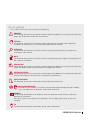
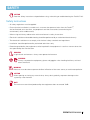
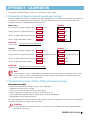
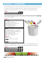
FERTIKIT 3G
™
USER MANUAL
V 001.08 - MAY 2015
© COPYRIGHT 2013, NETAFIM™
NO PARTS OF THIS PUBLICATION MAY BE REPRODUCED, STORED IN AN AUTOMATED DATA FILE OR MADE PUBLIC IN
ANY FORM OR BY ANY MEANS, WHETHER ELECTRONIC, MECHANICAL, BY PHOTOCOPYING, RECORDING OR IN ANY
OTHER MANNER WITHOUT PRIOR WRITTEN PERMISSION OF THE PUBLISHER.
ALTHOUGH NETAFIM™ TAKES THE GREATEST POSSIBLE CARE IN DESIGNING AND PRODUCING BOTH ITS PRODUCTS
AND THE ASSOCIATED DOCUMENTATION, THEY MAY STILL INCLUDE FAULTS.
NETAFIM™ WILL NOT ACCEPT RESPONSIBILITY FOR DAMAGE RESULTING FROM USE OF NETAFIM'S PRODUCTS OR
USE OF THIS MANUAL.
NETAFIM™ RESERVES THE RIGHT TO MAKE CHANGES AND IMPROVEMENTS TO ITS PRODUCTS AND/OR THE
ASSOCIATED DOCUMENTATION WITHOUT PRIOR NOTICE.
FOREIGN LANGUAGES
In the event that you are reading this manual in a language other than the English language, you
acknowledge and agree that the English language version shall prevail in case of inconsistency or
contradiction in interpretation or translation.
2 FERTIKIT USER MANUAL
Use of symbols
The symbols used in this manual refer to the following:
WARNING
The following text contains instructions aimed at preventing bodily injury or direct damage to the
crops, the FertiKit™ 3G and/or the infrastructure.
CAUTION
The following text contains instructions aimed at preventing unwanted system operation,
installation or conditions that, if not followed, might void the warranty.
ATTENTION
The following text contains instructions aimed at enhancing the efficiency of usage of the
instructions in the manual.
NOTE
The following text contains instructions aimed at emphasizing certain aspect of the operation of
the system or installation.
ACID HAZARD
The following text contains instructions aimed at preventing bodily injury or direct damage to the
crops, the product and/or the infrastructure in the presence of acid.
ELECTRICAL HAZARD
The following text contains instructions aimed at preventing bodily injury or direct damage to the
FertiKit™ 3G and/or the infrastructure in the presence of electricity.
SAFETY FOOTWEAR
The following text contains instructions aimed at preventing foot injury.
PROTECTIVE EQUIPMENT
The following text contains instructions aimed at preventing damage to health or bodily
injury in the presence of fertilizers, acid or other chemicals.
EXAMPLE
The following text provides an example to clarify the operation of the settings, method of
operation or installation.
The values used in the examples are hypothetical. Do not apply these values to your own
situation.
TIP
The following text provides clarification, tips or useful information.
FERTIKIT USER MANUAL 3
CONTENTS
Safety
Safety instructions
When using acid/chemicals
5
6
Description
Introduction
Advantages
Basic functions
Operating principle
Modularity
Compatibility
Service
Maintenance
Typical installation overview
The 7 modes
PL modes (PL/PS/PR/RL)
PB mode
SP mode
MS mode (MS/RS)
IL mode
ST mode
PD mode
7
7
7
8
8
8
8
8
9
9
10
11
12
13
14
15
16
Operation and maintenance
Operation
Maintenance
Winterization
17
18
19
Troublehooting
Symptoms regarding more than one single dosing channel
Symptoms regarding a single dosing channel
Symptoms while idle
Switchboard warning
Warranty
20
21
22
23
24
Appendices
Appendix 1 - Calibration:
1. Calculation of dosing channels opening percentage
2. Simulation with a 10 liter (2 US gal) bucket of water
3. Calibration of the FertiKitTM while irrigating
4 FERTIKIT USER MANUAL
25
25
27
SAFETY
CAUTION
Read the Safety instructions chapter before using, maintaining or troubleshooting the FertiKit™ 3G.
Safety instructions
• All safety regulations must be applied.
• Ensure that the installation is carried out in a manner that prevents leaks from the FertiKitTM,
the fertilizer/acid tanks and lines, the peripherals and the accessories (contaminating the
environment, soil or ambient area).
• When using acid always observe the acid manufacturer's safety instructions.
• Electrical installation and troubleshooting should be performed by an authorized electrician only.
• The electrical installation must comply with the local safety standards and regulations.
• Installation should be performed by authorized technicians only.
• Protection provided by the equipment can be impaired if the equipment is used in a manner other than
that specified by the manufacturer.
WARNING
In agricultural environment - always wear protective footwear.
WARNING
Always use protective equipment, gloves and goggles when handling fertilizers, acid and
other chemicals!
WARNING
Measures must be taken to prevent fertilizer infiltration of the water source, to avoid water pollution.
CAUTION
When opening or closing any manual valve, always do it gradually, to prevent damage to the
system by water hammer.
NOTE
The maximum sound level produced by the equipment does not exceed 70dB.
FERTIKIT USER MANUAL 5
SAFETY
When using acid/chemicals
ACID HAZARD
When using acid - always observe the acid manufacturer's safety instructions.
WARNING
Always use protective equipment, gloves and goggles when handling fertilizers, acid and
other chemicals!
CAUTION
There are fertilizer combinations that at high concentration might induce crystallization in the FertiKit's
lower manifold and cause clogging of the pipes.
Fertilizer combinations prone to induce crystallization:
• Calcium Nitrate + Ammonium Sulfate => Calcium Sulfate
• Calcium Nitrate + Potassium Sulfate => Calcium Sulfate
• MKP + Calcium Nitrate => Calcium Phosphate
• MAP + Calcium Nitrate => Calcium Phosphate
• Phosphoric acid + Calcium Nitrate => Calcium Phosphate
When injecting these fertilizer combinations:
• Make sure to dilute each fertilizers to the allowed concentration in the fertilizer tank prior to
injection through the FertiKit™.
• Imediately after each injection of any of the fertilizer combination above, flush the FertiKit™ with
clean water for at least 2 minutes.
In case of doubt regarding the use of any combination of fertilizers, contact your Netafim™ local
representative.
Nitric
(HNO3)
Phosphoric
(H 3PO4)
Sulfuric
(H2SO4)
Hydrochloric
(HCl)
Hydrogen
peroxide
(H2O2)
Chlorine (as
hypochloride)
Type of dosing channel
For diluted acid
For concentrated acid
Diaphragm
and O-rings
ATTENTION
When dosing acid, use a dosing channel fitted with the appropriate components according to
the type and concentration of the acid used*:
For pH correction
For maintenance of drippers
EPDM
Viton
<3%
<40%
<85%
<85%
<30%
<90%
<10%
<33%
<30%
<50%
<1%
<10%
% is by weight at 21oC (70oF)
*The table indicates the resistance of the dosing channel components to acid,
and is not a recommendation to use the acids mentioned.
WARNING
Exceeding the recommended acid concentrations will damage the dosing channels.
WARNING
Substances such as chemicals for pest/disease control might be corrosive and damage the
FertiKit™ 3G. When using any substance other than fertilizers or acids not exceeding the
concentrations in the table above, always observe the manufacturer's instructions for corrosivity.
In case of any doubt, contact your Netafim™ local representative.
6 FERTIKIT USER MANUAL
DESCRIPTION
Introduction
The FertiKitTM 3G is a fully configurable fertilizer/acid dosing unit - a highly cost-effective solution for
precise Nutrigation .
Based on a standard platform, the FertiKitTM offers 7 different operation modes, selectable according
to the site conditions, in order to maximize usage of available water flow rate and pressure on the main
irrigation line, ensuring the highest efficiency with minimum investment.
The FertiKitTM can accommodate a variety of dosing channels, dosing boosters, controllers, peripherals and
accessories to meet a vast range of applications and infrastructure constraints.
TM
Capacity range
The FertiKitTM ensures a satisfactory mixture in an extremely vast range of flow capacities.
It will accommodate a 0.1 Ha (0.25 Acres) nursery or a 400 Ha (1000 Acres) sugar cane plantation.
Main line pressure range: up to 8.5 bars (123.0 PSI).
Main line flow rate range: from 1.0 to 700.0 m3/h (from 4.4 to 3000.0 GPM).
Advantages
• A modular Nutrigation system for soil or substrate applications with minimum investment
• Efficient usage of water, fertilizers and energy
• Unrivaled range of irrigation water capacities
• Designed for any application where quantitative or proportional Nutrigation is required
• Highly profitable price/performance ratio
• Venturi operating principle - no moving parts
• Fits easily into any existing irrigation system
• Precise Nutrigation based on high-accuracy dosing channels
• Quick action dosing valves
• Available with up to 6 fertilizer/acid dosing channels
• Nutrigation recipes can be changed quickly and efficiently
• Can be operated manually or fully computerized
• NMC and other controllers can be assembled on the FertiKitTM for advanced Nutrigation control
• A wide variety of accessories and peripherals can be integrated into the FertiKitTM to enhance its functions
• High-quality components and PVC pipe work
• Aluminum, corrosion-resistant frame with adjustable legs
• Easy to install and to maintain
• Made by Netafim™
TM
TM
TM
TM
TM
Basic functions
The FertiKitTM supports the following Nutrigation functions:
• Fully controlled dosing and mixing of fertilizers/acid with source water into a homogenous nutrient
solution.
• EC/pH correction of the nutrient solution.
• Water pre-treatment
TM
FERTIKIT USER MANUAL 7
DESCRIPTION
Operating principle
The FertiKitTM doses the various fertilizers and acid into a homogeneous solution and injects it into the
irrigation water main line. The suction of the fertilizers and acid in the dosing channels is based on the
Venturi principle. This requires a pressure differentiation - available on the main line or supplied by the main
line pump or the FertiKit's dosing booster.
Modularity
The modular FertiKitTM 3G concept is based upon an array of interchangeable components that enables
rapid assembly of a wide range of configurations.
Each FertiKitTM is delivered according to the precise customer’s order, either fully factory assembled or
assembled by the local dealer.
The dealer stocks the assortment of the FertiKitTM interchangeable components.
This concept enables the dealer to assemble any specific FertiKitTM according to the customer’s order,
saving
the need to stock a large quantity of fully assembled FertiKitTM units of various common configurations.
The modular FertiKitTM 3G concept ensures prompt delivery schedules without delays!
Stock selection option
Enables the dosing of multiple fertilizers through a single dosing channel (in cases where simultaneous
dosing is not required). Suits all modes of FertiKitTM. Available in a wide variety of configurations, from a
single dosing channel with 2 fertilizers to as many dosing channels and fertilizers as required. For further
information, contact Netafim™.
Compatibility
The FertiKitTM 3G can be incorporated in an existing or a planned project; in either case it offers a highly
cost-effective solution for NutrigationTM by taking maximum advantage of the infrastructure conditions.
Any available pressure surplus can be used for the FertiKit’s operation. In order to configure the most
cost-effective FertiKitTM , making the maximum use of available pressure.
ATTENTION
Calculations are either in metric or in US units - consistency in the type of units used is essential.
Service
Servicing the FertiKitTM 3G is a prompt and simple process. The dealer keeps a small quantity of
interchangeable components on hand, for replacement on site within a few minutes.
Maintenance
To prevent failures and extend the life cycle of the FertiKitTM, regular maintenance must be carried out
by the user, such as periodic rinsing of filters and calibration of the EC/pH sensors. For full maintenance
instructions, see Maintenance (page 18).
8 FERTIKIT USER MANUAL
DESCRIPTION
Typical installation overview
The drawing below represents the typical infrastructure suitable for the PL mode. Each one of the FertiKit™
3G 7 modes fits a different infrastructure configuration. (see the schematic diagrams in Modes, pages 10-16).
FertiKit 3G
TM
14
13
15
20
16
17
19
21
22
16
18
Main parts of the FertiKit™ and its infrastructure
The list below presents the Main parts of the FertiKit™ and the parts of the infrastructure required for the
operation of the FertiKit™ various modes (see pages 10-16).
1 Dosing channel + Venturi
12 Pressure switch
2 Upper manifold pressure gauge
13 Fertilizer/acid stock tank
3 Lower manifold presure gauge
14 Manual valve (fertilizer)
4 Sampling outlet
15 Fertilizer/acid filter
5 Controller
16 Manual valve (isolation)
6 EC sensor
17 Main line
pressure sustaining valve (PSV)
7 pH sensor
8 EC/pH transducer
9 Dosing booster
10 Dosing booster switchbox
11 Check valve
Color code:
22 Main line
pressure reducing valve (PRV)
23 Sampling outlet
24 Saddle fitting
25 Command tube
26 Pressure sustaining valve (PSV)
27 Pressure reducing valve (PRV)
18 Irrigation valve
28 Water meter
19 Water meter
29 Air release valve
20 Main line filter
21 Main line pump
Supplied (part of the FertiKit™),
Not supplied (part of infrastructure),
Optional.
The 7 modes
Each one of the FertiKit™ 3G 7 modes depicted on the folowing pages fits a specific infrastructure configuration.
FERTIKIT USER MANUAL 9
DESCRIPTION
PL modes (PL/PS/PR/RL)
Operating principle: The pressure differential required to
generate fertilizer suction via the Venturis is produced by a
booster pump integrated in the FertiKitTM.
These modes of operation, where the lower manifold is under
low pressure (around 0 bars/PSI), permits the use of high-efficiency
Venturis with high suction capacity and low motive flow consumption.
Flow rate: 20 - 700 m³/h (85 - 3000 GPM)
Suitable for main line pressure:
PL: 2.5 - 6.5 bars (36 - 94 PSI).
PR with PRV 27 : 6.5 - 8.5 bars (94 - 123 PSI)
PS with PSV 26 : Based on cavitation risk.
RL with PRV 27 and PSV 26 : 2.5 - 8.5 bars (36 - 123 PSI)
Dosing channels:
Accommodates a wide variety of dosing channels for fertilizer
and concentrated/diluted acid:
• Up to 6 x 50 - 1000 l/h (13 - 265 GPH)
• Optional - Concentrated acid channel, 50 l/h (13 GPH).
Total fertilizer/acid suction capacity - up to 6000 l/h (1585 GPH).
Controller: NMC-Pro, NMC-XL, NMC-Junior, (Other controllers or manual system without controller - optional).
EC/pH: Single, monitoring and control.
Schematic diagram
18
21
20
22
19
16
16
11
2
12
26
4
6
9
27
1
7
17
5
8
10
3
Dosing channel
Scope of delivery
Direction of flow
10 FERTIKIT USER MANUAL
15
14
13
See legend on page 9
DESCRIPTION
PB mode
Operating principle: The pressure differential required
to generate fertilizer suction via the Venturis is produced
by a booster pump integrated in the FertiKitTM.
This mode of operation, where the smaller system pump
is installed upstream from the Venturis, permits the use of a small
booster pump, reducing the investment required and saving energy.
This mode is suitable for relatively low flow rates and pressures.
Flow rate: 5 - 70 m³/h (22 - 300 GPM)
Suitable for main line pressure: 1.5 - 2.5 bars (22 - 36 PSI)
Additional conditions:
The pressure supplied by the dosing booster is added to the main line
pressure. Their sum (in the upper manifold) should not exceed
6.5 bars (94 PSI)
Dosing channels:
Accommodates a wide variety of dosing channels for fertilizer
and concentrated/diluted acid:
• Up to 4 x 50 - 370 l/h (13 - 100 GPH) • Optional - Concentrated acid channel, 50 l/h (13 GPH).
Total fertilizer/acid suction capacity - up to 1480 l/h (390 GPH).
Controller: NMC-Pro, NMC-XL, NMC-Junior, (Other controllers or manual system without controller - optional).
EC/pH: Single, monitoring and control.
Schematic diagram
21
20
18
22
19
16
16
12
17
5
6
7
2
9
8
11
4
1
10
3
Dosing channel
Scope of delivery
Direction of flow
15
14
13
See legend on page 9
FERTIKIT USER MANUAL 11
DESCRIPTION
SP mode
Operating principle: The pressure differential required
to generate fertilizer suction via the Venturis is produced
by a booster pump integrated in the FertiKitTM.
This mode of operation, where the system pump
is installed upstream from the Venturis, permits the use of a smaller
booster pump, reducing the investment required and saving energy.
This mode is suitable for relatively low flow rates and pressures.
For applications that use very high concentration fertilizers and acid.
The solution has to be mixed in the main line.
SP mode is not equipped with a lower manifold.
(Can be supplied to the USA market with all parts inch-based to
facilitate replacement using locally available spare parts).
Flow rate: 5 - 250 m³/h (22 - 1100 GPM)
Suitable for main line pressure: 1.5 - 3.5 bars (22 – 51 PSI)
Dosing channels:
Accommodates a wide variety of dosing channels for fertilizer and concentrated/diluted acid:
• Up to 4 x 50 - 370 l/h (13 - 100 GPH) • Optional - Concentrated acid channel, 50 l/h (13 GPH).
Total fertilizer/acid suction capacity - up to 1480 l/h (400 GPH).
Controller: NMC-Pro, NMC-XL, NMC-Junior, (Other controllers or manual system without controller - optional).
EC/pH: Single, monitoring and control.
Schematic diagram
21
20
22
18
19
16
16
17
12
6
7
2
5
9
11
4
1
Dosing channel
Scope of delivery
Direction of flow
12 FERTIKIT USER MANUAL
15
14
8
10
13
See legend on page 9
DESCRIPTION
MS mode (MS/RS)
Operating principle: For systems operating under negative suction from a reservoir or a tank [max. height: 6 meters (20 feet)]
Utilizes the main line pump pressure.
Saves the need for a dosing booster.
Flow rate: 20 - 700 m³/h (85 - 3000 GPM)
Suitable for main line pressure:
Upstream from the pump: -0.3 - +0.6 bar (-4 - +9 PSI)
At the outlet of the pump: 2.5 - 6.5 bars (36 - 94 PSI)
RS with PRV 27 :
6.5 - 8.5 bars (94 - 123 PSI) at the FertiKitTM inlet.
Additional conditions:
Requires the connection of the FertiKit's outlet to the main line
upstream from the pump.
The main line pump should be able to deliver the flow rate required for the
operation of the FertiKitTM + the field consumption.
Dosing channels:
Accommodates a wide variety of dosing channels for fertilizer and concentrated/diluted acid:
• Up to 6 x 50 - 1000 l/h (13 - 265 GPH) • Optional - Concentrated acid channel, 50 l/h (13 GPH).
Total fertilizer/acid suction capacity - up to 6000 l/h (1585 GPH).
Controller: NMC-Pro, NMC-XL, NMC-Junior, (Other controllers or manual system without controller - optional).
EC/pH: Single, monitoring and control.
Schematic diagram
18
21
P -0.3 - +0.6 bar
20
(-4 - +9 PSI)
P 2.5 - 6.5 bar
19
(36 - 94 PSI)
16
17
16
2
5
27
4
6
1
7
8
3
Dosing channel
Scope of delivery
Direction of flow
15
14
13
See legend on page 9
FERTIKIT USER MANUAL 13
DESCRIPTION
IL mode
Operating principle: The pressure differential required to
generate fertilizer suction via the Venturis is produced by a
booster pump integrated in the FertiKitTM.
In this mode of operation, the lower manifold is at low
pressure (around 0 bar/psi) this allows the use of high-efficiency
Venturis with high suction capacity and low motive flow consumption.
Since all the main line water flows through the system, slight
pressure losses at the FettiKit™ outlet should be considered
(see the table below).
Flow rate: 3 - 18 m³/h (13 - 85 GPM)
Suitable for main line pressure: 2.5 - 5.5 bars (36 - 79 PSI)
Dosing channels:
Accommodates a wide variety of dosing channels for fertilizer and
concentrated/diluted acid:
• Up to 6 x 50 - 600 l/h (13 - 156 GPH)
• Optional - Concentrated acid channel, 50 l/h (13 GPH).
Total fertilizer/acid suction capacity - up to 3600 l/h (950 GPH).
Pressure losses
Flow rate
m³/h (GPM)
5 (22)
10 (44)
15 (66)
Controller: NMC-Pro, NMC-XL, NMC-Junior,
(Other controllers or manual system without controller - optional).
EC/pH: Single, monitoring and control.
Pressure losse
bar (PSI)
0.1 (1.45)
0.3 (4.35)
0.6 (9.55)
Schematic diagram
18
21
28
27
20
11
5
2
9
29
12
4
6
1
7
8
10
3
Dosing channel
Scope of delivery
Direction of flow
14 FERTIKIT USER MANUAL
15
14
13
See legend on page 9
DESCRIPTION
ST mode
Operating principle: For systems operating at low pressure from an on-ground reservoir or a tank
[max. height: 6 meters (20 feet)]
The dosing booster pump also serves as main line pump.
Supplied with a manual or a semi-automatic filter.
Flow rate: 1 - 16 m³/h (4.4 - 70 GPM)
Suitable for main line pressure:
Upstream from the pump: -0.3 - +0.6 bar (-4 - +9 PSI)
At the outlet of the pump: 2.0 - 5.5 bars (29 - 80 PSI)
Additional conditions:
The selection of the dosing booster considers the required
field flow + the TC.
Dosing channels:
Accommodates a wide variety of dosing channels for fertilizer
and concentrated/diluted acid:
• Up to 6 x 50 - 600 l/h (13 - 156 GPH) • Optional - Concentrated acid channel, 50 l/h (13 GPH).
Total fertilizer/acid suction capacity - up to 3600 l/h (950 GPH).
Controller: NMC-Pro, NMC-XL, NMC-Junior, (Other controllers or manual system without controller - optional).
EC/pH: Single, monitoring and control.
Schematic diagram
18
P -0.3 - +0.6 bar
(-4 - +9 PSI)
16
11
9
19
5
2
20
29
12
4
6
1
7
17
8
10
3
Dosing channel
Scope of delivery
Direction of flow
15
14
13
See legend on page 9
FERTIKIT USER MANUAL 15
DESCRIPTION
PD mode
Operating principle: Utilizes the main line pressure
or gravity feed.
Saves the need for a dosing booster.
Also suitable for applications where there is no
electricity on the site (contact Netafim™).
Flow rate: 10 - 200 m³/h (44 - 880 GPM)
Suitable for main line pressure: 4.5 - 8.0 Bars (65 - 116 PSI)
Additional conditions:
For the dosing channels to provide proper suction, the pressure
downstream from the PRV should be at least 50% of the the pressure upstream
from the PRV (The eficiency of the Venturis decreases if this condition is not met).
In addition the system must supply suficient pressure for the field demand.
Dosing channels:
Accommodates a wide variety of dosing channels for fertilizer and concentrated/diluted acid:
• Up to 4* x 50 - 370 l/h (13 - 100 GPH) • Optional - Concentrated acid channel, 50 l/h (13 GPH).
Total fertilizer/acid suction capacity - up to 1480 l/h (390 GPH).
*If EC/pH is installed it occupies the location of one dosing channel (power required).
Controller: NMC-Pro, NMC-XL, NMC-Junior, NMC DC
(Other controllers or manual system without controller - optional).
EC/pH: None (Single monitoring only - optional)
Schematic diagram
18
20
19
23
16
22
16
25
2
7
24
6
5
1
8
3
Dosing channel
Scope of delivery
Direction of flow
16 FERTIKIT USER MANUAL
15
14
13
See legend on page 9
OPERATION AND MAINTENANCE
Operation
The routine operation of the FertiKitTM is almost totally automatic, controlled by the controller
(for the operation of the controller, see the Controller Manual).
All you need is to make sure that:
• Electricity is supplied to the FertiKitTM.
• Adequate quality water at the appropriate flow rate and pressure is supplied at the inlet of the FertiKitTM
(see FertiKitTM Hydraulic Conditions Checklist).
• Properly dissolved fertilizers, according to the agronomist's instructions, are constantly present in the
stock tanks.
• If acid is used - it is constantly present in the acid stock tank and does not exceed the recommended
concentration (see ATTENTION, page 6).
Dual dosing channel
If more than 4 dosing channels are required (up to 6), the dual dosing channel option is used.
• Up to 2 dual dosing channels are installed on the FertiKitTM 3G, at the 1 and 4 manifold positions.
• The dual dosing channel option is applicable with 50-600 l/h (13-158 GPH) and 1000 l/h (265 GPH) Venturis only.
Dual dosing channel schematic diagram
1
2
3
4
LEGEND
Scope of the
dual dosing channel
Direction of flow
CAUTION
Only compatible products can be injected through the dual dosing channel.
There are fertilizer combinations that should never be used in the dual dosing
channel as they will induce crystallization and cause clogging of the pipes.
Fertilizer combinations prone to induce crystallization:
• Calcium Nitrate + Ammonium Sulfate => Calcium Sulfate
• Calcium Nitrate + Potassium Sulfate => Calcium Sulfate
• MKP + Calcium Nitrate => Calcium Phosphate
• MAP + Calcium Nitrate => Calcium Phosphate
• Phosphoric acid + Calcium Nitrate => Calcium Phosphate
In case of doubt regarding the use of any combination of fertilizers in the
dual dosing channel, contact your Netafim™ local representative.
FERTIKIT USER MANUAL 17
OPERATION AND MAINTENANCE
Maintenance
CAUTION
When opening or closing any manual valve, always do it gradually, to prevent damage to the
system by water hammer.
To prevent failures and extend the life cycle of the FertiKitTM, the user must carry out regular maintenance.
• Keep the FertiKitTM dosing unit and its immediate environment clean and dry.
CAUTION
Before calibrating the EC and pH sensors, gradually close the isolation valves and open the
sampling valve until the pressure in the system is released.
• The FertiKitTM dosing unit and the supply water and irrigation system must be inspected regularly.
Regular inspection
Description
Rinsing of fertilizer filters*
Rinsing of supply water filters*
Water and fertilizer leak inspection
Calibration of the pH sensor
Calibration of the EC sensor
How often
Once a day
Once a day
Once a week
Every 2-4 weeks
Every 4 weeks
Instructions
Visual inspection
See the EC/pH Transducer Manual
* Manual filters only.
Check the FertiKit ™ hydraulic conditions every 4 weeks
Consult the main line flow meter and pressure gauge, the upper manifold and lower
manifold pressure gauges and the Rotameters of the dosing channels, fill in the data on
the FertiKitTM Hydraulic Conditions Checklist provided by the installer and make sure that
all the hydraulic conditions match the reference data.
When verifying the flow rate for each dosing channel,
make sure the cursors on all the Rotameters are adjusted.
NOTE
The Rotameter's sacle is calibrated by the manufacturer for measurement of the
flow rate of water (H2O). Certain inacuracies may be observed when the flow rate
of liquids with different densities, such as fertilizers and acids, is measured.
ATTENTION
Once a month, read the measured flow rates of the dosing channels
and compare them with the flow rates defined in the controller,
to check whether any changes have occurred.
18 FERTIKIT USER MANUAL
OPERATION AND MAINTENANCE
Winterization
CAUTION
When opening or closing any manual valve, always do it gradually, to prevent damage to the
system by water hammer.
In areas susceptible to freezing temperatures, if the system is not required for irrigation during the winter
(mainly in open field applications) perform the following procedure to avoid damage caused by freezing
when the FertiKitTM is idle for the winter period:
At the beginning of winter:
• Gradually close the isolation valves and open the sampling valve until the pressure in the system is
released.
• Remove EC and pH sensors and store the pH sensor immersed in KCL solution (supplied with the sensor)
or in calibration buffer 4 at temperature 18-25˚C (64-77˚F). The pH sensor must never be dry
(see EC/pH Transducer Manual).
• Empty the FertiKitTM of water.
At the end of winter:
• Reinstall the EC and pH sensors and calibrate them (see EC/pH Transducer Manual).
• Gradually open the isolation valves until the pressure in the system is restored.
FERTIKIT USER MANUAL 19
TROUBLESHOOTING
This chapter is a systematic guide to the actions to be taken in the case of a malfunction of the FertiKitTM.
ATTENTION
Before proceeding to troubleshoot any malfunction, make sure that:
• The controller settings regarding the dosing channels are correct and match the dosing channels
of the FertiKitTM (see the Controller Manual).
• The controller settings regarding the field valves are correct (see the Controller Manual).
Perform the actions in their order of appearance until the malfunction is fixed.
If you identify faulty parts - consult your Netafim™ representative.
CAUTION
Only qualified electricians are permitted to perform electrical installations and repairs!
CAUTION
If isolation valves have been installed on the system, ensure that they are in closed position before
troubleshooting any hydraulic malfunction.
ATTENTION
If fertilizers from a different manufacturer have been recently in use and changes in EC and pH are
recorded, perform calibration of the system before assuming a malfunction of the FertiKitTM
(see Appendix 1 - Calibration, page 25).
Symptoms regarding more than one single dosing channel
If one or more of the following symptoms occur regarding more than one single dosing channel,
perform the actions listed bellow:
Controller warnings
• Low EC
• High pH
• Low fertilizer/acid flow rate
Rotameter reading
• Low fertilizer/acid flow rate
Action
1)
For controller warnings only - check and calibrate the EC and pH sensors
(see the EC/pH Transducer Manual).
2) Have a qualified electrician check that electricity is being supplied to the FertiKitTM and that all the
electrical components are properly connected (see the Switchboard Manual).
3) Check that the hydraulic conditions comply with the reference data in the
FertiKitTM Hydraulic Conditions Checklist.
If NO, restore the original hydraulic conditions according to the reference data in the
FertiKitTM Hydraulic Conditions Checklist.
If YES or if the malfunction is still not fixed after restoring the original hydraulic conditions,
in PL or PB mode - have a qualified electrician check the dosing booster:
Does it function? Does it rotate in the correct direction?
If not - the electrician should swap between phases L1 and L3 (see the Dosing Booster Manual).
20 FERTIKIT USER MANUAL
TROUBLESHOOTING
4)
Check for an air pocket in the dosing booster impeller chamber (see the Dosing Booster Manual):
Open the FertiKitTM sampling valve until a stable flow, free of air-bubbles, is obtained.
5) If the original hydraulic conditions are still not restored - loosen the dosing booster's bleeding screw
and wait until a stable flow, free of air-bubbles, is obtained, then retighten the bleeding screw
(see the Dosing Booster Manual).
6) Check the dosing booster's impeller chamber for clogging:
If it is clogged - it should be dismantled and thoroughly cleaned (see the Dosing Booster Manual).
If after implementing all the above steps the malfunction is still not fixed -consult your NetafimTM representative.
Symptoms regarding a single dosing channel
H
If one or more of the following symptoms occur regarding a
single dosing channel, perform the actions listed bellow:
G
F
Controller warnings
• Low EC
• High pH
• Low fertilizer/acid flow rate
E
Rotameter reading
• Low fertilizer/acid flow rate
A
B
C
D
Action
1)
Check that there is fertilizer/acid solution in the stock tank A .
2) Check that the stock tank manual valve B is in the OPEN position.
3) Check that the fertilizer/acid filter C is clean - If not, it should be dismantled and thoroughly cleaned.
FERTIKIT USER MANUAL 21
TROUBLESHOOTING
4)
Check the fertilizer/acid line D (from the stock tank to the dosing channel) for leaks and breaches
and make sure all the connectors are tightened.
5) Make sure the dosing channel's needle valve E is open according to the reference data in the
FertiKitTM Hydraulic Conditions Checklist.
6) Visually check the needle valve E for chemical damage (internal deformation).
If internal deformation is present - replace the needle valve.
7)
Visually check the needle valve E for clogging.
If clogging is present - thoroughly clean the needle valve.
8) Check that the dosing valve F is functioning:
With the controller in MANUAL mode, set the dosing valve F to ON (see the Controller Manual).
The LED on the dosing valve should be lit.
If it is not - have a qualified electrician check the dosing valve's cable for electrical continuity.
If the cable is in working order - check the controller (see the Controller Manual).
If the controller and the cable are in working order - toggle the dosing valve F to OFF and again to ON
in the controller (see the Controller Manual). A "Click" should be heard from the dosing valve with
each toggle - If a "Click" is not heard, replace the dosing valve (consult your Netafim™ representative).
If a "Click" is heard and the dosing valve F still does not open - disconnect the dosing valve from the
dosing channel and with the dosing valve set to ON in the controller (see the Controller Manual),
check for clogging by injecting water at low pressure through the dosing valve.
If there is clogging - thoroughly clean the dosing valve F with running water.
If there is no clogging and the dosing valve F still does not open - replace it
(consult your Netafim™ representative).
9) Visually check the non-return valve G for any internal deformation or damage to its flat ring gasket.
If present - replace the non-return valve (consult your Netafim™ representative).
10) Check the non-return valve G for clogging by injecting water at low pressure through it
(make sure to respect the direction of flow).
If there is clogging - thoroughly clean the non-return valve G with running water.
11) Disconnect the Venturi H from the manifolds and from the dosing channel and check it for clogging,
visually and by injecting water at low pressure through it.
If there is clogging - thoroughly clean the Venturi H with running water.
12) Visually check the Venturi H for chemical damage (internal deformation).
If internal deformation is present - replace the Venturi (consult your Netafim™ representative).
If after implementing all the above steps the malfunction is still not fixed - consult your Netafim™ representative.
Symptoms while idle
If the following symptoms occur while the FertiKitTM is idle, perform the actions listed bellow:
Controller warnings
• High EC
• Low pH
• While idle - Uncontrolled fertilizer/acid flow rate or a fertilizer/acid leak or breach
22 FERTIKIT USER MANUAL
TROUBLESHOOTING
Action
NOTE
When using a dosing valve with manual override (model: Fip S12 or S22),
make sure the dosing valve selector is in the CLOSED position.
OPEN
Check if the dosing valves leak when closed:
1)
CLOSE
Close all the manual valves B for fertilizers and acid.
2) Make sure the level of the solution in all the the stock tanks is higher than the
dosing valves.
3) With the controller in MANUAL mode, set all the dosing valves to OFF
(see the Controller Manual).
4)
Disconect one of the the dosing valves from the non-return valve
(downstream from the dosing valve).
5) Open the fertilizer manual valve B .
If a leak from the dosing valve is visible - disconect the dosing valve from the dosing channel.
6) With the controller in MANUAL mode, set the dosing valve to ON
(see the Controller Manual).
7)
Thoroughly clean the dosing valve with running water.
8) Repeat steps 4-7 for each fertilizer and acid dosing channel.
9) After completing the procedure, open all the manual valves B for fertilizers and acid.
10) If the malfunction is still not fixed - replace the dosing valve.
If after implementing all the above steps the malfunction is still not fixed - consult your Netafim™ representative.
Switchboard warning
If the following symptom occurs during operation, perform the actions listed bellow:
Switchboard warning light
• The switchboard warning light is on (When the dosing booster is either ON or OFF).
Action
1)
Check if the pressure on the main line is low compared with the reference data on the
FertiKitTM Hydraulic Conditions Checklist:
If YES, restore the original main line pressure.
2) Check if the overload protection breaker is ON (see the Switchboard Manual).
Toggle it OFF and ON again.
If the switchboard warning light is still on or the overload protection breaker trips (turns to OFF) again,
have a qualified electrician check if the dosing booster is in working order (see the Dosing Booster
Manual) and check if there are irregularities in the electricity voltage supplied to the FertiKitTM.
If after implementing all the above steps the malfunction is still not fixed - consult your Netafim™ representative.
FERTIKIT USER MANUAL 23
WARRANTY
Netafim™ warrants all the components of the FertiKitTM to be free of defects in material and workmanship
for 1 (one) year from the date of installation, provided the installation has been reported to Netafim™
within 30 days of installation.
If the installation was not reported or was reported later than 30 days from the date of installation,
Netafim™ will warrant the FertiKitTM for a period of 18 months from the date of production, according to its
serial number.
If a defect is discovered during the applicable warranty period, Netafim™ will repair or replace, at its
discretion, the product or the defective part.
The above does not apply to EC and pH sensors, since they are wearable. Netafim™ will warrant these
items to be free of defects in material and workmanship for 3 months from the date of installation,
provided the installation has been reported to Netafim™ within 30 days, or 6 months from date of
production if installation was not reported or was reported later than 30 days from the date of installation.
CAUTION
When not installed, the pH sensor must be immersed in KCL solution (supplied with the sensor)
or in calibration buffer 4 at temperature 18-25˚C (64-77˚F), protected from freezing and not be
exposed to pressure greater than 6 bars (87 PSI).
Damage due to these causes is not covered by warranty.
This warranty does not extend to repairs, adjustments or replacements of a FertiKitTM or part that results
from misuse, negligence, alteration, force majeure, lightning, power surge, improper installation or
improper maintenance.
If a defect arises in your Netafim™ product during the warranty period, contact your Netafim™ supplier.
Limited warranty
This warranty is subject to the conditions in Netafim's official warranty statement.
(For the full text of Netafim's official warranty statement, please contact Netafim™).
24 FERTIKIT USER MANUAL
APPENDIX 1 - CALIBRATION
The process of calibrating the FertiKitTM is carried out in three stages:
1. Calculation of dosing channels opening percentage
To finely calibrate the FertiKitTM in order to achieve homogeneous and stable dosing, perform the following
calculation for each dosing channel (fertilizers and acid) to determine the amount of suction reduction
needed to attain the required fertilizer/acid flow rate.
Metric units
EXAMPLE
Flow rate of the largest irrigation shift
m3 /hr
X
Dosing ratio of a single fertilizer/acid
l/m3
=
Result: a single fertilizer/acid flow rate
l/hr
X 1.25 =
Result: target Rotameter reading
l/hr
120
X
3
=
360
X 1.25 =
450
m3 /hr
l/m3
l/hr
l/hr
DEFINITION
The quantity of fertilizer/acid (l)
Dosing ratio =
1 m3 irrigation water
US units
EXAMPLE
Flow rate of the largest irrigation shift
GPM
X
Dosing ratio of a single fertilizer/acid
US gal/1000 US gal
X 0.06 =
Result: a single fertilizer/acid flow rate
GPH
X 1.25 =
Result: target Rotameter reading
GPH
500
X
15
X 0.06 =
45
X 1.25 =
56
GPM
US gal/1000 US gal
GPH
GPH
DEFINITION
The quantity of fertilizer/acid (US gal)
Dosing ratio =
1 THG (1000 US gal) irrigation water
NOTE
The Rotameter's sacle is calibrated by the manufacturer for measurement of the flow rate of water
(H2O). Certain inacuracies may be observed when the flow rate of liquids with different densities,
such as fertilizers and acids, is measured.
2. Simulation test with a 10 liter (2 US gal) bucket of water
Instruments needed
• Good-quality portable EC and pH sensors, finely calibrated
• Calibration solutions for EC and pH
• Bucket with a scale for up to 10 liters (2 US gallons)
• Measuring tube or syringe with a scale for up to 100 cc (1 oz)
• Clean (preferably distilled) water for cleaning sensors during calibration
• Blotting paper for cleaning and drying
The client prepares the fertilizer solutions and the acid solution (if required) in the stock tanks according to
the recipe advised by the agronomist/consultant.
ATTENTION
Ensure the fertilizers and acid solutions in the stock tanks have been thoroughly agitated before
starting the simulation.
FERTIKIT USER MANUAL 25
APPENDIX 1 - CALIBRATION
Note the required dosing ratio of each fertilizer solution and the dosing ratio of the acid solution (if used).
Fill a bucket with 10 liters (2 US gallons) of the client's supply water (without fertilizer or acid).
Measure the EC and the pH levels of the water in the bucket using calibrated portable sensors.
EXAMPLE
Supply water (without fertilizer or acid)
EC
0.3
pH
7.8
Using a measuring tube or a syringe, take a dose from each fertilizer solution and from the acid solution (if
used) according to the proportions determined by the dosing ratio (see example below) and mix thoroughly
with the water in the bucket.
EXAMPLE
A
Metric units
For a fertilizers dosing ratio of 5 l/m3 each
and an acid dosing ratio of 2 l/m3
the quantities for 10 liters of water in the
Bucket-simulation-test will be
50 cc of each fertilizer solution and
20 cc of the acid solution
B
C
Acid
10 liters
(2 US gal)
US units
For a fertilizers dosing ratio of 1.5 US gal/THG each
and an acid dosing ratio of 1.1 US gal/THG
the quantities for 2 US gallons of water in the
Bucket-simulation-test will be
0.38 oz* of each fertilizer solution and
0.28 oz** of the acid solution
DEFINITIONS
1 US gal = 128 oz
* 1.5 X 2
= 0.003 US gal = 0.384 oz
1000
** 1.1 X 2
= 0.0022 US gal = 0.28 oz
1000
Measure the EC and the pH levels of the mixture in the bucket using calibrated portable sensors.
Compare the measured EC and pH values to the target values set by the agronomist/consultant.
EXAMPLE
After adding the fertilizers and acid
Target values
Deviation from target value
In range
GOOD!
Out of range
-30%
26 FERTIKIT USER MANUAL
EC pH
1.6 5.5
1.8 5.8
11% 5%
Target value
Out of range
+30%
APPENDIX 1 - CALIBRATION
With the controller set to operate according to EC/pH values - if the EC and pH values measured in the bucket
are within a range of ±30% deviation from the target values, the system will be able to correct them
automatically.
If the values are out of the ±30% range, check the data and consult the agronomist/consultant.
3. Calibration of the FertiKit ™ while irrigating
WARNING
Extreme EC or pH values may damage the crop.
Perform the following procedure only after completing stage 2 above (Simulation test with a 10 liter
or 2 US gallon bucket of water) with satisfactory results.
NOTE
The following steps explain the operations to be performed, regardless of the type of controller
used. For the operation of your controller's interface, consult the Controller Manual.
However, since the NMC Pro controller is widely used - its interface screens for the execution of
each step are noted.
NOTE
Before the calibration, confirm that the EC and the pH sensors of the FertiKit™ have been
calibrated according to the instructions in the EC/pH Installation Manual.
Define the dosing configuration, while the EC and pH controls are in the OFF position (NMC Pro - screen 7.7).
In the EC and pH alarm definitions, set the EC and pH alarm to the OFF position (deactivated)
(NMC Pro - screen 3.6).
Enter the data for the irrigation valves, and the dosing ratio for each dosing channel
(NMC Pro - screens 1.1-1.2-1.3).
Run the program (NMC Pro - screen 2.2).
Allow a few minutes for the pipes to fill up and the flow rate to stabilize.
Reduce the suction of the dosing channels by adjusting the manual needle valve of each dosing channel
until the "target Rotameter reading" calculated in stage 1 (page 25) is attained.
NOTE
The Rotameter's sacle is calibrated by the manufacturer for measurement of the flow rate of water
(H2O). Certain inacuracies may be observed when the flow rate of liquids with different densities,
such as fertilizers and acids, is measured.
Check the appropriate controller screen for the measured EC and pH values (NMC Pro - hot screen 4).
If the desired values have been reached, check opening percentages of the dosing valves.
The EC and pH target values should be attained with the dosing valves opened to 50% - 80% of their capacity.
If the EC and pH target values are attained with the dosing valves opened less than 50%, reduce the
dosing channel suction rate, until the EC and pH target values are reached.
NOTE
Every change in the flow rate of the needle valve must be updated afterwards in the controller
(NMC Pro - screen 7.6).
FERTIKIT USER MANUAL 27
APPENDIX 1 - CALIBRATION
If the EC and pH target values cannot be attained, and the dosing valves are opened more than 85%,
measures should be taken to increase the dosing ratio - if feasible, slightly increase the concentration of
the fertilizer solution and/or reduce the water flow rate to the field during irrigation.
If not - consult the agronomist/consultant.
In a field where the flow rate changes significantly from one irrigation shift to the next, try to be at a
minimum of 50% dosing valve opening for the low flow rate shift, and a maximum of 80% for the high
flow rate shift.
When the calibration process is completed, return to the EC and pH control screen in the controller,
define the deviation in EC and pH values for the channels and switch the EC and pH control to ON
(NMC Pro - screen 7.7-7.6).
In the EC and pH alarm definitions, define the EC and pH deviation from the target values that, if attained,
will trigger the alarm and set the EC and pH alarm to the ON position (activated) (NMC Pro - screen 3.5-3.6).
NOTE
EC and pH values must not exceed a ±30% deviation from the target values.
ATTENTION
Once a month, read the measured flow rates of the dosing channels and compare them with
the flow rates defined in the controller, in order to check whether changes have occurred
(NMC Pro - screen 7.6).
After completing the calibration process, fill out the FertiKit™ Hydraulic Conditions Checklist in three
copies. Make sure to fill out all the boxes of the reference row.
28 FERTIKIT USER MANUAL
30 FERTIKIT USER MANUAL
GROW MORE WITH LESS
WWW.NETAFIM.COM
82000-015400
82000-015398
82000-015395
82000-015390
82000-015380
82000-015370