1
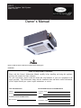
40GJ*C Cassette Ductless Split System Sizes 12 to 24 Owner' s Manual the environmentally sound refrigerant NOTE: Read the entire instruction manual before starting the installation. NOTE TO EQUIPMENT OWNER: Please read this Owner’s Information Manual carefully before installing and using this appliance and keep this manual for future reference. For your convenience, please record the model and serial numbers of your new equipment in the spaces provided. This information, along with the installation data and dealer contact information, will be helpful should your system require maintenance or service. UNIT INFORMATION DEALERSHIP CONTACT INFORMATION Model # Company Name: Serial # Address: INSTALLATION INFORMATION Phone Number: Date Installed Technician Name: 4 User Notice ƹ When operating, the entire capacity of the cooperating indoor unit should be not larger than 150% of outdoor unit. Otherwise, it will cause the shortage of cooling (heating) capacity. ƹ A Breaker(or fuse) need to be installed in every indoor unit, and the capacity should in according with indoor unit’s electrical parameter; all the indoor units are required to be centralized controlled by a total Switch, this Switch can cut off the electric power supply in case of emergency. The Breaker(or fuse) on each indoor units have the function of short circuit prevention and abnormal overload avoiding, it should be connected in normal situation. The total switch controlling the power supply of all the indoor units. Before clearing and maintenance job being carried out to the indoor units, it is very important to turn off the total power supply switch. ƹ In order to turn on the units successfully, the main power switch should be opened 8 hours before the operation. ƹ After receiving the turn off signal, every indoor unit will continue to work for 20-70sec to make use of the rest cool air or the rest heat air in the heat exchanger, while preparing for the next operation. And this is normal. ƹ When the selected operating mode of the indoor unit are clash with the operating mode of the outdoor unit, the malfunction light will blink after 5s on the indoor unit or remote controller showing that the operation clash, then the indoor unit will stop. At this time, change the operation mode of the indoor unit to the one that would not clash with the outdoor operating mode to make the operation normal. The cooling mode is not clash with the dry mode, while the fan mode is not clash with any mode. ƹ The appliance shall not be installed in the laundry. ƹ An all-pole disconnection switch having a contact separation of at least 3mm in all poles should EHFRQQHFWHGLQ¿[HGZLULQJ ƹ Information regarding transport/storage temperature (-13 -131°F/ -25~55°C ) is missing. ƹ Main switch provided by end user: main switch handle should be black or gray, it can be locked in “OFF” position with padlock. ƹ The main disconnection device should be explained in user manual and the height should be recommended at 0.6-1.7m. over current protection is required(UL 1995,CSA C22.2). ° ƹ The cooling range of the unit is the outdoor environment temp.23-118.4 F(-5~48°C) DB, the heating range of ° the unit( only for the heat pump type unit) is the outdoor environment temp. 5-80.6 F(-15~27°C) WB. This product must not be disposed together with the domestic waste. This product has to be disposed at an authorized place for recycling of electrical and electronic appliances. Contents Safety Information .................................................................................................... 1 Install of The Compact Panel Cassette Type Indoor Unit ......................................... 2 Constitutes and Names of Parts of Compact Panel Cassette Type Indoor Unit ...... 10 Working Temperature Range .................................................................................. 11 Malfunction Debarring............................................................................................ 12 Maintenance Method .............................................................................................. 14 Safety Information Safety Information Please read this manual carefully before use this unit, and operate it correctly according to the guide in this manual. Please take specially note to the meaning of these two marks: Warning!: This mark means that it may cause casualty or badly heart if the operation is incorrect. Note!: This mark means that it may cause casualty or property loss if the operation is incorrect. Warning: ƹ Do not adopt fuse with unsuitable capacity or adopt iron thread instead of fuse, otherwise malfunction RU¿UHPD\KDSSHQHG ƹ Cut down the main power switch immediately if malfunction (such as smell the burning odor etc.) happened. ƹ Maintain ventilation to prevent oxygen leakage in room. ƹ'RQ¶WLQVHUW¿QJHURUVWLFNOLNHWKLQJVLQWRGLVFKDUJHYHQWRURXWOHWJULOO ƹ Please make sure that the unit is installed in the place that can bear the weight of it adequately. If the place is not strong enough, the air conditioner may drop and cause casualty event. ƹ'RQ¶WVSUD\RUVPHDUDQ\RLOSDLQWRULQVHFWLFLGHRQWKHVXUIDFHRIXQLWRWKHUZLVH¿UHPD\EHOHDGHG ƹ'RQRWUH¿WWKHFRQGLWLRQHU3OHDVHFRQWDFWWKHDJHQF\RUSUHIHFWLRQDOSHUVRQQHOWRUHSDLURUPRYHWKH conditioner. An all-pole disconnection switch having a contact separation of at least 3mm in all poles should be FRQQHFWHGLQ¿[HGZLULQJ Note!: ƹ Please check and make sure that the cord, drainage pipe and tubes are connected in the correct way to SUHYHQWOHDNDJHRIZDWHUUHIULJHUDQWHOHFWULFVKRFNRU¿UH ƹ The main power must connectable to the earth in order to assure the conditioner earthing effectively and to prevent electric shock. Please don’t connect the earthing line with the gas pipe, water pipe, lightening rod or the connecting line of telephone. ƹ The air conditioner should be turned off at least after 5 mins’ operation; otherwise it would affect the duration of the unit. ƹ Don’t let the children operate the air conditioner. ƹ Please don’t operate the unit by wet hand. ƹ3OHDVHWXUQRIIWKHPDLQSRZHURIWKHXQLWEHIRUHFOHDQLQJWKHFRQGLWLRQHURUFKDQJHWKH¿OWHU ƹ Please cut off the main power if the conditioner will be used for a long time. 1 Install of The Compact Panel Cassette Type Indoor Unit Install of The Compact Panel Cassette Type Indoor Unit 4/5 in (20 mm) ƾ Schematic diagram of installation spaces 59 in (1500 mm) 70 6/7 in (1800 mm) 59 in (1500 mm) 40GJQB12C--3 40GJQB18C--3 40GJQB24C--3 in/mm 10 1/4 in (260 mm) ƾ Select install location of the indoor unit 2EVWUXFWVKRXOGSXWDZD\IURPWKHLQWDNHRURXWOHWYHQWRIWKHLQGRRUXQLWVRWKDWWKHDLUÀRZFDQEH blown though all the room. 2. Make sure that the installation had accord with the requirement of the schematic diagram of installation spaces. 3. Select the place where can stand 4 times of the weight of the indoor unit and would not increase the operating noise and oscillate. 4. The horizontally of the installation place should be guaranteed. 5. Select the place where easy drain condensated coagulated water, and easy connect with outdoor unit. 6. Make sure that there are enough space for care and maintenance. Make sure that the weight between the indoor unit and ground is above 70 6/7 in (1800 mm). 7. When installing the steeve bolt, check if the install place can stand the weight 4 times of the unit’s. If QRWUHLQIRUFHEHIRUHLQVWDOODWLRQ 5HIHUWRWKHLQVWDOOFDUGERDUGDQG¿QGZKHUHVKRXOGEHUHLQIRUFHG Note! There will be lots of lampblack and dust stick on the acentric, heat exchanger and water pump in dining room and kitchen, which would reduce the capacity of heat exchanger, lead water leakage and abnormal operation of the water pump. The following treatment should be taken under this circumstance: 1. Ensure that the smoke trap above cooker has enough capacity to obviate lampblack to prevent the indraft of the lampblack by the air conditioner. 2. Keep the air conditioner far from the kitchen so that the lampblack would not be indraft by the air conditioner. ƾ Important notice: ƹ To guarantee the good performance, the unit must be installed by professional personnel according with this instruction. 2 Install of The Compact Panel Cassette Type Indoor Unit ƾ Dimension of ceiling opening and location of the hoisting screw (M10) 25 3/5 in (650 mm) 22 4/9 in (570 mm) 30 5/7 in (780 mm) 33 in(840 mm) 35 in(890 mm) 37 2/5 in (950 mm) 25 3/5 in (650 mm) 22 4/9 in (570 mm) 23 7/9 in (604 mm) 15 3/4 in (400 mm) 26 7/9 in (680 mm) 33 in(8 40 mm) 35 in(8 90 mm) 37 2/5 in (950 mm) Install dimension of mode 40GJQB24C--3 40GJQB12C--3,40GJQB18C--3 Fig.2 ƹ The drilling of holes in the ceiling must be done by the professional personnel. Ceiling 6 2/7 in (160 mm) Installation stands for main body of the unit Above 4/6 in (20 mm) Fig.3 Notes: The dimension for the ceiling openings with * marks can be as large as 35 5/6 in (910 mm). But the overlapping sections of the ceiling and the decorated surface boards should be maintained at no less than 4/6 in (20 mm). ƾ Main body of hoisting air conditioner 1 The primary step for install the indoor unit. ƹ When attach the hoisting stand on hoisting screw, do use nut and gasket individually at the upper and ORZHURIWKHKRLVWLQJVWDQGWR¿[LW7KHXVHRIJDVNHWDQFKRUERDUGFDQSUHYHQWJDVNHWEUHDNRII 2 Use install cardboard. ƹ Please refer to the install cardboard about the dimension of ceiling opening. ƹ The central mark of the ceiling opening is marked on the install cardboard. 3 Install of The Compact Panel Cassette Type Indoor Unit ƹ,QVWDOOWKHLQVWDOOFDUGERDUGRQWKHXQLWE\EROW SLHFH DQG¿[WKHDQJOe of the drainage pipe at the outlet vent by bolt. $GMXVWWKHXQLWWRWKHVXLWDEOHLQVWDOOSODFH 5HIHUWRWKH¿J 4 Check if the unit is horizontal. ƹ Inner drainage pump and bobber switch are included in the indoor unit, check if 4 angle of every unit DUHKRUL]RQWDOE\ZDWHUOHYHU ,IWKHXQLWLVVODQWWRZDUGWKHRSSRVLWHRIWKHFRDJXODWHZDWHUÀRZWKHUHPD\EH malfunction of the bobber switch and lead water drop.) 5 Backout the gasket anchor board used to prevent gasket break off and tighten the nut on it. 6 Backout the install cardboard. Fig.4 Note! Please do tighten the nuts and bolts to prevent air conditioner break off. ƾ Connection of the refrigerant pipe ƹ When connect the pipe to the unit or backout it from the unit, please do use both spanner and torque ZUHQFKDVVKRZQLQ¿J ƹ:KHQFRQQHFWVPHDUERWKLQVLGHDQGRXWVLGHRIWKHÀDUHQXWZLWKIUHH]HPRWRURLOVFUHZLWE\KDQG and then tighten it with spanner. ƹ Refer to form 1 to check if the wrench had been tightened (too tight would mangle the nut and lead leakage). ƹ Examine the connection pipe to see if it had gas leakage, then take the treatment of heat insulation, as VKRZQLQWKH¿J ƹ Only use median sponge to entwine the wiring interface of the gas pipe and heat preservation sheath of the gas collection tube. 4 Install of The Compact Panel Cassette Type Indoor Unit Smear freeze motoroil here Median sponge (attachment) (entwine the wiring interface with seal mat) Thread fasten(x4) Torque wrench Heat preservation sheath of liquid inlet tube (attachment) (for liquid tube) Spanner Wiring interface Flare nut Gas collection tube Liquid inlet tube Heat preservation sheath of gas collection tube (attachment)(for gas tube) Fig.5 Form 1: The tightening torque needed for tightening nut Diameter˄Inch˅ Surface thickness˄in/mm˅ Tightening torque ij’’ ı0.02 in (0.5 mm) 20.34~40.68 ft.lb(15~30 N.m) ij’’ ı0.03 in (0.71 mm) 40.68~54.24 ft.lb(30~40 N.m) ij’’ ı0.04 in (1 mm) 61.02~67.8 ft.lb(45~50 N.m) ij’’ ı0.04 in (1 mm) 81.36~88.14 ft.lb(60~65 N.m) ij’’ ı0.04 in (1 mm) 94.93~101.7 ft.lb(70~75 N.m) ƾ Drainage hose 1. Install the drain hose ƹ The diameter of the drain hose should be equal or bigger than the connection pipe’s. ( The diameter of polythene pipe: Outer diameter 1 in (25 mm) Surface thickness ı0.06 in (1.5 mm) ƹ Drain hose should be short and drooping gradient should at less 1/100 to prevent the formation of air bubble. ƹ If drain hose cannot has enough drooping gradient, drain raising pipe should be added. ƹ To prevent bent of the drain hose, the distance between hoisting stand should is 3.28 to 4.92 ft (1 to 1.5 m). 3.28 to 4.92 ft (1 to 1.5 m) Fig.6 ƹ Use the drain hose and clamp attached. Insert the drain hose to the drain vent, and then tighten the clamp. ƹ Entwine the big sponge on the clamp of drain hose to insulate heat. ƹ Heat insulation should be done to indoor drain hose. 5 Install of The Compact Panel Cassette Type Indoor Unit Sponge(attachment) Clamp(attachment) Clamp Sponge (gray) Below 1/6 in (4 mm) Drain hose Fig.7 Drain stepup pipe note ƹ The install height of the drain raising pipe should less than 11 in (280 mm). ƹ The drain raising pipe should form a right angle with the unit, and distance to unit should not beyond 300mm. 11 4/5 in (300 mm) 3.28-4.92 ft (1-1.5 m) 8 2/3 in (220 mm) 19 2/3 (500 mm) 11 in (280 mm) 19 2/3 (500 mm) 3 in (75 mm) Instruction ƹ The slant gradient of the attached drain hose should be within 3 in (75 mm) so that the drain hole doesn’t has to endure the unnecessary outside force. ƹ Please install the drain hose according to the following process if several drain hoses join together. Fig.10 2 Check the smoothness of drain after installation. ƹ Check the drain state by immitting 36 3/5 in3 (600 cc) water slowly from the outlet vent or test hole. ƹ Check the drain in the state of refrigerating after installation of the electric circuit. 6 Install of The Compact Panel Cassette Type Indoor Unit 4 in (100 mm) Fig.11 ƾ Electrical wiring Note:The power of the entire indoor unit must be connected in outdoor unit. ƹ About the electrical wiring, please see the circuit diagram attached with the unit. ƹ All the installation of electrical wiring must be done by professional personnel. ƹ Please do take the earthing treatment. Wiring method of connection unit and controller ƹ Connection wiring (communication): ķ Open electric box cover, drag the wiring (communication)from the rubber plug A, and impact them well individually by impact fastener. ĸ Wiring according to the indoor side circuit diagram. ƹ Fix the impact fastener after connection. ƹ Entwine the small sponge on the electric wire( do entwine it to prevent condensation). ƹ Impact tightly by impact fasteneUDIWHUFRQQHFWLRQDQGWKHQ¿WRQWKHHOHFWULFER[ ƹ Connect the 3 cord rubber wire to the counter terminal of the 3 way terminal board. The power cord reference Power cord standard recommending table Fig.12 Power cord standard recommending table Model 40GJQB12C--3 40GJQB18C--3 40GJQB24C--3 Power supply (V.Ph.Hz) 208~203V-1Ph-60Hz 208~203V-1Ph-60Hz 208~203V-1Ph-60Hz Min. Sectional Area of Earth Wire(AWG) UL1015 AWG 18*1 UL1015 AWG 18*1 UL1015 AWG 18*1 7 Min. Sectional Area of Power Cord(AWG) UL1015 AWG 18*3 UL1015 AWG 18*3 UL1015 AWG 18*3 Install of The Compact Panel Cassette Type Indoor Unit ƾ Install the panel 6HWWKHSDQHOWRWKHLQGRRUXQLWERG\E\PDWFKLQJWKHSRVLWLRQRIWKHVZLQJÀDSPRWRURIWKHSDQHOWR WKHSLSLQJSRVLWLRQRIWKHSDQHOWRWKHSLSLQJSRVLWLRQRIWKHLQGRRUXQLWDVVKRZQE\¿J 2. Install the panel ķInstall the panel on the indoor unit temporarily. When install, hang the latch on the hook that is located RQWKHRSSRVLWHVLGHRIWKHVZLQJÀDSRQWKHSDQHORIWKHLQGRRUXQLW SRVLWLRQV ĸ Hang the remaining 2 latches to the hooks on the sides of the indoor unit.(Be careful not to let the swing motor lead wire get caught in the sealing material.) ĹScrew the 4 hexagon head screws under the latches in about 3/5 in (15 mm). (The panel would rise) ĺ$GMXVWWKHSDQHOE\WXUQLQJLWWRZDUGWKHGLUHFWLRQSRLQWHGE\WKHDUURZDVVKRZQLQ¿JVRWKDWWKH adjust board connect the ceiling well. ĻTighten the screws until the thickness of the sealing material between panel and indoor unit reduced to 5-8mm. 1/5 in to 1/3 in (5 mm to 8 mm) Fig.13 Notes: ,PSURSHUVFUHZLQJRIWKHVFUHZVPD\FDXVHWKHWURXEOHVVKRZQLQ¿J Air leak Air leak from ceiling Water condensatation, water drop Fig.14 8 Install of The Compact Panel Cassette Type Indoor Unit 2. If gap still exist between ceiling and decoration panel after tightening the screws, readjust the height of WKHLQGRRUXQLW $VVKRZQLQ¿J If the raising lever and drain hose are not affect, can adjust the height of indoor unit by the hole on the corner of panel. Gaps are not allowed Fig.15 Ć$IWHU¿[LQJEHVXUHQRJDSOHIWbetween the ceiling and the panel. 3. Wiring of the decoration panel (Fig.16) &RQQHFWWKHMRLQWVIRUVZLQJÀDSPRWRUOHDGZLUH DWSODFHV LQVWDOOHGRQWKHSDQHO At body At body At pane Fig.16 9 At pane Constitutes and Names of Parts of Compact Panel Cassette Type Indoor Unit Constitutes and Names of Parts of Compact Panel Cassette Type Indoor Unit 40GJQB12C--3 40GJQB18C--3 40GJQB24C--3 10 Working Temperature Range Working Temperature Range 80.6 OF(27 OC) 66.2 OF(19 OC) 95 OF(35 OC) 75.2 OF(24 OC) 89.6 OF(32 OC) 73.4 OF(23 OC) 118.4 OF(48 OC) 78.8 OF(26 OC) 69.8 OF(21 OC) 59 OF(15 OC) 64.4 OF(18 OC) 68 OF(20 OC) 59 OF(15 OC) 44.6 OF(7 OC) 42.8 OF(6 OC) 75.2 OF(24 OC) 64.4 OF(18 OC) 5OF(-15 OC) 3.2O F(-16 OC) 80.6 OF(27 OC) 68 OF(20 OC) 59 OF(15 OC) 11 Malfunction Debarring Malfunction Debarring Warning! ƹ Cut down the main power switch immediately if malfunction (such as smell the burning odor etc.) happened, and then contact service center. If the abnormal state is maintained, the unit may be damaged or HOHFWULFVKRFNRU¿UHPD\EHKDSSHQHG ƹ'RQRWUH¿WWKHFRQGLWLRQHU3OHDVHFRQWDFWVHUYLFHFHQWHUWRUHSDLURUPRYHWKHFRQGLWLRQHU ƾ Check the following items before contacting maintenance center Phenomena Air conditioner doesn’t run at all Reason Remedial Measures Blow of fuse or breaker Change fuse or close breaker Power cut Restart when there is power supply Don’t connect with power Connect power well Low batteries of wireless remote controller Wireless remote controller exceed remote control area Air conditioner runs but Blockage in inlet or outlet vent of stops immediately indoor or outdoor unit Blockage in inlet or outlet vent of indoor or outdoor unit Improper of temp. setting Low setting of fan speed Incorrect of wind direction Abnormal cooling or heating Door or window opened Direct sun burn Change new batteries Signal could be received within 8m Clean out blockage Clean out blockage Adjust settings in wireless remote controller Adjust settings in wireless remote controller Adjust settings in wireless remote controller Close Hang curtain or jalousie before windows Too many people in room Too many heater in room Filter blocked by dirt 12 &OHDQ¿OWHU Malfunction Debarring ƾ Instruction If problem still cannot found out after above checking, please contact service center and instruct phenomena and model. ƾ The following circumstance are not malfunction “Malfunction” Air conditioner doesn’t Reason Start up unit immediately after turned The overload protects switch makes it off run after 3 minutes delay. run When opening power Mist is blown from air conditioner Noise is heard from air conditioner When cooling Run for about 1 minute without other actions The high humidity air in room is cooled rapidly Slight click sound heard once begin Sound of initialization for electric running expand valve Hissing sound heard continuously 7KHVRXQGIRUJDVUHIULJHUDQWÀRZLQJ when cooling in the unit Hissing sound heard when staring or The sound for gas refrigerant stops stopping ÀRZ Slight hissing sound heard when running or after running Creak sound heard when running or after running Dust be blown for air Started up after long time’s doesn’t conditioner runs Sound for running of drainage system The grating sound caused by expands of panel and other parts for the change of temperature Dust in indoor unit be blown out This is because when air conditioning, Odor gives out from air conditioner When running odors or cigarette smoke from the room that was sucked in is discharged again. ƾ After-sales Service When having quality or other problems when purchasing air conditioner, please contact the local service center. 13 Maintenance Method Maintenance Method When air conditioner won’t be used for a long time, please cut off the main power supply of air conditioner. Warning! ƹ Do turn off the unit and cut off the main power supply when cleaning the air conditioner, otherwise electric shock or harm may happen. ƹIt is forbidden to wash air conditioner by water rinsing, otherwise electric shock may happen. ƾ &OHDQLQJDLU¿OWHU $LU¿OWHUVVKRXOGEHFOHDQHGE\SURIHVVLRQDOVZLWKSURSHURSHUDWLRQWRHQVXUHSHUVRQDOVDIHW\ :KHQWKHXVDJHHQYLURQPHQWKDVORWVRIGXVWDLU¿OWHUVKRXOGEHFOHDQHGPRUHIUHTXHQWO\ DERXWRQFH months). 1. Open air inlet grille Loosen two screws on the air inlet grille with a screwdriver. And pull the 2 handle on air inlet grille at WKHVDPHWLPHZLWKWKHGLUHFWLRQVKRZHGE\DUURZLQ¿JSXOOGRZQVORZO\ 5HYHUVHZKHQFORVLQJ 'LVDVVHPEO\DLU¿OWHU $VVKRZQLQ¿JSXOOWKHKDQGOHEHKLQGDLULQOHWJULOOHUDLVHLWDQGGLVDVVHPEO\7KHQGLVFKDUJHWKH SXUL¿HU¿[HGRQ¿OWHU purifier Fig.17 Fig.18 3. Clean $GRSWVFOHDQHURUZDWHUWRZDVK¿OWHULIWKH¿OWHULVWRRGLUW\ OLNHRLOVWDLQRQLW DGRSWVZDUPZDWHU lower than 113 OF(45 OC) with neutral scourer to clean it, then dry it in the shade. Note ʽ O O 'RQRWFOHDQWKH¿OWHUE\KRWZDWHUZKRVHWHPSLVKLJKHUWKDQ113 F(45 C) to prevent fade or deformation. 'RQRWEXUQLWRQ¿UHRUWKH¿OWHUZRXOGFDWFKHV¿UHRUGHIRUPDWLRQ ,QVWDOODLU¿OWHU )L[WKHSXUL¿HUVRQ¿OWHULQVWDOO¿OWHURQWKHVHYHUDOEXOJHVRQWRSRIDLULQOHWJULOOHSXOOWKHKDQGOH EHKLQGDLULQOHWJULOOHWRZDUGLQVLGHWR¿[¿OWHU$VVKRZQLQ¿J 5. Close air inlet grille (Refer to the 1st step) Maintenance Method 14 Maintenance Method Fig.19 Fig.20 ƾ Clean air inlet grille 1. Open air inlet grille (the same with the 1st step of Clean Air Filter) 7DNHRXWDLU¿OWHU WKHVDPHZLWKWKHQGVWHSRI&OHDQ$LU)LOWHU 3. Take out air inlet grille Open air inlet grille for an angle of 45DVVKRZQLQ¿JULVHLW 4. Clean Clean it by pubescence brush, water and neutral cleaning, then throw water or dry it. Note ʽ Do not use water above 113 OF(45 OC) to wash the panel to prevent fade or deformation. 5. Install air inlet grille (refer to 3rd step) ,QVWDOODLU¿OWHU UHIHUWRWKHWKVWHSRI&OHDQ$LU)LOWHU 7. Close air inlet grille (refer to the 1st step) ƾ ,QVWDOODQGFKDQJHRIDLUSXUL¿HU 1. Open air inlet grille (the same the 1st step of Clean Air Filter) 'LVDVVHPEO\SXUL¿HU $VVKRZQLQ¿JGLVDVVHPEO\DLU¿OWHUVFUHZRXW¿[LQJEROWV¿[HGRQSXUL¿HURQ¿OWHUWKHQSXUL¿HU could be disassembly. 7DNHRXWWKHSDFNDJHVDFNRIVWDWLF¿EHUQHW¿OWHUWKHQLQVWDOOWKH¿OWHULQVWDQGRISXUL¿HUDQG¿[ SXUL¿HURQDLU¿OWHU ,QVWDOODLU¿OWHU WKHVDPHZLWKWKHWKVWHSRI&OHDQ$LU)LOWHU Air filter Purifier filter Stand for purifier Fix bolt of purifier Fig.21 15 Maintenance Method Function and usage period for air purifying ƹ Could adsorb CO, CO2, benzene, aldehydes and odor of gasoline etc.. ƹ&RXOGDGVRUEGHOHWHULRXVPDWHULDOWKDWLVVPDOOHUWKDQȝPLQDLUDVGXVWSROOHQEDFWHULDDQGYLUXV ƹ Usage period is 6 months to 1 year. If it is necessary to be changed, purchase new purifier in the nearest Gree special engaged maintenance center. ƾ Clean Outlet vent and Surface Panel ƹ Clean the surface panel by soft dry cloth or wet cloth with neutral scourer. ƹ It is forbidden to clean surface panel by gasoline, benzene, diluents, cleansing powder etc.. ƹ If the guide louver is too dirty, it may be removed to be cleaned. (As narrated below) Disassembly and install of guide louver 1. Disassembly guide louver Screw bolts in both end of guide louver to loose. Note ʽ 'RQRWZLSHJXLGHORXYHUSRZHUIXOO\ZKHQFOHDQLQJRWKHUZLVHÀXIIRQVXUIDFHZRXOGIDOORII 2. Install guide louver Rotate guide louver slightly could install the protruding edge of both end into grooves on both end of guide louver, and then tighten bolts. ƾ Maintenance before or after usage season Check before the usage season ƹ Check if there is blockage in inlet or outlet vent of air conditioner. ƹ Check if the earthing wire had earthed reliably. ƹ&KHFNLIWKHDLU¿OWHUKDGEHHQLQVWDOOHGZHOO ƹ In order to start up the air conditioner smoothly after long time’s turned off, turn on the main power supply 8 hours before turning on the air conditioner. Maintenance after usage season ƹ&OHDQ¿OWHUDQGERG\RIDLUFRQGLWLRQHU ƹ Cut off the main power supply of air conditioner. ƹ The cooling or heating capacity and sound level are tested before leaving factory. ƹ If the parameter changed, refer to the data offered on nameplate. 16 Copyright 2014 Carrier Corporation S 7310 W. Morris St. S Indianapolis, IN 46231 Edition Date: 11/14 Catalog No: 40GJC-01OM Manufacturer reserves the right to change, at any time, specifications and designs without notice and without obligations. Replaces: New