1
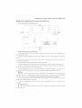
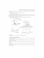
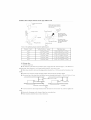
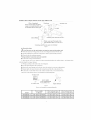
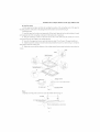
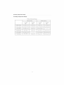
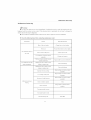
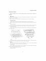
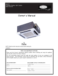
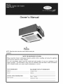
Carrier
Owner's
Manual
NOTE: Read the entire instruction manual before starting the
installation.
NOTE
TO EQUIPMENT
Please read this Owner's
Information
Manual
and keep this manual for future reference.
OWNER:
carefully
before
installing
For your convenience,
please record the model and serial numbers
spaces provided.
This information,
along with the installation
data
will be helpful should your system require maintenance
or service.
UNIT INFORMATION
DEALERSHIP
Model #
Company
Seria! #
Address:
INSTALLATION
Date Installed
INFORMATION
Phone
CONTACT
Name:
Number:
Technician
Name:
and
using
this appliance
of your new equipment
in the
and dealer contact information,
INFORMATION
SAFETY CONSIDERATIONS
Installing, starting up, and servicing air-conditioning
equipment
can be hazardous due to system pressures, electrical components,
and equipment location (roofs, elevated structures, etc.).
Only trained, qualified installers and service
install, start-up, and service this equipment.
mechanics
should
Untrained personnel can perform basic maintenance functions such
as cleaning coils. All other operations
should be performed by
trained service personnel.
When working
on the equipment,
literature
and on tags, stickers,
equipment.
observe precautions
and labels attached
in the
to the
Follow all safety codes. Wear safety glasses and work gloves. Keep
quenching cloth and fire extinguisher
nearby when brazing. Use
care in handling, rigging, and setting bulky equipment.
Read these instructions
thoroughly
cautions included in literature and
local building
codes
special requirements°
safety-alert
and follow N1 warnings or
attached to the unit. Consult
and National Electrical Code
Recognize safety information.
symbol _.
When
(NEC) for
This is the
you see this symbol on the unit and
EQUIPMENT
DAMAGE
HAZARD
Failure to follow
this caution
damage or improper operation.
may result
Do not bury more than 36 in. (914 mm) of refrigerant pipe
in the ground. If any section of pipe is buried, there must be
a 6 in. (152 mm) vertical rise to the valve connections
on
the outdoor units. If more than the recommended
length is
buried, refrigerant may migrate to the cooler buried section
during extended periods of system shutdown. This causes
refrigerant
slugging
and conid possibly
damage
the
compressor at start-up.
SYSTEM
REQUIREMENTS
Allow sufficient space for airflow and servicing unit. See Fig. 1
for minimum required distances between unit and walls or ceilings.
Recommended
Connection
cation WirinRtTo
in instructions or manuals, be alert to the potential for personal
injury.Understand
these signal words: DANGER, WARNING, and
CAUTION.
These words are used with the safety-alert
symbol
DANGER identifies the most serious hazards which will result in
Power
severe personal injury or death.
WARNING
signifies hazards
which could result in personal injury or death. CAUTION is used
to identify unsafe practices which may result in minor personal
injury or product and property damage. NOTE is used to highlight
suggestions which will result in enhanced installation, reliability, or
operation.
Consult
Method
minimize
SHOCK
for Power
communication
and Communi-
wirinRinterfer-
Wiring:
The main power is supplied to the outdoor unit. The field supplied
connecting cable from the outdoor unit to indoor unit consists of
three (3) wires and provides the power for the indoor unit. 'D,vo
wires are high voltage AC power and one is a ground wire.
your
local
building
codes
Electrical Code) or CEC (Canadian
requirements.
All wires must be sized per NEC
ELECTRICAL
in equipment
and
the
Electrical
NEC
Code)
(National
for special
or CEC and !ocal codes.
Use
Electrical Data table MCA (minimum circuit amps) and MOCP
(maximum over current protection) to correctly size the wires and
the disconnect fuse or breakers respectively.
HAZARD
Per caution note, only copper conductors
with a minimum
300 volt
Failure to follow this warning could result in personal
injury or death.
rating and 2/64=inch
Before installing, modifying, or servicing system, main
electrical disconnect switch must be in the OFF
position. There may be more than 1 disconnect switch.
Lock out and tag switch with a suitable warning label.
A separate shielded copper conductor only, with a minimum 300
volt rating and 2/64-inch
thick insulation,
must be used as the
communication
wire from the outdoor unit to the indoor unit.
Communication
thick insulation
must be used.
Wiring:
To minimize voltage drop of the control wire, use the following
wire size and maximum lengths shown in the chart below:
Wire Size
EXPLOSION
HAZARD
Length
ft (m)
18 AWG
50 (15)
16 AWG
50 (15) to 100 (30)
Failure to follow this warning could
result in death, serious personal injury,
and/or property damage.
Never use air or gases containing
oxygen for leak testing or operating
refrigerant compressors.
Pressurized
mixtures of air or gases containing
oxygen can lead to an explosion.
EQUIPMENT
DAMAGE HAZARD
Failure to follow this caution may result in equipment
damage or improper operation.
Wires should be sized based on NEC and local codes.
* Use copper conductors only with a minimum
raring and 2/64 inch thick insulation.
300 volt
User Notice
•
When operating,
the entire capacity of the cooperating
indoor unit should be not larger than
150% of outdoor unit. Otherwise, it will cause the shortage of cooling (heating) capacity.
• A Breaker(or fuse) need to be installed in every indoor unit, and the capacity should in according
with indoor unit's electrical parameter;
all the indoor units are required to be centralized controlled by
a total Switch, this Switch can cut off the electric power supply in case of emergency. The Breaker(or
fuse) on each indoor units have the function of short circuit prevention
it should be connected
in normal situation.
indoor units. Before clearing
and abnormal overload avoiding,
The total switch controlling
and maintenance
the
power supply of all the
job being carried out to the indoor units, it is very
important to turn off the total power supply switch.
•
In order to turn on the units successfully,
the main power switch should be opened 8 hours
before the operation.
• After receiving the turn off signal, every indoor unit will continue to work for 20-70sec to make
use of the rest cool air or the rest heat air in the heat exchanger, while preparing for the next operation.
And this is norlnal.
•
When the selected operating mode of the indoor unit are clash with the operating mode of the
outdoor unit, the 1nail\ruction light will blink after 5s on the indoor unit or remote controller showing
that the operation clash, then the indoor unit will stop. At this time, change the operation mode of the
indoor unit to the one that would not clash with the outdoor operating
mode to make the operation
normah The cooling mode is not clash with the dry mode, while the fan mode is not clash with any
mode.
• The appliance shall not be installed in the laundry.
• An all-pole disconnection
switch having a contact separation of at least 3rain in all poles should
be connected in fixed wiring.
• lnforlnation regarding transport/storage
•
telnperature (- 13 - 131°F/-25-55°C)
is missing.
Main switch provided by end user: main switch handle should be black or gray, it can be locked
in "OFF" position with padlock.
!I, The main disconnection
recomlnended
device should be explained in user manual and the height should be
at 0.6-1.71n. over current protection is required(UL
1995,CSA C22.2).
o
!I, The cooling range of the unit is the outdoor environlnent
telnp.23-118.4
F(-5-48°C)
o
DB, the heating range of
the unit( only for the heat pump type unit) is the outdoor environlnent temp. 5-80.6 F(-15-27°C)
This product
must not be disposed
together
with the domestic
waste. This product
disposed at an authorized place for recycling of electrical and electronic appliances.
WB.
has to be
Contents
Safety lntbrmation
Install
....................................................................................................
of The Compact
Constitutes
Working
and Names
Temperature
Malfunction
Debarring
Maintenance
Method
Panel Cassette
Type Indoor
of Parts of Compact
1
Unit .........................................
Panel Cassette
2
Type Indoor
Unit ...... 10
Range ..................................................................................
11
............................................................................................
12
..............................................................................................
14
Safety
Information
Safety Information
Please read this manual carefully before use this unit, and operate it correctly according
to the guide in
this manuah
Please take specially note to the meaning of these two marks:
A_x Warning!:
This mark means that it may cause casualty or badly heart if the operation is incorrect.
/_'X Note!: This mark means that it may cause casualty or property loss if the operation is incorrect.
Z_X Warning:
•
Do not adopt fuse with unsuitable capacity or adopt iron thread instead of fuse, otherwise malfunction
or fire may happened.
•
Cut down the main power switch immediately
if malfunction
(such as smell the burning odor etc.)
happened.
@ Maintain ventilation to prevent oxygen leakage in room.
@ Don't insert finger or stick like things into discharge vent or outlet grill.
@ Please make sure that the unit is installed in the place that can bear the weight of it adequately. If the
place is not strong enough, the air conditioner
may drop and cause casualty event.
@ Don't spray or smear any oil paint or insecticide on the surface of unit, otherwise, fire may be leaded.
•
Do not refit the conditioner.
Please contact the agency or prefect ional personnel to repair or move the
conditioner.
An all-pole disconnection
connected
switch having a contact separation
of at least 3mm in all poles should
be
in fixed wiring.
A_x Note!:
•
Please check and make sure that the cord, drainage pipe and tubes are connected in the correct way to
prevent leakage of wateL refrigerant, electric shock or fire.
•
The main power must connectable to the earth in order to assure the conditioner
earthing effectively
and to prevent electric shock. Please don't connect the earthing line with the gas pipe, water pipe, lightening
rod or the connecting
•
line of telephone.
The air conditioner
should be turned off at least after 5 rains' operation; otherwise it would affect the
duration of the unit.
@ Don't let the children operate the air conditioner.
@ Please don't operate the unit by wet hand.
@ Please turn off the main power of the unit before cleaning the conditioner or change the filter.
@ Please cut off the main power if the conditioner
will be used for a long time.
Install
Install
of The Compact
Sk Schematic
diagram
Panel
Cassette
of installation
of The Compact
Type Indoor
Panel
Cassette
]ype
Indoor
Unit
Unit
spaces
/
,i
•
E_
t--_m
_--vL
40GJQB12C--3
40GJQB18C--3
unit:in/ram
i
_
::10 14
m i
::(%0mm)i
-
40GJQB24C-_3
Fig.1
"k Select install location of the indoor unit
I. Obstruct should put away from the intake or outlet vent of the indoor unit so that the airflow can be
blown though all the room.
2. Make sure that the installation had accord with the requirement
of the schematic diagram of installation
spaces.
3. Select the place where can stand 4 times of the weight of the indoor unit and would not increase the
operating noise and oscillate.
4. The horizontally
of the installation place should be guaranteed.
5. Select the place where easy drain condensated
coagulated water, and easy connect with outdoor unit.
6. Make sure that there are enough space for care and maintenance.
Make sure that the weight between
the indoor unit and ground is above 70 6/7 in (1800 mm).
7. When installing the steeve bolt, check if the install place can stand the weight 4 times of the unit's. If
not, reinforce before installation.
/_
(Refer to the install cardboard and fi_d where should be reinforced)
Note!
There will be lots of lampblack and dust stick on the acentric, heat exchanger and water pmnp in dining
room and kitchen, which would reduce the capacity of heat exchanger,
operation of the water pmnp. The fbllewing treatment
lead water leakage and abnormal
should be taken under this circumstance:
1. Ensure that the smoke trap above cooker has enough capacity to obviate lampblack
to prevent the
indraft of the lampblack by the air conditioner.
2. Keep the air conditioner
far from the kitchen so that the lampblack
would not be indraft by the air
conditioner.
Important
•
notice:
To guarantee the good performance,
with this instruction.
the unit must be installed
by professional
personnel according
Install of The Compact
Panel
Cassette
'Iype
Indoor
Unit
-k Dimension of ceiling opening and location of the hoisting screw (M 10)
25 3,'5 in (650 ram)
:i:777777777iZ
22 4,'9 in (570 ram)
ZZZT:
:ZII17777777777777777777777777777111111_
i_
"4,
15 3,'4 in (400 ram)
"-
o
Refrigerant
pipe
Ko
o
E _
E
Hoisting
o
o
J
ii
287/9in(6_0mm)(Gaps
between
hoisting
screwrods)j
_# in(8_0 mm!_!n_°°runit_
:i
IInstall
dimension
40GJQB
37 2/5 in (950 ram) (Decorated
surface boards)
of mode
12C--3AOGJQB
_nstallDimension of Mode 40GJQB24C--3
18C--3
Fig.2
'0' The drilling
of holes
in the ceiling
must be done by the professional
installation
personnel.
stands for main body of the unit
ii
ii
Ceiling
,_ _
Abo_e 46 in (20 mm)
Fig.3
Notes: The dimension for the ceiling openings with * marks can be as large as 35 5/6 in (910 mm). But the
overlapping
sections of the ceiling and the decorated
surfime boards should be maintained
at no less than
4/6 in (20 mm).
"it Main body of hoisting air conditioner
1 The primary step for install the indoor unit.
•
i .
35 in(g g0 ram)(Ceiling opening)
When attach the hoisting stand on hoisting screw, do use nut and gasket individually
at the upper and
lower of the hoisting stand to fix it. The use of gasket anchor board can prevent gasket break off..
2 Use install cardboard.
'0' Please refer to the install cardboard about the dimension of ceiling opening.
• The central mark of the ceiling opening is marked on the install cardboard.
screw
(X4)
Installof The
• Install the install cardboard
Compact
Panel Cassette
"Iype
Indoor
Unit
on the unit by bolt (3 piece), and fix the angle of the drainage pipe at the
outlet vent by bolt.
3 Adjust the unit to the suitable install place. (Refer to the fig.3)
4 Check if the unit is horizontal.
•lnner
drainage pmnp and bobber switch are included in the indoor unit, check if4 angle of every unit
are horizontal by water lever. (If the unit is slant toward the opposite of the coagulate water flow, there may be
mali-'unction of the bobber switch and lead water drop.)
5 Backout the gasket anchor board used to prevent gasket break offand tighten the nut on it.
6 Backout the install cardboard.
Nut (supplied at scene)
J
Gasket (attachment)
stand
Gasket anchor board
(attachment)
Tighten (double nuts)
[Fix the hoisting stand firmly]
[Fix the gasket firmly]
on the angle of the drainage sJot
Center'eft 1__
;a;dboa;d
Water lever
.........
Polyethylene
pipe
_
Bolt(attachmenff......
[Fix the install cardboard]
Bolt(attachment)
Fig.4
,_k Note!
Please
do tighten
Connection
•
the nuts and bolts
of the refrigerant
to prevent
air conditioner
break
oft:
pipe
When connect the pipe to the unit or backout it from the unit, please do use both spanner and torque
wrench, as shown in fig.5.
• When connect, smear both inside and outside of the flare nut with freeze motor oil, screw it by hand
and then tighten it with spanner.
•
Refer to _5rm 1 to check if the wrench had been tightened (too tight would mangle the nut and lead
leakage).
•
Examine the connection
pipe to see if it had gas leakage, then take the treatment of heat insulation, as
shown in the fig.5.
• Only use median sponge to entwine the wiring inter_k_ceof the gas pipe and heat preservation
the gas collection tube.
sheath of
InstallofTheCompact
Panel
Cassette
"Iype Indoor
here
Unit
Median sponge (attachment)
(entwine the wiring interface
with seal mat)
Thread fasten(x4)
Torque wrench
Heat preservation
sheath of liquid inlet
tube (attachment) (for
liquid tube)
'ii
_'\
' Flarenut
\\\\,
Gas collection tube
Liquid inlet tube
Wiling"
, interface,
>
Heat preservation
sheath of gas collection
tube (attachment)(for
gas tube)
Fig.5
Form 1: The tightening torque needed for tightening nut
I)iameter
"Jr Drainage
(inch)
Surface
thickness
(in/ram)
Tightening
torque
_pl/4"
_>0.02 in (0.5 ram)
20.34
40.68 ft.lb(15 r 30 N.m)
_p3/8"
_>0.03 in (0.71 ram)
40.68
54.24 ft.lb(30r
_pl/2"
_>0.04 in (1 ram)
61.02
67.8 f_clb(45
_p5/8"
_>0.04 in (1 ram)
81.36
88.14 ft.lb(60
65 N.m)
_p3/4"
_>0.04 in (1 ram)
94.93
101.7 ft.lb(70
75 N.m)
40 N.m)
50 N.m)
hose
1. Install the drain hose
•
The diameter of the drain hose should be equal or bigger than the connection pipe's. ( The diameter of
polythene pipe: Outer diameter i in (25 mm) Surface thickness _>0.06 in (1.5 mm)
•
Drain hose should be short and drooping gradient should at less 1/100 to prevent the formation of air
bubble.
•
li-'drain hose cannot has enough drooping gradient, drain raising pipe should be added.
@' To prevent bent of the drain hose, the distance between hoisting stand should is 3.28 to 4.92 ft (i to 1.5 m).
////////////////////////
////////////////////////
O(Correct) 1/100 or morn gradient
× (wrong)
Fig.6
@ Use the drain hose and clamp attached, lnsert the drain hose to the drain vent, and then tighten the
clamp.
•
Entwine the big sponge on the clamp of drain hose to insulate heat.
•
Heat insulation should be done to indoor drain hose.
Install
of The Compact
Panel Cassette
"Iype
Indoor
Unit
Sponge(attachment)
\\\
Clamp(attachk_)e]_t)_
_._\,
......... Clamp
2>
/
Sponge (gray)
Drain
hose
Below' 1'6 in (4 mm)
Fig.7
Drain stepup pipe note
@ The install height of the drain raising pipe should less than 11 in (280 mm).
@ The drain raising pipe should form a right angle with the unit, and distance to unit should not beyond
300rain.
V_
Ceiling
Clamp(attachment)
Fig.8
Instruction
• The slant gradient of the attached drain hose should be within 3 in (75 mm) so that the drain hole doesn't has
to endure the unnecessary outside force.
Drain hose(attachment )
'
---.....
r'/-/ " _"
E
_g
Fig.9
• Please install the drain hose according to the %llowing
Above 100mm
/
process if several drain hoses join together.
T-tie injoin drain hose
The specs of the selected join drain hose should fits the running capacity of the unit.
Fig. 10
2 Check the smoothness of drain after installation.
@ Check the drain state by ilnlnitting 36 3/5 ins (600 cc) water slowly from the outlet vent or test hole.
@ Check the drain in the state of"refrigerating
after installation of"the electric circuit.
InstallofTheComPact
Panel
Cassette
"Iype
Indoor
Unit
Drain hose
[ Way of immiting ]
Test hole cover
Drain vent for repair use (plastic
stopper is included) (drain the water
in waterspout by this outlet vent)
< Immiting water from the rest hole >
Plastic water pot (The length of the
pipe should be about 4 in (100 mm).)
<Immiting water from the outlet vent terminal >
Fig. 11
Electrical
/_
wiring
Note:The
power of the entire indoor unit must be connected
in outdoor unit.
@ About the electrical wiring, please see the circuit diagram attached with the unit.
@ All the installation of electrical wiring must be done by professional personnel.
@ Please do take the earthing treatment.
Wiring
method of connection
unit and controller
O Connection wiring (communication):
@ Open electric box cover, drag the wiring (communication)from
well individually
the rubber plug A, and impact them
by impact fastener.
@ Wiring according to the indoor side circuit diagram.
@ Fix the impact _hstener after connection.
@ Entwine the small sponge on the electric wire( do entwine it to prevent condensation).
@ hnpact tightly by impact fastener after connection
and then fit on the electric box.
@ Connect the 3 cord rubber wire to the counter terminal of the 3 way terminal board.
The power cord reference Power cord standard recommending
To indoor
table
unit
power supply
3 way terminal board
4 core rubber wire
To outdoor
j/
unit
Impact fastener
Fig.12
Power cord standard recommending
Power
Model
supply
(V.Ph.Hz)
table
Min. Sectional
Area
of Earth Wire(AWG)
Min. Sectional
of Power
Area
Cord(AWG)
40GJQB12C--3
208 203V-IPh-60Hz
ULI015
AWG
18"1
ULI015
AWG
18"3
40GJQB18C--3
208 203V-IPh-60Hz
ULI015
AWG
18"1
ULI015
AWG
18"3
40GJQB24C--3
208 203V-IPh-60Hz
ULI015
AWG
18"1
ULI015
AWG
18"3
Install
of The Compact
Panel
Cassette
"Iype Indoor
Unit
Install the panel
I. Set the panel to the indoor unit body by matching the position of the swing fl@ motor of the panel to
the piping position of the panel to the piping position of the indoor unit as shown by fig. 13.
2. lnstall the panel
@ lnstall the panel on the indoor unit temporarily. When install, hang the latch on the hook that is located
on the opposite side of the swing flap on the panel of the indoor unit. (2 positions)
@
Hang the remaining 2 latches to the hooks on the sides of the indoor unit.(Be careful not to let the
swing motor lead wire get caught in the sealing lnateriah)
@ Screw the 4 hexagon head screws under the latches in about 3/5 in (15 mm). (The panel would rise)
@ Adjust the panel by turning it toward the direction pointed by the arrow as shown in fig. 13, so that the
adjust board connect the ceiling well.
@ Tighten the screws until the thickness of the sealing material between panel and indoor unit reduced to
5-8rain.
@
ttook
Latch
®
_:Swin
®
/
Scaling material
/
in to
•
1,3 in (5 mm
/ (_) ...........................
\
Air outlet vent/'
_Decoration panel
Fig. 13
Notes:
I. Improper screwing of the screws may cause the troubles shown in fig.14.
to 8 mm)
InstallofTheCompact
Panel
Cassette
"Iype Indoor
Unit
2. lfgap still exist between ceiling and decoration panel after tightening the screws, readjust the height of
the indoor unit. (As shown in fig. 15)
If the raising le_,er and drain hose are
not affect_ can acliust the height of"
indoor unit by the hole on the corner
of panel.
......
jGaps
Z;_22122_
are not allowed
Fig.15
"_ After fixing, be sure no gap left between the ceiling and the panel.
3. Wiring of the decoration panel (Fig. 16)
Connect the joints for swing flap motor lead wire (at 2 places) installed on the panel.
At body
/
At body
At pane
,=
Fig.16
/
At pane '
Constitutes
Constitutes
and Names
and Names
of Parts
of Parts of Compact
of Compact
Panel
Panel Cassette
Drainage
Cassette
"I_pe Indoor
Type Indoor
equipmem
Unit
(inside type)
....................................................
Discharge condensate water from
indoor unit when cooling
Drainage
hose
Guide louver
(placed
in air
outlet vent)
Air outlet vent
Air filter, purifier
Connecting
(in
air inlet grille)
Air inlet grille
40GJQBI2C--3
40GJQB
18C--3
40GJQB24C--3
10
pipe
Unit
Working
Working
Temperature
Temperature
Range
Range
Working Temperature Range
Indoor side state
Dry bulb
temp.
Outdoor side stae
Wet bulb
temp.
Rated Cooling
80,6°F(27°C)
66,2°F( t 9°C)
Max. cooling
89,6°F(32°C)
73,4°F(23°C)
Min. cooling
69,8°F(2
t°C)
Dry bulb
temp.
Wet bulb
temp.
95°F(35°C)
75,2°F(24°C)
t t 8,4°F(48°C)
78,8°F(26°C)
59°F( t 5°C)
64,4°F( t 8°C)
--
Rated Heating
68°F(20°C)
59°F( t 5°C)
44,6°F(7°C)
42,8°F(6°C)
Max. heating
80,6°F(27°C)
--
75,2°F(24°C)
64,4°F( t 8°C)
Min. heating
68°F(20°C)
59°F( t 5°C)
5°F( - t 5°C)
3,2°F( - t 6°C)
11
Malfunction
Malfunction
Debarring
Debarring
Z_xWarning!
•
Cut down the main power switch immediately
if maid, ruction (such as smell the burning odor etc.)
happened, and then contact service center. If the abnormal
state is maintained,
the unit may be damaged or
electric shock or fire may be happened.
• Do not refit the conditioner. Please contact service center to repair or move the conditioner.
"k Check
the lbllowing
items
belbre
contacting
Phenomcna
maintenance
Reason
Remedial
Blow of fuse or breaker
Power cut
Air conditioner
Change
Restart
Measures
fuse or close breaker
when thcre is power
supply
doesn't
Don't connect
run at all
Low batteries
with power
of wireless
Wireless
remote
Change
controller
remote control
runs but
Blockage
Blockage
power
well
new batteries
exceed
area
Signal could be received
within 8m
in inlet or outlet vent of
indoor or outdoor
stops immediately
Connect
remote
controller
Air conditioner
center
unit
Clean
out blockage
Clean
out blockage
in inlet or outlet vent of
indoor or outdoor
unit
Adjust settings
hnproper
of temp. setting
Adjust settings
Low setting of fin speed
incorrect
of wind direction
in wireless
remote
controller
in wireless
remote
controller
Adjust settings
in wireless
remote
controller
Abnormal
cooling
or
Door or window
opened
Close
heating
Direct sun burn
Hang curtain or jalousie
windows
'lbo many people
in room
Too many heater in room
Filter blocked
by dirt
12
Clean filter
before
Malfunction
Debarring
"k Instruction
If problem
still cannot found out ai:ter above checking,
please contact
service
center and instruct
phenomena and modeh
"k The tallowing
circumstance
are not malfunction
"Malfnnction"
Reason
Start up unit immediately
Air conditioner
after turned
The overload
off
doesn't
protects
switch
run
Run for about 1 minute
When opening
Mist is blown
makes it
run after 3 minutes delay.
power
without other
actions
fl'om air
The high humidity
air in room is
When cooling
conditioner
cooled
Slight click sound heard once begin
Sound of initialization
running
Hissing
expand
sound heard continuously
Hissing
flowing
in the unit
sound heard when staring or
The sound for gas refl'igerant
stopping
conditioner
for electric
valve
The sound for gas refrigerant
when cooling
Noise is heard fl'om air
rapidly
stops
_OYV
Slight hissing sound heard when
Sound for running
running
of drainage
system
or after running
The grating
Creak sound heard when running
sound caused by expands
or
of panel and other parts for the
after running
change
Dust be blown
for air
conditioner
Started
up after long time's doesn't
of temperature
Dust in indoor
unit be blown out
runs
This is because
Odor gives out fl'om air
when air conditioning,
odors or cigarette
smoke fl'om the
When running
conditioner
room that was sucked
in is discharged
again.
Alter-sales
Service
When having quality or other problems when purchasing air conditioner,
center.
13
please contact the local service
Maintenance
Maintenance
When
Method
Method
air conditioner
won't
be used lbr a long time, please cut off the main power supply
of air
conditioner.
/_
Warning!
•
Do turn off the unit and cut off the main power supply when cleaning the air conditioner,
otherwise
electric shock or harm may happen.
•
It is t5rbidden to wash air conditioner by water rinsing, otherwise electric shock may happen.
Cleaning
air filter
Air filters should be cleaned by professionals
When the usage environment
with propel" operation to ensure personal safety.
has lots of dust, air filter should be cleaned more frequently
(about once 6
months).
1. Open air inlet grille
Loosen two screws on the air inlet grille with a screwdriver. And
pull the 2 handle on air inlet grille at
the same time with the direction showed by arrow in fig.l 7, pull down slowly. (Reverse when closing)
2. Disassembly
air filter
As shown in fig.18, pull the handle behind air inlet grille, raise it and disassembly.
Then discharge the 3
purifier fixed on filter.
er
4"
Fig. 17
Fig. 18
3. Clean
Adopts cleaner or water to wash filter; if the filter is too dirty ( like oil stain on it ), adopts warm water (
lower than t t 3°F(45°C )with" neutral scourer to clean it, then dry it in the shade.
zA_XNote !
Do not clean the flter by hot water whose temp. is higher than t 13°F(45°C)
to prevent t_/de or deformation.
Do not bum it on fire or the filter would catches fire or deformation.
4. lnstall air filter
Fix the 3 purifiers on filter, install filter on the several bulges on top of air inlet grille, pull the handle
behind air inlet grille toward inside to fix filter. As shown in fig. 19.
5. Close air inlet grille (Refer to the 1_ step)
Maintenance
Method
14
Maintenance
Method
Fig.20
Fig.19
"it Clean air inlet grille
1. Open air inlet grille (the same with the Ist step of Clean Air Filter)
2. Take out air filter (the same with the 2nd step of Clean Air Filter)
3. Take out air inlet grille
Open air inlet grille for an angle of 45 °, as shown in fig.20, rise it.
4. Clean
Clean it by pubescence brush, water and neutral cleaning, then throw water or dry it.
z_Note
!
Do not use water above I 13 F(45 C) to wash the panel to prevent fi_de or defSrmation.
5. lnstall air inlet grille (refer to 3rd step)
6. Install air filter (refer to the 4th step of Clean Air Filter)
7. Close air inlet grille (refer to the 1st step)
"it Install and change of air purifier
1. Open air inlet grille (the same the 1st step of Clean Air Filter)
2. Disassembly
purifier
As shown in fig.21, disassembly
air filter, screw out fixing bolts fixed on purifier on filter, then purifier
could be disassembly.
3. Take out the package
sack of static fiber net filter, then install the filter in stand of purifier, and fix
purifier on air filter.
4. Install air filter (the same with the 4th step of Clean Air Filter)
Air
Purifier
Stand
for
Eix
filter
/
filter
.....
purifier
bolt
......
of -_
purifier
Fig.21
15
Maintenance
Function
Method
and usage period for air puril),ing
• Could adsorb CO, CQ, benzene, aldehydes and odor of gasoline etc..
• Could adsorb deleterious material that is smaller than Ivim in aii, as dust, pollen, bacteria, and virus.
•
Usage period is 6 months to 1 year. If it is necessary
to be changed, purchase
new purifier
in the
nearest Gree special engaged maintenance center.
"_ Clean
Outlet
•
Clean
the surface
•
It is forbidden
•
lfthe
guide
Disassembly
,/_
Rotate
guide
louver,
panel
Panel
by soft dry cloth
surface
panel
is too dirty,
install
guide
or wet cloth
by gasoline,
it may be removed
of guide
with neutral
benzene,
scourer.
diluents,
to be cleaned.
cleansing
(As narrated
powder
etc..
below)
louver
louver
in both end of'guide
louver
to loose.
!
Do not wipe
2. Install
Surface
to clean
and
bolts
Note
and
louver
1. Disassembly
Screw
vent
guide
guide
guide
louver
powerfully
when
cleaning,
otherwise
fluffon
surface
would
fall oft:
louver
louver
slightly
and then tighten
'k- Maintenance
before
could
install
the protruding
edge
of both
end into grooves
on both
end of
bolts.
or
alter
usage
season
Check belbre the usage season
• Check if there is blockage in inlet or outlet vent of air conditioner.
• Check if the earthing wire had earthed reliably.
• Check if the air filter had been installed well.
•
In order to start up the air conditioner
smoothly after long time's turned oft, turn on the main power
supply 8 hours before turning on the air conditioner.
Maintenance
alter usage season
• Clean filter and bo@ of air conditioner.
• Cut offthe main power supply of air conditioner.
• The cooling or heating capacity and sound level are tested before leaving fi_ctory.
• If the parameter changed, refer to the data offered on nameplate.
16
Copyright
2014 Carrier Corporation
Manufacturer
reserves
• 7310 W. Morris
the right to change,
St. • Indianapolis,
at any time, specifications
IN 46231
and designs
Edition
without
notice
and without
Date: 11/14
Catalog
No: 40GJC-OIOM
obligations.
Replaces:
New
66129917011