1
®
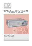
2N StarGate
User Manual
Version
Firmware
5.4
1.16.5
www.2n.cz
The 2N TELEKOMUNIKACE joint-stock company is a Czech manufacturer and supplier of
telecommunications equipment.
The product family developed by 2N TELEKOMUNIKACE a.s. includes GSM gateways, private
branch exchanges (PBX), and door and lift communicators. 2N TELEKOMUNIKACE a.s. has
been ranked among the Czech top companies for years and represented a symbol of stability
and prosperity on the telecommunications market for almost two decades. At present, we
export our products into over 120 countries worldwide and have exclusive distributors on all
continents.
2N® is a registered trademark of 2N TELEKOMUNIKACE a.s.. Any product and/or other
names mentioned herein are registered trademarks and/or trademarks or brands protected
by law.
2N TELEKOMUNIKACE administers the FAQ database to help you quickly find information and
to answer your questions about 2N products and services. On www.faq.2n.cz you can find
information regarding products adjustment and instructions for optimum use and procedures
„What to do if...“.
Declaration of Conformity
2N TELEKOMUNIKACE hereby declares that the 2N® StarGate product complies with all basic
requirements and other relevant provisions of the 1999/5/EC directive. For the full wording
of the Declaration of Conformity see the CD-ROM enclosed and at www.2n.cz.
The 2N TELEKOMUNIKACE company is the holder of the ISO 9001:2009 certificate. All
development, production and distribution processes of the company are managed by this
standard and guarantee a high quality, technical level and professional aspect of all our
Content
Content
1. Product Overview . . . . . . . . . . . . . . . . . . . . . . . . . . . . . . . . . . 5
1.1 Compatibility . . . . . . . . . . . . . . . . . . . . . . . . . . . . . . . . . . . . . . . . . . . . . . . . . . . .
1.2 System . . . . . . . . . . . . . . . . . . . . . . . . . . . . . . . . . . . . . . . . . . . . . . . . . . . . . . . .
1.3 Product Description . . . . . . . . . . . . . . . . . . . . . . . . . . . . . . . . . . . . . . . . . . . . . .
1.4 Innovations . . . . . . . . . . . . . . . . . . . . . . . . . . . . . . . . . . . . . . . . . . . . . . . . . . . . .
1.5 Terms and Symbols Used . . . . . . . . . . . . . . . . . . . . . . . . . . . . . . . . . . . . . . . . .
6
8
17
19
20
2. Description and Installation . . . . . . . . . . . . . . . . . . . . . . . . . . 21
2.1 Plug-In Boards . . . . . . . . . . . . . . . . . . . . . . . . . . . . . . . . . . . . . . . . . . . . . . . . . .
2.2 Antenna and Antenna Splitters . . . . . . . . . . . . . . . . . . . . . . . . . . . . . . . . . . . . . .
2.3 Gateway Rack Configuration . . . . . . . . . . . . . . . . . . . . . . . . . . . . . . . . . . . . . . .
2.4 Installation . . . . . . . . . . . . . . . . . . . . . . . . . . . . . . . . . . . . . . . . . . . . . . . . . . . . .
22
40
47
49
3. Configuration . . . . . . . . . . . . . . . . . . . . . . . . . . . . . . . . . . . . . . 59
3.1 Important Default Settings . . . . . . . . . . . . . . . . . . . . . . . . . . . . . . . . . . . . . . . . .
3.2 Quick Step-by-Step Manual . . . . . . . . . . . . . . . . . . . . . . . . . . . . . . . . . . . . . . . .
3.3 Web Configuration Interface . . . . . . . . . . . . . . . . . . . . . . . . . . . . . . . . . . . . . . . .
3.4 Enhanced CPU Configuration . . . . . . . . . . . . . . . . . . . . . . . . . . . . . . . . . . . . . .
3.5 2N® External Routing Machine . . . . . . . . . . . . . . . . . . . . . . . . . . . . . . . . . . . . .
3.6 2N® SIM Star System . . . . . . . . . . . . . . . . . . . . . . . . . . . . . . . . . . . . . . . . . . . .
60
63
65
114
130
147
4. List of AT Commands . . . . . . . . . . . . . . . . . . . . . . . . . . . . . . . 149
4.1 Basic Commands . . . . . . . . . . . . . . . . . . . . . . . . . . . . . . . . . . . . . . . . . . . . . . . . 150
4.2 Configuration Commands . . . . . . . . . . . . . . . . . . . . . . . . . . . . . . . . . . . . . . . . . . 152
5. Advanced Configuration
. . . . . . . . . . . . . . . . . . . . . . . . . . . . 161
5.1 List of Status Codes . . . . . . . . . . . . . . . . . . . . . . . . . . . . . . . . . . . . . . . . . . . . . .
5.2 Trace . . . . . . . . . . . . . . . . . . . . . . . . . . . . . . . . . . . . . . . . . . . . . . . . . . . . . . . . .
5.3 Tracing . . . . . . . . . . . . . . . . . . . . . . . . . . . . . . . . . . . . . . . . . . . . . . . . . . . . . . . .
5.4 List of LOG Events . . . . . . . . . . . . . . . . . . . . . . . . . . . . . . . . . . . . . . . . . . . . . . .
5.5 CDR Line Description . . . . . . . . . . . . . . . . . . . . . . . . . . . . . . . . . . . . . . . . . . . . .
5.6 SDR Line Description . . . . . . . . . . . . . . . . . . . . . . . . . . . . . . . . . . . . . . . . . . . . .
5.7 Statistics . . . . . . . . . . . . . . . . . . . . . . . . . . . . . . . . . . . . . . . . . . . . . . . . . . . . . . .
5.8 List of SNMP traps . . . . . . . . . . . . . . . . . . . . . . . . . . . . . . . . . . . . . . . . . . . . . . .
162
169
171
172
174
175
176
178
6. Technical Parameters . . . . . . . . . . . . . . . . . . . . . . . . . . . . . . . 180
6.1 2N® StarGate Technical Parameters . . . . . . . . . . . . . . . . . . . . . . . . . . . . . . . . . 181
6.2 2N® BlueTower Technical Parameters . . . . . . . . . . . . . . . . . . . . . . . . . . . . . . . 184
7. Supplementary Information . . . . . . . . . . . . . . . . . . . . . . . . . . 186
7.1 Troubleshooting . . . . . . . . . . . . . . . . . . . . . . . . . . . . . . . . . . . . . . . . . . . . . . . . .
7.2 List of Abbreviations . . . . . . . . . . . . . . . . . . . . . . . . . . . . . . . . . . . . . . . . . . . . . .
7.3 Regulations and Directives . . . . . . . . . . . . . . . . . . . . . . . . . . . . . . . . . . . . . . . . .
7.4 General Instructions and Cautions . . . . . . . . . . . . . . . . . . . . . . . . . . . . . . . . . . .
187
188
190
191
1. Product Overview
In this section, we introduce the 2N® StarGate / BlueTower product, outline its
application options and highlight the advantages following from its use. This section
also includes safety instructions.
Here is what you can find in this section:
1.1 Compatibility
1.2 System
2N® StarGate
2N® BlueTower
1.3 Product Description
1.4 Innovations
1.5 Terms and Symbols Used
2N® TELEKOMUNIKACE a.s., www.2n.cz
5
1.1 Compatibility
This section describes compatibility of the earlier HW versions with the new CPU
version. Obey the instructions included herein to make your 2N® StarGate /
BlueTower system work correctly.
CPU
Serial number
Web interface
New CPU version
M202-xxxxxxxxxxx
YES
SIM Client (SIMStar Server support)
YES
Integrated AUX
SMS sending/receiving account
YES
YES
Earlier CPU version
M112-xxxxxxxxxxx
NO
NO
NO
NO
PRI Board
Use the PRI1/PRI2 card of version PRI132 and higher with the new CPU. Using a PRI card other than that described above may lead to
the 2N® StarGate / BlueTower system malfunction.
VoIP Board
The VIP172 VoIP card can be used both for the ealier and new CPU versions.
AUX Board
The AUX card is no more available in the new 2N® StarGate / BlueTower
system as the AUX inteface is integrated in the CPU. Do not use the AUX card with your new CPU as the AUX card is
not part of the 2N® StarGate / BlueTower system any more.
GSM/UMTS Board
The new CPU is compatible with all the GSM/UMTS cards described in the GSM /
UMTS Board subsection.
2N® TELEKOMUNIKACE a.s., www.2n.cz
6
The following cards only support the 2N® SIM Star service with
the new CPU version. UMTS board with 2 Telit UC864–G engines, 4SIM/channel, 2N® SIM Star support. Part No. 5070553E.
GSM board with 2 Wavecom Q55 (WMP100) engines,
4SIM/channel, 2N ®
5070550E.
SIM
Star support. Part No.
The 2N® SIM Star service is not available with the old CPU
versions for the above mentioned cards.
2N® TELEKOMUNIKACE a.s., www.2n.cz
7
1.2 System
This user manual is designed for two types of gateways. Both the gateways have the
same features and differ in the maximum capacity of the GSM / UMTS channels used.
2N® StarGate
2N® BlueTower
2N® TELEKOMUNIKACE a.s., www.2n.cz
8
2N® StarGate
Basic Dimensions
2N® StarGate is the biggest GSM gateway in the 2N® PRI gateway family. The
system is integrated in a 19" subrack of the height of 3U and depth of 360mm. The
front side is open, equipped with slots for plug–in boards with front panels. The panel
includes the main switch. In case not all GSM / UMTS cards are plugged in, the vacant
front section must be covered with a fixed panel(s).
The whole backside is covered with a panel with a built–in active fan, which is
automatically switched on whenever the power supply temperature exceeds 70°C. The
main power supply unit is located in front of the fan. The bottom and upper sides are
covered by perforated sheet and the assembly flanges are provided with handrails.
The system bus is designed as a printed circuit board (PCB) with DIN connectors and
fitted to the inner subrack carrier profiles.
Front Side Division
The subrack width is divided into an 8HP–wide mains panel and 19x4HP–wide modules
in the following sequence (from right to left):
VoIP version
Fixed panel with a main switch (AC type) or power connectors (DC
type)
8HP
VoIP card
4HP
Basic or enhanced CPU card
4HP
Empty position
4HP
GSM or UMTS cards (one for two GSM / UMTS channels)
Remaining
space (each
4HP)
ISDN version
Fixed panel with a main switch (AC type) or power connectors (DC
type)
8HP
Empty position
4HP
Basic or enhanced CPU card
4HP
1ISDN PRI or 2ISDN PRI card
4HP
GSM or UMTS cards (one for two GSM / UMTS channels)
Remaining
space (each
4HP)
2N® TELEKOMUNIKACE a.s., www.2n.cz
9
ISDN + VoIP version
Fixed panel with a main switch (AC type) or power connectors (DC
type)
8HP
VoIP card
4HP
Basic or enhanced CPU card
4HP
1ISDN PRI or 2ISDN PRI card
4HP
GSM or UMTS cards (one for two GSM / UMTS channels)
Remaining
space (each
4HP)
Examples of Used Types
Figure: Empty 2N® StarGate Rack
Warning
Make sure that the backside jumpers have been connected
properly in the rack to make your system work correctly. Refer
to Gateway Rack Configuration for more details.
2N® TELEKOMUNIKACE a.s., www.2n.cz
10
Figure: 2N® StarGate with 16 GSM Boards, Enhanced Basic CPU, VoIP Interface and
AC Power Supply
Figure: 2N® StarGate with 16 UMTS Boards, Enhanced CPU, 2 ISDN PRI Interfaces
and AC Power Supply
Figure: 2N® StarGate with 16 UMTS Boards, Enhanced CPU, 2 ISDN PRI, VoIP
Interfaces and AC Power Supply
2N® TELEKOMUNIKACE a.s., www.2n.cz
11
The PRI/CPU/VoIP card positions are fixed and may not be
interchanged in the rack.
Note
Please keep all cards in the right positions. Wrong positions will
cause malfunction of the whole system!
In the case of VoIP card replacement by ISDN PRI (and vice
versa) please read the instructions in Section 2.4 Installation.
Power Supply
The system uses an industrial power supply unit with natural cooling and an auxiliary
external fan, which is switched on automatically whenever the power supply
temperature exceeds 70°C. The power supply unit is designed with a 30% reserve
even under the maximum load.
Power supply types
Internal 90 – 260V / 50 – 60 Hz (output 5V / 30A).
2x Internal 90 – 260V / 50 – 60 Hz (output 5V / 30A) (redundant).
Internal 48 DC (output 5V / 30A).
The type of the power supply unit to be used depends on the part number.
Caution
Make sure that the incoming supply is matching the requested
values!
High voltage may cause a serious injury or death!
Tip
You are recommended to connect the gateway to the UPS
system.
2N® TELEKOMUNIKACE a.s., www.2n.cz
12
2N® BlueTower
Basic Dimensions
2N® BlueTower is the smallest of the 2N® PRI gateway family, featuring the
capacity up to 8 GSM / UMTS channels. The system is integrated in a small 19" subrack
of the height of 3U, width of 29HP and depth of 320mm. The front side is open,
equipped with slots for plug–in boards with front panels. The panel includes the main
switch. In case not all GSM / UMTS cards are plugged in, the vacant section of the front
side must be covered with a fixed panel(s). An optional antenna splitter can be
installed.
The whole backside is covered with a panel with a built–in safety–fuse box and power
socket. The main power supply unit is inside the system and is fully designed for
passive cooling. The bottom and upper sides are covered with EMC sheet.
The system bus is designed as a printed circuit board (PCB) with DIN connectors and
fitted to the inner subrack carrier profiles.
Front Side Division
The subrack width is divided into 7x4HP–wide modules in the following sequence (from
right to left):
VoIP version
VoIP card
4HP
Basic or enhanced CPU card
4HP
Empty position
4HP
GSM or UMTS cards (one for two GSM / UMTS channels)
Remaining
space (each
4HP)
ISDN version
Empty position
4HP
Basic or enhanced CPU card
4HP
1ISDN PRI or 2ISDN PRI card
4HP
GSM or UMTS cards (one for two GSM / UMTS channels)
Remaining
space (each
4HP)
2N® TELEKOMUNIKACE a.s., www.2n.cz
13
ISDN + VoIP version
VoIP card
4HP
Basic or enhanced CPU card
4HP
1ISDN PRI or 2ISDN PRI card
4HP
GSM or UMTS cards (one for two GSM / UMTS channels)
Remaining
space (each
4HP)
Please keep the GSM/PRI/CPU/VoIP card positions. The positions
are fixed and may not be interchanged.
4 positions are only designed for the GSM/UMTS cards (from left
to right).
Examples of Used Types
Figure: 2N® BlueTower with 2 UMTS Boards, Enhanced CPU, VoIP Interfaces and
Integrated Antenna Splitter
2N® TELEKOMUNIKACE a.s., www.2n.cz
14
Figure: 2N® BlueTower with 2 UMTS Boards, Basic CPU, 2 ISDN PRI Interfaces and
Integrated Antenna Splitter
Figure: 2N® BlueTower with 2 UMTS Boards, Basic CPU, 2 ISDN PRI, VoIP Interfaces
and Integrated Antenna Splitter
2N® TELEKOMUNIKACE a.s., www.2n.cz
15
Figure: 2N® BlueTower with 4 UMTS Boards, Basic CPU, 2 ISDN PRI, VoIP Interfaces
Note
Please keep all cards in the right positions. Wrong positions will
cause malfunction of whole system!
In the case of VoIP card replacement by ISDN PRI (and vice
versa) please read the instructions in Section 2.4 Installation.
Power Supply
The system uses an industrial power supply unit with natural cooling and an auxiliary
external fan, which is switched on automatically whenever the power supply
temperature exceeds 70°C. The power supply unit is designed with a 30% reserve
even under the maximum load. Power supply types
Internal 90–260V / 50 – 60 Hz (output 5V / 30A).
Caution
Make sure that the incoming supply is matching the requested
values!
High voltage may cause a serious injury or death!
Tip
You are recommended to connect the gateway to the UPS
system.
2N® TELEKOMUNIKACE a.s., www.2n.cz
16
1.3 Product Description
Basic Features
2N® StarGate / BlueTower is a compact yet highly sophisticated system. It supports
full remote supervision and configuration via web interface or using an external modem
over a BRI–ISDN and analogue line, or over a B channel in a PRI–ISDN trunk. The
system has been designed and works with a lot of highly sophisticated functions, which
make it fully client–oriented and highly reliable in cooperation with both GSM networks
and ISDN. In addition, it provides full monitoring and comfortable (web interface)
configuration without functional limitations. Configuration alterations can be made
without resetting, i.e. under full operation. Hot–swappable plug–in GSM / UMTS
boards, which can be swapped under full operation including SIM cards, are a matter of
course. The use of up to eight SIM cards per GSM / UMTS module in combination with
an intelligent SIM card switching tool and detailed statistics upgrade this system into a
powerful LCR tool. There is also support of remote SIM cards ( 2N® SIM Star) and an
external LCR machine (2N® External Routing Machine). High product stability is
achieved by the fact that the gateway is programmed in the ASM, i.e. an OS–FREE
system. The system also features easy installation, simple operation and easy
replacement of defective parts as it is composed of plug–in boards that communicate
independently along system buses. As already mentioned, the system allows for an
easy detection of defective parts, automatic locking against use and easy replacement
(hot–swap). Thanks to the above–mentioned properties, the system can be installed
and configured successfully within one hour!
2N® TELEKOMUNIKACE a.s., www.2n.cz
17
Advantages of 2N® StarGate/BlueTower
Compact size, modularity and hot–swappable solution.
Up to 32 GSM / UMTS modules (8 in BlueTower).
Up to 256 SIM cards in a system (StarGate).
Worldwide use – GSM / UMTS boards support all standard GSM
(850/900/1800/1900MHz) and UMTS (850/1900/2100MHz) bandwidths.
Antenna splitters and a high–gain antenna.
Support of up to two ISDN PRI (DSS1) or one VoIP (SIP) connections.
Sending / receiving SMS.
A large memory for detailed Call Data Records (CDR).
Detailed call statistics generating.
Quick start – being free of an operating system (programmed in the processor
code), the system is completely ready within 30 seconds after power on/restart.
Of course, the full function time of all GSM modules depends on the current load
and capacity of the GSM networks to which the gateway is connected.
Intelligent call processing – Least Cost Routing (LCR), SMS and Voice CallBack,
Auto CLIP routing, DISA dial–in.
Intelligent selection of GSM / UMTS module to be used.
Support of remote SIM card function (2N® SIM Star).
Possibility to replace internal LCR with an external solution (2N® ERM).
Remote control, configuration and firmware upgrade.
High connection rate and ASR, low PDD.
AoC support.
Direct connection to GSM modules via Telnet protocol.
SNMP error traps (eCPU).
FTP access to download CDR, SDR (eCPU).
Support of lock with defined BTS.
2N® TELEKOMUNIKACE a.s., www.2n.cz
18
1.4 Innovations
If you program your 2N®StarGate / BlueTower parameters by means of a
computer, you need a web browser (when using the CPU web interface). For the most recent firmware version refer to www.2n.cz and for necessary
instructions see the Others - Update subsection hereof.
At www.2n.cz you will also find the most recent version of this manual in the
popular PDF format. We recommend you to use it especially in connection with
the firmware upgrade as it introduces new useful functions.
Preliminary information on functions that are not yet available is typed on a light
grey background or is printed in grey letters instead of black ones.
2N® TELEKOMUNIKACE a.s., www.2n.cz
19
1.5 Terms and Symbols Used
Manual Symbols
The following symbols and pictograms are used in the manual:
Safety
Always abide by this information to prevent persons from
injury.
Warning
Always abide by this information to prevent damage to the
device.
Caution
Important information for system functionality.
Tip
Useful information for quick and efficient functionality.
Note
Routines or advice for efficient use of the device.
Future Functions
A grey-marked text in this document specifies the 2N® StarGate/BlueTower function
s that will be supported in the future.
2N® TELEKOMUNIKACE a.s., www.2n.cz
20
2. Description and Installation
This section describes the 2N® StarGate/BlueTower product and its installation. Here is what you can find in this section:
2.1 Plug-In Boards
Basic CPU Board
Enhanced CPU Board
GSM / UMTS Board
PRI Board
VoIP Board
2.2 Antenna and Antenna Splitters
2.3 Gateway Rack Configuration
2.4 Installation
2N® TELEKOMUNIKACE a.s., www.2n.cz
21
2.1 Plug-In Boards
All the plug-in cards have defined positions in the system rack. Please keep all cards in
their respective positions. Wrong positions may cause malfunction of the whole system.
The type and quantity of the cards used in your 2N® StarGate / BlueTower gateway
depend on the part number of the gateway and other components.
Note
All the status LEDs (as described below) provide basic status
information only. For detailed information use the terminal or
web interface.
Here is what you can find in this section:
Basic CPU Board
Enhanced CPU Board
GSM / UMTS Board
PRI Board
VoIP Board
2N® TELEKOMUNIKACE a.s., www.2n.cz
22
Basic CPU Board
The basic CPU board carries only the main CPU, which supports all basic features of the
gateway (web interface, 2N® SIM Star support, SMS) . The advanced features of the
enhanced version (SMS2Outlook, SNMP, SMS/Call simulator) are not available.
Board Description
The CPU board contains a processor system controlling the whole system. The board is
designed on a 4–layer PCB of the size of 160x100mm. A simple COM1 serial interface,
an Ethernet connector (100Base–T) and 5 board status LED indicators are located on
the front panel.
1. Indicates board supply; the LED is green if the gateway is powered on and shows
no malfunction.
2. Indicates board initialisation or malfunction.
3. Indicates CDR memory (not shining = empty; flashing 1:1 = 50% full memory;
shining = 100% full memory.
4. 1st serial interface of the basic CPU.
5. 10BaseT Ethernet connection of the basic CPU. COM1 Serial Interface Parameters
The COM1 interface is used as a local port for temporary connection of a PC (terminal)
for installation and servicing purposes and permanent connection of the SMS server
(supervision PC). It provides local monitoring, configuration, tracing and firmware
upgrade. 2N® TELEKOMUNIKACE a.s., www.2n.cz
23
Transmission rate: 57.6 kbps
Bit format: start, 8bit, stop (no parity)
Signals: RXD, TXD, RTS, CTS, GND
Configuration Jumpers
The figure below shows the CPU configuration jumper. The JP1 jumper can be
connected in one of the following three positions.
CPU – COM1 communication port is active for communication with the CPU.
eCPU – COM1 communication port is active for communication with the eCPU.
DEF – used for CPU default reset.
Figure: Configuration Jumpers
2N® TELEKOMUNIKACE a.s., www.2n.cz
24
Enhanced CPU Board
The enhanced version of the CPU board carries two boards with a main CPU and an
extension unit. The main CPU and extension unit have a dedicated Ethernet connector
and share a serial interface (switchable by the jumper located on the main CPU board).
The enhanced CPU board supports all the basic CPU features and some additional
features:
Graphic web interface.
Support of the SMTP and POP3 protocols for sending / receiving SMS.
CDR downloader (an SD card is required).
SMS and Call simulator.
SNMP remote control.
FTP access for CDR and SRD.
Some features can be limited by the licence file. For detailed information please read
the Gateway Control subsection.
Board Description
The board is designed on a 4–layer PCB of the size of 160x100mm. There is also an
extension card located on the main PCB. The board has one simple COM1 serial
interface shared by both the CPUs, two Ethernet connectors (CPU=100Base–T and Ext.
unit=100Base–T), and 10 board status LED indicators on the front panel.
1. Indicates board supply. The LED is green in case the gateway is powered on and
shows no malfunction.
2. Indicates board initialisation or malfunction.
3. 2N® TELEKOMUNIKACE a.s., www.2n.cz
25
3. Indicates CDR memory (not shining = empty; flashing 1:1 = 50% full memory;
shining = 100% full memory).
4. Shared serial interface. To switch to the basic CPU connect JP1 on the main CPU
card.
5. 100Base–T Ethernet interface of the basic or enhanced CPU board.
6. Indicates (shining) that the extension unit is powered on. 7. Indicates (shining) that the extension unit's CPU is IDLE.
8. Indicates (flashing 1:1) that the CPU is not stopped.
9. Shared serial interface. To switch to the basic CPU connect JP1 on the main CPU
card.
10. 100BaseT Ethernet interface of the extension unit of the enhanced CPU board.
COM1 Serial Interface Parameters
The COM1 interface is used as a local port for temporary connection of a PC (terminal)
for installation and servicing purposes and permanent connection of the SMS server
(supervision PC). It provides local monitoring, configuration, tracing and firmware
upgrade.
In the case of switch JP1, switch the COM1 interface to Ext. unit where you find the
console menu for basic Ext. unit IP settings. To locate JP1 please check the figure in
the Configuration Jumpers subsection below.
Basic CPU Connection
Transmission rate: 57.6 kbps
Bit format: start, 8bit, stop (no parity)
Signals: RXD,TXD,GND
Ext. Unit Connection
Transmission rate: 115.2 kbps
Bit format: start, 8bit, stop (no parity)
Signals: RXD,TXD,GND
Configuration Jumpers
There are two configuration jumpers on the enhanced CPU board. JP1 is intended for
switching the serial port between the CPU board and an optional extension board. JP2
is designed for restoring default settings of the enhanced CPU. JP2 is located on the
upper PCB. To restore the default values follow the steps below:
Switch off the GSM gateway.
Remove the CPU card and connect JP2.
Insert the CPU card and switch on the GSM gateway.
Wait for one minute and switch off the GSM gateway again.
Remove the CPU card and release JP2.
Insert the CPU card and switch on the GSM gateway.
Now the factory settings are restored on the enhanced CPU.
2N® TELEKOMUNIKACE a.s., www.2n.cz
26
Tip
To restore the factory settings you can also get connected to the
serial console and select the Factory reset option.
Figure: Configuration Jumpers
2N® TELEKOMUNIKACE a.s., www.2n.cz
27
GSM / UMTS Board
eBoard Description
The GSM / UMTS board contains two GSM or UMTS wireless modules, circuits for their
connection to the PCM bus, and DTMF receivers (+CPU in the case of board with the 2N® SIM Star support). The board is designed on a 4–layer PCB of the size of
160x100mm. Pins 1 and 32 are approximately 1 mm longer in the GSM board system
connector and are used for 'hot swap' power feeding, allowing to push the board in and
out even during operation. This feature is especially handy while installing or replacing
SIM cards. Two SMA antenna connectors and 5 board status indicators are located on
the front panel.
1. PWR – Board supply indication
Shining: Switched on.
Flashing: Board in the sleep mode.
2. INIT – Board initialisation indication
Shining: Board faulty or not yet initialised.
Flashing: Board initialisation failure or system incompatibility.
3. SLP – Board sleep state indication
Shining: Both wireless channels manually blocked.
4. CH1/CH2 – Wireless engine state indication
Shining RED: Wireless engine blocked or switched off.
Flashing RED: Wireless engine restart in progress.
Shining GREEN: Proceeding call.
Flashing slowly GREEN: Call terminating or voice settings in progress.
2N® TELEKOMUNIKACE a.s., www.2n.cz
28
4. Flashing quickly GREEN: Wireless engine trying to log in.
Light off: Wireless engine ready for calling.
5. SMA female antenna connector of wireless engines
Tip
For an easy SIM card replacement, all GSM / UMTS boards are
designed as hot–swappable units.
Board Types
The 2N® StarGate / BlueTower gateway can use several types of GSM or UMTS
boards. The board specification includes the type of wireless device(s), count of SIM
cards channel and 2N® SIM Star support data.
Table of available GSM / UMTS cards (2013):
Order No.
GSM / UMTS card
5070554E
GSM board with 2xTelit GE910 engines, 4SIM/channel, 2N® SIM Star
support
5070078E
GSM board with 2xTelit GE910 engines, 1SIM/channel, 2N® SIM Star
support
5070551E
GSM board with 2 Cinterion MC55i engines, 4SIM/channel, no 2N® SIM
Star support
5070082E
GSM board with 2 Cinterion MC55i engines, 8SIM/channel, no 2N® SIM
Star support
5070077E
N/A
N/A
N/A
N/A
N/A
GSM board with 2 Cinterion MC55i engines, 1SIM/channel, 2N® SIM Star
support
GSM board with 2 Wavecom Q55 (WMP100) engines, 4SIM/channel, no 2N® SIM Star support
GSM board with 2 Wavecom Q55 (WMP100) engines, 8SIM/channel, no 2N® SIM Star support
GSM board with 2 Wavecom Q55 (WPM100) engines, 1SIM/channel, 2N®
SIM Star support
GSM board with 2 Wavecom Q55 (WMP100) engines, 4SIM/channel, 2N®
SIM Star support, N/A.
UMTS board with 2 SierraWireless MC8790V engines, 4SIM/channel, no 2N® SIM Star support
N/A
UMTS board with 2 SierraWireless MC8790V engines, 1SIM/channel, 2N®
SIM Star support
5070553E
UMTS board with 2 Telit UC864–G engines, 4SIM/channel, 2N® SIM Star
support
5070555E
UMTS board with 2xTelit HE910 engines, 4SIM/channel, 2N® SIM Star
support
2N® TELEKOMUNIKACE a.s., www.2n.cz
29
Note
The GSM / UMTS boards can be locked for use in defined GSM /
UMTS networks only. For additional information please ask your
system supplier.
¨
Figure: SIM Card Positions on 4SIM/Channel Boards
2N® TELEKOMUNIKACE a.s., www.2n.cz
30
Figure: SIM Card Positions on 8SIM/Channel Boards
2N® TELEKOMUNIKACE a.s., www.2n.cz
31
Figure: SIM Card Positions on 1SIM/Channel Boards
2N® TELEKOMUNIKACE a.s., www.2n.cz
32
Figure: SIM Card Positions on 4SIM/Channel Boards
2N® TELEKOMUNIKACE a.s., www.2n.cz
33
PRI Board
Board Description
The PRI board contains one or two (depends on the part number) ISDN interfaces and
PCM bus timing circuits. PRI 1 is designed as an internal interface (with an activated
LCR function) and PRI 2 as an external interface (all calls from the port are always
routed to PRI 1). The interface can work in the MASTER or SLAVE mode (set the PRI 1
mode using the web interface and PRI 2 has always the opposite mode). The output
can be configured as TERMINAL (TE) or NETWORK (NT) by jumpers (switching of wires
– for software switch you have to use the web interface!). The settings of these
jumpers HAVE TO match the PRI configuration – two NT and TE modes will cause
malfunction of the PRI board or back–up connection* ! The board is designed on a
4–layer PCB of the size of 160x100mm. There are also 5 (or 8 in 2ISDN PRI) board
status indicators, which are located on the front panel.
The PRI board contains four switches (can be deactivated by jumpers), which
provide hardware connection between PRI 1 and PRI 2 in case the system is
switched off or inoperative. 1. Board supply indication
Shining: Switched on
Flashing: Board in the sleep mode
2. Board supply indication
Shining: Switched on
Flashing: Board in the sleep mode 3. Status of ISDN layer 3 on PRI 1/2 interfaces
Shining: One or more calls are connected over selected interface
2N® TELEKOMUNIKACE a.s., www.2n.cz
34
3. Flashing: B–channel in restartLight off: No active call
4. Status of ISDN layer 2 on PRI 1 (2) interfaces:
Shining: Layer 2 successfully established
Flashing: Layer 2 in the establishing process
Light off: Layer 2 disconnected
5. Status of ISDN layer 1 on PRI 1 (2) interfaces:
Shining: Layer 1 successfully established
Flashing: Layer 1 in the establishing process
Light off: Layer 1 disconnected
6. Physical RJ45 connectors for ISDN PRI 1 and PRI 2 interfaces. Before you plug in
your ISDN connection please check whether the wiring configuration matches the
ISDN connection requirements!
Tip
The LED statuses provide basic information on the ISDN
interface only. For details on the ISDN interface state refer to
the web interface.
Configuration Jumpers
2N® TELEKOMUNIKACE a.s., www.2n.cz
35
There are three configuration jumper blocks on the PRI board. JP2 and JP3 are used for
hardware switching of the ISDN PRI connector into the TE / NT configuration. This
operation means only swapping of the transmitting and receiving connector pairs, the
interface configuration must be made using the web interface. With jumper JP4 you can
activate/deactivate the back–up connection between PRI 1 and PRI 2 in case the
system is switched off or the PRI board is not handled by system. Warning
The back–up connection (JP4) works only in case the wire
settings of PRI 1 (JP3) and PRI 2 (JP2) are set in the opposite
way (e.g. PRI 1 as NT, PRI 2 as TE).
Note
Boards with just one PRI interface (1PRI boards) have the same
settings as the PRI 1 interface on 2PRI boards. And there is no
back–up connection (JP4) either.
Positions of Tx and Rx Wires
Example of Connection with 1ISDN PRI Board
2N® TELEKOMUNIKACE a.s., www.2n.cz
36
Example of Connection with 2ISDN PRI Board
Warning
The ISDN port mode (TE or NT) and synchronisation type
(Master/Slave) must be different on the PBX (PSTN) and on the
gateway. The TEI number must have the same value (default =
0).
2N® TELEKOMUNIKACE a.s., www.2n.cz
37
VoIP Board
Board Description
The VoIP board contains a digital signalling processor (DSP), 4x10/100BaseT Ethernet
switch and a small carrier board with the licence chip. The main board is designed on a
6–layer PCB of the size of 160x100mm. Two board status LED indicators are located on
the front panel. Configuration (e.g. used voice codecs, IP setting) is completely
managed by the main CPU and made via a standard web interface. There is no fixed
memory (EEPROM) for the VoIP card firmware. The firmware is saved on the basic CPU
and uploaded to the VoIP card upon every VoIP card start / restart.
1. PWR – board supply indication
Shining: Switched on
Flashing: Board in the sleep mode
2. INIT – board initialisation indication
Shining for two minutes: Firmware uploading and configuration in progress
Continuous shining: Board initialisation failure
Light off: Board initialised successfully
3. Four RJ45 connectors of the internal 10/100BaseT Ethernet switch
The VoIP board is designed as a media gateway. It works only with media packets
(RTP); signalling packets (SIP) must be routed to the basic CPU IP address.
2N® TELEKOMUNIKACE a.s., www.2n.cz
38
Tip
You have to restart the VoIP card upon any VoIP configuration
change.
Caution
For a successful VoIP card initialisation, the VoIP board MAC
address has to be filled in correctly and the basic CPU must be
switched to the VoIP–SIP mode and contain the VoIP firmware
file.
The integrated Ethernet will not work until the VoIP card has
been initialised successfully.
Configuration Jumpers
There are no configuration jumpers on the VoIP card. Example of Correct VoIP Interface Connection
2N® StarGate / BlueTower
2N® TELEKOMUNIKACE a.s., www.2n.cz
39
2.2 Antenna and Antenna Splitters
2N offers several antenna splitter and antenna models providing the best signal quality
on all GSM / UMTS engines. All the systems are designed for all UMTS and GSM
networks.
Antenna Splitter
The antenna splitter is designed for decreasing the number of antennas, antenna
cables, outdoor antennas and roof mounting space. The antenna splitter is a passive
unit suitable for GSM / UMTS gateways. The antenna splitter can be external (2N®
StarGate) or internal (2N® BlueTower). Each splitter consists of one or more passive
units, each of which has four / two inputs and one output.
Number of
inputs
32
Number of
outputs
2
Input–Output insertion
loss
<15 dB
Unit
high
2U
32
4
<11 dB
2U
32
8
<8 dB
2U
16
1
<15 dB
1U
16
2
<11 dB
1U
16
4
<8 dB
1U
12
3
<8dB
1U
Table: Standard External Antenna Splitter Configurations
Number of
inputs
4
Number of
outputs
1
Input–Output insertion
loss
<
Unit
high
3U
Table: Internal Antenna Splitters for 2N® BlueTower
2N® TELEKOMUNIKACE a.s., www.2n.cz
40
Parameters
Connector type
Value
Note
Input connector
SMA type, female
Output antenna connector
N type, female
RF parameters
Impedance
50 Ohm
Frequency
850 – 2100 MHz
Insertion loss
< 8, 11, 15 dB
According to configuration
Isolation between two channels
> 20 dB
Output overvoltage protection
Device type
Gas surge arrester
Protected voltage level
90 V
Peak current
10 KA
Insertion loss
0.2 dB
Table: Technical Parameters of Antenna Splitters
Splitter Examples
Figure: Internal Antenna Splitter for 2N® BlueTower
2N® TELEKOMUNIKACE a.s., www.2n.cz
41
Figure: External Antenna Splitter for 2N®StarGate
Directional Antenna
The high–gain directional YAGI antenna is suitable for outdoor and indoor use. Type
CPY 9214
Number of elements
14
Frequency
824 – 896, 1770 – 2100 MHz
Gain
9.5 dB / 13 dB
Cable
RG 58, 10m
V.S.W.R
< 1.5 : 1
Connector
N type, female
Table: Basic Parameters of Directional Antenna
2N® TELEKOMUNIKACE a.s., www.2n.cz
42
Figure: Directional Antenna
Figure: Example of Correct Installation of Directional Antennas
Warning
The antenna has to be placed in accordance with the applicable
overvoltage protection and grounding safety rules.
2N® TELEKOMUNIKACE a.s., www.2n.cz
43
Omni-Directional Antenna
The omni–directional antenna is suitable for outdoor use. Type
KA 2290. 9214
Frequency
870 – 960, 1710 – 2170 MHz
Gain
3 dB
Polarization
Vertical
Radiation angle in E–plane
30°
Radiation angle in H–plane
omni–directional
V.S.W.R
< 1.7
Length
420 mm
Weight
0.6 kg
Connector
N female
Table: Basic Parameters of Antenna
2N® TELEKOMUNIKACE a.s., www.2n.cz
44
Discreet Antenna
The small omni–directional antenna is designed for indoor use and provides a good
GSM / UMTS signal quality.
Type
Car antenna
Gain
2.5dB
Cable
Coax cable 174A (5 m)
Connector
SMA (male)
Table: Basic Parameters of Discreet Antenna
Figure: Discreet Antenna
2N® TELEKOMUNIKACE a.s., www.2n.cz
45
Directional Antenna Connection Cable
2N offers you a special low-attenuation cable in variable lengths. The cable terminating
connectors are of the N type.
Type
H1000 PE coax cable
Impedance
50Ω
Operating frequency
5 – 2150 MHz
Used connectors
N type (female)
Cable size
10.3mm
Operating temperature
–40°C to +80°C
Total weight
120g / m
Minimum installation temperature
–5°C
Minimum static bend radius
75mm
Attenuation at 860MHz
14.1dB / 100m
Attenuation at 1000MHz
15.3dB / 100m
Attenuation at 1750MHz
21.3dB / 100m
Attenuation at 2050MHz
23.4dB / 100m
2N® TELEKOMUNIKACE a.s., www.2n.cz
46
2.3 Gateway Rack Configuration
The 2N® StarGate / BlueTower gateways use different hardware rack types. For
detailed information on the differences refer to the 1.2 System subsection All the
systems can be distributed with a VoIP, ISDN or VoIP+ISDN interface. The main back
bus located in the gateway hardware rack is pre–configured to a defined type of
interface (VoIP, PRI and VoIP+ISDN). There are six jumpers on the main bus between
the 3rd and 4th connector (from the right).The jumper lay-out shown below applies to
all the connection types (VoIP, ISDN, VoIP+ISDN).
Keep the jumpers connected as shown below to make your
system work properly.
There are three setting options:
1. ISDN: The gateway is configured to work with the ISDN PRI card only as shown
in the figure below:
2N® TELEKOMUNIKACE a.s., www.2n.cz
47
2. VoIP: The gateway is configured to work with the VoIP card only as shown in the
figure below: 3. VoIP+ISDN: The gateway is configured to work both with the VoIP and ISDN PRI
cards.
Caution
Wrong jumper positions may cause malfunction of the whole
system! Please make changes only if the system is powered off!
Note
The jumper settings are identical for all the gateway types (2N®
StarGate / BlueTower).
2N® TELEKOMUNIKACE a.s., www.2n.cz
48
2.4 Installation
Product Completeness Check
Before installing this product, check whether the delivery is complete according to the
following packing list and read this manual thoroughly. The manufacturer cannot be
held responsible for any damage incurred due to an incorrect use of this product in
contradiction with this manual. The warranty terms do not cover damage to the
product caused by rough handling, incorrect storage or exceeding the quoted technical
parameters.
Item
Power cable 2.5m
Rack with AC power supply Rack with DC power supply
1
–
Mounting set
1
1
Quick Start manual 1
1
Serial 9F–9F cable
1
1
Table: Basic Packing List Items
1PRI
card
Included device
2PRI
card
VoIP
card
Basic CPU
card
Enhanced CPU
card
Ethernet cable
3m
1
2
1
Ethernet cable
0.6m
1
2
Table: Additional Packing List Items
Tip
The packing lists are the same for all the gateway types (2N®
StarGate/ BlueTower).
Installation Conditions
The following conditions must be met during system installation:
Appropriate location (enough free space).
GSM / UMTS signal intensity (minimum recommended signal level : –80dB). You
can use the NET monitor on a mobile phone (e.g. Nokia, Siemens) or the
diagnostics screen in the web interface for measuring the GSM / UMTS signal
intensity.
Unoverloadable GSM / UMTS cells to which the gateway modules are logged in;
please keep in mind that up to 30 calls are set up at a time during full traffic
2N® TELEKOMUNIKACE a.s., www.2n.cz
49
(according to the gateway configuration).
No strong electromagnetic radiation is allowed on the system installation site.
No strong electromagnetic reflections are allowed on the antenna installation site.
The ISDN PRI connection must be configured properly and meet the ITU–T
Q.931–EDSS1 and related recommendations.
The VoIP – SIP signalling must meet the required RFCs.
Place the gateway into an environment that complies with the gateway working
conditions (an air conditioned room or installation rack).
An appropriate (according to the power supply unit used) power feeding with
overvoltage protection and an on–line UPS are recommended.
An Ethernet connection on the installation site is advisable for comfortable
gateway administration.
All the SIM cards to be used must have the same PIN code (or deactivated PIN
code) and be activated by the GSM / UMTS provider.
Warning
The outdoor antenna cable has to be connected according to the
overvoltage protection and grounding safety rules.
High temperatures on the installation site may cause short–time
or permanent gateway errors!
Warning
Do not cover the top, bottom and rear sides of the gateway to
avoid overheating and gateway error!
Protection against humidity and extreme temperatures: The
appliance may never be placed close to heat sources (radiators)
or places exposed to direct sunshine. Also places with high
humidity (such as bathrooms and cellars), places with significant
temperature fluctuation (next to doors, windows), dusty places
(workshops) and places exposed to aggressive gases
(accumulator rooms, boiler rooms) as well as places with
intensive vibrations and places exposed to shocks (compressor
rooms, heavy industrial operations) should be avoided. The
system should be installed horizontally.
VoIP Connection
All the gateway types have the same features. The only difference lies in the number of
simultaneous calls through the VoIP card.
2N® TELEKOMUNIKACE a.s., www.2n.cz
50
Voice codec support
G.711u , G.711a , G.723 at 6.3/5.3bps ,
G.729a,b
Default RTP ports
8000 – 8998 (adjustable by web interface)
Supported signalling
SIP
Default IP port for signalling
5060 (adjustable by web interface)
STUN protocol
Supported IP address check
Interface for SIP
10BaseT Ethernet interface on basic CPU
card
Interface for RTP streams
10/100BaseT Ethernet interface on VoIP
card
Maximum number of simultaneous
calls
2N® StarGate
30
2N® BlueTower
8
The VoIP board is designed as a media gateway. It works only with media packets
(RTP); signalling packets (SIP) must be routed to the basic CPU IP address.
TIP
You have to restart the VoIP card upon any VoIP setting change.
Caution
For a successful VoIP card initialisation, the VoIP board MAC
address has to be filled in correctly and the basic CPU must be
switched to the VoIP–SIP mode and contain the VoIP firmware
file.
The integrated Ethernet will not work until the VoIP card has
been initialised successfully.
ISDN PRI Connection
The gateway can contain a PRI card with one or two ISDN PRI interfaces (depends on
the part number). PRI 1 is always set as an internal interface (PBX connection) and PRI
2 as an external interface (PSTN connection). The Least Cost Routing (LCR) and
additional routing mechanisms are activated on the internal interface. All incoming calls
to the external interface are always routed directly to the internal interface.
2N® TELEKOMUNIKACE a.s., www.2n.cz
51
Interface
ISDN PRI (E1 frame)
Signalling
Q.931 – EDSS1
Signalling channel
(D–channel)
16.
Network interface type
NT or TE (adjustable by web interface)*
TEI number
0 – 63 (adjustable by web interface)
CRC on Layer 1
Activated / deactivated (adjustable by web
interface)*
Connector type
Switchable RJ45 (see Subs. 2.1)
Supported voice codec
G.711a**
Supported B–channel
services
Only voice**
*The PRI 2 interface is always of the opposite type than the PRI 1 interface.
**Other streams are sent directly to the opposite PRI interface.
Installation Examples
There is an exact time source for synchronisation of the PRI interface lines on the PRI
board. Even if you have synchronisation problems on the installation site (caused by
specific and probably ill–configured PBXs with more that one active PRI interfaces),
there is a solution as shown below. Before using this solution you are recommended to
configure your PBX properly, or use the DialThru function. Red lines are calls to the
PSTN, orange lines are calls to GSM / UMTS networks.
Figure: DialThru Function Installation
2N® TELEKOMUNIKACE a.s., www.2n.cz
52
Figure: 1ISDN PRI Card Installation
External Synchronisation Option
There is an exact time source for synchronisation of the PRI interface lines on the PRI
board. Even if you have synchronisation problems on the installation site (caused by
specific and probably ill–configured PBXs with more that one active PRI interfaces),
there is a solution as shown below. Before using this solution you are recommended to
configure your PBX properly, or use the DialThru function.
Figure: Unnormalised External Synchronisation
Connect only Tx wires to the 2PRI board because the ISDN PRI line is not designed for
point–to–multipoint solutions (more than two devices on one ISDN line) like the BRI
ISDN line. This solution is substandard! In case you detect a problem on the line
between the PBX and PSTN (due to an additional connection to the PRI 2 interface),
please disconnect PRI 2 from the line. These problems may be caused by changes in
the line impedance.
Note
Connecting Tx wires only (from the PSTN point of view) to the
PRI 2 interface has no influence on signalling and voice calls.
The PRI board just takes synchronisation pulses from the line.
2N® TELEKOMUNIKACE a.s., www.2n.cz
53
Tip
For an external synchronisation line you can use a standard
cable with an RJ45 connector. To disconnect the Rx wires just
release the defined jumpers on the PRI 2 interface on the PRI
board.
Simultaneous Use of PRI ISDN and VoIP Cards
The GSM gateway enables the VoIP and PRI ISDN interfaces to be used at the same
time. This configuration requires additional incoming/outgoing call routing settings.
Figure: Installation with SIP proxy (Cisco Call Manager).
Licence Limitations
Some of the 2N products have time–limited software licences (e.g. DSS1 signalling,
etc.). Moreover, every gateway restart adds one hour to the internal licence counter.
To see the current licence status, use the CPU web interface (the standard licence
validity is 850 hours).
You are recommended to contact your dealer before licence expiration to request for a
new licence key to increase the gateway using time.
To upload a new licence code, use the CPU web interface.
Caution
A gateway with an expired licence fails to accept calls from the
VoIP/GSM/UMTS/PRI interface because the call control layer is
deactivated.
2N® TELEKOMUNIKACE a.s., www.2n.cz
54
GSM / UMTS Network Restriction
Upon the dealer's request, 2N can activate restrictions of use for selected wireless
networks only. Thus, the gateway will be unable to log in successfully to the restricted
wireless networks. This state is signalled by the red status LEDs on the GSM / UMTS
cards and the 'netw–err' message on the web interface diagnostics screen.
Tip
To prevent this problem consult ask your dealer.
Basic CPU Firmware
Before installing your 2N® StarGate / BlueTower gateway, please upload new
firmware to both the CPUs. Find the latest firmware version plus all software on the
enclosed CD or on our website www.2N.cz.
Warning
To avoid gateway error please use only the firmware files that
are designed for your type of gateway and certified by 2N.
Follow the instructions below to download firmware easily using the gateway
web interface:
Connect your PC and the gateway into the Ethernet network.
Open the web browser (MS Internet Explorer 9 and higher or Mozzila Firefox 4
and higher are recommended).
Enter http://IP_address to register to the web interface.
Click on Upgrade, then on Browse and select the new firmware file.
Click on the Download firmware icon in the lower part of the web page.
2N® StarGate / BlueTower will upgrade the firmware automatically.
Tip
You can also use 2N® SIM Star Server for remote upgrades for
all connected gateways.
Potential Problems of GSM / UMTS Networks
The 2N gateway works reliably even under a 100% load. The following problems may
be caused by GSM networks:
Wireless modules cannot log in, log in slowly, or log out occasionally.
This problem may be caused by any of the following situations:
The GSM / UMTS signal is low. We recommend the minimum signal level of
approximately –80dBm. If lower, you have to change the antenna or
gateway location!
The GSM / UMTS cell (BTS) to which the wireless module is trying to log in
2N® TELEKOMUNIKACE a.s., www.2n.cz
55
is overloaded. If you use directional antennas, you can direct them to more
GSM cells than one. The possibility to choose a cell by antenna directing is
considerably limited or eliminated in towns or densely populated areas
where multiple signal reflections occur. It is also difficult to select a cell
where the cells lie in a straight line before and behind the antenna. If no
selection can be made, you have to use another available GSM / UMTS
provider.
Caution
You are recommended to use 32 channels at most on one
installation site for one GSM / UMTS provider to avoid wireless
network overload problems on the installation site.
Some wireless modules are permanently logged–out from the network or
fail to receive incoming calls:
The problem indicates a wireless network overload due to heavy traffic. You
can eliminate this problem by setting the GSM basic parameters – Call
delay parameter in the web interface to '2 seconds'. This parameter
extends the delay between the end of one call and the start of another call
made via one and the same wireless module.
Some wireless modules cannot log in to the wireless network even after
reset:
Your GSM / UMTS provider may have located the SIM card, but refused the
login to the wireless network because either too many calls are being made
using this card, or the SIM card has been logged–in to one BTS for too
long. This problem can be solved by an occasional exchange of SIM cards
between wireless modules.
The manufacturer cannot be held responsible for any SIM card or service blocking
problems of the GSM / UMTS provider caused by the GSM / UMTS provider's breach of
a SIM card term agreement.
DTMF transmission is not correct. Some numbers are not correctly
recognized by called / calling party:
DTMF tones (as all voice services) change codec during transfer to GSM /
UMTS network voice channel (this codec change caused partially
information lost which depends on used type of GSM/UMTS codec in
wireless part of the network). To improve success rate of transferred tones,
please check audio quality / level of called + calling party ; audio settings
of opposite party; change source of DTMF tones (different length and
volume can improve probability of successful DTMF transmission) or use
DTMF transfer not in voice channel, but in signaling channel (regarding RFC
XXXX). Refer to the Gateway Control - GSM Basic Parameters subsection
for small changes in audio levels.
Note
Settings of GSM network and opposite called / calling party can
involve DTMF transfer. 2N cannot guarantee successful DTMF
transmission with using 2N GSM/UMTS gateway with PRI ISDN
interface (where only voice channel transport of DTMF is
allowed).
2N® TELEKOMUNIKACE a.s., www.2n.cz
56
Mounting
2N recommends installing the gateway in a well ventilated area (rack) according to the
installation conditions. The 2N® StarGate gateway is designed for rack installation
with the minimum rack depth of 400mm and 3U (132mm). 2N® BlueTower is to be
installed into a rack shelf.
To prevent gateway overheating, you are recommended to install the gateway into a
rack with 1U free and uncovered space above and below the gateway (see the figures
below):
Warning
Do not cover the top, bottom and rear sides of the gateway to
avoid overheating and gateway error!
Protection against humidity and extreme temperatures: The
appliance may never be placed close to heat sources (radiators)
or places exposed to direct sunshine. Also places with high
humidity (such as bathrooms and cellars), places with significant
temperature fluctuation (next to doors, windows), dusty places
(workshops) and places exposed to aggressive gases
(accumulator rooms, boiler rooms) as well as places with
intensive vibrations and places exposed to shocks (compressor
rooms, heavy industrial operations) should be avoided. The
system should be installed horizontally.
2N® TELEKOMUNIKACE a.s., www.2n.cz
57
Main Installation
Place the gateway into an environment that complies with the gateway working
conditions.
Configure the gateway properly using the configuration software included.
The gateway mains supply must be backed–up and overvoltage–protected (a
line–interactive or on–line UPS is recommended).
Any of the available remote control tools (ISDN line, analogue line, Ethernet) are
advised for a more comfortable gateway administration.
Control Ways
The system can be supervised and controlled locally or remotely as follows:
Local control using a PC connected by a standard full crossed serial cable.
Remote connection over the IP network using the Telnet protocol or web
interface.
Remote connection over a data call to the ISDN PRI interface (not supported at
present). Configuration Ways
The system can be configured by any of the following ways:
Using extended AT commands (refer to the 4. List of AT Commands subsection).
Using the CPU web interface.
2N® TELEKOMUNIKACE a.s., www.2n.cz
58
3. Configuration
This section describes configuration of the 2N® StarGate/BlueTower product. Here is what you can find in this section:
3.1 Important Default Settings
3.2 Quick Step-by-Step Manual
3.3 Web Configuration Interface
Gateway Control
Gateway Configuration
Messaging
SMTP/POP3 Basic Configuration – Step by Step
SMPP Basic Configuration – Step by Step
Monitoring
Others
3.4 Enhanced CPU Configuration
3.5 2N® External Routing Machine
3.6 2N® SIM Star System
2N® TELEKOMUNIKACE a.s., www.2n.cz
59
3.1 Important Default Settings
The following table shows the default values of important parameters: Parameter
IP address of basic CPU
Value
192.168.1.2
IP mask of basic CPU
255.255.255.0
IP address of gateway
192.168.1.1
IP address of VoIP board
0.0.0.0
IP mask of VoIP board
Same as basic CPU configuration
IP address of enhanced CPU
By DHCP server
IP mask of enhanced CPU
By DHCP server
Username / Password of basic CPU
Admin / 2n
Username / Password of enhanced CPU
Admin / 2n
Username / Password of ERM
Admin / 2n
Transmission rate RS232 of CPU
57600bps
Transmission rate RS232 of eCPU
115200bps
Caution
To prevent unauthorised access please change the default
access username and password as soon as possible!
For default reset, use the JP1 jumper for the CPU and JP2 jumper for the eCPU.
CPU Factory Reset
Follow the instructions below to set the default values for the CPU:
Switch off the GSM gateway.
Remove the CPU card and connect JP1 to the DEF position.
Insert the CPU card and switch on the GSM gateway.
Wait for one minute and switch off the GSM gateway again.
Remove the CPU card and reconnect JP1 to the CPU/eCPU position.
Insert the CPU card and switch on the GSM gateway.
Now the factory settings are restored on the CPU.
2N® TELEKOMUNIKACE a.s., www.2n.cz
60
Enhanced CPU Factory Reset
Follow the instructions below to set the default values for the eCPU:
Switch off the GSM gateway.
Remove the CPU card and connect JP2.
Insert the CPU card and switch on the GSM gateway.
Wait for one minute and switch off the GSM gateway again.
Remove the CPU card and release JP2.
Insert the CPU card and switch on the GSM gateway.
Now the factory settings are restored on the enhanced CPU.
2N® TELEKOMUNIKACE a.s., www.2n.cz
61
Figure: Configuration Jumpers
2N® TELEKOMUNIKACE a.s., www.2n.cz
62
3.2 Quick Step-by-Step Manual
The following quick guide is intended for installation of a gateway with basic features
only. For full configuration please read the whole user manual carefully. For a
successful installation of the whole system we recommend you to have a training
certificate from 2N.
Warning
All SIM cards must have the same or disabled PIN code! The
same PIN code must be defined in the gateway configuration.
Basic Configuration – Step by Step
This section will help put your 2N® StarGate / BlueTower gateway in operation for
the first time. Refer to the 3.3 Web Configuration Interface subsection for detailed
settings.
Install the GSM gateway as instructed in the 2.4 Installation subsection. Before
the first start, remove the SIM cards, or insert the SIM cards with the PIN
request disable.
Connect the GSM gateway to the Ethernet network to enable connection to the
address mentioned in the 3.1 Important Default Settings subsection from the
configuration terminal. If the gateway default IP address is not suitable for your
Ethernet installation, reset the IP address as follows:
Disconnect the configuration terminal from the Ethernet network.
Disconnect the GSM gateway from the Ethernet network.
Prepare the Ethernet switches, or an Ethernet crossed cable.
With the Ethernet crossed cable, interconnect the configuration terminal
with the GSM gateway directly.
With the Ethernet switch, connect the configuration terminal and GSM
gateway to the pre–prepared Ethernet switch. We do not recommend
connecting any other equipment.
Change the Ethernet IP setting in the configuration terminal, e.g.:
IP=192.168.1.200, Net Mask: 255.255.255.0.
Open your web browser and enter the GSM gateway IP address.
Enter the factory login data.
Change the required settings in the Gateway configuration, Ethernet
configuration menu and store the data into the GSM gateway.
Connect the GSM gateway to a standard Ethernet network.
Restore the configuration terminal IP setting and connect the configuration
terminal to a standard Ethernet network.
Enter the new GSM gateway IP address to get connected to the web
interface.
Enter the current time and date in the Gateway control, Date/Time menu for
the GSM gateway.
Make sure that the Licence status item is unlocked in the Gateway control, Firmware/Licence menu. If not, your GSM gateway does not contain the
licence. Contact your dealer for the licence key.
Set the correct PIN value in the Gateway configuration, System parameters
2N® TELEKOMUNIKACE a.s., www.2n.cz
63
menu. The value must comply with the SIM card PIN value.
Set new login data in the Gateway configuration, Login configuration menu.
Switch the GSM gateway off and insert the SIM cards. Connect an antenna to the
GSM gateway and switch it on.
The GSM gateway factory configuration allows you to make outgoing calls without
any additional programming. All you have to do is set the correct values for the
PRI ISDN and VoIP interfaces.
From now on, 2N® StarGate / BlueTower will be ready to receive VoIP/ISDN calls
and route them to GSM/UMTS networks. If all the GSM modules are occupied, or
logged out, the GSM gateway will reject all VoIP/ISDN and GSM/UMTS calls.
Should you get in troubles, follow the steps below please:
Read the User Manual carefully and check all parameters.
Find answers to the frequently asked questions at http://faq.2n.cz.
Consult your servicing partner.
You are recommended to attend a 2N certified training to improve your installation
chances.
2N® TELEKOMUNIKACE a.s., www.2n.cz
64
3.3 Web Configuration Interface
Essential Data
The 2N® StarGate / BlueTower web interface supports the following web browsers:
MS Internet Explorer v9
Mozilla Firefox v4 and higher
Any other web browsers may cause troubles. The recommended screen resolution is
1280x1024 and colour quality 32bit or higher. The configuration interface is available in
the English language version only at present.
Tip
Use the F11 key to activate the full–screen mode for better
resolution.
Login
For login to the 2N® StarGate / BlueTower web configuration interface, enter the
server IP address into your web browser. The following login dialogue will get
displayed.
Tip
The user limitation applies to the web interface access only. The
access to the Telnet interface is limited to ten simultaneous
users.
Just one user may be logged in at a time. Refer to the 3.1 Important Default Settings S
ubs. for details on the login factory settings.
A five–minute login timeout is set automatically and recovered automatically upon
every user activity on the web interface. After this timeout, the current user is logged
out automatically. Click on the Refresh button to reset the maximum timeout value.
2N® TELEKOMUNIKACE a.s., www.2n.cz
65
Tip
Set the login timeout value in the Gateway Configuration - Web
Configuration logout section.
Web Icons
Icon
Description
Reset factory values
Store current configuration into GSM gateway
Restore previous GSM gateway configuration values
Save onto local disk of connected terminal
Refresh display data
Confirmation (e.g. of configuration file storing to GSM gateway)
Caution
Push the Save settings button to save the changes. Otherwise
you will lose the configuration changes after quitting the current
configuration window!
Home Page
Having logged in, you get to the Gateway home page as shown in the figure below.
There is a menu on the left, which includes the Gateway control and Gateway
configuration items. The right–hand upper corner displays the current state of the login
timer and the Refresh button for automatic time limit refreshing.
The home page also includes the Logout button. You wil be notified of successful logout
after every logout action to avoid re–use of your login data.
2N® TELEKOMUNIKACE a.s., www.2n.cz
66
There are five more sections in the right–hand upper menu:
SIM client – for connection to the 2N® SIM Star system.
SMS – for receiving/sending SMS via the web interface.
Messaging – for receiving/sending SMS via SMPP or SMTP/POP3
Monitoring – for gateway monitoring via SNMP
Utils – including extending system tools (Network capture, Report capture).
Management – for firmware update, license upload and configuration
upload/download.
The main window displays information on the gateway licence status, firmware and
bootware versions and the 2N® StarGate / BlueTower Ethernet interface MAC
address. In addition, you can download a new licence here.
2N® TELEKOMUNIKACE a.s., www.2n.cz
67
Gateway Control
This group helps:
Monitor the current statuses of the GSM gateway components;
Check and set the GSM gateway licence;
View and save LOG files and CDR.
Firmware / Licence
This window provides information on the gateway licensing, firmware and bootware
versions and Ethernet interface MAC address. Use the web interface to download a new
licence via Management–>Licence.
Firmware version – current firmware version of the gateway connected.
Bootware version – current bootware version of the gateway connected.
Firmware version of VoIP board – current firmware version of the VoIP board
connected.
MAC address – Ethernet interface MAC address of the gateway connected. MAC address of VoIP board – Ethernet interface MAC address of the VoIP
board connected.
CPU serial number – GSM gateway serial number in the format
M202–xxxxxxxxxx
Active: licensed protocols:
SIP – SIP support.
G729 – G.729ab voice codec support.
TUN – GSM–CSD remote supervision support.
DSS1 – ISDN BRI DSS1 protocol support.
MONI – ISDN monitoring support.
SMSU – count of SMS users.
SMSS – SMPP support.
SMSE – SMS@email support.
SMSW – SMS via web support.
SNMP – SNMP monitoring support.
Gateway limitation – gateway operation time (licence limitation if any).
Licence status – current licence status (unblocked/blocked).
Caution
When the licence code expires, the licence–based protocols will
be locked!
Networks – displays the list of allowed/disallowed GSM/UMTS networks.
Caution
Upon the dealer's request, the gateway may contain blocking of
certain GSM/UMTS networks. This state is indicated by a red
shining Ch 1 / Ch 2 LED on the GSM/UMTS board. The GSM
module diagnostic window displays the „netw–err status.
Contact your dealer for more information please.
2N® TELEKOMUNIKACE a.s., www.2n.cz
68
Date / Time
The Date / Time window enables you to set the current date and time for the gateway.
Select the Synchronise with local PC item and the Time and Date items will be set
automatically according to your PC data.
Caution
The internal back–up source is able to back up the internal clock
source for a few hours only! Make sure that the gateway date
and time values are correct after a long disconnection from the
power supply!
2N® TELEKOMUNIKACE a.s., www.2n.cz
69
Voice Messages
This window is used for recording, checking and downloading voice messages. Support
ed format is PCM–Alaw, Mono, 8000 Hz, 8 bits.
Index
Type of message
Use
Max.
length(s)
64
DISA message
Incoming calls from GSM/UMTS
PRI 2 message
Message to PRI 2 in case of deactivated
PRI 1
21
GSM outgoing
group 1
Outgoing calls via GSM group 1
8
22
GSM outgoing
group 2
Outgoing calls via GSM group 2
8
23
GSM outgoing
group 3
Outgoing calls via GSM group 3
8
24
GSM outgoing
group 4
Outgoing calls via GSM group 4
8
25
GSM outgoing
group 5
Outgoing calls via GSM group 5
8
26
GSM outgoing
group 6
Outgoing calls via GSM group 6
8
27
GSM outgoing
group 7
Outgoing calls via GSM group 7
8
28
GSM outgoing
group 8
Outgoing calls via GSM group 8
8
30
31
32
33
34
35
36
37
Message
Message
Message
Message
Message
Message
Message
Message
Voice message detector
Voice message detector
Voice message detector
Voice message detector
Voice message detector
Voice message detector
Voice message detector
Voice message detector
8
8
8
8
8
8
8
8
0
20
30
31
32
33
34
35
36
37
16
You can choose which message will be uploaded or use detection by file
name. Detection requires file name: "mess[index of message][optional
remark].wav". You can upload more than one message in .tar file.
2N® TELEKOMUNIKACE a.s., www.2n.cz
70
Note
The PRI 2 connection message will be played only if the
B–channel is opened.
Voice messages with indexes 30 – 37 are used for detection of
the mobile provider's voice message played before call
connection. If a match is found of the voice message with any of
the voice messages recorded in the gateway, the call is
terminated automatically or established via the last GSM
outgoing group set in the LCR table (on condition that the ITD –
Ignore tone detection in last group parameter is active) in the Gateway Configuration–>LCR table section. Refer to the
Gateway Configuration–>GSM basic parameters–>Voice
message detector settings for details.
LOG File
The LOG file window helps read out the gateway LOG file. The bottom part of the
window includes icons for saving the LOG file into a file and refreshing the LOG listing
in the web window.
Refer to the 5.4 List of LOG Events subsection for more details.
CDR File
The CDR file window helps read out the Call Data Records (CDR) of the gateway. The
bottom part of the window includes icons for saving the CDR into a file and refreshing
the CDR listing in the web window. Refer to Subs. CDR line description for more details
on the CDR format.
Caution
The maximum capacity is 962 call records. When this limit is
reached, the oldest record(s) will be deleted automatically!
Module Status
This window displays the current status of each GSM/UMTS channel. Refer to the 5.1
List of Status Codes subsection for status details.
2N® TELEKOMUNIKACE a.s., www.2n.cz
71
Module Control
This window helps you control the selected GSM/UMTS module manually.
Statuses of layers 2 and 3 – statuses of the module communication layers
Network name – name of the network where the module is currently logged in
Network ID – ID number of the network (MCC+MNC) where the module is
currently logged in
Network cell – identification number of the GSM cell the module is currently
logged in to.
Displayed code numbers in the A,BBB,CCC,DDDDD format are received from the
wireless engine:
A = Status of wireless part:
0 – The wireless engine is currently not registered
1 – The wireless engine is registered to the home network
2 – The wireless engine is not registered, but is searching for a new
provider
3 – The wireless engine registration was denied by the network
4 – The unknown reason
5 – The wireless engine is registered to a roaming network
BBB = LAC (Location Area Code) first byte in DEC format; CCC = LAC second byte in
DEC format; DDDDD = cell identification code
Registration to a roaming network is restricted by default. For
roaming enable refer to Subs. Gateway Configuration.
Upon the dealer's request, 2N can activate the restriction of use
for selected wireless networks only. Thus, the gateway will be
unable to log in successfully to the restricted wireless networks.
This state is signalled by the red status LEDs on the GSM /
UMTS cards and the „netw-err message on the configuration tool
diagnostics screen.
Signal – signal level
Module ID – International Mobile Subscriber Identity (IMSI) or SIM card ID
(SCID)
Module firmware – wireless engine module firmware revision number
Module IMEI – wireless engine international identification number
Number of active SIM card positions
Statistics
The window displays the current statistics on calls. The bottom part of the window
includes icons for saving the LOG file into a file and refreshing the CDR listing in the
web window. Refer to Subs. Statistics for format information.
2N® TELEKOMUNIKACE a.s., www.2n.cz
72
Current Call Info
The window displays the currently made calls. The bottom part of the window includes
icons for saving the LOG file into a file and refreshing the listing in the web window.
Connection State
The window displays the states of all available configuration sessions. The bottom part
of the window includes icons for saving the LOG file into a file and refreshing the listing
in the web window.
AutoCLIP Routing Table
The window displays the current state of the AutoCLIP table. The bottom part of the
window includes icons for saving the LOG file into a file and refreshing the listing in the
web window.
Note
The maximum AutoCLIP routing table capacity is 128 records.
SIP Registration
The window displays the current SIP registration state of the gateway.
Online Report
The window displays on–line gateway tracing.
2N® TELEKOMUNIKACE a.s., www.2n.cz
73
Gateway Configuration
System Parameters
General
Saving call data (CDR) – select the call types on which records are to be saved
into the CDR file.
Gateway ID – identifies 2N® StarGate / BlueTower numerically in the CDR in
case multiple devices generate the CDR in the network.
General selection of SIM – cards Selection of the SIM card holder to be used
by the gateway. This parameter has no influence on the gateways connected to
the 2N® SIM Star system.
According to GSM groups – the SIM card is selected according to the
settings of the Outgoing GSM group to which the wireless module is
assigned.
SIM card in slot # – hardware selection of the SIM card holder position. This setting overrides the Outgoing GSM group setting!
Number for remote control (PRI 1, PRI 2) – The remote control number for a
date call via the B–channel of the ISDN PRI 1 or PRI 2 interfaces.
Automatic Logout of GSM Modules
This function is used for automatic logout of wireless modules from the wireless
network in a selected time interval. If the logged–in modules are occupied by a call,
the logged–out modules log in automatically. If the traffic drops, the modules log out
again from the network at random intervals.
Enable automatic logout – enable/disable the feature.
Logout hour – set the time interval for the wireless modules to start logging out
randomly from the wireless network.
Login hour – set the time interval for the wireless modules to start logging in
back to the wireless network.
Min. logged–in modules – set the minimum count of wireless modules that
remain logged–in.
Summer / Winter Time
Automatically switch to summer/winter time – enable an automatic change
of the gateway system time at the time of transition to/from the daylight saving
time.
Date of switch to winter time [dd.mm] – transition day and month.
Date of switch to summer time [dd.mm] – transition day and month.
System Restart
Enable system restart – enable/disable the feature.
Time of system restart [hh:mm] – set the time for system restart.
2N® TELEKOMUNIKACE a.s., www.2n.cz
74
Others
PIN – PIN code for the SIM cards that request the PIN code. Caution
Tip
A SIM card with a PIN code other than that set in the GSM
gateway configuration will be blocked with the „pin–err cause.
To unblock the so–rejected SIM card, enter the correct PIN on
your mobile phone!
End of dialling (empty=off) – a selectable DTMF code for DTMF dialling end in
the event of a DISA incoming call. The default value is „#.
List of Emergency Numbers
The window displays a list of emergency numbers, which are normally routed to the
PRI interface. If the PRI line is disconnected, the emergency numbers are dialled
automatically via any GSM/UMTS module according to the following rules:
Search of a logged–in GSM/UMTS module (regardless of free minutes);
Search of a blocked or network searching GSM/UMTS module.
The table includes an exact format of the number to be called (112,911, etc.). The ‘x’
placeholder stands for any digit in the number to be called. The ‘_’ placeholder means
the rest of the number. For example:
Format
Allowed numbers
123
123 only
14x0
1400, 1410, 1420, ...1490
999_
All numbers starting with 999
LED indication
GSM signal mode – set the GSM module signal LED indication.
None
Module1 only
Module2 only
All modules
VoIP Parameters
VoIP Functions
Day of deleting statistics on VoIP (every month) – set the day for
automatic deletion of call statistics via the VoIP interface. None = statistics will
not be deleted automatically.
2N® TELEKOMUNIKACE a.s., www.2n.cz
75
SIP Settings
Use CLIP from INVITE field – define that CLIP from the ‘Contact’ or ‘From’
field shall be used for call routing to GSM/UMTS.
Send 180 ringing instead of 183 session progress.
Send 200 OK instead of 180/183.
Send 200 OK and BYE when rejected from GSM.
Send 200 OK on REGISTER request – virtual registration of device in 2N®
StarGate / BlueTower gateway (for registration requiring equipment).
Replace CLIP from GSM with Caller ID.
Deny DTMF according to RFC2833.
Use SIP over TCP for registration.
Use SIP over TCP for calls.
SIP Registration
Registration expires [s] – set the expiration time for the 2N® StarGate /
BlueTower gateway registration data with SIP proxy.
Reattempt registration [s] – set the time interval after which the request shall
be resent.
Registration domain (realm).
Caller ID.
Username – registration data with SIP proxy.
Password – registration data with SIP proxy.
Voice Parameters
First RTP port (even: 1024 – 65524) – set the number of the first RTP port.
The RTP port number must be even according to the recommendation.
Last RTP port (even: first RTP+10 – 65534) – set the number of the last RTP
port. The RTP port number must be even according to the recommendation. The
recommended minimum RTP port range is 10
Codec Settings
Additional settings for the voice codec used. For the default settings see the table
below.
Codec
Number of
blocks
VAD (Voice Activity
Detection)
G.711
4
Deactivated
G.729
2
Deactivated
G.723
2
Deactivated
G. 723 bitrate is 6.3
kbps
2N® TELEKOMUNIKACE a.s., www.2n.cz
76
Caution
Using low rate codecs may deteriorate voice quality!
You have to have a wide–band TCP/IP connection for using
a high rate codec!
You can use an Internet VoIP bandwidth calculator to
calculate the actually required bandwidth (e.g. www.bandcalc.com).
Codec Priority
Set the types of the speech codecs to be preferred.
Priority
Priority
Priority
Priority
1
2
3
4
IP Addresses
VoIP board – required IP address of the VoIP card of the connected gateway.
SIP proxy (IP–>GSM) – the SIP proxy IP address from which 2N® StarGate /
BlueTower awaits the GSM outgoing call requests.
Tip
If you keep the default values (0.0.0.0), 2N® StarGate /
BlueTower will receive requests from any IP address.
SIP proxy (GSM–>IP) – the SIP proxy IP address to which 2N® StarGate /
BlueTower turns in the case of GSM incoming calls.
SIP registrar – SIP registration server IP address.
Tip
You can use the domain name Registration domain (realm)
for the SIP proxy (IP–>GSM), SIP proxy (GSM–>IP) and
SIP registrar IP addresses on condition that you complete the
domain name Registration domain (realm) and set the DNS
server
address properly in the Web
configuration–>Ethernet configuration section.The SIP
proxy and SIP registrar IP addresses must be set to the
default value (0.0.0.0).
NAT firewall – NAT firewall IP address.
STUN server – STUN server IP address (Simple Traversal of UDP through NATs
(Network Address Translation)) for obtaining the public IP address with which 2N
®
StarGate / BlueTower operates in the Internet. You are recommended to
complete this field if 2N® StarGate / BlueTower is installed in a private
network separated from the Internet via NAT or firewall. The pre–set port for
sending requests to STUN is 3478.
Next STUN request (60–6553, 0=off) [s] – update of information on the 2N
®
StarGate / BlueTower public IP address. Use this parameter to configure the
2N® TELEKOMUNIKACE a.s., www.2n.cz
77
frequency of queries routed to the STUN server.
Note
In case the GSM gateway is installed behind the NAT, make
proper routing settings in the NAT router for the relevant ports
(SIP, RTP, STUN). Integrated firewalls can also affect VoIP calls!
Tip
Should you have call troubles (such as unilateral audibility,
connection errors), make sure that all the active elements on
the VoIP call route have been set properly. For easy
troubleshooting, try the point–to–point connection with the
software IP phone (SJ phone, e.g.) in your PC and, at the same
time, apply network analyser tracing (WireShark – www.wireshark.org).
Refer to the Others - Utils subsection for easy tracing by 2N®
StarGate / BlueTower.
Tones Generated to VoIP
Ring tone to VoIP – generate a ringing tone of your own, or transmit a real
ringing tone from the GSM/UMTS networks.
ISDN Parameters – General
Use this window to set the PRI ISDN port parameters. PRI Mode Selection
Here define the PRI 1 (2) ISDN port type.
Synchronisation – define if the gateway will send the synchronisation clock
(MASTER) or receive the synchronisation clock from the connected line (SLAVE).
PRI1 / PRI2
Channel number select – define the way of occupation of B–channels on a
selected ISDN PRI interface. With the UPWARDS selection, the gateway will
occupy the B–channels upwardly (from the selected B–channel number to the
B–channel 32). With the DOWNWARD selection, the gateway will occupy the
B–channels in the descending order (from the selected B–channel number to
B–channel 1).
Preferred channel – select a B–channel.
2N® TELEKOMUNIKACE a.s., www.2n.cz
78
Note
The PRI 1 port is always set as internal – the LCR function is
activated. The PRI 2 port is always set as external – all calls
from PRI 2 are rerouted to PRI 1. The PRI 2 port has a mode
opposite to that of the PRI 1 port.
In the case of ISDN port mode change, change the selection of
the ISDN PRI card jumpers, see the PRI Board subsection.
PRI1 and PRI2
TEI address – The Terminal Equipment Identification number for the ISDN PRI
line connected. The TEI must be identical for both devices on one ISDN PRI line.
The default value is 0.
CRC – Enable/disable receiving CRC on Layer 1 on the ISDN PRI interfaces (in
both modes the gateway sends the CRC).
Progress Indicator Value
Define which progress element value will be sent in the selected ISDN messages. The
correct setting of these parameters depends on the current settings of the opposite
device (PBX / Router). This parameter is primarily designed for opening the B–channel
before call connection – transferring call state tones (e.g. ringing tone) from GSM /
UMTS networks. The following table contains common values of progress elements.
Value Meaning
0
No progress element sending
Call is not end–to–end ISDN or may be in–band
1
information
2
Destination call address is non–ISDN
3
Origination call address is non–ISDN
4
Call has returned to the ISDN
8
In–band treatment has been applied
10
Delay in response at the call interface
Event
B–channel closed
B–channel
opened
B–channel
opened
B–channel
opened
B–channel closed
B–channel
opened
B–channel closed
Caution
Wrong settings of these parameters may cause malfunction of
the ISDN PRI line (call connection)!
PRI Functions
Day of deleting statistics on PRI (every month) – set this value to enable
deletion of statistic data on x–th day of a month.
Digits count in SETUP (en–block) – set the number of digits to be sent in the
SETUP message as ENBLOCK. The others digits will be sent in the OVERLAP dial
mode. Example of use:
Called party number: 6012345678, digits count in SETUP = 7
2N® TELEKOMUNIKACE a.s., www.2n.cz
79
Outgoing signalling messages: SETUP (contains 6012345)
INFO (6)
INFO (7)
INFO (8)
Receive dial number from Subaddress – with this parameter activated, the
gateway uses the digits in the Subaddress field instead of the Called party
number for outgoing dialling.
Hungarian dial tone after 2 digits – a specific feature designed for the
Hungarian national dialling plan. The gateway activates a specific dialtone for
second dialling after receiving two digits. Don't send ConnectAck on TE – when the ISDN PRI is in the TE mode, the
gateway will not send the CONNECT_ACK message. Use CLIR if requested from ISDN (SETUP) – enable automatic CLIR
resending to GSM/UMTS if required so by the ISDN.
Tone Signalling for Calls from ISDN
Dial tone to PRI1 with empty SETUP – set the dial tone type to be generated
by the PRI gateway.
Ring tone – set the ring tone type to be generated by the PRI gateway.
Generate busy tone to PRI1 – set the busy tone type to be generated by the
PRI gateway into the PRI 1 interface.
Generate busy tone to PRI2 – set the busy tone type to be generated by the
PRI gateway into the PRI 2 interface.
Ring tone from PRI1 to PRI2 – set the ring tone type to be generated by the
PRI1 interface into the PRI 2 interface. Numbering Plan Settings
CDN, CGN – use these parameters to set the Numbering plan for the called
(CDN) and calling (CGN) numbers.
Binary value
Decimal value
Description
0000
0
Unknown numbering plan
0001
1
ISDN/Telephony numbering plan
0011
3
Sata numbering plan
0100
4
Telex numbering plan
1000
8
National standard numbering plan
1001
9
Private numbering plan
1111
15
Reserved for Extension
2N® TELEKOMUNIKACE a.s., www.2n.cz
80
ISDN Parameters – Monitoring
Caution
This service is file-licensed. Refer to Management–>Licence
key for the current GSM gateway licence details.
PRI1 alerts
Send SMS at state changes – enable/disable alert sending upon PRI1 state
change.
PRI2 alerts
Send SMS at state changes – enable/disable alert sending upon PRI2 state
change.
PRI common settings
Timeout for ISDN line deactivation detection [s] – an SMS alert on
PRI1/PRI2 deactivation is sent after this timemout.
Timeout for ISDN line activation detection [s] – an SMS alert on PRI1/PRI2
activation is sent after this timemout.
Numbers where SMS will be sent to – list of numbers to which the SMS alert
shall be sent.
Text of SMS – SMS alert text with the following parameters:
%P(x|y), where "x" represents any text concerning PRI1 and "y" represents
any text concerning PRI2. %A(x|y), where "x" represents any text for interface deactivation and "y"
represents any text for interface activation.
Settings of Alive SMS interval
Send Alive SMS – enable/disable sending of ALIVE SMS.
Time [hh:mm] – ALIVE SMS sending time.
Days interval – ALIVE SMS sending interval.
Numbers where SMS will be sent to – list of numbers to which the ALIVE SMS
shall be sent.
Text of SMS – ALIVE SMS text.
Port Modes
This item helps you set each of your gateway ports. The settings are based on the LCR
table including relevant routing/rejecting rules for all incoming and outgoing calls.
2N® TELEKOMUNIKACE a.s., www.2n.cz
81
GSM Basic Parameters
Digits Dialled from VoIP
Minimum numbers from VoIP – set the minimum count of digits to be dialled
into the GSM network.
Maximum numbers from VoIP – set the maximum count of digits to be dialled
into the GSM network.
Wait for next digit [s] – set the timeout for 2N® StarGate / BlueTower
gateway to wait for the next digit dialled from VoIP to GSM.
Calls
Relax timeout [s] – set the timeout between the end of the last call and
beginning of the next call made via one and the same GSM module (incoming
and outgoing calls are rejected during this timeout). The recommended relax
value is 2 seconds – please do not change this setting unless absolutely
necessary.
Timeout for ringing to GSM [s] – ringing timeout for outgoing calls to GSM. If
not answered or terminated within this timeout, the call will be terminated
automatically by the gateway when this timeout elapses. Holiday List
List of days on which calls will be routed like on weekends in the LCR.
DTMF Settings
Minimum delay between two identical DTMF characters [s/100] received.
Tone Detector Settings
The GSM gateway can automatically detect user defined tones transmitted by
GSM/UMTS for setting up outgoing calls to the GSM/UMTS networks. In general, they
are tones of a transferred number. For the purpose of such detection, the GSM
gateway automatically terminates the call and tries to set it up via another available
outgoing group (if defined in the LCR).
Frequency 1;2;3;4 – define the frequencies for the tone to be detected.
Sequence list – set the sequence of the tones to be detected.
Voice message detector settings
Minimum percent to match – set the match percentage range in which the
voice message is detected as identical with one of the voice messages recorded
in the Gateway control–>Voice messages section under index 30 - 37. The
recommended value is 70-90%.
Voice Parameters of GSM Modules
Set the voice level in the gateway GSM modules.
2N® TELEKOMUNIKACE a.s., www.2n.cz
82
Tone Generated for Incoming calls from GSM/UMTS
Dial tone – set the dial tone for incoming calls from GSM/UMTS.
Ring tone – set the ring tone for incoming calls from GSM/UMTS.
Generate busy tone to GSM/UMTS – enable busy tone generation for call
termination.
Caution
If the Generate busy tone function is enabled, the duration of
outgoing calls billed by the GSM/UMTS provider will be
extended!
Error GSM/UMTS Causes
Set the ISDN release cause for each of the below mentioned statuses. Every call that
meets any of the below mentioned requirements, will be rejected with a user defined
cause (the ISDN cause number will be translated to VoIP as a SIP code as defined
below).
Lack of digits in OVERLAP mode – any call that fails to meet the minimum
digits count requirement will be rejected.
Restricted number prefix – any call whose prefix is not included in any of the
prefix lists will be rejected.
Selected module / GSM group is not ready – a call will be rejected in case
there is no available GSM module in the selected (by LCR) outgoing GSM group.
Selected module / GSM groups are not ready – a call will be rejected in case
there is no available GSM module in the selected (by LCR) outgoing GSM groups.
2N® TELEKOMUNIKACE a.s., www.2n.cz
83
ISDN cause
value
1
3
6
16
17
Unallocated number
No route to destination
Channel unacceptable
Normal call clearing
User busy
SIP
code
410
404
503
BYE
486
18
No user responding
480
19
No answer from user
480
21
22
27
28
29
31
34
38
41
42
44
47
50
Call rejected
Number changed
Destination out of order
Address incomplete
Facility rejected
Normal, unspecified
No circuit available
Network out of order
Temporary failure
Switching equipment congestion
Requested facility not subscribed
Resource unavailable
Requested facility not subscribed
Incoming class barred within
CVG
Bearer capability not authorised
Bearer cap, unavailable at
present
Service or option unavailable
Bearer cap, not implemented
Service or option not
implemented
User not member of CVG
Incompatible destination
Invalid message
Recover on timer expiry
The other received CAU from
netw.
603
410
404
484
501
BYE
503
503
503
503
503
503
503
Gone
Not found
Service unavailable
Busy here
Temporarily
unavailable
Temporarily
unavailable
Decline
Gone
Not found
Address incomplete
Not implemented
Service unavailable
Service unavailable
Service unavailable
Service unavailable
Service unavailable
Service unavailable
Service unavailable
603
Decline
501
Not implemented
501
Not implemented
503
501
Service unavailable
Not implemented
501
Not implemented
603
400
400
408
Decline
Wrong request
Wrong request
Request timeout
500
Internal server error
55
57
58
63
65
79
87
88
98
102
XXX
Description
2N® TELEKOMUNIKACE a.s., www.2n.cz
Description
84
Others
Text of SMS at no answer – edit the text of the SMS to be sent to the calling
party in case of no answer (if the function is active). The %N string will insert the
CLIP received from VoIP in the SMS text.
Text of SMS for all calls – complete this parameter to make the GSM gateway
send SMS to every called party regardless of whether or not the call was
successfully connected. The %N string will insert the CLIP received from VoIP in
the SMS text.
Save received SMS to – select the storage for received SMS messages.
SIM card identification – set the SIM Id (IMSI/SCID) to be entered in the CDR.
Disable CLIP from GSM/UMTS to VoIP – enable/disable resending of the CLIP
from GSM to VoIP.
Reject call with CHLD – enable rejection of incoming calls from GSM/UMTS via
AT+CHLD (subscriber busy) instead of standard ATH.
GSM Group Assignment
Here you can assign the GSM/UMTS modules to groups. You can assign incoming and
outgoing calls separately using the parameters below.
GSM Outgoing Groups
Mode of switching SIM card – Define how the SIM cards should be used in the
selected GSM group:
SIM # – the SIM cards in position # will only be used in the selected GSM
group. In this case, the Maximum called minutes and Disconnect call
parameters are disabled. By time – the SIM card will be switched according to the Time of use
parameter and call timer limitations.
Random – the SIM card will be switched randomly at defined time
intervals and according to call timer limitations.
By time and limit; then SIM card 1 – the SIM card will be switched
according to the Time of use parameter and call timer limitations. When all
SIM cards on a selected wireless engine are discharged, the system will
switch the wireless engine back to the SIM card in position 1.
Random and by limit; then SIM1 – the SIM card will be switched
randomly at defined time intervals and according to call timer limitations.
When all SIM cards on a selected wireless engine are discharged, system
will switch the wireless engine back to the SIM card in position 1.
Last searched SIM (8 – all SIM will be searched) – Define the number of
SIM holder positions to be checked for SIM by the gateway after the GSM / UMTS
board start/restart. The SIM card holders that were not tested have the (undef)
status in the diagnostics window of the web interface.
Delay for CONNECT [s] – define a delay before sending information on the
connected call after receipt from GSM.
Minimum ring duration to send SMS at no answer [s] – set the minimum
ringing time for an outgoing call to GSM/UMTS before the SMS at no answer is
sent.
2N® TELEKOMUNIKACE a.s., www.2n.cz
85
Note
The SMS at no answer function works properly only if the
INVITE message contains the called and caller numbers.
Delay for ALERTING [a] – define a delay before sending information on ringing
start.
Minute parameter – select whether or not the GSM gateway should record the
call length or count for outgoing call restriction.
Day of deleting statistics in group (every month) – define a day on which
statistics on disconnected calls should be deleted.
SIM settings – select which settings will be used for the SIM cards in positions
5 – 8:
SIM 5–8 is SIM 4 – all settings for the SIM cards in positions 5 – 8 will be
the same as those for the SIM card in position 4.
SIM 5–8 is SIM 1–4 – all settings for the SIM card in position 5 will be the
same as those for the SIM card in position 1. The SIM card in position 6 will
use settings of the SIM card in position 2, SIM 3 = SIM 7 and SIM 4 = SIM
8.
Disable tone detection – Deactivate the alerting tone detectors on the GSM /
UMTS boards. Used for the GSM / UMTS networks that send call statuses through
the signalling channel.
Generate virtual ring tone – enable/disable generation of the virtual ringing
tone to the VoIP interface.
Call length counting – select whether the call should be counted in seconds or
minutes.
BTS lock – identify the BTS to which the GSM modules should be logged fixedly.
Restart the selected GSM modules to execute the changes.
After call relax delay – interval between the current call termination and next
call setup via the same GSM/UMTS module. 2 seconds is recommended for
high–traffic installations.
Disconnect Call
Set the rules for automatic disconnection of outgoing calls to a wireless network.
SIM limit exceeded – automatic call disconnection when the active SIM card
call limit is exceeded.
Time limit exceeded – automatic call disconnection when the active SIM card
time of use is exhausted. No ALERTING before CONNECT – automatic call disconnection when the
gateway receives the call connect message without alerting.
Block SIM
Set the rules for SIM switching in the event of SIM limit exceeding. Tariff 0(...4) minutes limit exceeded – enable/disable SIM switching when
the tariff 0(...4) minutes limit has been exhausted. SMS limit exceeded – enable/disable SIM switching when the SMS limit has
been exhausted.
Minutes limit exceeded – enable/disable SIM switching when the maximum
2N® TELEKOMUNIKACE a.s., www.2n.cz
86
called minutes limit has been exhausted.
Daily minutes limit exceeded – enable/disable SIM switching when the
maximum daily minutes limit has been exhausted.
Send CLIP from VoIP/ISDN to GSM/UMTS
Transfer CLIP to GSM/UMTS – enable/disable the function.
Separating char – define the CDN/CLIP separating character.
Modify (‘–’ remove one digit) – change the CLIP. The ‘–’ character is used for
deleting one character from the left.
Caution
The Send CLIP from VoIP to GSM service must be supported by
the GSM/UMTS provider’s network. Otherwise, the call may be
rejected by GSM/UMTS!
GPRS activation
APN string – define the Access Point Name (APN) for GPRS connectivity.
Basic Settings
Roaming enabled for network code – set the international network identifier
for roaming purposes consisting of the following two codes:
MCC – Mobile Country Code – country code (Czech Republic – 230);
MNC – Mobile Network Code – GSM code (T–Mobile – 01, 0202, Vodafone
– 03).
Hence, the international identification code for T–Mobile CZ is 23001. Leave this field
empty to disable roaming.
Input
Note
<empty> Roaming is restricted
2300
Roaming is restricted (minimum is five digits)
23002
Roaming is permitted for network with MCC+MNC code 23002
230XX
Roaming is permitted for network with MCC+MNC codes 23000 – 23099
XX001
Roaming is permitted for network with MCC+MNC codes 00001 – 99001
XXXXX
Roaming is permitted for any network
Note
Before activating the roaming support, please check the SIM
card for correct setting of the GSM / UMTS priority network list.
Caution
Calls via roaming networks may cause additional call costs! 2N® TELEKOMUNIKACE a.s., www.2n.cz
87
CLIR – enable/disable presentation of the SIM CLIP on the called party’s
telephone. CLIR is recommended for the SIM card inserted in the GSM module to
avoid CallBack problems.
Caution
The Temporary CLIP enable and Temporary CLIR enable
services must be supported by the GSM/UMTS provider’s
network. Otherwise, the call may be rejected by GSM/UMTS!
Maximum number of called minutes – define the maximum count of minutes
to be called within a month via the selected SIM card.
Count of SMS messages – define the maximum count of SMS messages to be
sent within a month via the selected SIM card.
Day of restoring call limit and delete statistics – select a day in a month on
which the Max count of called minutes and Count of SMS messages statistics
shall be deleted.
First count – set the length of the first pulse after which the pulse counting
change starts as defined in the Next count parameter.
Next count – set the length of one pulse in seconds after the time defined in the
First count parameter elapses.
Note
Set the two parameters above ( First count, Next count)
properly to count free minutes on SIM cards correctly. These
parameters are used for limiting outgoing calls depending on
free minutes. The CDRs contain real data.
Day limit of called minutes – set the maximum count of minutes to be called
within a day via the selected SIM card.
AOC sending interval – set the interval to send AOC messages
Time Limits
There are two SIM use time limits in a GSM group.
Call tariffs – use this function to assign up to four independent free minute counters
to a group of GSM modules (SIM cards), e.g.:
Tariff
Tariff
Tariff
Tariff
1 = free minutes for calls to own GSM/UMTS network.
2 = free minutes for calls to other GSM/UMTS networks.
3 = free minutes for calls to fixed network.
4 = free minutes for calls within a closed user group (VPN).
Complete the LCR table (assign prefixes to tariffs) properly to make full use of this
function. If routing to a tariff is not used, the global free minutes function will be used
in the LCR table.
Free minutes – set the free minutes for the tariff offered by the provider.
Transferred minutes – set the maximum count of free minutes to be
transferred to the next period.
AOC sending interval – set the interval to send AOC messages.
Day of restoring free minutes – set a day on which the free minute counters
2N® TELEKOMUNIKACE a.s., www.2n.cz
88
will be reset automatically. Select every 24 hours, a day in a month, or a day in a
week.
Week of restoring free minutes in month – set a week in which the free
minute counters will be reset automatically. Set the week number only if the
restoration takes place every other Friday in a month, e.g., or keep Every for
the other cases.
Caution
The recommended free minute counter value is X–5, where X is
the number of free minutes obtained from the GSM/UMTS
provider. Thus, you can avoid exceeding limits.
The manufacturer is not responsible for additional call costs
incurred as a result of exceeding your GSM/UMTS provider’s free
minute/SMS limit.
2N® TELEKOMUNIKACE a.s., www.2n.cz
89
GSM Incoming Groups
2N® StarGate / BlueTower allows you to work with four groups of incoming calls.
You can set different values for each of them.
General settings
Mode – set how the gateway shall process incoming calls from the GSM network.
Reject incoming calls – all incoming calls from the GSM network are
rejected automatically.
Ignore incoming calls – all incoming calls from the GSM network are
ignored. The calling party hears the check ring tone.
Accept incoming calls+ voice message – incoming GSM calls are
accepted by the gateway and, if programmed so, DTMF with a voice
message is activated for them.
Accept incoming calls + dialtone – incoming GSM calls are accepted by
the gateway and, if programmed so, DTMF with a simulated second
dialtone is activated for them.
CallBack after ring / Reject – CallBack will be made if the CLIP is
included in the CallBack table. The other incoming calls will be rejected.
CallBack after ring / Ignore – CallBack will be made if the CLIP is
included in the CallBack table. The other incoming calls will be ignored.
Report to PC + voice message – the GSM gateway sends information on
the incoming call to a PC equipped with call routing application. If
programmed so, DTMF with a voice message is activated for the incoming
call.
Report to PC + dialtone – the GSM gateway sends information on the
incoming call to a PC equipped with call routing application. If programmed
so, DTMF with a simulated second dialtone is activated for the incoming
call.
Minimum digits in DTMF – set the minimum count of digits to be requested by
the gateway for DTMF.
Maximum digits in DTMF – set the maximum count of digits to be accepted by
the gateway for DTMF.
Timeout for entering DTMF digits [s] – set the timeout for which the GSM
gateway shall wait for the first/next DTMF digit. If you select ‘0’, the incoming
call will be automatically connected to the numbers included in the List of called
numbers.
Day of deleting GSM group statistics – set a day in a month on which the
incoming call statistics shall be deleted.
Prefix before DISA – set a numerical prefix to precede DTMF.
CLIP – use this parameter to modify the incoming CLIP from GSM/UMTS. For
international codes, ‘+’ will be removed automatically. Use ‘–’ to remove a digit.
Examples (CLIP in GSM: +420600123456):
2N® TELEKOMUNIKACE a.s., www.2n.cz
90
Parameter
value
Null
CLIP to
VoIP/PRI 1
420261301500
No change in CLIP
+
+420261301500
Add + before CLIP beginning
00
00420261301500
Add 00 before CLIP beginning
––
0261301500
Remove two first digits from CLIP beginning
–––99
99261301500
Remove first three digits and add 99 before CLIP
beginning
Note
Looping of voice message – set the voice message playing time.
Send CLIP from GSM/UMTS to VoIP/ISDN
Transfer CLIP from GSM/UMTS – enable/disable the function.
Separating char – set the separator for the SIM card CLIP and ID of the
extension to be called.
Modify – modify the extension ID.
Caution
The Send CLIP from VoIP to GSM service must be supported
by the GSM/UMTS provider’s network. Otherwise, the call may
be rejected by GSM/UMTS.
Others
Time to keep CLIP in table – set the record keeping time for AutoCLIP routing.
Add record only for unconnected call – enable storing of unconnected
outgoing calls in the AutoCLIP table only.
Delete record for connected answer – enable deletion of an AutoCLIP record
in the case of successful CallBack.
Skip DTMF for numbers not in CLIP Routing table – enable this option to set
DTMF to the incoming calls only whose CLIP is included in the CLIP Routing table.
Skip list of called numbers after failed call to wanted number – enable this
function to disable forwarding of incoming calls to the numbers included in the
List of called numbers if rejected after DTMF.
Auto end to CallBack request – enable that the incoming call whose CLIP
meets the CallBack settings will be rejected. If not, the call will be ignored. The
CallBack function will be retrieved after call end in both the cases.
List of Called Numbers
List of numbers to be dialled if DTMF dial–in was not made. Search the table from top
to bottom. If the called user is inaccessible, use the following table record.
2N® TELEKOMUNIKACE a.s., www.2n.cz
91
Prefixes
Use this window to adapt the gateway to calling to various GSM providers’ networks.
Set the call routing rules based on prefixes for up to eight groups.
Prefix List 1–8
Eight prefix groups to be assigned in the LCR table.
Basic Settings
GSM network ID – set the prefix list user code for easier orientation in the LCR.
Default count of digits – default length of the number to be dialled into the
GSM/UMTS networks for routing via the selected prefix list. Use this parameter in
case the Digits count is not included in the Accepted prefixes table.
Table of Replaced Prefixes
Use this table to replace the prefix of the received number (‘00’ with ‘+’, e.g.). You can
only add or remove the prefix. This change is made before the prefix is searched for in
the prefix table. Be sure to keep the „/“ record in the table for a proper function.
Table of Accepted Prefixes
List of prefixes of called destinations to which the selected prefix list applies.
Note
The maximum count of Table of Accepted Prefixes records is
128.
Prefix Change for PRI 1 to PRI 2 Calls
A table of prefixes to be replaced in the case of PRI 1 to PRI 2 outgoing calls.
LCR Table
Table of outgoing Least Cost Routing (LCR) rules. Every outgoing call from the PRI
1/VoIP interface is routed to GSM / UMTS according to this table. For a call, the
gateway checks the lines and if the called number prefix matches the prefix in the
selected network list and the current time value is within time limitation limits, the call
will be routed via the defined GSM group(s) or PRI 2 interface.
Prefix list – prefixes to be used for a selected LCR row.
Time limitation – time validity limitation for a selected LCR row.
Weekend usage – enable/disable a row on weekends.
Call duration limi– set the maximum duration (minutes) for an outgoing call to
the GSM/UMTS network.
Groups – outgoing GSM groups used for the selected LCR row.
2N® TELEKOMUNIKACE a.s., www.2n.cz
92
Fallback port (9): set the fallback port. If the fallback port service is
unavailable, the next LCR table row is applied. Select the appropriate
routing rule to set the fallback port in the Gateway configuration–>Port
modes.
Tariffs – select the tariff group (free minute counter) to be used for the outgoing
call. Refer to the GSM outgoing groups subsection for details.
Ignore tone detection in last group – having detected a user defined tone
(refer to GSM basic settings), the GSM gateway automatically terminates the call
and seeks for another call setup way. If this parameter is activated, the GSM
gateway ignores the tone detection results and sets up a call when this is the
only possible call establishing way.
Note
If you use tariff routing, set the tariffs properly in the GSM
outgoing groups subsection
The maximum count of LCR table records is 64.
CLIP Routing Table + CallBack
Use the table to set a fixed CLIP assignment of incoming CLIPs from GSM to the
numbers of extensions to which incoming calls are routed automatically. Also, set the
CLIP list in the GSM network for which CallBack is enabled.
GSM number (CLIP) – user Id in GSM/UMTS.
Used Service
Autodial – enable/disable CLIP routing for the selected CLIP.
Reject call – reject call for the selected CLIP.
Ignore call – ignore call for the selected CLIP
Tone dial–in – incoming GSM calls is accepted + dialtone is activated for
the selected CLIP Disa message dial–in – incoming GSM calls is accepted + voice
message is activated for the selected CLIP Dial to VoIP – VoIP destination number for the CLIP routing function.
Auto CallBack – enable/disable CallBack routing for the selected CLIP.
Call duration limit – set the maximum call duration (minutes).
Note
Remember to activate the CallBack mode in the GSM incoming
groups for a proper function.
The maximum count of CLIP routing table records is 96.
Ethernet Configuration
This window helps you configure the Ethernet interface of your gateway.
Use DHCP – enable/disable the DHCP client function in 2N® StarGate /
BlueTower.
IP address – the fixed IP address (v4) of the 2N® StarGate / BlueTower
Ethernet interface.
Subnet mask – the subnet mask for the 2N® StarGate / BlueTower Ethernet
2N® TELEKOMUNIKACE a.s., www.2n.cz
93
interface.
Default gateway – The IP gateway IP address (v4) in the Ethernet network.
DNS server1 – primary DNS server.
DNS server2 – secondary DNS server. Used as a back-up when DNS server 1 is
not functional.
Caution
Incorrect settings, e.g. enabling the DHCP client service, may
result in a denial of access to the 2N® StarGate / BlueTower
configuration. To avoid this, restore the GSM gateway default
settings. Refer to Subs. Basic CPU Board for details Jumper pro
default.
Tip
In case the gateway is in the DHCP client mode, current
assignments obtained from the DHCP server are displayed in the
IP address, Subnet mask and Default gateway items.
Login Configuration
The window helps you set the access password and name for the 2N® StarGate /
BlueTower web interface. Use the same data for Telnet connection too.
Caution
Remember to change the username and password during the
first gateway configuration to avoid unauthorised access!
Web Configuration
Set additional parameters for the gateway web interface.
Auto logout – set the count of minutes in which the current user should be
logged out automatically.
Enable web session lock – by default, one Admin user may only be connected
to the GSM gateway at a moment. If another authorised user tries to log in, the
previous session will be aborted automatically. By activating this function you
disable such automatic logout and block any further access attempts.
Simple login form – here you can change the login window graphic lay–out.
Upon activation, the GSM gateway login page will have an anonymous
appearance. This function is recommended for connecting the gateway to the
Internet directly.
Use SMS user for SMS operations on the web – enable/disable the user
authorised for SMS sending/receiving only.
SMS user name/password – the gateway enables independent connection of a
user authorised for SMS receiving/sending only.
2N® TELEKOMUNIKACE a.s., www.2n.cz
94
Report Configuration
This window is used for setting details on automatic tracing generated by the GSM
gateway.
2N® TELEKOMUNIKACE a.s., www.2n.cz
95
Messaging
This group helps:
Set the GSM gateway to send/receive SMS via SMTP/POP3 or SMPP
Define the routing rules for incoming and outgoing SMS messages
Check the GSM gateway SMS database filling capacity
Caution
This service is file-licensed. Refer to Management–>Licence
key for the current GSM gateway licence details.
Modules Grouping
Global settings
SMS server enabled – enable/disable the SMS server at the GSM gateway
(keep disabled if you select another SMS processing method).
AutoCLIP routing expires [hours] (1-10000, 0=off) – set the maximum
time for keeping of the automatic SMS routing record (response) in the AutoCLIP
table.
Modules to SMS groups assignment
This section helps you assign GSM modules to SMS groups (according to the GSM
provider, e.g.) to facilitate incoming/outgoing SMS routing.
SMS groups to User groups assignment
This section helps you assign SMS groups to User groups for SMS sending/receiving
purposes. The GSM gateway can contain up to four User groups. 2N® TELEKOMUNIKACE a.s., www.2n.cz
96
Caution
The count of user accounts is file-licensed. Refer to Management–>Licence key for the current GSM gateway
licence details.
Users
This section helps you manage the SMS users. Select a communication protocol for
user adding (SMTP/POP3 or SMPP).
Add user
User group –assign the user to a User group.
User full name – define the system user name.
Replace dial for outgoing SMS – define the number (CPN) to which the user's
outgoing SMS messages shall be sent.
Access type – select the communication protocol for SMS processing:
Login name (without domain) – define the login name for the client Email.
Email (SMTP/POP3) – use SMTP for SMS sending and POP3 for SMS
receiving.
SMPP (SMSC) – set the GSM gateway into the 'SMS centre' mode.
SMPP (ESME) – set the GSM gateway into the 'ESME - External Short
Messaging Entity' mode.
System ID – SMSC user ID.
Password – SMSC/SMTP user password.
System ID (for authentication on remote side) – ESME user ID.
Password (for authentication on remote side) – ESME user ID.
TCP type – set the TCP parameter into the client/server mode.
Server address – set the server IP address and TCP server transport port.
Message direction of Esme – set the ESME user details:
Transceiver – ESME works as a transmitter/receiver.
Transmitter – ESME works as a transmitter.
Receiver – ESME works as a receiver.
Address range – set this parameter if required so by SMSC for SMS receiving. Delivery status required – set the SMS sending request for outgoing SMS
delivery confirmation.
Send message as Flash SMS – activate the Flash SMS function for outgoing
SMS messages.
Note
You can set the Delivery status required parameter only if the
SMTP/POP3 protocol is used. With SMPP, the delivery information is active automatically in
case the service is required by the SMPP counterparty or via an
incoming SMS message from the GSM/UMTS network.
2N® TELEKOMUNIKACE a.s., www.2n.cz
97
User Group
This section helps you edit the User group and set the routing rules for the group's
incoming and outgoing SMS.
General settings
Set the basic parameters for SMS sending via SMTP/POP3 or SMPP.
Optional information
Description – set the User group details.
Identical SMS limit – set the check of identical SMS messages, i.e. sequentially
sent messages with identical SMS PDUs. When the set limit is exceeded, the
excessive SMS messages are discarded without being sent.
2N® TELEKOMUNIKACE a.s., www.2n.cz
98
Email settings
Domain – define the domain name for SMS sending/receiving via SMTP/POP3.
POP3 - Subject of email – set the message subject to be added automatically
to the SMS loaded from the GSM gateway via POP3.
POP3 - Subject of email (delivery acknowledgement) – set the SMS
delivery acknowledging message subject.
POP3 - Subject of email (not delivered) – set the SMS non-delivery
acknowledging message subject.
POP3 - Subject of email (send error) – set the SMS sending failure message
subject.
SMTP - Maximum SMS per email – set the maximum count of SMS messages
to be sent within one Email message. Any characters exceeding the set length
will be ignored.
SMTP - Add "From" to SMS – add 'From' from the Email message to the
outgoing SMS. The sender information will be displayed at the beginning of the
SMS message.
SMTP - Add "Subject" to SMS – add 'Subject' from the Email message to the
outgoing SMS. The subject information will be displayed at the beginning of the
SMS message.
2N® TELEKOMUNIKACE a.s., www.2n.cz
99
SMPP address modification
Source address of message incoming from SMPP – set how to modify the
message sender ID received via SMPP.
Never replace original address
Replace if the original address is empty
Always replace original address
address – enter sender's new ID
TON – type of number
NPI – numbering plan indicator
Destination address of message incoming from SMPP – set how to modify
the message addressee telephone number received via SMPP.
Never replace original address
Replace if the original address is empty
Always replace original address
address – enter addressee's new telephone number
TON – type of number
NPI – numbering plan indicator
Source address of message outgoing to SMPP – set how to modify the
message sender ID to be sent via SMPP.
Never replace original address
Replace if the original address is empty
Always replace original address
address – enter sender's new ID
TON – type of number
NPI – numbering plan indicator
Destination address of message outgoing to SMPP – set how to modify the
message addressee telephone number to be sent via SMPP.
Never replace original address
Replace if the original address is empty
Always replace original address
address – enter addressee's new telephone number
TON – type of number
NPI – numbering plan indicator
2N® TELEKOMUNIKACE a.s., www.2n.cz
100
Incoming SMS routing
This section helps you set the incoming SMS routing rules, which are included in the
incoming SMS routing table.
Add record
Disabled – enable/disable the selected routing rule.
Message from SMS group – select the SMS group that receives the SMS.
Action type – select the action for the received SMS:
Autoclip routing – the incoming SMS will be routed according to the
AutoCLIP table records.
Deliver to user – the SMS will be delivered to the selected user.
Drop message – the SMS will be dropped.
Deliver to user – select the SMS addressee. This option is valid only if Action
type = Deliver to user is selected.
Time limitation – set the rule validity time.
Days limitation – set the days in a week on which the rule shall be valid.
Clip mask – set the filter for the SMS sender telephone number (CLIP). If the
selected mask matches the CLIP, the SMS will be routed according to the rules
set above. If not, the SMS will be dropped. The * character replaces any string of
characters (789789789=789*, e.g.). The ? character replaces any character
(789789789=789??????, e.g.). Text begin – set the string to be matched against the SMS text beginning. If a
match is found, the SMS will be routed according to the rules set above. Note
The rules are applied to incoming SMS sequentially, starting
from the first rule. If all the set rules are met in a row, the SMS
is routed according to the row.
2N® TELEKOMUNIKACE a.s., www.2n.cz
101
Outgoing SMS routing
This section helps you define the outgoing SMS routing rules, which are included in the
outgoing SMS routing table.
Add record
Disabled – enable/disable the selected routing rule. Message to SMS group – select the SMS group via which the SMS will be sent.
Action type – select the action for the outgoing SMS:
Submit from user – enable sending SMS from the selected user.
Submit from all users – enable sending SMS from all the SMS group
users.
Submit from user – select the user in case Action type = Submit from user
is selected.
Time limitation – set the rule validity time. Days limitation – set the days in a week on which the rule shall be valid.
Dial mask – set the filter for the SMS addressee telephone number (Dial). If the
selected mask matches the Dial, the SMS will be routed according to the rules set
above. If not, the SMS will be rejected and deleted. The * character replaces any
string of characters (789789789 = 789*, e.g.). The ? character replaces any
character (789789789 = 789??????, e.g.). Text begin – set the string to be matched against the SMS text beginning. If a
match is found, the SMS will be routed according to the rules set above. Note
The rules are applied to outgoing SMS sequentially, starting
from the first rule. If all the set rules are met in a row, the SMS
is routed according to the row.
Control
This section helps you monitor the system. It includes storage filling information and
AutoCLIP records.
2N® TELEKOMUNIKACE a.s., www.2n.cz
102
SMS queues
The subsection displays the current SMS storage state.
Incoming SMS database
The subsection displays current information on the incoming SMS storage filling
percentage and maximum count of incoming storage records.
Caution
The POP3 protocol enables you to set how long a copy of the
loaded message shall be kept in the SMS server. The SMS
keeping time depends on your e–mail client setting. Make sure
that you have chosen a correct time value to avoid database
overfilling. When the storage has been filled up, no new SMS
messages will be received!
Outgoing SMS database
The subsection displays current information on the outgoing SMS storage filling
percentage and maximum count of outgoing storage records.
User table
The table shows the count of incoming and outgoing SMS stored in the
above-mentioned databases from the user's point of view and helps you delete the
SMS stored.
User table items:
Incoming SMS count – Received / Ack OK / Ack error / Failed
Received – count of received common SMS messages
Ack OK – count of SMS delivery acknowledging messages
Ack error – count of SMS non-delivery acknowledging messages
Failed – count of SMS sending failure messages (failed due to network
error, invalid number, etc.) Outgoing SMS count – Waiting / Sending /Sent
Waiting – count of waiting SMS messages
Sending – count of currently sent SMS messages
Sent – count of sent SMS messages waiting for delivery acknowledgement
AutoCLIP routing table
2N® TELEKOMUNIKACE a.s., www.2n.cz
103
The window displays the current state of the AutoCLIP table.
2N® TELEKOMUNIKACE a.s., www.2n.cz
104
SMTP/POP3 Basic Configuration – Step by Step
This section helps you define the 2N® StarGate/BlueTower basic parameters for
SMS sending/receiving via SMTP/POP3. Read the Messaging subsection carefully before
setting details. Figure 1 shows sending/receving SMS via SMTP/POP3. Having created user accounts
in 2N® StarGate, the users can access the accounts via the e-mail client and send
SMS messages to 2N® StarGate via SMTP. The gateway receives the messages and
resends them to the GSM users according to the predefined routing rules.
A message coming to 2N® StarGate from GSM is routed according to the incoming
SMS rules and delivered to the user via POP3. Figure 1: SMTP/POP3 Communication
Note
You can send an SMS message of any length to up to 100 users
at the same time from the e-mail client. The maximum SMS
count per e-mail is only limited by the User group–>General
settings SMTP–>Maximum SMS per email settings.
Take the following basic steps in 2N® StarGate to enable SMS sending/receiving:
1. In the Monitoring–>SMS grouping menu: a. Assign the selected GSM modules to the SMS groups (according to the GSM
provider and SIM cards with identical tariffs, for example).
b. Assign the SMS groups created in step 1.a above to the User groups if you
use messaging with different routing rules to different company
departments, for example.
2. Add users in the Monitoring–>Users–>Add menu:
a. Assign the user to a User group.
b. Set Access type: Email(SMTP/POP3).
c. Define the Login name (without domain) and Password to log in to the
2N® TELEKOMUNIKACE a.s., www.2n.cz
105
2. c. SMS server via your e–mail client.
3. Set the Domain in the Messaging–>User Group–>General settings–>Email
settings–>Domain menu.
a. Set the user domain. The domain is automatically assigned to the user
name in the selected User group and represents the user e–mail address.
Example: Suppose a user was created in step 2.c with Login name: USER
and domain Domain: email.com, then the e-mail address of the user
with the right to access the SMS server will be [email protected]. The @
character is completed automatically and is not included in the Domain:
field.
4. Create the incoming SMS routing rules in the Messaging–>User
Group–>General settings–>Incoming SMS routing–>Add menu:
a. Select the group to receive the SMS via the Message from SMS group.
b. Select the Action type to define how to process incoming SMS. Example:
Set Action type: Deliver to user to deliver SMS to selected users.
c. Set Deliver to user to define the SMS receiving user.
5. Create the outgoing SMS routing rules in the Messaging–>User
Group–>General settings–>Outgoing SMS routing–>Add menu:
Enable the SMS server in the Messaging –>Modules grouping–>SMS server
enabled menu.
a. Set the SMS group via which the outgoing SMS will be routed in the Message to SMS group menu.
b. Select the Action type to define how to process outgoing SMS. Example:
Set Action type: Submit from user to send SMS from selected users.
c. Set Submit from user to define the SMS sending user.
Should you get in troubles, follow the steps below please:
Read the User Manual carefully and check all parameters.
Find answers to the frequently asked questions at http://faq.2n.cz.
Consult your servicing partner.
You are recommended to attend a 2N certified training to improve your installation
chances.
2N® TELEKOMUNIKACE a.s., www.2n.cz
106
SMPP Basic Configuration – Step by Step
This section helps you define the basic parameters for SMS sending/receiving via SMPP
in 2N® StarGate. Read the Messaging subsection carefully before setting details.
Figure 1 shows sending/receiving SMS via SMPP. Having created user accounts in 2N
®
StarGate, the users can send/receive SMS via SMPP. The figure shows an example
with two SMSC accounts created in 2N® StarGate (to the right). Another 2N®
StarGate (ESME) gateway and a PC on which the SMPP (ESME) application is running
are connected to these accounts via SMPP. An SMS coming to 2N® StarGate via SMPP
is routed according to the gateway outgoing routing rules and sent to GSM. An SMS
coming from GSM is routed according to the gateway incoming routing rules and sent
to the destination via SMPP. Figure 1: SMPP Communication
Take the following basic steps in 2N® StarGate to enable SMS sending/receiving:
1. In the Monitoring–>SMS grouping menu: a. Assign the selected GSM modules to the SMS groups (according to the GSM
provider and SIM cards with identical tariffs, for example).
b. Assign the SMS groups created in step 1.a above to the User groups if you
use messaging with different routing rules to different company
departments, for example.
2. Add users in the Monitoring–>Users–>Add menu:
a. Assign the user to a User group.
b. Set Access type: SMPP (SMSC).
c. Set System ID and Password to access the GSM gateway SMS server via
ESME.
d. Set TCP type: server.
3. Create the incoming SMS routing rules in the Messaging–>User
2N® TELEKOMUNIKACE a.s., www.2n.cz
107
3. Group–>General settings–>Incoming SMS routing–>Add menu:
a. Select the group to receive the SMS via the Message from SMS group
menu.
b. Select the Action type to define how to process incoming SMS. Example:
Set Action type: Deliver to user to deliver SMS to selected users.
c. Set Deliver to user to to define the SMS receiving user.
4. Create the outgoing SMS routing rules in the Messaging–>User
Group–>General settings–>Outgoing SMS routing–>Add menu:
Enable the SMS server in the Messaging–>Modules grouping–>SMS server
enabled menu.
a. Set the SMS group via which the outgoing SMS will be routed in the Message to SMS group menu.
b. Select the Action type to define how to process outgoing SMS. Example:
Set Action type: Submit from user to send SMS from selected users.
c. Set Submit from user to define the SMS sending user.
Should you get in troubles, follow the steps below please:
Read the User Manual carefully and check all parameters.
Find answers to the frequently asked questions at http://faq.2n.cz.
Consult your servicing partner.
You are recommended to attend a 2N certified training to improve your installation
chances.
2N® TELEKOMUNIKACE a.s., www.2n.cz
108
Monitoring
This section helps you configure sending of SNMP traps. Download the list of available
traps, i.e. the MIB table, from the gateway web interface. The main purpose of SNMP
monitoring is to observe your GSM gateway states continuously and send state
information to the defined IP addresses whenever an error occurs. The SNMP agent on
the CPU monitors the following states (some can be disabled by the user) . GSM gateway accessibility
GSM/UMTS, PRI and VoIP card presence/absence
Count of active calls via PRI ISDN and VoIP
Received signal level for each GSM/UMTS module
ISDN line and GSM/UMTS module error states
Refer to the List of SNMP traps for the list of all SNMP traps sent by 2N® StarGate. Caution
This service is subject to licence! Refer to Management–>Licence key for the current GSM gateway
licence state details.
Common Settings
General
Number of used channels – define the maximum/minimum count of active
voice channels (VoIP, PRI ISDN). The SNMP trap is sent automatically whenever
the defined values are exceeded.
Signal level – define the maximum/minimum level of the signal received by the
GSM/UMTS module. The SNMP trap is sent automatically whenever the defined
values are exceeded.
SMS bufer upper limit – define the maximum filling capacity of the SMS
storage. The SNMP trap is sent automatically whenever the defined value is
exceeded.
Boards
Enable/disable the card positions to be monitored. The CPU card is always monitored
and monitoring cannot be disabled.
2N® TELEKOMUNIKACE a.s., www.2n.cz
109
SNMP
General
Enabled – enable/disable the SNMP service.
Community – SNMP community is a group that owns the device and control
stations on which SNMP is running. Default value = public.
Servers
First SNMP server – the addressee's primary IP address and transport port for
SNMP traps (default port = 162). Please make sure that the parameters have
been completed correctly to avoid SNMP malfunction. Second SNMP server – the addressee's secondary IP address and transport
port for SNMP traps (default port = 162). If these parameters are correctly
completed, the SNMP traps will be sent both to the primary and secondary IP
addresses.
Download MIB files
This section helps you download the MIB files that are necessary for a proper function
of your MIB browser.
Caution
The SNMP service works properly on condition that
SNMP is licensed in the Management section.
The primary IP address, transport port and community
parameters are completed.
SNMP is enabled in the Monitoring section.
2N® TELEKOMUNIKACE a.s., www.2n.cz
110
Others
SIM Client
This section is displayed for those GSM gateways only that support the 2N® SIM Star system connection – remote SIM card function.
SMS
This subsection helps you send and receive SMS via the modules.
Tip
You can also use the SMS user account for SMS
sending/receiving. Refer to the Web Configuration subsection for
SMS user configuration details. Utils
This section provides extra functions of the GSM gateway. At present, the GSM
gateway offers the Ethernet interface tracing (Network trace) and gateway
communication tracing functions. These functions help detect gateway installation
troubles (SIP communication debugging). The file format is PCAP, which is readable in
the Wireshark (http://www.wireshark.org/) program, for example.
Management
Update
This section helps you upgrade your GSM gateway firmware. Select the
SGN–x.x.x.x.x.bin files only. Refer to the Web Configuration Interface - Others Update subsection for more details.
Warning
Use the firmware certified for this GSM gateway type only to
avoid irreversible damage to your system!
When the new firmware file has been uploaded successfully, the GSM gateway will be
restarted automatically.
2N® TELEKOMUNIKACE a.s., www.2n.cz
111
Licence key
This section helps you download the licence file/code to 2N® StarGate and provides
information on the current licence file. Refer to Gateway Control for more details.
Caution
By inserting a new licence code you restart the GSM gateway
and discontinue all the currently made calls!
Restart
This subsection provides information on a forced restart of 2N® StarGate /
BlueTower.
2N® TELEKOMUNIKACE a.s., www.2n.cz
112
Configuration download
The window helps you download the current 2N® StarGate / BlueTower configuratio
n. The file format is CFG–M202–gateway_serial_number–rrrrmmdd–hhmmss.tar.
Configuration upload
The window helps you upload new configuration settings into 2N® StarGate /
BlueTower. The Ethernet interface and login data remain the same!
Warning
Be sure to upload the configuration file intended for the selected
GSM gateway only to avoid malfunction of the GSM gateway and
the necessity to restart the system.
Configuration reset
This subsection helps you restore the default configuration (except for Ethernet and
login).
Including LCR table – enable/disable keeping of the LCR table records .
Including CLIP routing table – enable/disable keeping of the CLIP routing
table records. Documentation
Download the User Manual saved in the gateway.
Caution
The User Manual version will not change during the gateway
firmware upgrade. Click on the link to www.2n.cz for the latest
User Manual version!
2N® TELEKOMUNIKACE a.s., www.2n.cz
113
3.4 Enhanced CPU Configuration
The enhanced version of the CPU board (eCPU) is located on the CPU card. For the
complete hardware description see the Enhanced CPU Board subsection. The enhanced
CPU board supports all basic CPU features plus several new features:
A comfortable graphic web interface for easy remote control.
Support of the 2N® SIM Star system.
Support of the SMTP and POP3 protocols for sending/receiving SMS.
CDR downloader (an SD card is required).
SMS and Call simulator.
SNMP alerts.
Caution
Some features can be limited by the licence file. For detailed
information on the current licence state see the 2.4 Installation
subsection.
Serial Console Access
The console system is arranged as a set of nested menus. By selecting a menu item
you either get into a submenu, or have the required operation executed, or set the
selected parameter.
Serial Connection Settings
Default parameters of the eCPU serial connection:
Item
Value
Baud rate
115,200bps
Bits
8
Parity
None
Stop-bits
1
Flow control
None
For communication using the RS232 serial connection set the JP1 jumper on the CPU
board correctly. For details refer to the Basic CPU Board - Configuration Jumpers subse
ction.
Serial Console
When the gateway is powered on, the main menu should get displayed after terminal
connection. To enter the main menu, press ENTER.
2N® TELEKOMUNIKACE a.s., www.2n.cz
114
If you select a submenu, this submenu gets displayed. Now you can select items from
the selected submenu or push the ESC button for return.
Below is a brief survey of these menus only.
Main menu
This menu appears after the serial cable is connected to the eCPU (sometimes
you must press Enter). The main menu contains the following items:
Configuration menu
Use this menu to configure the Ethernet interface and serial console:
Network – contains eCPU Ethernet interface settings. Set the static IP
address or activate the DHCP service support. You are recommended to
reboot the eCPU after changing any of the IP settings.
Console – basic settings of the serial link.
Reset settings – here restore the factory settings of the eCPU.
Set Admin password – here you can change the Admin password locally.
Reboot – here you can reboot the eCPU (e.g. in the case of IP setting changes).
After making correct IP settings, you can connect the eCPU to your Ethernet network
and perform complete configuration via a user-friendly web interface.
Web Browser Access
While the serial console interface enables you to change the basic gateway parameters
only, the web browser gives you access to all parameter settings and services available
in the gateway. To establish connection with the gateway, enter the gateway IP
address into the Internet address setting line in the browser.
If you have connected all parts properly and set the correct gateway and PC IP
addresses, the request to enter the access user name and password should get
displayed.
Tip
eCPU also supports access via secured http protocol: https://IP_add.
2N® TELEKOMUNIKACE a.s., www.2n.cz
115
Caution
The manufacturer supplies the gateways with a predefined
default user account Admin without having set its default
password. Mind the Upper/Lower Case while entering the user
name and password! The first thing you should do for safety
reasons after putting your gateway in operation is to change the
administrator password.
Figure: Web Administration Login Page
After a successful login you get onto the main page of the web application. The window
is divided into three parts:
Left text menu – text with links to available eCPU features.
Main graphics menu – icons with links to available eCPU features.
Section with system information:
Current firmware version.
eCPU serial number.
Basic CPU serial number to which the eCPU licence applies.
Web interface log-out icon.
2N® TELEKOMUNIKACE a.s., www.2n.cz
116
Figure: Main Menu
Tip
The active web session is closed after 2 minutes of inactivity or
upon the web browser closing.
Note
Remember to type the Serial number and StarGate serial
number while requesting for a new licence type.
Icons
The web interface uses the icons located on the bottom of the configuration page. The
table below describes these icons.
2N® TELEKOMUNIKACE a.s., www.2n.cz
117
Save settings
Reset settings
Load default settings
Back to home page
One step back
Add new user
Remove selected item(s)
Add item
Refresh item
Save to local disk
2N® TELEKOMUNIKACE a.s., www.2n.cz
118
Messaging
This section contains settings for sending/receiving SMS via the POP / SMTP protocols.
The main menu is divided into eight SMS delivery groups, which correspond with the
GSM outgoing groups in the basic CPU settings (GSM Outgoing Groups).
SMS Delivery Group #
This section contains configuration for sending/receiving SMS via GSM outgoing group
# (1-8):
Distribute incoming messages:
Message response – enable/disable SMS Auto Clip Routing for incoming
SMS.
VIP numbers – enable/disable the table of numbers (CLIP) for incoming
SMS. An incoming SMS with a CLIP saved in the VIP list will be
automatically forwarded to Deliver SMS to user.
Deliver SMS to user – select the users for the VIP numbers table and
incoming SMS with no record in the SMS Auto Clip Routing table. For how
to manage the users see Subs. Management.
Automatic answer delivering A parameter for SMS Auto Clip Routing, which
defines the maximum delay between the SMS sending and SMS answering from
one and the same GSM number.
SMTP/POP3 server settings Parameters for SMTP and POP3 (SMS
2N® TELEKOMUNIKACE a.s., www.2n.cz
119
sending/receiving) protocols:
Email
domain
name – domain for user authorisation
(username@email_domain_name).
POP3 email subject – subject of received e-mail, which contains an
incoming SMS message. For description of the symbols see the table
below:
String
Meaning
%n
Number (CLIP) of SMS sender
%u
Username of SMS addressee
%d
SMS receipt date
%s
IMSI of the SMS-receiving SIM
%v
Parameter %s validity (1=true, 0=false)
Maximum number of SMS per email - set the maximum count of SMS
messages to be delivered in one e-mail message.
SMTP IP access control - enable/disable the IP access restriction according to
the SMTP IP access table.
Allow 16-bit SMS - enable/disable the 16-bit format for SMS.
Allow SMS concatenating - enable/disable division of an SMS longer than 160
chars.
Insert email sender to SMS.
Insert email subject to SMS.
Caution
The format of the authorisation username requested by your
e-mail client is user_name@email_domain_name!
VIP Numbers
A table of numbers (CLIPs) of SMS senders for a selected SMS delivery group. This
table is designed for fixed routing of SMS from selected SMS senders to selected SMS
users.
Note
The table of VIP numbers is used only if the VIP number
parameter in the SMS delivery group is activated!
2N® TELEKOMUNIKACE a.s., www.2n.cz
120
SMTP IP Access
A table of IP addresses that are granted access to the eCPU via the SMTP protocol.
With this table, it is possible to restrict access to the eCPU via the SMTP to prevent
potential hacking.
Note
The SMTP IP access table is used only if the SMTP IP access
control parameter in the SMS delivery group is activated!
Additional Information
Settings for sending/receiving SMS via SMTP/POP3 protocols
The gateway's internal POP3 server provides SMS downloading from the eCPU via
e-mail. Authorisation goes through the USERNAME and PASSWORD, which are used for
registration to the web-based interface of the eCPU. Every SMS is changed into e-mail
in the Inbox directory after successful authorisation of the CPU. The information
includes the SMS sender's telephone_number@domain name and the SMS receiver's
telephone_ number@domain name (to set the domain name use the web interface; the
e-mail header and subject of the message are filled in according to the CPU settings). An already read message can be deleted from the POP3 server. You can delete a
message from the gateway eCPU or mark it as already read, but the POP3 server
cannot see it.
The server awaits e-mail in the format Text/Plain, Text/HTML, Multipart/Mixed or
Multipart/Alternative. From a message in the Text/HTML format, only the body of the
HTML message without formatting is put into the SMS message. From Multipart/Mixed
and Multipart/Alternative messages, only the first part of the message is used,
enclosed between strings and mentioned in the header under the Boundary name.
The server only supports messages in the 7-bit format encoded according to
ISO-8859-1 or the 16-bit format encoded according to Unicode UTF-8 (messages with
different encoding could be illegible when received in the SMS format).
2N® TELEKOMUNIKACE a.s., www.2n.cz
121
SNMP Monitoring
This section helps you program sending of SNMP traps (alerts). Find the list of available
traps in the so-called MIB table on the installation CD along with this User Manual. The
main task of the eCPU SNMP monitoring function is to continuously monitor the GSM
gateway states (gateway CPU connection via TCP/IP – Telnet) and, when an error state
occurs, send alert to the defined IP addresses. The SNMP agent on the eCPU monitors
the following states (some can be user-disabled):
GSM gateway availability (connected, disconnected).
GSM/UMTS, PRI, VOIP and AUX card presence/absence.
Count of active calls via PRI ISDN, VoIP interface.
Received signal quality for each GSM/UMTS module.
ISDN line state and GSM/UMTS module error states.
IP address, port for SNMP traps
Recipient's IP address and IP port for SNMP traps (default IP port = 162). Make
sure that this item is completed to make the SNMP process work properly.
Second IP address, port for SNMP traps Second recipient's IP address and IP port for SNMP traps (default IP port = 162).
If this parameter is filled in, the SNMP trap will be sent both to the primary and
secondary IP addresses.
SNMP community
An SNMP community is the group that devices and management stations running
SNMP belong to. Default = public.
Number of used channels
Use these parameters to define the maximum/minimum counts of active voice
2N® TELEKOMUNIKACE a.s., www.2n.cz
122
channels (VoIP, PRI ISDN). An SNMP trap will be sent automatically whenever
the defined value is exceeded.
Signal level
Maximum/minimum value of the received GSM/UMTS module signal. An SNMP
trap will be sent whenever the defined values are exceeded.
User boards
Activate/deactivate the positions to enable/disable monitoring of board
presence/absence. The CPU board monitoring is always on and cannot be
disabled.
Caution
The SNMP service works only if the following conditions are met:
The SNMP service is licensed and allowed in the Management
section.
The CPU access data are filled in correctly in the PRI gateway
section.
The primary IP address, source port and community parameter
are filled in.
PRI Gateway
Here find the hypertext link to the CPU web interface.
SIM Client
Warning
This subsection is intended for earlier CPU versions only, which
did not provide the SIM Client service in the basic CPU. Your
new CPU offers the SIM Client service without requiring the
eCPU. Use this service please to make your system work
properly!
Call Simulator
The call simulator provides automatic generation of outgoing / incoming calls and SMS
messages. With these functions (Call simulator, SMS simulator) activated, the system
automatically (according to the predefined rules) sets up calls between the wireless
modules and also sends/receives predefined SMS to/from the wireless modules.
Caution
A valid licence is required for a correct function of the SMS and
Call simulators. You have to have a call simulator licence for the
Call simulator and an additional SMS licence for the SMS
simulator. While uploading the licence, check whether the
respective feature is enabled in the Management menu.
By activating this function you may increase your call bill (real
calls and SMS).
It is necessary for you to know the phone numbers and IMSI of the SIM card used for a
2N® TELEKOMUNIKACE a.s., www.2n.cz
123
correct function of the Call / SMS simulators. There are two ways of importing these
numbers to the system:
Using local IMSI / Phone list Prepare a CSV file (divided by space) for data
importing with all the required SIM card data.
230013001547875 731123446
230014120587987 605123446
Using remote database of 2N® SIM Star Server Add the remote server IP
address and the IP port (default is 12349). Make sure that this feature is also
enabled on 2N® SIM Star Server (SIM server management > Connections
).
Configuration
The configuration is divided into two sections. You can enable/disable each function
independently.
Call simulation Settings for automatic call generation between the gateway wireless modules.
SMS simulation Settings for automatic SMS generation between the gateway wireless modules.
2N® TELEKOMUNIKACE a.s., www.2n.cz
124
Call Simulation
Time interval 1-4 Up to 4 time intervals for call simulation.
Delay between calls
Time in minutes between two automatic calls. You can choose Hard (every
defined count of minutes) or Random (randomly between two intervals in
minutes).
Answered calls
Ratio of connected calls. Example: If you set 50%, every other call will only be
answered.
Time of ringing
Length of ringing calls before automatic connection or call end.
Time of answered calls
Length of active / connected calls between two modules.
Module choose method
A way of using wireless engines for calls:
Calling / called module range
Cyclical – wraparound using of defined wireless engines;
Random – random use of defined wireless engines.
A group of wireless engines to be used for the Call simulator.
Deny modules in outgoing groups
Disable the modules for outgoing call simulation.
Deny modules in incoming groups
Disable the modules for incoming call simulation.
Reset call counters
Enable the call counter reset for call simulation.
Call limit for each module
Set the call limit for each module.
Call limits of time intervals
Set the call limits for up to 4 time intervals.
Reset minutes counters
Enable the called minutes counter reset for call simulation.
Minutes limit for each module
Set the outgoing call minutes limit for each module.
Minutes limits of time intervals
Set the outgoing call minutes limits for up to 4 time intervals.
2N® TELEKOMUNIKACE a.s., www.2n.cz
125
SMS Simulation
Time interval 1-4
Up to 4 time intervals for SMS simulation.
Delay between messages
Time in minutes between two automatic SMS. You can choose Hard (every
defined count of minutes) or Random (randomly between two intervals in
minutes).
Module choose method
A way of using wireless engines for SMS messages:
Sending / Receiving module range
Cyclical – wraparound using of defined wireless engines;
Random – random using of defined wireless engines.
A group of wireless engines to be used for the SMS simulator.
Deny modules in outgoing groups
Disable the outgoing call modules for SMS simulation.
Deny modules in incomming groups
Disable the incoming call modules for SMS simulation.
Reset SMS counters
Enable the SMS call simulator counter reset.
SMS limit for each module
Set the sent SMS limit for each module.
SMS limits of time intervals
Set the sent SMS limit for up to 4 time intervals.
2N® TELEKOMUNIKACE a.s., www.2n.cz
126
Note
The SMS simulator uses SMS messaging for sending/receiving
SMS. All received SMS messages are saved to the sms account.
Management
The status screen for all the above mentioned functions and additional eCPU
configuration. The window is divided into four sections:
Licence
Information on the current licence state and potential licence expiration.
Times
The current system time and up time of the eCPU.
System status States of all eCPU functions. You can enable/disable each function manually.
Caution
You have to activate the requested function before use.
Icon list
Additional eCPU configuration and management.
2N® TELEKOMUNIKACE a.s., www.2n.cz
127
Icon List
About
Information on the manufacturer.
Statistics
Statistics of connected gateway.
Network
The eCPU IP settings. If you save wrong parameters, you can restore the correct
IP parameters using a serial console.
Gateway CPU
The IP address and access data of the gateway basic CPU.
Licence
An item for uploading a new licence for the eCPU (NOT the main CPU).
Firmware An option to upload new firmware (format PGW-x-x-x) for the eCPU. Please be
patient in the case of a narrow connection bandwidth because the firmware size
is about 9MB.
Caution
Be sure to use original and undamaged firmware files for the
firmware upload to avoid gateway function problems! For the
latest firmware version see our websites (www.2n.cz).
Time The eCPU does not contain a clock generator of its own. It is necessary to
synchronise it from any place. You can choose an NTP server or the basic CPU of
the gateway.
LOGs Here you can set and download the eCPU status log records.
Configuration back-up An option to download the complete eCPU settings.
Restart Reboot of the eCPU. You are recommended to use this function instead of the
hard reset by switching off / on the whole system.
CDR An automatic CDR download from the basic CPU to the micro-SD card located on
the eCPU board (enhanced CPU Board). When the CDR function is activated, all
CDR will be automatically downloaded and saved onto a micro-SD card. The
saved CDR are available for download in this section of web interface.
Caution
The micro-SD card must be formatted according to the FAT32
system!
The CDR function will not start until the SD card is inserted in
the system!
User accounts Management of the users that can access the web interface or use SMS services.
The users are divided into nine groups. Group 0 is for service accounts, groups
1-8 are designed for SMS delivery groups 1 – 8.
2N® TELEKOMUNIKACE a.s., www.2n.cz
128
Tip
If you forget the Admin user password, you can restart the
gateway with restoring the factory settings using a serial
console.
Service account
Description
Admin
Account for configuration eCPU
simstar
Account for SIM Client
sms
Account for SMS and SMS simulator
The access user name and password have the same format as with the SMTP/POP3
protocols (username@domainname).The default accounts are added by the default
settings (one per User group). Click on the Add user icon to add a new account to the
system.
SMS User Interface
Added users authorised for SMS receiving/sending may log in to the eCPU web
interface with the user password and name.
The logged-in users have limited eCPU configuration rights.
Note
The access user name and password have the same format as
with the SMTP/POP3 protocols (username@domainname).
You can do the following in the Messaging section via the web interface:
Read and delete delivered SMS.
Delete SMS to be sent.
Review unsuccessfully sent SMS.
Create new SMS and send SMS.
2N® TELEKOMUNIKACE a.s., www.2n.cz
129
3.5 2N® External Routing Machine
Installation
CD Image
An automatic installation CD (part No. 507424E) has been created for installation
purposes. This installation CD automatically prepares the system and installs the
requested application.
Hardware Requirements
Minimum PC Hardware Requirement
Procesor
Intel P4, 2,4GHz or higher
RAM
2048 MB RAM
HDD
60GB SATA
CD-ROM
Only CD-R
LAN
Ethernet 100BaseT
Note
The ERM web interface is available in versions ERM v4 and
higher!
Installation Procedure
Caution
By using the installation CD you remove ALL data from the hard
drive!
This installation is automatic and requires a very low user interaction.
Follow the instructions below to install a perfectly working system.
Set your PC to use the CD ROM as the default boot device.
Place the installation CD into the CD ROM.
After starting your PC, you will get the following screen. You can choose any of the
available booting options. Automatic installation is the first option and will start in 3
seconds.
2N® TELEKOMUNIKACE a.s., www.2n.cz
130
You can test the installation CD before installation. Choose OK to test the CD or Skip to continue the installation process.
The installer will automatically format the hard drive and install all system files. When
the installation is finished, the installer will wait for reboot confirmation. Press ENTER
to continue.
Remove the CD from the CD ROM and let the new system boot.
To finish the system settings log in as the Admin user with the 2n password.
2N® TELEKOMUNIKACE a.s., www.2n.cz
131
The wizard will help you set the network and install the package correctly.
Network Settings
You can set the network during the first login. A graphical wizard will help you set the
IP address, network mask and default gateway. Use TAB to move between options.
Use SPACE to select or unselect options. You can also change the IP by running the
command set-up.
Time Zone and Time Synchronisation
Because the routing rules are based on time and date, be sure to set the correct time
zone and synchronise time. For time synchronisation use the NTP protocol and so you
need the Internet connection.
Package Installation
Choose the package to be installed. You can choose either the 2N® ERM or 2N® SIM
Star Server application.
Configuration via WEB interface
Enter http://IP_address_PC/erm into your browser address row to access the ERM
web interface. Caution
The manufacturer supplies the gateways with a predefined
default user account Admin with default password 2n. Mind the
Upper/Lower Case while entering the user name and password!
The first thing you should do for safety reasons after putting
your gateway in operation is to change the administrator
password.
2N® TELEKOMUNIKACE a.s., www.2n.cz
132
Gateway Connection
Access the ERM configuration via the web interface sections. Use this interface to fully
configure the ERM and manage the database table records.
The configuration consists of the following sections:
Gateways – section for information related to the gateway, the maximum
number of connected gateways is 100.
Database– for manage all database tables concerting ERM.
2N® TELEKOMUNIKACE a.s., www.2n.cz
133
INC tables – routing of incoming calls from GSM/UMTS
Out tables – routing of outgoing calls according Calling party number
(CLIP)
Black & White tables – outgoing calls routing according to Black & White
CDN list
Clip tables – routing of outgoing calls according to Called party number
Phonebook – telephone directory table ( for 2N® NetStar system only).
ERM Management – section for general configuration of ERM.
The 2N® ERM server will not become functional until the ERM
licence file is uploaded.
Licence
The ERM licence is per gateway connection. The licence is generated by the 2N
Technical Support and based on the gateway serial number.
Upload the current licence file via the ERM web interface (ERM Management – Licence).
2N® TELEKOMUNIKACE a.s., www.2n.cz
134
Gateway Section
The Gateway section contains the following items:
Key
Value
Description
Activates (1) or deactivates (0)
the use of the gateway.
Enabled
0 or 1
IPaddress
IP address in format
xxx.xxx.xxx.xxx
Remote GSM gateway IP
address. Set this connection for
ERM remote control.
IPport
IP port number
Remote gateway
communication port
(default=23).
Username
String
Username for gateway access
through the Telnet protocol
(default=2n).
Password
String
Password for gateway access
through the Telnet protocol
(default=2n).
2N® TELEKOMUNIKACE a.s., www.2n.cz
135
Inc_table
inc001 to inc100
Name of the table that includes
record for incoming GSM call
filtering. One table may be
shared by multiple GSM
gateways.
Inc_table_enabled True or False
Enables (True) or disables
(False) filtering of incoming
calls.
Other_CLIP
0 or 1
Determines whether an
identified GSM CLIP shall be
rejected (0) or received (1).
out001 to out100
Name of the table used for
outgoing call routing. One table
may be shared by multiple
GSM gateways.
Out_CLIP_table
clip001 to clip100
Name of the table used for
outgoing call routing. One table
may be shared by multiple
GSM gateways.
Out_table
_enabled
True or False
Enables (True) or disables
(False) the use of the
Out_table.
Log
0 or 1
Activates (1) or deactivates (0)
LOG generation.
Debug
0 or 1
Activates (1) or deactivates (0)
debug generation.
Release_CAU
Number 1-255
ISDN releases CAU which is
sent if a call is rejected
(default=21).
Phonebook table
Name of the telephone
phonebook001-phonebook100 directory table ( for the 2N®
NetStar system only).
Out_table
Inc Table
This table is used for filtering incoming calls from GSM networks.
2N® TELEKOMUNIKACE a.s., www.2n.cz
136
CLIP - enter the strings to be directly compared with the CLIP received.
Restriction - enter the value to be assigned to each CLIP determining whether
the incoming call with the CLIP shall be rejected (O) or received (1).
Time from - set the beginning value of the time interval (hh:mm) for the
selected rule.
Time to - set the end value of the time interval (hh:mm) for the selected rule.
Day - define a day in the week on which the rule shall be applied (1= Monday,
…, 7 = Sunday).
Incoming table structure:
CLIP
+420605234354
Restriction
1
Time from
00:00
Time to
12:00
Day
1234567
+420775234091
0
12:00
24:00
1234567
Out Table
This table is used for identification of the subgroup from which the call is coming. The
search result is used for search in the clip_table.
CGP - enter the strings to be directly compared with the CLIP received. The '_'
2N® TELEKOMUNIKACE a.s., www.2n.cz
137
character is used as a masking character for one numeric character.
Company - set the value to be assigned to each CGP determining to which
subgroup the CGP is assigned. If there is no match, the received CGP is assigned
to subgroup 0.
Time from - set the beginning value of the time interval (hh:mm) for the
selected rule.
Time to - set the end value of the time interval (hh:mm) for the selected rule.
Day - define a day in the week on which the rule shall be applied (1= Monday,
…, 7 = Sunday).
Out table structure:
CGP
261301___
Company
1
Time from
00:00
Time to
12:00
Day
1234567
2353215__
2
12:00
24:00
1234567
261333111
100
00:00
24:00
1234567
261333222
101
00:00
24:00
12345
Clip Tables
Prefix - define the received called number or a part of it (the number is checked
from the left).
Company - use this parameter to define to which subgroup the rule is to be
applied.
Change prefix - use this parameter to modify the number to be dialled. The '-'
character removes one character from the left side of the called number. The
other characters are added to the called number beginning.
Delete last - use this parameter to remove characters from the right-hand side
of the called number. The value defines how many characters should be
2N® TELEKOMUNIKACE a.s., www.2n.cz
138
removed.
Out group - use this parameter to specify the outgoing group for call routing. If
the group is set to 0, the call will be rejected. For direct routing to a selected
GSM module, use G##, where ## is number of GSM module.
Tariff - use this parameter to specify the Tariff number.
Time from - set the beginning value of the time interval (hh:mm) for the
selected rule.
Time to - set the end value of the time interval (hh:mm) for the selected rule.
Day - define a day in the week on which the rule shall be applied (1= Monday,
…, 7 = Sunday).
Clip table structure:
1
Delete Out
Time
last
group from
0
129
00:00
605205697#% 4
1
9
12:00
24:00 1234567
605%
1
#31#
0
129
00:00
24:00 1234567
605%
2
+420
0
349
00:00
24:00 1234567
0605%
3
-#31#
0
59
00:00
24:00 1234567
608%
1
#31#+420 0
0
00:00
24:00 1234567
%
1
0
9
00:00
24:00 1234567
%
100
0
G10
00:00
24:00 1234567
%
101
0
G1
00:00
12:00 1234567
%
101
0
G12
12:00
24:00 1234567
Prefix
605205697%
Change
prefix
Company
Time
Day
to
12:00 1234567
Black & White Tables
Set the rules to disable routing for calls that failed to meet the set parameters before,
such as unconnected calls, short calls, rejected calls, and so on.
2N® TELEKOMUNIKACE a.s., www.2n.cz
139
Black & White
tables
Bwtable
BwrejectCAU
BW001-BW100
Number 1-255
Name of the B&W table. ISDN releases CAU to be sent if a call is rejected
(default=21).
Number of attempts before the record change to
restricted. Minimum length of the Outgoing call alerting
BwAlerting
0 – 30
state. BwBuildTime
0 – 45
Maximum length of Call building.
BwCallLength
mm:ss
Minimum length of the active call. Validity time of a record in the database. If you
BwValidityHours 0, 1-999
set 0 there is no time limit for records.
Call with no ringing state will be marked as
BwAddNoRing
0, 1
"faulty". BwAddRejected
0, 1
Rejected call will be marked as "faulty". Call with ringing state and no active state will be
BwAddOnlyRing
0, 1
marked as "faulty".
BwAddShortCall
0, 1
Short call will be marked as "faulty".
One outgoing call that is not marked as "faulty"
BwResetGood
0, 1
will restore BWAttepmts counter back to "0". One outgoing call that is not marked as "faulty"
BwAddGoodToWL 0,1
will be automatically added to the whitelist.
0,
Maximum number of records in the selected
BwMaxRow
20000–7000000 database table.
BwAttempts
1 – 50
The BW table records can have three different states.
2N® TELEKOMUNIKACE a.s., www.2n.cz
140
0 – White list – the record is enabled.
1 – Counting – the record is in the state of counting. When the threshold value
is reached, a change in the Black List will occur. 2 – Black list – the record is disabled.
B&W table structure:
Length
Number
Length of
State
of
Release
of
Buildtime connected
TimeStamp
of
Alerting
cause "wrong“
call
record
state
calls
2012-10-22
601123456
15
10
00:33:00
1
3
1
13:21:05
Called
party
number
2N® TELEKOMUNIKACE a.s., www.2n.cz
141
ERM Management
Versions
This section provides information on the firmware versions.
Version – gives information on the firmware version.
Build – gives information on the firmware build version.
Database type – gives information on the database type.
Times
This section provides information on the 2N® ERM Server times.
Server local time – gives the 2N® ERM Server local time derived from the
time zone defined.
Server GMT – gives the 2N® ERM Server time without time shift. GMT stands
for the Greenwich Mean Time and is taken over directly from the BIOS.
Uptime – gives the time from the last OS power up.
Online
This section provides information on the count of currently connected gateways and
users.
2N® TELEKOMUNIKACE a.s., www.2n.cz
142
About ERM
The menu provides essential contact information on the 2N TELEKOMUNIKACE a.s.
company. You will find here the address, telephone and fax numbers and e-mail
address of the Sales Department and Technical Support as well as a link to the 2N web
sites.
Logger
The menu provides view LOG records in 2N® ERM Server. The records are marked
with a timestamp.
Licence File
Some 2N® ERM Server functions and GSM gateway connections are subject to
licences. To manage the licences use this menu.
Current licence limitations
Check whether your current licence includes the following two system functions.
These functions are subject to licence:
Black&White list
Remote DB
Licensed gateways
The section displays a list of serial numbers of all the GSM gateways that may be
used with 2N® ERM Server. 2N® ERM Server cannot be connected to gateway
types other than those listed here. Every record also includes information on the
licence expiry.
Upload new licence file
2N® TELEKOMUNIKACE a.s., www.2n.cz
143
The section helps you upload a new licence file. Select the file location using the Browse button and push Upload licence file.
Restart
Restart ERM Server
Use this option to restart 2N® ERM Server.
Load default configuration and restart ERM Server
Use this option to load default canfiguration and restart 2N® ERM Server.
Load default database configuration
Use this option to load default canfiguration 2N® ERM Server.
ERM Update
This section helps you update your 2N® ERM Server. Select the file location using the
Browse button and push Upload update file.
Time
This section helps you set the 2N® ERM Server time.
User Accounts
This section helps you add/remove/edit the user accounts. The following two accounts
are available in the default setting.
Username
2n
Admin
Password
2n
2n
Privileges
Editor
Admin
Connections
This section helps you monitor the connected users.
2N® TELEKOMUNIKACE a.s., www.2n.cz
144
ERM Control
The erm user is used for administration purposes. To log in as the erm user use the er
mserver password. The ERM is controlled and administered by the erm utility. To
launch this utility use the following syntax (the statement values are not case
sensitive):
erm statement parameters
Statement
start
Action
Launches the ermserver service. If the service is running, it
writes out a report and terminates operation.
stop
Terminates the ermserver service. Unfinished requests, if
any, are completed.
restart
Restarts the ermserver service.
Status
Writes out the ermserver service status, i.e. whether or not
it is running.
Imports a new record into database table: <db_name> name of the database table to be used for import. <CSV_file> - name of the CSV file to be used for import.
If the file is unavailable in the current directory, the full
import <db_name>
path has to be listed. The CSV file values are separated
<CSV_file>
with a comma (0x2C). The structure of all related tables is
<replace_duplicates>
described in the ERM database structure section. <replace_duplicates> - sets whether duplicate lines
should be replaced (True) or kept (False). Example of
usage: erm import clip001 clip001.csv true
export <db_name>
<CSV_file>
Exports the database table to the CSV file.Example of
usage: erm export clip001 clip001_backup.csv
Erase <db_name>
Deletes the content of a selected database table.Example of
use: erm erase clip001
Copy
<source_db_name>
<dest_db_name>
Copies the database table: <source_db_name> - name
of the source table; <dest_db_name> - name of the
destination table.Example of usage: erm copy clip001
clip002
2N® TELEKOMUNIKACE a.s., www.2n.cz
145
Description of ERM Function
After start, the ERM is connected automatically to the defined GSM gateways,
activating the external call routing process in them. During this process, the GSM
gateway automatically sends information on any new call to the ERM and awaits reply
with call instructions within 2 seconds. If no reply comes from the ERM within this
timeout, the call is routed according to the internal routing tables.
The functional diagram below shows the request processing procedure:
2N® TELEKOMUNIKACE a.s., www.2n.cz
146
3.6 2N® SIM Star System
Product Purpose
2N® SIM Star offers:
Central administration for all of your SIM cards.
Central and safe location for all of your SIM cards.
Elimination of SIM card replacement costs for GSM/UMTS gateway locations.
High capacity for your SIM cards due to extensive scalability.
Simple integration in your existing IP solution due to standard Ethernet interface
connection.
2N® SIM Star Key Components
CPU–SIM Client – the card converts data from/to the GSM/UMTS card on the
Ethernet interface.
SIM Star GSM/UMTS board – a card designed for the 2N® StarGate /
BlueTower gateway. This card replaces the existing GSM/UMTS cards in the
respective gateway. The new solution enables connection to the SIM Client card.
SIM board – includes as many as 32 SIM cards, converts data from/to the
Ethernet interface.
SIM board box – a 3U rack designed for up to 18 SIM boards. The SIM box works
as a traditional Ethernet switch that provides comfortable connection and storage
of SIM boards.
2N® SIM Star Server – a rack–mounted PC that provides seamless integration
of the system and allocates the GSM/UMTS module SIM cards according to the
user–defined rules. 2N® SIM Star Server includes a web interface for easy and
user–friendly system configuration and control.
SIM Client Configuration
The SIM Client service is launched automatically upon the CPU start and need not be
configured. As the service uses the same IP address / acess name / password as
the CPU, you have to know these data before configuring 2N® SIM Star Server. For
additional information refer to the 2N® SIM Star User Manual.
The SIM Client communicates with the other 2N® SIM Star parts via an Ethernet
interface and using the following IP ports:
TCP/UDP port
Description
1500 / TCP
Connection with 2N® SIM Star Server
10000-10031 / UDP
Connection with SIM boards
12349 /TCP
Connection of eCPU Call simulator to 2N® SIM Star Server
2N® TELEKOMUNIKACE a.s., www.2n.cz
147
Remember to activate and correctly set the SIM Client process to ensure a proper
function of the gateway in the 2N® SIM Star system.
The 2N® SIM Star system takes over some features from the basic CPU system. For
additional information refer to the 2N® SIM Star User Manual.
2N® TELEKOMUNIKACE a.s., www.2n.cz
148
4. List of AT Commands
The protocol is derived from a standard AT protocol used for modems and GSM
modules. The command format is AT[command]<CR>, or AT[command]<CR><LF>
irrespective of the case. The response contains no or a few text lines, an empty line
<CR><LF> and the response type: OK, ERROR or BUSY. To repeat the last command,
enter A/<CR>.
Here is what you can find in this section:
4.1 Basic Commands
4.2 Configuration Commands
2N® TELEKOMUNIKACE a.s., www.2n.cz
149
4.1 Basic Commands
System Information
ATI3
Firmware version and copyright
ATI4
Factory number
Statistics
AT&T
Statistics of calls via PRI interface
AT&TIN
Statistics of incoming calls via GSM modules
AT&TOUT
Statistics of outgoing calls via GSM modules
AT&T##
Statistics of calls via SIM cards of GSM module
##
AT%TPR=mi,ci,mo,co
Setting of statistics via PRI
AT%TG0=mi,ci,0,0
Setting of statistics of incoming calls via all GSM
modules in GSM group 0
AT%TG#=mi,co,ri,ro
Settings of statistics of GSM group #
AT%TGALL=mo.co,ri,ro
Settings of statistics of all GSM groups
AT%T##=#,mi,ci,si,mo,co,so
Settings of statistics of SIM card # of GSM
module ##
AT%T##=ALL,mi,ci,si,mo,co,so
Settings of statistics of all SIM cards of GSM
module ##
AT%TALL=ALL,mi,ci,si,mo,co,so
Settings of statistics of all SIM cards of all GSM
modules
Description of parameters:
Mi/mo > Minutes of incom./outg. callsCi/co >
number of connected incom./outg. callsRi/ro >
number of re-routed incom/outg. calls in
groupSi/so > number of received/sent SMS
messages
! When you change these parameters, all the other counters will be reset!!
2N® TELEKOMUNIKACE a.s., www.2n.cz
150
Wireless Engines
AT&Q##
Received GSM signal level (##=00-15)
AT&QALL
Received GSM signal level from all GSM modules
AT&Gxx=atcmd Send command for AT commands directly to the GSM module
AT&Gxx=at+cnum – SIM card telephone number
AT&Gxx=at+cpin="xxxx" – PIN entering
AT&Gxx=at+clck="sc",1"xxxx" - PIN request enable
AT&Gxx=at+clck="sc",0"xxxx" - PIN request disable
LOG and CDR List
Log file listing (PRIGW awaits pressing of the Space bar in every
AT&L
20 rows)
Call file listing (PRIGW awaits pressing of any key in every 20
AT&C
rows)
Call file listing and deleting (PRIGW awaits pressing of the # key
AT&CR
to delete this row /with call info/ from memory and sends the next
row)
2N® TELEKOMUNIKACE a.s., www.2n.cz
151
4.2 Configuration Commands
Status Information
AT&V
Overview of all system settings
AT&VI
Overview of ISDN PRI settings
AT&V0
Overview of basic GSM settings
AT&V#
Overview of GSM group # settings (#=1-8)
AT&VALL
Overview of all GSM group settings
AT&N#
Overview of parameters of network list # (#=1-8)
AT&NALL
Overview of parameters of all network lists
AT&R
Overview of LCR lines
Default Reset
AT&FRES
Reset with gateway factory settings
2N® TELEKOMUNIKACE a.s., www.2n.cz
152
System Settings
AT%S70=x.x.x.x
IP address
AT%S71=x.x.x.x
IP address mask
AT%S81=
Initialisation string for setting of mode connected to the
gateway COM2
AT%S90=x
Type of assignment of B-channels to GSM modules
(0-rotating; 1-locked; 2-according to credit)
AT%S91=x,y
Way of call information recording (0- no record; 1successfully connected outgoing call; 2- successfully
connected incoming calls; 3- successfully connected
incoming and outgoing calls; 5- all outgoing calls; 6- all
incoming calls; 7-all incoming+outgoing calls)
Y = to each call add NET info (1) or no (0)
AT%S93=x
Global selection of SIM card (0= according to GSM group,
1-8= number of SIM holder)
AT%S98=xxxx
PIN code for SIM cards inserted in the gateway
AT%S99=
dd.mm.yy.w/
hh:mm:ss
Gateway date and time settings
Automatic logout of GSM moduleshout ...hour when the
modules start to log out randomlyhin ...hour when the
AT%X00=hout,hin,min modules start to log in randomlymin ...minimum number
of modules in a group (2..15) that always remain
logged-in
AT%X80=name/pass
2N® TELEKOMUNIKACE a.s., www.2n.cz
Username/password for access via IP port (this parameter
is write only- you cannot see its value)
153
System Control
AT&Bxx=DOWN
Transfer of GSM board xx into the sleep mode
AT&BPR=DOWN
Transfer of PRI board into the sleep mode
AT&BALL=DOWN
Transfer of all GSM boards into the sleep mode
AT&Bxx=RESET
Reset of GSM board xx
AT&BPR=RESET
Reset of PRI board
AT&BALL=RESET
Reset of all GSM boards
AT&BSYS=RESET
Reset of PRIGW
AT&Gxx=RESET
Reset of GSM module xx
AT&Gxx=BLOCK
Block of GSM module xx
AT&Gxx=DOWN
Transfer of GSM module into the sleep mode
AT&Gxx=ON
Transfer of GSM module into the idle mode
ISDN PRI Board
AT%I00=
ISDN PRI port type (TE/S ; TE/M ; NT/S ; NT/M) or VoIP =
SIP
AT%I01=x,y
X - TEI ISDN PRI connections (0-63)
Y – CRC (0=off, 1=on)
AT%I05=c1,c2,c3,c4
Number of causes sent to ISDN PRI (in ReleaseComplete)
whenever an incoming call from ISDN PRI is rejected
AT%I11=
MSN for remote control via PRI 1
AT%I12=
MSN for remote control via PRI 2
AT%I04=x,y
Channel select for PRI 1 / PRI 2
AT%I06=c1,c2,c3,c4
Progress messages
AT%i09=day,bits,enb
Day-day of statistics reset
Bits – 0= no dial tone 1=continuous 3=discontinuous
2N® TELEKOMUNIKACE a.s., www.2n.cz
154
Basic GSM Settings
AT%G00=rr,gggggg,gggggg,
gggggg,gggggg,gggggg
g,r=Number of GSM group for each GSM module
AT%G01=mode,atms,atfs
Voice processing settings (for GM22 GSM modules
only)
mode – algorithm (0-none, 1-semiduplex,
2-fullduplex)atms,atfs – transit, receive gain
(3=+5dB, 1=+2.5dB, 0=0dB, 2=-2.5dB, 4=-5dB
AT%G02=mode,atms,atfs
Voice processing settings (for TC35 GSM modules
only)
mode – algorithm (2-echo canceller)atms,atfs –
transit, receive gain (3=+5dBm, 1=+2.5dB,
0=0dB, 2=-2.5dB, 4=-5dB
AT%G06=mmdd,…mmdd…
List of holiday days (mm-month;dd-day), max
length of line is 63 chars!
AT%G07=mmdd,…mmdd
Net list of holiday days
Parameters of dialling from ISDN to GSMdelay–
relax delay between callsmin – minimum length of
AT%G08=delay,min,max,tout number dialled from ISDNmax – maximum length
of number dialled from ISDNtout – delay between
dialled digits
2N® TELEKOMUNIKACE a.s., www.2n.cz
155
GSM Settings (X-GSM Group)
Mode of switching SIM card
AT%G#0=sim
sim=0: 0 – OFF – group is turned-off
sim>0: 1-4 – SIM card 1-4; 5 – switching by time;
6 – switching at random time
Basic parameters of SIM card in slot 1
netid-network number
clir – 0=default,1=enabled,2=disabledmin –
AT%G#1=netid,clir,min,sms, maximum number of minutes called sms –
sec,sec2,pseudo
maximum number of SMS sent sec – minimum call
length (not for cdr info)sec2 – accuracy of call
length measurement (not for cdr info)pseudo –
default = 0
AT%G#2=netid,clir,min,sms,
Basic parameters of SIM card in slot 2
sec,sec2,pseudo
AT%G#3=netid,clir,min,sms,
Basic parameters of SIM card in slot 3
sec,sec2,pseudo
AT%G#4=netid,clir,min,sms,
Basic parameters of SIM card in slot 4
sec,sec2,pseudo
AT%G#5=
from/to[/from,to/w+]
Time intervals for using SIM card in slot 1, one or
two intervals (from=to=hh:mm), w+(w-)
parameter 'w+' (all weekend), or 'w-' (no weekend)
for enabled/disabled SIM on weekends. In case
AT%G#0=6 from/to= min/max limit for generating
random time for SIM switching
AT%G#6=
from/to[/from,to/w+]
Time intervals for using SIM card in slot 2
AT%G#7=
from/to[/from,to/w+]
Time intervals for using SIM card in slot 3
AT%G#8=
from/to[/from,to/w+]
Time intervals for using SIM card in slot 4
2N® TELEKOMUNIKACE a.s., www.2n.cz
156
List of Networks
AT%N#0=op/np,…op/np
List of prefixes replaced by new prefixes
(#-number of netlist; op-old prefix;np-new
prefix)
AT%N#1=pr/n,…pr/n
List of prefixes dialled into ISDN (to be used for
LCR table) pr=prefix n=length of number
(parameter /n is optional)
AT%N#2..7=pr/n,…pr/n
Other 7 lists of prefixes dialled into ISDN
AT%N#9=net,max
Net-network number, max-default length of
number dialled from ISDN
LCR Table
AT&R
Shows LCR table
Settings of line ## (0..63) of LCR tablenet –
AT%R##=net,hh:mm/hh:mm/w number of network list
,gr*
(0..8)hh:mm/hh:mm/w* – line using time
limitation gr – GSM group numbers
2N® TELEKOMUNIKACE a.s., www.2n.cz
157
Test Calls
Initiates testing call from AUX interface (xx is the called interface):
AT!SPxx=dial 1..15, 17-31 B-channel
32-rotating B-channel
Initiates testing call from AUX interface (xx is the called interface):
AT!SGxx=dial 00..31 GSM module
32- to GSM via GSM module according to call prefix
AT!WPxx
Connects the following call from interface xx to AUX interface
1..15, 17-31 from B-channel No.
32 first incoming calls from ISDN
AT!WGxx
Connects the following call from interface xx to AUX interface
00..31 from GSM No.
32 first incoming calls from GSM
AT!D
Terminates call on AUX interface
Trace
AT!RE
Trace can be activated for only one session at a time.
Start tracing of error messages on active interface
AT!Lx
Start tracing of LAN & Telnet on layer xx=2 – Layers
IP,TCP,Telnetx=3 – Layers TCP, Telnetx=4 – Layer Telnet
AT!Rx
Start tracing of ISDN PRI & GSM on layer xx=1 – Layers 1,2,3,4x=2
– Layers 2,3,4x=3 – Layers 3,4x=4 – Layer 4
AT!RR
Start tracing (AT!R2) to COM1 interface
AT!RX
Stop tracing (AT!R2) to COM1 interface
2N® TELEKOMUNIKACE a.s., www.2n.cz
158
SMS Control
AT!G=#
SMS control can be activated for only one
session at a time.
A6 – activate control via used session55 – deactivate
control via used session99 – deactivate control on all
sessions
AT^MS=ch
Module status ch=0 – 31
*module:
ch,sim,sts3,sts2,phs2,type
Response to AT^MS:ch – number of wireless
enginesim – number of currently used SIM: 0-none,
1-8-holder 1-8sts3 – status of layer 3sts2 – status of
layer 2phs2 – substatus of layer 2type – type of
wireless engine
AT^MI=ch
Module info ch = 0 -31
Response to AT^MInetid – network ID of active
wireless networkoper – name of active wireless
*minfo:
networknew – number of received and saved SMS on
ch,sim,netid,"oper",new,cnt
SIM cardcnt – total number of sent SMS messages
according to statistics
*smsinc: ch,ix,sts,mem
SMS message has been received and savedix –
index number of saved SMS (0-250)sts – status of
SMS (from +CMGL: ix.sts.len)mem – type of used
storage (1,2,3)
*smsrep: ch,ix,sts,mem
SMS status confirmation has been receivedsts –
reserved (0)
*smsout: ch[/id],ref,req
SMS message was sent and not saved to SIM
cardRef – reference number of SMS (0-255) – to be
used in status confirmation messagesID – third party
identification number of SMS
*smspdu:
ch,ix,sts,len,pdu,csum
Content of SMS messagelen – length of SMS
message (number of bytes in PDU)PDU – content of
message in PDU formatcsum – checksum of all PDU
bytes (2 hexa digits) calculated without carry
*smsdel: ch,ix
SMS message deletion confirmation
*smserr:
ch[/id],ix,req,err,cms
Fault command response, or SMS not sentreq –
required wireless engine or GSM grouperr – error
code (6-busy,40-write,41-read,42-delete,43-list)cms
– error cause from wireless engine
*smssel: ch,cnt
SMS storage change confirmation
2N® TELEKOMUNIKACE a.s., www.2n.cz
159
SMS Control
AT^SX=ch
SMS control can be activated for only one
session at a time.
SMS listing - request for listing of all SMS
messages and status confirmations saved on SIM
card. Possible answers:: *smserr (busy,list) or
*smsinc (ix=1..255) for each saved SMS or status
SMS , end of list or empty SIM card - *smsinc
(ix=0).
AT^SR=ch.ix
SMS read - request for reading of an SMS
message or SMS status saved on SIM card.
Possible answers: *smserr (busy,read) or
*smspdu
AT^SD=ch,ix
SMS delete - request for deletion of an SMS
message (or SMS status message). Possible
answers: *smserr (busy,delete) or *smsdel
AT^SM=ch,len,pdu,chsum
SMS to module - request for sending a message
via GSM module 0..31 or via any GSM module
(ch=32). Possible answers: *smserr (busy,write)
or *smsout
SMS to group - request for sending an SMS
AT^SG=grp[/id],len,pdu,csum message via GSM group 1..8. Possible answers:
*smserr (busy,write) or *smsout
AT^SS=ch,mem
2N® TELEKOMUNIKACE a.s., www.2n.cz
Command for changing SMS storage. Mem
(1;2;3) = type of SMS storageSiemens:1=SM,
2=ME, 3=MEEricsson:1=SM, 2=ME,
3=MEWavecom:1=SM, 2=ME, 3=SR
Huawei:1=SM, 2=SM, 3=SMSierraWir.:1=SM,
2=ME, 3=SRMotorola:1=IM, 2=IM, 3=IM
160
5. Advanced Configuration
This section contains description of the call data records and statistics generated by the
2N® StarGate / BlueTower gateway. A guide to the advanced gateway configuration
using AT commands is also available. Here is what you can find in this section:
5.1 List of Status Codes
5.2 Trace
5.3 Tracing
5.4 List of LOG Events
5.5 CDR Line Description
5.6 SDR Line Description
5.7 Statistics
5.8 List of SNMP traps
2N® TELEKOMUNIKACE a.s., www.2n.cz
161
5.1 List of Status Codes
Plug-In Boards
Board Types
Name
NONE
Description
(no board)
VIP172
CPU
VoIP board
(CPU board is not displayed)
PRI 132
2PRI port NT/TE board
GSMxxx
2GSM module + (2SIM board)
Board Types
INIT
HW board reset and init of respective SW parts in progress
What
follows
OK/CHECK
ERROR
Board in wrong slot or defective board HW
board reset
POWER
Only upon system power on or AT!Bxx=RESET command
DETECT
OK
Rest status, HW is working on board (full operation)
DISC
UNDEF
Empty slot
DETECT
CHECK
Board firmware check (AUX only)
ERASE
ERASE
Board firmware erasing (AUX only)
PROF
PROG
New board firmware loading (AUX only)
OK
DETECT
New board plug-in detected
INIT
DOWN
Frozen status, HW is working on board but no new calls are
started
board reset
Name
Description
MODEM0 Parameter S80 sent to modem (AUX only)
MODEM1
MODEM1 Parameter S81 sent to modem (AUX only)
OK
DISC
UNDEF
Board plug-out detected
2N® TELEKOMUNIKACE a.s., www.2n.cz
162
ISDN Layer Statuses
ISDN Layer 1
Name
Description
DEACT
Deactivation – no signal received
ACTIVE
Activation – full synchronisation
achieved (frame,multiframe,crc)
SIGNAL
Signal received – no synchronisation
SYNC
Signal received – only partial
synchronisation (frame)
ISDN Layer 2
Name
Name According to Q.921
NOTEI
TEI Unassigned
AWTEI
Assigned Awaiting TEI
AWTEST Establish Awaiting TEI
OKTEI
TEI Assigned
AWEST
Awaiting Establishment
AWREL
Awaiting Release
OKEST
Multiple Frame Established
TIMREC
Timer Recovery
ISDN Layer 3
Name
Name According to Q.931
TE
Description
NT Description
NULL
Null
Rest status, ready
for call
CINIT
Call Initiated
Call from PRI
indicated
Call to PRI
started
OVSEND Overlap Sending
Gradual dialling
receiving
Gradual dialling
sending
OPROC
Outgoing Call Proceeding
Dialling from PRI
terminated
Dialling to PRI
terminated
CDELIV
Call Delivered
Call from PRI
ringing
Call to PRI
ringing
2N® TELEKOMUNIKACE a.s., www.2n.cz
163
CPRES
Call Present
Call to PRI started
Call from PRI
indicated
CRECV
Call Received
Call to PRI ringing
Call from PRI
ringing
CONREQ Connect Request
Call to PRI
answered
Call from PRI
answered
IPROC
Incoming Call Proceeding
Dialling to PRI
terminated
Dialling
from PRI
terminated
ACTIVE
Active
Connected call
DISREQ
Disconnect Request
End of call from
PRI
End of call to
PRI
DISIND
Disconnect Indication
End of call to PRI
End of call from
PRI
RELREQ
Release Request
Channel release
request
OVRECV Overlap Receiving
Gradual dialling
sending
Gradual dialling
receiving
RSTREQ
Restart Request
Channel restart
request sent
RSTART
Restart
Channel restart
request received
ISDN Layer Management
Statuses
Name
INIT
Description
Initialisation upon PRI board reset
IDLE
Activation – rest status, necessary for layers 2
and 3
DISC
Deactivation
2N® TELEKOMUNIKACE a.s., www.2n.cz
164
GSM Layer Statuses
GSM Layer 2
INIT
GSM module initialisation start
What
Follows
PINREQ
SIM0
Module switch to internal SIM card
INIT
Name
Description
PINREQ Module PIN request
PINSET
PINSET
PIN value sending to module
INFO
BLOCK
Module blocked temporarily or permanently (see Layer 2
information)
INIT
SETUP
Module configuration running
IDLE
SLEEP
Module sleep running (transition to BLOCK status)
BLOCK
NWAIT
Awaiting GSM log-in
SETUP
IDLE
Rest status, can start/receive call, execute AT&G command
CALL/CMD
CALL
Call running (call establishing, connected call, call end)
IDLE
CMD
Communicating with module upon AT&G command
IDLE
INFO
Information loading from module and SIM card
NWAIT
GSM Layer 2 Info for BLOCK
Name
Description
Blocked by AT&G command, terminated by module, board or system
(block)
reset
Netw-reg GSM log-in refused (not activated SIM), next attempt in 5..60 minutes
Clir-err
CLIR activation request refused, next attempt in 2..10 minutes
Mod-err
Defective or unconnected GSM module, next attempt in 2 minutes
Pin-err
Wrong PIN, permanently in BLOCK status
Sim-err
Defective or non- inserted SIM card, next attempt in 2 minutes
Log-out
Temporarily logged-out according to parameter X00
Puk-req
SIM card requires PUK
(undef)
This position of SIM card was not checked by gateway
2N® TELEKOMUNIKACE a.s., www.2n.cz
165
GSM Layer 3
Name
Description
NULL
Rest status, ready for call
CINIT
Request of call to GSM (from Layer 4)
OPROC
Call to GSM is connected
CDELIV
Call to GSM is ringing
CPRES
Indication of call from GSM (from Layer 2)
CRECV
Call from GSM is ringing on ISDN interface
IPROC
Call from GSM is processed by ISDN interface
ACTIVE
Connected call
DISREQ
Disconnection request (to Layer 2)
DISIND
Indication of disconnection (from Layer 2)
RELREQ
Module release for another call (to Layer 2)
OVRECV
Reading of DTMF dialling from GSM (from Layer 2)
RELIND
Indication of module release (from Layer2)
Link Layer Statuses
Layer 4
Name
Description
NULL
Rest status, ready for call
MORE
Call request received from GSM or ISDN, awaiting further dialling or
timeout
SETUP
Call request sent to opposite interface
PROC
Call request confirmed, awaiting call answer
ACTIVE Connected call
DISC
Call disconnection in progress
2N® TELEKOMUNIKACE a.s., www.2n.cz
166
Command Shell Statuses
Command Shell
Name
Description
IDLE
Rest status, awaiting AT commands
REQUEST
Communication with GSM module upon AT&G command is displayed
REPORT
Active tracing
LOGFILE
Content of log file is being written out
CALLFILE
Content of call file is being written out
CALLREAD
Call file records are read
AUTOFILE
Content of incoming call auto routing chart is being written out
QUERY
(not used so far)
SCREEN
(not used so far)
MATRIX
Active matrix screensaver
FUNCFILE
Content of debug file is being written out
LCRFILE
(not used so far)
Telnet Layer
Name
LOGOUT
Description
User logged-out
LOGIN
User is entering name
PASSW
User is entering password
IDLE
User logged-in
2N® TELEKOMUNIKACE a.s., www.2n.cz
167
Records of Events and Calls
Record Type in Log File
Name
Description
POWER
System power on, power off or reset
INIT
Initialisation of EEPROM (configuration) or Flash (upgrade)
HW-ERR
HW error of plugged-in board
SYSERR
System error (memory error, etc.)
BRDIN
Board plugged-in
BRDOUT
Board plugged-out
BRDRES
Board reset using AT!B command
L1-ERR
PRI port layer 1 error (ISDN1)
L2-ERR
PRI port layer 2 error (ISDN2)
L3-ERR
PRI port layer 3 error (ISDN3)
G2-ERR
GSM module layer 2 error (gate2)
G3-ERR
GSM module layer 3 error (gate3)
C4-ERR
Link layer error (call4)
Record Type in Call File
Name
Description
I-FD
Unconnected incoming call attempt
I-OK
Connected incoming call
O-FD
Unconnected outgoing call attempt
O-OK
Connected outgoing call
2N® TELEKOMUNIKACE a.s., www.2n.cz
168
5.2 Trace
With tracing activated, the internal system messages (transmitted between processes),
messages received on and sent to the PRI / VoIP ports, and AT commands and replies
sent to GSM modules are written out. The listing of a message related to a specific call
starts with the B-channel and GSM module numbers and an arrow showing the
message direction. The right arrow (–>) means a message received on an interface
(PRI, GSM, LAN) or a message directed from a lower layer process to a higher layer
process (indication, confirmation). The left arrow (<–) designates a message sent to an
interface (PRI, GSM, LAN) or a message directed from a lower layer process to a higher
layer process (request, response). The message type (layer 3 messages are shifted by
a space to the right, layer 4 messages by two spaces to the right) and the message
content follow.
ISDN Messages
Typically Used ISDN Messages (Q.931)
!alertin
Alerting
!callproc
Call proceeding
!progress
Progress
!setup
Setup
!connect
Connect
!setack
Setup acknowledge
!connack
Connect acknowledge
!disconn
Disconnect
!restart
Restart
!release
Release
!restack
Restart acknowledge
!relcompl
Release complete
!facility
Facility
!notify
Notify
!stsenq
Status enquiry
!info
Information
!status
Status
2N® TELEKOMUNIKACE a.s., www.2n.cz
169
Typically Used ISDN Elements - Cause (Q.850)
ID
Name
Whole name
1
Unassnumb Unassigned number
6
Unaccchan
Channel unacceptable
16
Clear
Normal call clearing
17
Userbusy
User busy
21
Reject
Call rejected
27
Destout
Destination out of order
28
Invformat
Invalid number format
30
Stsenqresp
Response to StatusEnquiry
31
Normal
Normal, unspecified
34
Noanychan
No channel available
41
Tempfail
Temporary failure
42
Swcongest
Switching equipment congestion
44
Noreqchan
Requested channel not available
65
Nobearer
Bearer capability not implemented
81
Callref
Invalid call reference value
88
Dest
Incompatible destination
96
Elemmiss
Mandatory information element is missing
97
Message
Message type non-existent or unimplemented
99
Element
Information element / parameter non-existent or unimplemented
100
Elemerror
Invalid information element contents
101
Incmess
Message incompatible with call state
102
Timeout
Recovery on timer expiry
127
Undefined
Interworking, unspecified
2N® TELEKOMUNIKACE a.s., www.2n.cz
170
5.3 Tracing
2N® StarGate / BlueTower allows for operation tracing (VoIP, SIP, GSM). Tracing is
accessible in one session only at a time, the other tracing requests are rejected with
BUSY. With regard to a rather extensive volume of data, we recommend that the Write
communication into file function should be activated before tracing. Any
Telnet-supporting terminal (HyperTerminal, Putty, etc.) can be used.
Tip
You are advised to synchronise your GSM gateway with the SIP
Proxy, or a PC before tracing.
AT
Command
AT%S92=x
AT!R2
Any
character
Description
Description AT%S92=x Set the tracing details. Refer to the table below
for value X.
Start tracing via the active session.
Terminate tracing.
Layer 3 and 4
Status Listing
1
Timestamp
Write-Out
2
SMP Packet
Write-Out
4
Layer 2 Status
Listing
8
LCR
Listing
16
The resultant value X is a sum of the required functions (X= timestamps+LCR = 16+2
= 18, e.g.).
2N® TELEKOMUNIKACE a.s., www.2n.cz
171
5.4 List of LOG Events
Table of LOG events:
Type
POWER
Text
[Power on]
Description
System switched on
[Power off]
System switched off
[Warm boot]
Restart of system, unknown cause
[Watchdog]
Restart of system by watchdog
[BKPT code]
CPU error: break code detected
[Stack error]
CPU error: stock integrity failure
[Divided by zero]
CPU error: dividing by zero
[RETI code]
CPU error: illegal using of instruction reti
[NMI intr]
CPU error: wrong interrupt
[VOID intr]
CPU error: wrong interrupt
[Upgrade reset]
Start of upgrade firmware procedure
[Software reset]
Reset by AT commands (at&fres…)
INIT
Eeprom
Initialisation of eeprom (configuration)
Flash
Initialisation of flash memory (firmware)
HW-ERR (##…address of chip, RD…read value/WR…expected
value)
Codec ##, RD/WR
Error in initialisation of codec on GSM,AUX board
Duart #####,
RD/WR
Error in initialisation of serial controller on GSM
board
Hscx #####,
RD/WR
Error in initialisation of HDLC controller on AUX
board
Pri #####, RD/WR
Error in initialisation of PRI controller
SYSERR
User stack error!
SW error: stock integrity failure
BRDIN
#08 TYP STS
Board inserted (number of gsm board, type, status)
BRDOUT #08 TYP STS
2N® TELEKOMUNIKACE a.s., www.2n.cz
Board disconnected
172
BRDRES #08 TYP STS
Reset the board by AT command
ALL GSM RESET
CMD
SYSTEM RESET CMD Reset the system by at&bsys command
Type
L1-ERR
L2-ERR
Text
A: unsol.RX(F)
B: unsol.DM(F)
C: unsol.UA(F)
D: unsol.UA(–)
E: unsol.DM(–)
F: peer re-est
G: repeated
SABME
H: repeated DM
I: failed (TIMREC)
J: N(R) error
K: recv.FRMR
L: undef.frame
M: (I field)
N: frame size
O: N201 error
L3-ERR tout sts # (p##)
G2-ERR
ATD/ERROR init
(g##)
GSM Cause 150
(g##)
G3-ERR tout sts # (g##)
C4-ERR
tout sts #
(p##/g##)
2N® TELEKOMUNIKACE a.s., www.2n.cz
Reset all GSM boards by AT command
Description
(reserved)
Error of ISDN layer 2 by Q.921
Received packet RR,RNR,REJ with unexpected bit F=1
Received packet DM with unexpected bit F=1
Received packet UA with unexpected bit F=1
Received packet UA with unexpected bit F=0
Received packet DM with unexpected bit F=0
Received packet SABME in status OKEST
Repeated unsuccessful send of packet SABME
Repeated unsuccessful send of packet DM
Unsuccessful breaking-up of status TIMREC
Received wrong value N(R) – numbering of packets
Received packet FRMR (information about error)
Received packet of unknown type
Received wrong I-packet (numbered packet)
Received packet with wrong length
Value N201 was exceeded (max length of packet)
Error of isdn layer 3: timeout in status # on channel
p##
Error of isdn layer 2: restart of module g##
after rejected command ATD by GSM network
Error of isdn layer 2: restart of module g## after
cause 150 was
received (call barred by GSM network)
Error of isdn layer 3: timeout in status # on module
g##
Error of connecting layer 4: timeout in status #
on call between channel p## and GSM module g##
173
5.5 CDR Line Description
For the current CDRs see the Gateway / Gateway control – CDR file section or use the
AT&C / AT&CR AT commands for Telnet sessions.
**Date Time Type Cause From/to Groups conn. durat. aoc-info gid CDN CGN
IMSI/SCID
Column 1: **
Column 2: date/time of call start
Column 3: type of call
Column 4: CAUSE sent to ISDN
Column 5: number of used channel/number of used GSM module
Column 6: used GSM group (C= CallBack to PRI 1 , E= call via PRI 2 interface)
Column 7: call setup time
Column 8: call duration in mmm:ss (max 255:59) or error cause for
unconnected calls
Column 9: call cost (will be implemented in a higher firmware version)
Column 10 : gateway id (optional)
Column 11: called number
Column 12: calling number
Column 13: slot number/IMSI* of used SIM card
2N® TELEKOMUNIKACE a.s., www.2n.cz
174
5.6 SDR Line Description
Refer to the Gateway->Gateway control->SDR file section for the current SDRs.
** date time type error usr/gr/mo ssec date time pn/pt gid
Column 1: **
Column 2: date/time – sdr record creation time
Column 3: type of SMS
R-OK – delivered OK – SMS received
S-FD – sending ERROR – SMS sending error
S-OK – send OK – SMS was sent but no SMS delivery receipt was required
S-TO – sending timeout – SMS was not sent within the set timeout
D-ER – delivery ERROR – SMS delivery error
D-OK – delivered OK – SMS delivered
D-TO – delivery timeout – SMS was not delivered within the set timeout
Column 4: error type for (D-OK): SMS receipt status (typically E – 000)
for (D-ER): SMS receipt error code
for (S-FD): module +CMS ERROR (typically E – 028)
for (S-FD): internal error (E – 902 = no rule to send)
Column 4: user id/SMS group/GSM module
Column 5: SMS sending time Column 6: date/time
First row – SMS sending time or total sending time for all parts of a long
SMS
Second row – time of SMS adding to the outgoing/incoming SMS database
Column 8: part number/total
Column 9: gateway id
2N® TELEKOMUNIKACE a.s., www.2n.cz
175
5.7 Statistics
[Statistic of calls on PRI and in groups ]
pri/grp (reset) minutes hhhh:mm:ss calls reject failed c.offs errors
-----------------------------------------------------------------------------#pr out (1.03) 1303 21:43:07 521 1 24 147 2
#pr inc (1.03) 41 0:41:28 24 0 6 1 0
[Statistic of calls on PRI and in groups]
gsm (reset) minutes hhhh:mm:ss calls reject failed c.offs errors
----------------------------------------------------------------------------- #i1 inc (31.12) 0 0:00:00 0 0 0 0 0
#i2 inc (31.12) 0 0:00:00 0 0 0 0 0
#i3 inc (31.12) 0 0:00:00 0 0 0 0 0
#i4 inc (31.12) 0 0:00:00 0 0 0 0 0
gsm (reset) minutes hhhh:mm:ss calls reject failed red.in redout
----------------------------------------------------------------------------- #g1 out (31.12) 0 0:00:00 0 0 0 0 0
#g2 out (31.12) 0 0:00:00 0 0 0 0 0
#g3 out (31.12) 0 0:00:00 0 0 0 0 0
#g4 out (31.12) 0 0:00:00 0 0 0 0 0
#g5 out (31.12) 0 0:00:00 0 0 0 0 0
#g6 out (31.12) 0 0:00:00 0 0 0 0 0
#g7 out (31.12) 0 0:00:00 0 0 0 0 0
#g8 out (31.12) 0 0:00:00 0 0 0 0 0
[ Statistic of incoming calls on all modules ]
modules brd minutes hhhh:mm:ss calls sms minutes hhhh:mm:ss calls sms
---------------------------------------------------------------------------------------------#00 #01 00 0 0:00:00 0 0 0 0:00:00 0 0
#02 #03 01 0 0:00:44 1 0 16 0:16:37 10 0
#04 #05 02 14 0:14:15 7 0 5 0:05:31 3 0
#06 #07 03 4 0:04:21 3 0 0 0:00:00 0 0
#08 #09 04 0 0:00:00 0 0 0 0:00:00 0 0
#10 #11 05 0 0:00:00 0 0 0 0:00:00 0 0
#12 #13 06 0 0:00:00 0 0 0 0:00:00 0 0
*each line is for two wireless modules
[ Statistic of calls on GSM module #0 ]
sim/dir net/grp minutes hhhh:mm:ss calls reject failed c.offs sms
-----------------------------------------------------------------------------#1 inc /1 14 0:14:15 7 0 2 9 0
#2 inc /1 0 0:00:00 0 0 0 0 0
#3 inc /1 0 0:00:00 0 0 0 0 0
2N® TELEKOMUNIKACE a.s., www.2n.cz
176
#4 inc /1 0 0:00:00 0 0 0 0 0
-----------------------------------------------------------------------------#1 out /1 439 7:19:51 177 0 6 44 0
#2 out /1 0 0:00:00 0 0 0 0 0
#3 out /1 0 0:00:00 0 0 0 0 0
#4 out /1 0 0:00:00 0 0 0 0 0
Pri/grp : type of calls.
Reset : date of last reset the statistics.
Minutes : number of minutes.
Hhhh:mm:ss : same number converted to time.
Calls : number of calls.
SMS : number of sent SMS messages.
Reject: number of unconnected calls (no available free GSM module-call rejected with
cause 41(42)).
Failed: number of unconnected calls (rejected by GSM network).
C.offs: number of unconnected calls (terminated by calling party).
Errors: number of unconnected calls (wrong requests - disallowed prefix, etc.).
Red.in: number of connected calls (rerouted to this GSM group).
Redout: number of connected calls (rerouted to another GSM group).
2N® TELEKOMUNIKACE a.s., www.2n.cz
177
5.8 List of SNMP traps
List of SNMP traps:
Type
VoIP board
PRI board
GSM slots
Text
VoIP board missing
VoIP board inserted
VoIP board ERROR
VoIP board OK
Too many busy VoIP channels
Number of busy VoIP channels decreased under maximum level
Too low number of busy VoIP channels
Number of busy VoIP channels increased over minimum level
VoIP SIP line is not registered
VoIP SIP line is registered
PRI board missing
PRI board inserted
PRI board ERROR
PRI board status: OK
PRI 1 link unplugged, layer1 deactivated
PRI 1 link plugged in, layer1 activated
PRI 1 link layer 2 not established
PRI 1 link layer 2 established
PRI 2 link unplugged, layer1 deactivated
PRI 2 link plugged in, layer1 activated
PRI 2 link layer 2 not established
PRI 2 link layer 2 established
Too many number of busy B-channels on PRI 1 link
Number of busy B-channels on PRI 1 link decreased under maximum
level
Too low number of busy B-channels on PRI 1 link
Number of busy B-channels on PRI 1 link increased over minimum level
Too many number of busy B-channels on PRI 2 link
Number of busy B-channels on PRI 2 link decreased under maximum
level
Too low number of busy B-channels on PRI 2 link
Number of busy B-channels on PRI 2 link increased over minimum level
GSM board in slot missing
GSM board in slot inserted
GSM board ERROR
GSM board in slot, status: OK
First GSM module on GSM board: ERROR
First GSM module on GSM board: OK
First GSM module on GSM board has too strong signal level
First GSM module on GSM board decreased under level of too strong
signal level
First GSM module on GSM board has weak signal level
2N® TELEKOMUNIKACE a.s., www.2n.cz
178
Power
supply
SMS buffer
First GSM module on GSM board increased over level of too weak
signal level
Second GSM module on GSM board: ERROR
Second GSM module on GSM board: OK
Second GSM module on GSM board has too strong signal level
Second GSM module on GSM board decreased under level of too strong
signal level
Second GSM module on GSM board has weak signal level
Second GSM module on GSM board increased over level of too weak
signal level
Power supply fail
Power supply ok
Number of SMS/SMPP messages in memory exceeds defined max level
Number of SMS/SMPP messages in memory decreased under defined
max level
Number of SMS/SMPP messages in memory exceeds defined max level
Number of SMS/SMPP messages in memory decreased under defined
max level
2N® TELEKOMUNIKACE a.s., www.2n.cz
179
6. Technical Parameters
This section provides technical conditions for the 2N® StarGate / BlueTower installation. 6.1 2N® StarGate Technical Parameters
6.2 2N® BlueTower Technical Parameters
2N® TELEKOMUNIKACE a.s., www.2n.cz
180
6.1 2N® StarGate Technical Parameters
Subrack
Dimensions (W x H x D)
482 x 133 x 360 mm (84HP x 3U x 360 mm)
Weight (full configuration)
9,800 g
Power supply
100-240V AC / 50-60Hz,or 48 DC
Power input
up to 230VA
GSM / UMTS
Mobile network
type
GSM phase II or UMTS
Transmission
output per channel
900MHz / 2W, 1800MHz / 1W or850MHz / 2W, 1900MHz / 1W
or850MHz / 1900MHz / 2100MHz UMTS
SIM cards
Plug-in small 3V
VF connector
GSM boards with TC35i,MC55i,Q55,UC864 UMTS boards with
MC8790Vmodule connector – SMA 50ohm
Antenna splitter
Only external models
PRI Interface(s)
Interface
1PRI or 2ISDN PRI
Frame
E1
CRC
Supported
Signalling
Q.931-EDSS1
Type (NT or TE)
Switchable NT or TE
TEI number
0 – 63
Clock (master or slave)
Master/Slave
Connector RJ 45, Rxpin, Txpin
Switchable RJ45 (Rx-1,2 Tx-4,5 / Rx-4,5 Tx-1,2)
D channel timeslot
16
2N® TELEKOMUNIKACE a.s., www.2n.cz
181
VoIP Interface
Interface
Switch 4x 10/100BaseT
Signalling
SIP
Voice compression
G.723.1; MP-MLQ at 6.3, ACELP at 5.3 kbps
G.729 Annex A, B; CS-ACELP at 8kbps
G.711; PCM at 64kbps (u-Law/A-Law)
Number of voice channels
30
Connector type
4 RJ45 (Ethernet switch)
2N® TELEKOMUNIKACE a.s., www.2n.cz
182
Temperature
Working temperature range
0°C to + 40°C
Relative humidity
up to 95% at 40°C
Air – condition
Recommended
Remote Control Line Types
Type of
line
Serial line (COM1), Ethernet 100baseT - Telnet, ISDN PRI (PRI 1, PRI 2),
Web interface – HTTP,HTTPS
2N® TELEKOMUNIKACE a.s., www.2n.cz
183
6.2 2N® BlueTower Technical Parameters
Rack
Dimensions (W x H x D)
160 x 185 x 320 mm (29HP x 3U x 320 mm)
Weight (full configuration)
4.1 kg
Power supply
100-240V AC / 50-60Hz
Power input
up to 50VA
GSM / UMTS
Mobile network
type
GSM phase II or UMTS
Transmission
output per channel
900MHz / 2W, 1800MHz / 1W or850MHz / 2W, 1900MHz / 1W
or850MHz / 1900MHz / 2100MHz UMTS
SIM cards
Plug-in small 3V
VF connector
GSM boards with TC35i, MC55i, Q55UMTS, UC864 boards with
MC8790V module connector – SMA 50Ohm
Antenna splitter
Only external
PRI Interface(s)
Interface
1PRI or 2ISDN PRI
Frame
E1
CRC
Supported
Signalling
Q.931-EDSS1
Type (NT or TE)
Switchable NT or TE
TEI number
0 – 63
Clock (master or slave)
Master/Slave
Connector RJ 45, Rxpin, Txpin
Switchable RJ45 (Rx-1,2 Tx-4,5 / Rx-4,5 Tx-1,2)
D channel timeslot
16
2N® TELEKOMUNIKACE a.s., www.2n.cz
184
VoIP Interface
Interface
Switch 4x 10/100BaseT
Signalling
SIP
Voice compression
G.723.1; MP-MLQ at 6.3, ACELP at 5.3 kbps
G.729 Annex A, B; CS-ACELP at 8kbps
G.711; PCM at 64kbps (u-Law/A-Law)
Number of voice channels
8
Connector type
4x RJ45 (Ethernet switch)
Temperature
Working temperature range
0°C to + 50°C
Relative humidity
up to 95% at 40°C
Air – condition
Recommended
Remote Control Line Types
Type of
line
Serial line (COM1), Ethernet 100baseT – Telnet, ISDN PRI (PRI 1, PRI 2),
Web interface – HTTP, HTTPS
2N® TELEKOMUNIKACE a.s., www.2n.cz
185
7. Supplementary Information
This section provides supplementary information on the product. Here is what you can find in this section:
7.1 Troubleshooting
7.2 List of Abbreviations
7.3 Regulations and Directives
7.4 General Instructions and Cautions
2N® TELEKOMUNIKACE a.s., www.2n.cz
186
7.1 Troubleshooting
For the most frequently asked questions refer to faq.2n.cz.
Calls to GSM / UMTS still go over the PRI 2 interface
The prefix you are calling is not included in any prefix list.
There is no rule in the LCR table connecting this prefix list with at least one
GSM outgoing group.
The call type is not voice (FAX, DATA).
The used voice codec is uLaw (the gateway supports aLaw only).
SMS at no answer does not contain the Calling party number
The Text of SMS at no answer parameter must contain %n, which
represents the calling party number.
The Init LED is flashing on the GSM / UMTS board
You are using a GSM / UMTS card from a different type of gateway (for
example, you are using a 2N® BlueTower card in 2N® StarGate).
2N® TELEKOMUNIKACE a.s., www.2n.cz
187
7.2 List of Abbreviations
List of Abbreviations in the document:
APN Access Point Name – necessary for the GPRS service
CLIP Calling Line Identification Presentation
CSD Circuit Switched Data
COM PC serial port
DTMF Dual Tone Multi Frequency – tone dialling
EG StarGate/BlueTower
FSK Frequency Shift Keying
FXO an interface electrically identical with a standard telephone (opposite side = FXS
interface)
FXS a telephone interface allowing standard telephone connection (opposite side =
FXO interface)
FW Firmware – similar to SW, a term for the central microprocessor program
GSM Group Switched Mobile system – the present standard digital mobile telephone
network
GPRS General Packet Radio Service – high–speed data transmission for GSM networks
HW Hardware – an electronic device, circuit, board, component, etc. in this context
P(A)BX Private (Automatic) Branch Exchange
PC Personal Computer (based on the IBM PC standard)
PIN Personal Identification Number – a SIM card securing password
PUK Personal Unblocking Key – a password used to unblock a blocked SIM card after
repeated wrong PIN entering
RS–232C a PC serial port standard
SIM Subscriber Identity Module – a chip–equipped module to be inserted in a GSM
device for identification
SMS Short Message Service, a term for the system and one unit (message)
SW Software
2N® TELEKOMUNIKACE a.s., www.2n.cz
188
TTL Transistor–Transistor Logic – a standard digital technology defining voltage for
levels 0 and 1
PSTN Public Switched Telephone Network
2N® TELEKOMUNIKACE a.s., www.2n.cz
189
7.3 Regulations and Directives
Europe
2N® StarGate conforms to the following directives and regulations:
Directive 1999/5/EC of the European Parliament and of the Council, of 9 March 1999 –
on radio equipment and telecommunications terminal equipment and the mutual
recognition of their conformity
Directive 2006/95/EC of the European Parliament and of the Council of 12 December
2006 on the harmonisation of the laws of Member States relating to electrical
equipment designed for use within certain voltage limits
Directive 2004/108/EC of the Council of 15 December 2004 on the harmonisation of
the laws of Member States relating to electromagnetic compatibility
Commission Regulation (EC) No. 1275/2008, of 17 December 2008, implementing
Directive 2005/32/EC of the European Parliament and of the Council with regard to
ecodesign requirements for standby and off mode electric power consumption of
electrical and electronic household and office equipment
Directive 2011/65/EU of the European Parliament and of the Council of 8 June 2011 on
the restriction of the use of certain hazardous substances in electrical and electronic
equipment
Regulation (EC) No. 1907/2006 of the European Parliament and of the Council of 18
December 2006 concerning the Registration, Evaluation, Authorisation and Restriction
of Chemicals (REACH), establishing a European Chemicals Agency, amending Directive
1999/45/EC and repealing Council Regulation (EEC) No. 793/93 and Commission
Regulation (EC) No. 1488/94 as well as Council Directive 76/769/EEC and Commission
Directives 91/155/EEC, 93/67/EEC, 93/105/EC and 2000/21/EC
Directive 2002/96/EC of the European Parliament and of the Council of 27 January
2003 on waste electrical and electronic equipment.
2N® TELEKOMUNIKACE a.s., www.2n.cz
190
7.4 General Instructions and Cautions
Please read this User Manual carefully before using the product. Follow all instructions
and recommendations included herein.
Any use of the product that is in contradiction with the instructions provided
herein may result in malfunction, damage or destruction of the product.
The manufacturer shall not be liable and responsible for any damage incurred as
a result of a use of the product other than that included herein, namely undue
application and disobedience of the recommendations and warnings in
contradiction herewith.
Any use or connection of the product other than those included herein shall be
considered undue and the manufacturer shall not be liable for any consequences
arisen as a result of such misconduct.
Moreover, the manufacturer shall not be liable for any damage or destruction of
the product incurred as a result of misplacement, incompetent installation and/or
undue operation and use of the product in contradiction herewith.
The manufacturer assumes no responsibility for any malfunction, damage or
destruction of the product caused by incompetent replacement of parts or due to
the use of reproduction parts or components.
The manufacturer shall not be liable and responsible for any loss or damage
incurred as a result of a natural disaster or any other unfavourable natural
condition.
The manufacturer shall not be held liable for any damage of the product arising
during the shipping thereof.
The manufacturer shall not make any warrant with regard to data loss or
damage.
The manufacturer shall not be liable and responsible for any direct or indirect
damage incurred as a result of a use of the product in contradiction herewith or a
failure of the product due to a use in contradiction herewith.
All applicable legal regulations concerning the product's installation and use as
well as provisions of technical standards on electric installations have to be
obeyed. The manufacturer shall not be liable and responsible for damage or
destruction of the product or damage incurred by the consumer in case the
product is used and handled contrary to the said regulations and provisions.
The consumer shall, at its own expense, obtain software protection of the
product. The manufacturer shall not be held liable and responsible for any
damage incurred as a result of the use of deficient or substandard security
software.
The consumer shall, without delay, change the access password for the product
after installation. The manufacturer shall not be held liable or responsible for any
damage incurred by the consumer in connection with the use of the original
password.
The manufacturer also assumes no responsibility for additional costs incurred by
the consumer as a result of making calls using a line with an increased tariff.
2N® TELEKOMUNIKACE a.s., www.2n.cz
191
Electric Waste and Used Battery Pack Handling
Do not place used electric devices and battery packs into municipal waste containers.
An undue disposal thereof might impair the environment!
Deliver your expired electric appliances and battery packs removed from them to
dedicated dumpsites or containers or give them back to the dealer or manufacturer for
environmental-friendly disposal. The dealer or manufacturer shall take the product
back free of charge and without requiring another purchase. Make sure that the devices
to be disposed of are complete.
Do not throw battery packs into fire. Battery packs may not be taken into parts or
shirt-circuited either.
2N® TELEKOMUNIKACE a.s., www.2n.cz
192
2N TELEKOMUNIKACE a.s.
Modřanská 621, 143 01 Prague 4, Czech Republic
Tel.: +420 261 301 500, Fax: +420 261 301 599
E-mail: [email protected]
Web: www.2n.cz
MG1121v5.4
2N® TELEKOMUNIKACE a.s., www.2n.cz
193
2N® TELEKOMUNIKACE a.s., www.2n.cz
194