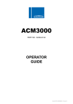
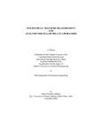
1
AC690PRO
PART NO. 02404-0116
OPERATOR
GUIDE
Document Ref: OGAC690PRO v.1.0 Aug. 2011
M2
HIGH
T2
EV3
M1
EV10
LOW
EV5
P1
T1
1
V
2
abc
EV8
EV6
EV1
3
def
4ghi
5j kl
mno
7
tuv
8
wxy z
pqrs
EV9
6
9
0
VU3
11
2
1
P
12
3
P2
M3
VU1
F1
HP
V5
V6
VU2
5
F2
4
V1 V3
EV7
10
7
6
C
9
13
8
9006359
Rel. 2
02/09
V4 V2
14
1
V
4
gh i
7
pqr s
2
abc
5
jkl
8
t uv
15 16
3
d ef
17
6
m no
9
wxy z
0
18
20
19
21
22
24
23
25
26
42
27
28
29
30
31
32
33
1
4
ghi
7
pqrs
34
35
36
2
abc
5
jkl
8
6
mno
9
tuv
wxyz
0
ENTER
MENU
37 38
3
def
41
STOP
39
40
43
44
45
_____________________________________________________________________________ AC690PRO
Dear garage owner,
Thank you for having chosen one of our instruments for your workshop. We are
certain that it will give the utmost satisfaction and be a notable help on the job.
Please become fully familiar with the instructions in this user’s manual. It should
be kept ready to hand for consultation whenever required.
AC690PRO is an electronic unit for recovery, recycle, vacuum and charge of A/C
systems using R134a as refrigerant.
A simple but reliable connection system guarantees a safe work during all of the
operations: refrigerant recovery and recycle; vacuum and leak test; additive and
lubricant injection; circuit recharge and working pressure test.
The refrigerant flow is controlled and managed by an electronic scale so as to prevent
any tank overflow or the flow of a refrigerant quantity exceeding that allowed.
The quantity to be charged in the A/C system is set by the operator by the function
keyboard or by consulting the internal database.
A patented separator still allows to separate the refrigerant from the lubricant.
OPERATING INSTRUCTIONS
45
•
It is forbidden to even partially this handbook in any way unless prior written authorisation has
been obtained from the manufacturer.
•
The data and characteristics indicated in this handbook are not binding. The manufacturer reserves
the right to make all those modifications as are considered necessary without being obliged to give
advance warning or make replacements.
•
All the names of brands and products and the trade marks are the property of the respective
owners.
TTPR – February 2009
_____________________________________________________________________________ AC690PRO
INDEX
CAPTIONS
49
GENERAL INFORMATION FOR THE USER
50
Disposing of equipment
50
Disposing of batteries
50
1.0 -
FOR A SAFE USE AC690PRO
51
1.1 -
For a safe use
51
1.2 -
Safety devices
52
1.3 -
The work environment
53
1.4 -
Tank test
53
2.0 -
INTRODUCTION TO THE UNIT
54
3.0 -
DESCRIPTION OF THE UNIT
55
3.1 -
The Keyboard
55
4.0 -
INSTALLATION OF THE UNIT
56
4.1 -
Unpacking and checking components
56
4.2 -
Machine handling and storage
56
4.3 -
Preparation for use
57
4.4 4.4.1 4.4.2 4.4.3 -
Loaded and recovered coolant storage
Report management enabling
Report printing
Report management with ACUSB (optional)
61
61
61
61
4.5 -
Bottle filling
62
4.6 -
Tank display
63
4.7 -
Oil scales reset
63
5.0 -
USE OF THE UNIT
64
5.1 -
Vehicle data entry
64
5.2 -
Database
64
5.3 -
Personalized Database
67
5.4 -
Refrigerant recovery
68
5.5 -
Evacuating the A/C system
69
5.6 -
Oil injection and A/C system charge
70
5.7 -
Automatic function
71
5.8 -
Recycling function
73
5.9 -
Incomplete charge
73
5.10 -
Flushing (optional)
74
OPERATING INSTRUCTIONS
47
AC690PRO ______________________________________________________________________________
6.0 -
DISPLAYED MESSAGES
75
6.1 -
Service messages
75
6.2 -
Error messages
75
7.0 -
MAINTENANCE
76
7.1 -
Vacuum pump oil change
76
7.2 -
Reset oil counter vacuum pump
76
7.3 -
Filter dryer change
77
7.4 -
Reset counter filter dryer
78
7.5 -
Refrigerant scale calibration
79
7.6 -
Oil replenishing scale calibration
80
7.7 -
Oil purge scale calibration
81
8.0 -
STOPPAGE FOR LONG PERIODS
82
9.0 -
DEMOLITION/DISPOSAL
82
9.1 -
Disposal of the equipment
82
9.2 -
Disposal of the recycled materials
82
10.0 -
TECHNICAL SPECIFICATIONS
83
11.0 -
SPARE PARTS
83
12.0 -
GLOSSARY OF TERMS
84
48
OPERATING INSTRUCTIONS
_____________________________________________________________________________ AC690PRO
CAPTIONS
M1
M2
M3
T1
T2
LOW
HIGH
V1
V2
V3
V4
V5
V6
VU1
VU2
VU3
F1
F2
EV1
EV3
EV5
EV6
EV7
EV8
EV9
EV10
1
2
3
4
5
6
7
8
9
10
11
12
13
P1
P2
Low pressure gauge
High pressure gauge
Inside tank pressure meter
Low pressure service hose
High pressure service hose
Manifold set low pressure valve
Manifold set high pressure valve
Tank vapour side hose valve
Tank liquid side hose valve
Tank vapour side valve
Tank liquid side valve
Safety valve
Non condensable drain valve
Oil protection unidirectional valve
Separator-still check valve
UV dye protection unidirectional valve
Recovery line mechanic filter
Dehydrating filter
Vacuum line solenoid valve
Circuit separation solenoid valve
Recovery/Recycle solenoid valve
Charge solenoid valve
Oil purge solenoid valve
Oil addition solenoid valve
UV dye injection solenoid valve
High/low pressure separation solenoid valve
Oil replenishing bottle
Vacuum pump
Pressure adjuster
Separator-still for recovered oil
Separator-still for compressor oil
Compressor
Storage tank
Electronic scale
Oil purge bottle
Heat exchanger
UV dye charge bottle
Oil replenishing scale
Oil purge scale
Pressure transducer
High pressure switch
OPERATING INSTRUCTIONS
49
AC690PRO ______________________________________________________________________________
GENERAL INFORMATION FOR THE USER
Disposing of equipment
•
Do not dispose of this equipment as miscellaneous solid municipal waste but
arrange to have collected separately.
•
The re-use or correct recycling of the electronic equipment (EEE) is important in
order to protect the environment and the wellbeing of humans.
•
In accordance with European Directive WEEE 2002/96/EC, special collection points
are available to witch to deliver waste electrical and electronic equipment.
•
The public administration and producers of electrical and electronic equipment are
involved in facilitating the processes of the re-use and recovery of waste electrical
and electronic equipment through the organisation of collection activities and the
use of appropriate planning arrangements.
•
Unauthorised disposal of waste electrical and electronic equipment is punishable by
law with appropriate penalties.
Disposing of batteries
50
•
Batteries must be recycled or disposed of properly. Do not throw batteries
away as part of normal refuse disposal.
•
Do no throw batteries into open flame!
OPERATING INSTRUCTIONS
_____________________________________________________________________________ AC690PRO
1.0 -
FOR A SAFE USE AC690PRO
The advanced technology adopted in the design and production of the AC690PRO make
this equipment extremely simple and reliable in the performance of all procedures.
Therefore, the user is not exposed to any risk if the general safety rules reported below
are followed with proper use and maintenance of the equipment.
NOTA BENE:
This unit can be exclusively used by professionally trained operators who have to know
the principles of refrigeration, refrigerating systems and gases and the possible
damages which might be caused by pressurized equipment.
Every user has to read carefully this manual for a correct and safe use of the
equipment.
1.1 -
•
For a safe use
It is necessary to wear suitable protections such as goggles and gloves, the
contact with the refrigerant can cause blindness as well as other injuries to the
operator. Please make reference to the symbols below:
Carefully read the instructions.
Do not use open air in case of rain or high humidity.
Use gloves.
Use protection goggles.
•
Avoid the contact with the skin, the low boiling temperature (about -30 °C) may
provoke freezing.
•
Do not inhale refrigerating gases fumes.
•
Before connecting the AC690PRO unit to an A/C system or to an external tank,
make sure all the valves are closed.
OPERATING INSTRUCTIONS
51
AC690PRO ______________________________________________________________________________
•
Ensure that the phase has been completed and that all valves are closed before
disconnecting the unit AC690PRO. This will prevent release of the refrigerant into
the atmosphere.
•
Do not change the safety valve or control system settings.
•
Do not use external tanks or other storage tanks that have not been
type-approved or that lack safety valves.
•
Never leave the unit live if an immediate use is not scheduled, stop the electrical
supply before a long period of unit inactivity or before internal maintenance
interventions.
•
Be careful while servicing the unit since connecting hoses may contain pressurized
refrigerant.
•
Do not use the unit in explosive environments.
Extraordinary maintenance interventions have to be performed by authorized staff only.
•
Pressure of leaks of the HCF-134a service equipment or of the air conditioning
systems of the vehicle must not be tested by using compressed air.
Some air/HCF-134a mixtures can burn at high pressures. These mixtures can be
dangerous and may cause fires or explosions and subsequent injuries or damages.
Further information on the operators’ health and safety can be obtained from the
refrigerant producers.
1.2 -
Safety devices
The AC690PRO is equipped with the following safety devices:
•
Overpressure valves.
•
Besides the overpressure valve a maximum pressure switch has been fitted
which stops the compressor in case of excessive pressure.
CAUTION:
Any type of tampering with the safety devices mentioned above is
hereby prohibited.
52
OPERATING INSTRUCTIONS
_____________________________________________________________________________ AC690PRO
1.3 -
•
The work environment
The unit has to work in a sufficiently ventilated environment.
CAUTION:
Work far from free flames and hot surfaces; at high temperatures the
refrigerant decomposes freeing toxic and aggressive substances
which are noxious for the user and the environment.
•
For a correct functioning the unit has to work on an even surface; during short
handling do not shake it.
•
Do not subject the AC690PRO unit to vibration.
CAUTION:
While operating do not disperse the refrigerant in the environment.
Such a precaution, besides being required by the international rules
for the environment protection, is necessary to prevent the possible
presence of refrigerant in the working environment from making it
difficult to detect possible leaks.
•
Work in environments with sufficient lighting.
•
Avoid inhalation of the refrigerants and oils in the A/C systems. Exposure may
cause irritation to eyes and the respiratory tract. To remove R134a from the
A/C system, use only the special recycling-units for R134a. If the refrigerant is
accidentally released into the atmosphere, ventilate the work area before resuming
service.
•
Do not use the unit under direct sunrays; sun exposure can cause excessive
temperatures and malfunctioning. Working temperatures indicated refer to the unit
being not directly exposed to the sun.
1.4 -
Tank test
The tank has to be re-tested or substituted every 10 years. Check the re-testing
date (1) written on the neck of the tank.
1
OPERATING INSTRUCTIONS
53
AC690PRO ______________________________________________________________________________
2.0 -
INTRODUCTION TO THE UNIT
The AC690PRO unit fits all of the air-conditioners functioning with R134a refrigerant
located on cars, trucks and industrial vehicles.
The AC690PRO unit microprocessor allows the managing of all functions by means of
an electronic scale, a LCD to display the weight or minute values and the help
messages of the various procedures which can be set, a control board with
alphanumeric keyboard.
By connecting the AC690PRO unit to an A/C system the refrigerating gas can be
recovered and recycled to enter the system itself again after a correct vacuum.
The amount of lubricant taken from the A/C system during the recovery can be
measured and, afterwards, reintegrated in the system.
The unit is equipped with a two-stage pump for high vacuum and a manifold set to
continuously monitor the operations in process.
Tightness test on the A/C units is carried out through the manometers the unit is
equipped with.
The unit is equipped with special connectors to avoid cross-mixing with systems using
R12.
CAUTION:
Do not try to adapt this unit for air conditioning systems using R12.
54
OPERATING INSTRUCTIONS
_____________________________________________________________________________ AC690PRO
3.0 -
DESCRIPTION OF THE UNIT
14. Keyboard.
15. Low pression gauge.
16. High pression gauge.
17. Inside tank pressure meter.
18. High pression valve.
19. Low pression valve.
20. Printer.
21. Main power switch.
22. High side connection hose.
23. Low side connection hose.
24. Oil injector glass.
25. UV dye injector glass.
26. Oil drain glass.
3.1 -
The Keyboard
27. RECOVERY function Led.
28. RECOVERY function key.
29. VACUUM function Led.
30. VACUUM function key and cursor shifting upwards.
31. CHARGE function Led.
32. CHARGE function key and cursor shifting to the right.
33. AUTOMATIC function Led.
34. AUTOMATIC function key and cursor shifting to the left.
35. FLUSHING function Led.
36. FLUSHING function key and cursor shifting downwards.
37. MENU key (menu, cancellation, by-pass and pause).
38. VEHICLE DATA and DATABASE function key.
39. Port for software updates.
40. STOP key.
41. ENTER key.
42. Display.
OPERATING INSTRUCTIONS
55
AC690PRO ______________________________________________________________________________
4.0 -
INSTALLATION OF THE UNIT
Please find below operations to perform to start the unit.
4.1 -
Unpacking and checking components
•
Remove the machine packaging.
•
Check to ensure that all of the accessory components are present:
Operating instructions.
1 Graduated beaker.
2 cylinder connectors.
Bottle safety valve conformity certificate.
4.2 -
Machine handling and storage
Remove the unit from the base pallet of the packaging.
The unit is moved on the four wheels. The two front wheels have brakes.
On rough terrain, the AC690PRO can be moved by tilting it and balancing the weight on
the two rear wheels.
In spite of the fact that the heaviest components have been assembled on the base in
order to lower the centre of gravity, it has not been possible to eliminate the
risk of overturning completely.
56
OPERATING INSTRUCTIONS
_____________________________________________________________________________ AC690PRO
4.3 -
Preparation for use
Before starting to use the AC690PRO unit, it is possible to personalize it.
These settings are not compulsory on the standard models.
To personalize the A/C unit comply with the following procedure:
•
Turn on the unit and wait until the STAND-BY page is displayed (date and time).
•
Simultaneously press the 3 and FLUSHING keys (36) for some seconds.
•
The display shows 0000.
•
Enter the code 2222.
•
A menu is displayed containing the operations that may be carried out.
•
Press the cursor shifting key upwards (30) or downwards (36) to scroll the menu.
•
Select the wished function and press ENTER to enter.
•
Press STOP to go back to the STAND-BY page.
LANGUAGE CHANGE
•
Select the LANGUAGE CHANGE function and press ENTER.
•
The list of languages available in memory is displayed.
•
Press the cursor shifting key upwards (30) or downwards (36) to scroll the menu
and press ENTER (41) to set the selected language.
•
Then the main menu is displayed again.
UNITS OF MEASURE
•
Select the UNITS OF MEASURE function and press ENTER.
•
The list of units of measure being available in memory is displayed.
•
Press either the upwards cursor shifting key (30) or the downwards cursor shifting
key (36) to scroll the menu and press ENTER (41) to set the selected unit of
measure.
•
Then the main menu is displayed again.
OPERATING INSTRUCTIONS
57
AC690PRO ______________________________________________________________________________
DATE AND TIME
•
Select the DATE AND TIME function and press ENTER.
•
The current date and time are displayed and the cursor positions on the date.
•
Enter the date and press ENTER to confirm.
•
The cursor positions on the time.
•
Enter the time and press ENTER to confirm.
•
Then the main menu is displayed again.
PIPES LENGTH
It is possible to supply, on demand, longer service pipes (optional); if this is the case it
is necessary to set the machine so that during the charge it counterbalances the
variation of coolant remaining in the pipes. The standard pipes that are supplied
standard are 2,5 m long.
•
Select the PIPES LENGTH function and press ENTER.
•
The standard length of the optional pipes is displayed.
•
Press the upwards cursor shifting key (30) or the downwards cursor shifting key
(36) to scroll the menu and press ENTER to set the selected length.
•
Then the main menu is displayed again.
GARAGE DATA
To enter the workshop data there are 8 lines of 20 characters each.
The data entering is carried out through the keyboard, in a way similar to that used for
mobile phones:
•
Select the GARAGE DATA function and press ENTER.
•
Press the numerical keys to select the letters and the characters.
•
Press the cursor shifting keys to shift among the lines.
•
Press the MENU key (37) to erase the character that precedes the cursor.
•
Press ENTER to memorize the garage data entry.
•
Then the main menu is displayed again.
58
OPERATING INSTRUCTIONS
_____________________________________________________________________________ AC690PRO
CONTRAST
•
Select the CONTRAST function and press ENTER.
•
A numerical index of the contrast degree is displayed.
•
Press the upwards cursor shifting key (30) or the downwards cursor shifting key
(36) to modify the contrast and press ENTER to confirm.
•
Then the main menu is displayed again.
FLUSHING
It is possible to install on the A/C unit the optional kit for the flushing of components.
If the unit is equipped with this kit, it is necessary to insert it in the internal parameters
so that it enables the function.
•
Select the FLUSHING function and press ENTER.
•
The display displays the messages ENABLED and DISABLED.
•
Press the upwards cursor shifting key (30) or the downwards cursor shifting key
(36) to select either ENABLED or DISABLED and press ENTER to confirm.
•
Then the main menu is displayed again.
OIL SCALES
In case of malfunction the oil refilling and discharge scales can be disabled to prevent
the station stop.
•
Select the OIL SCALES function and press ENTER.
•
The display displays the messages ENABLED and DISABLED.
•
Press the upwards cursor shifting key (30) or the downwards cursor shifting key
(36) to select either ENABLED or DISABLED and press ENTER to confirm.
•
Then the main menu is displayed again.
OPERATING INSTRUCTIONS
59
AC690PRO ______________________________________________________________________________
UV DYE
This menu is used to display the request of dye injection before the charge.
•
Select the UV DYE function and press ENTER.
•
The display displays the messages ENABLED and DISABLED.
•
Press the upwards cursor shifting key (30) or the downwards cursor shifting key
(36) to select either ENABLED or DISABLED and press ENTER to confirm.
•
Then the main menu is displayed again.
CAUTION:
To avoid any problems due to chemical incompatibilities with the
internal components of the service station, use only UV dyes selected
and supplied by Robinair under the following part numbers: RA16356,
RA16357 or RA16286B. Problems resulting from the use of any
different types of dyes, will cancel the unit warranty.
DATABASE UPDATE
This menu is used to update the car manufacturers’ database.
•
Insert the update key into the board front side.
•
Select the DB UPDATE function and press ENTER
•
At the end of the operation the board resets automatically.
•
Extract the key.
NOTA BENE:
Do not switch off the A/C unit during the updating.
ENTRY OF THE SERIAL NUMBER
•
Select the SERIAL NUMBER function and press ENTER.
•
Enter the station serial number (engraved on the technical data plate applied to
the station rear panel) by the numerical keys and then press ENTER.
•
Then the main menu is displayed again.
NOTA BENE:
Only the last 5 digits of the number have to be entered since the first one is entered
automatically by the program.
60
OPERATING INSTRUCTIONS
_____________________________________________________________________________ AC690PRO
4.4 -
Loaded and recovered coolant storage
If you want to storage and then print the data of the loaded and recovered coolant you
have to enable the “Report Management” function. Once all data of the loaded and
recovered coolant are enabled they are automatically stored.
4.4.1 -
Report management enabling
To enable the report management proceed as follows:
•
Simultaneously press the 3 and FLUSHING keys for some seconds.
•
The displays shows 0000.
•
Set the value 5599.
•
The functions menu is displayed.
•
Press the upwards cursor shifting key (30) or the downwards cursor shifting key
(36) to select either REPORT MANAGEMENT and press ENTER to confirm.
•
Select ENABLE and press ENTER.
4.4.2 -
Report printing
CAUTION:
The station has a big memory that is able to contain more data than
those you can print on a 12m long roll of paper.
To print the stored data proceed as follows:
•
Press the MENU key from the STAND-BY page.
•
The functions menu is displayed.
•
Press the upwards cursor shifting key (30) or the downwards cursor shifting key
(36) to select either REPORT MANAGEMENT and press ENTER to confirm.
•
Select the PRINT REPORT function and press ENTER.
•
The display shows the stored records quantity.
•
Press the ENTER key to print. Afterwards any record can be deleted.
Before printing, be sure to have enough paper. It is recommended to print the stored
records at least once a week in order to avoid a too long print which would also be
difficult to consult.
Delete the already printed records so that they will not be accumulated with those
stored afterwards (otherwise they would be printed again in a new print).
4.4.3 -
Report management with ACUSB (optional)
The stored records can be downloaded to a PC by means of the ACUSB reader.
To transfer data on the PC, please refer to the ACUSB reader’s operating manual.
OPERATING INSTRUCTIONS
61
AC690PRO ______________________________________________________________________________
4.5 -
Bottle filling
Before being able to use the unit, after personalizing it, it is necessary to inject some
coolant in the inner bottle. Comply with the following procedure:
•
Connect the service pipe
(use the supplied unions).
to
an
external
container
full
of
coolant
NOTA BENE:
There are two types of source tanks: one with a liquid outlet and one without.
Tanks with liquid outlets must remain in an upright position in order to transfer the
liquid refrigerant. Use the LIQUID valve connection for this type of tank.
Tanks without liquid outlets are usually equipped with only one valve and have to be
overturned to transfer the liquid refrigerant.
•
Open the valve on the external bottle and on the service pipe.
•
Open the high and low pressure valves on the unit.
•
Press the MENU key (37) from the STAND-BY page.
•
The functions menu is displayed.
•
Press the upwards cursor shifting key (30) or the downwards cursor shifting key
(36) to select the BOTTLE FILLING and press ENTER to confirm.
•
The display shows the tank available capacity.
•
Set the amount of coolant that you wish to inject (it is advisable to inject at
least 4-5 kg).
•
Press ENTER to start the operation.
•
Some massages prompt the operator for the pipes connection, then the function
starts.
•
The unit automatically stops once reached the set value.
•
Close the valve on the source tank.
•
Press ENTER to complete the operation and empty the pipes and the still
separator.
NOTA BENE:
Usually the final amount of recovered coolant exceeds the set value by about
500-700 g, since also the still separator is emptied.
•
The function stops automatically when pressure is over in the system.
•
The STAND-BY page is displayed.
•
Close the valves on the unit.
62
OPERATING INSTRUCTIONS
_____________________________________________________________________________ AC690PRO
4.6 -
Tank display
From the STAND-BY page it is possible to display the weight of the coolant in the tank.
•
Press ENTER to display the weight.
•
Press STOP to go back to the STAND-BY page.
4.7 -
Oil scales reset
NOTA BENE:
It is advisable to carry out this operation at regular intervals since it is useful to correct
the zero point deviation of the oil loading cells (this operation is similar to that carried
out for the kitchen scales). Should this operation not be carried out, the unit operation
is not compromised since the software works only by weights difference.
•
Press the MENU key from the STAND-BY page.
•
Press the upwards cursor shifting key (30) or the downwards cursor shifting key
(36) to select the SCALES RESET and press ENTER to confirm.
•
The display requires the oil bottle disconnection.
•
Press the ENTER key to continue.
•
The display waits for some seconds before carrying out the automatic reset.
•
At the end of the reset the display requires the oil bottle reconnection.
•
Press ENTER to go back to the STAND-BY page.
OPERATING INSTRUCTIONS
63
AC690PRO ______________________________________________________________________________
5.0 -
USE OF THE UNIT
Find below the description of the unit functions.
5.1 -
Vehicle data entry
This function enables the display of the vehicle data into the print-out.
•
Press the VEHICLE DATA key (38).
•
Press the upwards cursor shifting key (30) or the downwards cursor shifting key
(36) to select either VEHICLE DATA and press ENTER (41) to confirm.
•
Enter the vehicle data with the alphanumeric keyboard.
•
Press the MENU key (37) to erase the character that precedes the cursor.
•
Press ENTER to confirm the entered datum and shift to the next line.
•
Repeat the data entry and confirmation operation for all the items; in the end the
main menu will be displayed again.
5.2 -
Database
Charge data can be taken directly from the internal database. The database also
contains further pieces of information that may be displayed or printed.
•
Press the DATABASE key (38).
•
Press the upwards cursor shifting key (30) or the downwards cursor shifting key
(36) to select either DATABASE and press ENTER to confirm.
•
By the alphanumerical keys select the first letter of the car’s make. Use the cursor
keys to select the make of the tested car and press ENTER to confirm.
•
By the alphanumerical keys select the first letter of the car’s model. Use the
cursor keys to select the model of the tested car and press ENTER to confirm.
•
After scrolling all data the display shows two selection options:
Digit 1 to store data and use them during the next service. Then the program
displays the STAND-BY page again.
Digit 2 to display data. Use the cursor shifting keys to scroll the data
concerning the vehicle.
Press the ENTER key to print.
Press STOP (40) to go back to the DATABASE menu.
64
OPERATING INSTRUCTIONS
_____________________________________________________________________________ AC690PRO
DIAGNOSIS
It is important to note that the vehicle to be tested should be in a place that is not in
direct sunlight and away from any adverse wind/drafty conditions. The most
insignificant air currents can falsify the performance values drastically.
To evaluate the air conditioning system it is important to follow the procedure below:
•
LOWER Bonnet.
•
START engine (engine to be at normal operating temperature).
•
Stabilise engine rpm at approximately 1500-2000 rpm.
•
Air conditioning system ON.
•
Centre face vent OPEN.
•
Heating setting to maximum COLD.
•
Interior fan set to HIGH.
•
Recirculation OFF.
•
Doors and windows OPEN.
It is recommended to confirm the compressor clutch is engaged before carrying out any
performance tests.
Before recording or inputting any data it is important to note the position of the HVAC
controls, engine temperature / rpm and adequate time has been given to allow the a/c
system to Stabilise (no less than 3 minutes).
Ambient Temperature - To record the ambient temperature, it is important to take
the temperature of the ambient air at approximately 1metre in front of the car.
Inputting the temperature of the air around the engine compartment may lead to
incorrect diagnosis.
High Side Pressure – With the compressor clutch engaged record the highest high
pressure gauge reading. It is important to note a cycling clutch system will cause the
compressor to cut in and out, thus, the high side pressure will rise and fall. It is the
highest pressure reading that should be recorded.
Low Side Pressure - With the compressor clutch engaged record the lowest low
pressure gauge reading. It is important to note a cycling clutch system will cause the
compressor to cut in and out, thus, the low side pressure will rise and fall. It is the
lowest pressure reading that should be recorded.
Centre Vent Temperature – When taking the centre face vent temperature input a
mean value.
OPERATING INSTRUCTIONS
65
AC690PRO ______________________________________________________________________________
CAUTION:
Air conditioning diagnostic software is designed to assist and guide
professional
and
competent
technicians
diagnose
air
conditioning/climate control faults. The diagnosis and rectification
offered is to be used for guidance purposes only and in no way should
result in the replacing of components without first being inspected by
the technician and established to be faulty.
•
Press the MENU key from the STAND-BY page.
•
Press the upwards cursor shifting key (30) or the downwards cursor shifting key
(36) to select the DIAGNOSIS and press ENTER to confirm.
NOTA BENE:
Diagnostics function only work if a vehicle from the database is selected. Otherwise the
program enters directly the database enabling the selection and memorization of a
vehicle before moving to the diagnostics.
•
Entered the ambient temperature measured value and press ENTER.
•
Entered the high pressure measured value and press ENTER.
•
Entered the low pressure measured value and press ENTER.
•
Entered the flap air temperature measured value and press ENTER.
•
The display shows two selection options:
Digit 1 to select the result and display entered data with their status: OK, high,
low.
Press the ENTER key to print.
Digit 2 to select hints and display the list of possible causes of the defect and
the operation to carry out to solve the problem.
Press the ENTER key to print.
•
66
Press STOP to go back to the STAND-BY page. When quitting, the program asks
whether to cancel the vehicle data set in memory or not.
OPERATING INSTRUCTIONS
_____________________________________________________________________________ AC690PRO
5.3 -
Personalized Database
It is possible to create a personalized database where you can enter the data of the
new vehicles that are not present in the database standard.
•
Press the DATABASE key (38).
•
Press the upwards cursor shifting key (30) or the downwards cursor shifting key
(36) to select either PERSONALIZED DATABASE and press ENTER to confirm.
•
Enter the required data through the alphanumeric keyboard.
NOTA BENE:
Four lines of 20 characters each are available for the description of the car. We suggest
entering Make, Model, etc. since descriptions are entered in alphabetical order.
The following lines are available: one 20 character line for the coolant amount, one
20 character line for the type of oil and one 20 character line for the amount of oil.
•
Press the MENU key to erase the character that precedes the cursor.
•
Press the cursor shifting keys to shift the cursor on the display.
•
Press ENTER to confirm the entered datum and shift to the next line.
NOTA BENE:
If necessary, it is possible to avoid entering all of the required data; if this is the case,
press ENTER to shift to the next line and the field relating to that specific datum will
not be filled in.
•
Repeat the data entry and confirmation operation for all the items; in the end the
main menu will be displayed again.
OPERATING INSTRUCTIONS
67
AC690PRO ______________________________________________________________________________
5.4 -
Refrigerant recovery
CAUTION:
Always wear protection goggles and gloves when working with
refrigerant. Read and comply with warnings at the beginning of this
manual before using the unit.
NOTA BENE:
Run the A/C system for some minutes before starting recovery. Tests proved that a
bigger amount of refrigerant is sucked if this operation is performed. Turn off the
A/C system before servicing.
In order to recover the coolant present in the A/C system, carry out the following
procedure:
•
Some messages prompt the operator for the pipes connection. Press ENTER to go
to the next message.
•
Connect the T1 low pressure and T2 high pressure hoses of the A/C system.
•
Open the valves on the hose quick couplers T1 and T2.
•
Open the high and low pressure valves on the unit.
•
Press the RECOVERY key (28), and the self-cleaning function is started.
•
The function is not started in case of lack of pressure in the system; in this case a
message is displayed to inform the operator.
NOTA BENE:
This function is useful to ensure a correct weighing of the recovered coolant.
The self-cleaning function can be passed by pressing the MENU key.
•
When the self-cleaning is over, the refrigerant recovery starts.
NOTA BENE:
The function stops automatically when the pressure inside the system drops below
0 bar.
•
At the end of recovery the oil is automatically drained and the pressure values are
checked.
•
The scale located on the oil bottle stores the weight of the discharged oil.
•
When the waiting time is over:
The function restarts automatically, if pressure has increased.
The display shows the amount of recovered coolant and oil if the pressure was
stable.
•
Close the valves on the unit.
68
OPERATING INSTRUCTIONS
_____________________________________________________________________________ AC690PRO
•
Press the ENTER key to print.
•
Press STOP to go back to the STAND-BY page. When quitting, the program asks
whether to cancel the vehicle data set in memory or not.
•
Some messages prompt the operator for the pipes disconnection.
•
Select the wished option.
5.5 -
Evacuating the A/C system
NOTA BENE:
If the vacuum pump has run for more than 10 hours the message CHANGE OIL
appears. Carry out the maintenance according to the procedures described in the
relevant section.
•
Some messages prompt the operator for the pipes connection. Press ENTER to go
to the next message.
•
Open the high and low pressure valves on the unit.
•
Press the VACUUM key (30).
•
The function is not started in case of pressure presence in the system; in this case
a message is displayed to inform the operator.
•
Enter the wished vacuum time.
•
Press ENTER to confirm and start the function.
•
When the vacuum time is over the pressure values check time starts. At the end of
this time the check result is displayed showing whether leaks have been detected
on the system.
•
Close the valves on the unit.
•
Press the ENTER key to print.
•
Press STOP to go back to the STAND-BY page. When quitting, the program asks
whether to cancel the vehicle data set in memory or not.
•
Some messages prompt the operator for the pipes disconnection.
•
Select the wished option.
OPERATING INSTRUCTIONS
69
AC690PRO ______________________________________________________________________________
5.6 -
Oil injection and A/C system charge
CAUTION:
This function must be performed only on A/C systems under vacuum
(following a system evacuation function). At the end of the oil
injection function, following a filling function.
Charge the oil from the high side only. In case of systems equipped
with low side fitting only (LOW), wait at least 10 minutes before
starting the A/C system after the charge.
•
Some messages prompt the operator for the pipes connection. Press ENTER to go
to the next message.
•
Check that the service pipes are connected and that their valves are open.
•
Press the CHARGE key (32).
•
The UV dye injection request is displayed.
Digit 1 to inject the UV dye.
Digit 2 not to inject the UV dye.
•
The display requires whether to carry out the oil charge.
Digit 1 to charge oil. Select the amount of oil to be charged by means of
numerical keys (the display shows by default the value of the discharged oil)
and use the MENU key to change the default value; press ENTER to confirm.
Digit 2 to avoid oil injection.
•
The display requires the entry of the amount of refrigerant to be charged.
NOTA BENE:
If cars are selected through the Database, the display shows automatically the amount
of coolant to be charged for the selected car.
•
Enter the amount of refrigerant to be charged and press ENTER to confirm.
•
The station carries out all operations in sequence and in the end it displays the
coolant and charged oil value.
•
To verify if the circuit is efficient, you need to check the functioning pressures.
•
Close the valves on the unit.
CAUTION:
Failure to close the valves may cause errors, malfunction or damage
of the internal components.
•
Switch On the car and the A/C system.
•
Check pressure values.
•
Switch Off the A/C system and the car.
70
OPERATING INSTRUCTIONS
_____________________________________________________________________________ AC690PRO
•
Close the valves on the service pipes.
•
Press the ENTER key to print.
•
Press STOP to go back to the STAND-BY page. When quitting, the program asks
whether to cancel the vehicle data set in memory or not.
•
Some messages prompt the operator for the pipes disconnection.
•
Select the wished option.
5.7 -
Automatic function
This function allows carrying out recovery, vacuum, and charge functions in automatic
function.
CAUTION:
For cars equipped with a single service fitting the charge function
should be carried out manually by following the procedure suggested
by the manufacturer.
To carry out the automatic function:
•
Some messages prompt the operator for the pipes connection. Press ENTER to go
to the next message.
•
Connect the T1 low pressure and T2 high pressure hoses of the A/C system.
•
Open the valves on the hose quick couplers T1 and T2.
•
Open the high and low pressure valves on the unit.
•
Press the AUTOMATIC function key (34).
•
The display requires the entry of the vacuum time.
•
Enter the value and press ENTER to confirm.
•
The UV dye injection request is displayed.
Digit 1 to inject the UV dye.
Digit 2 not to inject the UV dye.
•
The display requires whether to carry out the oil charge.
Digit 1 to confirm. A message on the display asks whether some more oil has
to be added to the amount recovered. Select the amount of oil by the
numerical keys and press ENTER to confirm.
Digit 2 to avoid oil injection.
•
The display requires the entry of the amount of refrigerant to be charged.
OPERATING INSTRUCTIONS
71
AC690PRO ______________________________________________________________________________
NOTA BENE:
If cars are selected through the Database, the display shows automatically the amount
of coolant to be charged for the selected car.
•
Enter the amount of refrigerant to be charged and press ENTER to confirm.
•
The function starts and continues automatically til the end.
NOTA BENE:
In case of errors, the station stops and displays the relevant error message.
•
To verify if the circuit is efficient, you need to check the functioning pressures.
•
Close the valves on the unit.
CAUTION:
Failure to close the valves may cause errors, malfunction or damage
of the internal components.
•
Switch On the car and the A/C system.
•
Check pressure values.
•
Switch Off the A/C system and the car.
•
Close the valves on the unit.
•
Press the ENTER key to print.
•
Press STOP to go back to the STAND-BY page. When quitting, the program asks
whether to cancel the vehicle data set in memory or not.
•
Some messages prompt the operator for the pipes disconnection.
•
Select the wished option.
72
OPERATING INSTRUCTIONS
_____________________________________________________________________________ AC690PRO
5.8 -
Recycling function
•
Press the MENU key from the STAND-BY page.
•
Press the upwards cursor shifting key (30) or the downwards cursor shifting key
(36) to select either RECYCLING and press ENTER to confirm.
•
The function is self-limited to 60 minutes.
•
Press STOP to stop the function.
•
The function stops automatically after the complete draining of the internal circuit.
5.9 -
Incomplete charge
•
Close the high side quick coupler valve on the T2 service hose on the A/C system.
•
Start the vehicle system.
•
Open the high and low pressure valves on the unit.
•
Press ENTER to complete the charge.
•
Let the residual refrigerant be sucked until manifold gauges show a pressure of
about 1-2 bar.
•
Close the low side quick coupler valve on the T1 service hose on the A/C system.
•
Turn off the vehicle and disconnect the unit from the vehicle.
•
Close the valves on the unit.
CAUTION:
Disconnect the flexible hoses with extreme caution. All of the flexible
hoses can contain liquid refrigerant under pressure. Before using the
equipment read and follow carefully the instructions at the beginning
of this manual.
OPERATING INSTRUCTIONS
73
AC690PRO ______________________________________________________________________________
5.10 -
Flushing (optional)
NOTA BENE:
Carefully read the flushing kit instructions for the correct connection and use of
accessories.
To use the flushing kit follow instructions below:
•
Connect the flushing kit and the part to be flushed following instructions of the
flushing kit manual.
•
Open the low side valve and press ENTER to continue.
•
Select the vacuum time and press ENTER to drain the component.
•
After the vacuum phase a test is carried out to be sure of the absence of leaks.
•
If the leak test is positive, open the flushing valve.
•
Wait until the flushing time is over or, if the cleaning is correct, press the MENU
key.
•
Close the flushing valve and press ENTER to drain the circuit.
•
Press ENTER to print the flushing report.
•
Press STOP to terminate.
74
OPERATING INSTRUCTIONS
_____________________________________________________________________________ AC690PRO
6.0 -
DISPLAYED MESSAGES
6.1 -
Service messages
CHANGE OIL
Vacuum pump oil change (see chapter 7.1).
CHANGE FILTER
Change filter dryer (see chapter 7.3).
6.2 -
Error messages
HIGH PRESSURE
Out feed pressure from compressor is excessively high. Switch off the unit and wait for
about 30 minutes. If the problem persists, apply to the Technical Service.
SOFTWARE ERROR
Error in the software, apply to the Technical Service.
FULL BOTTLE
Coolant level in the bottle reached the maximum capacity level, carry out some charges
to reduce the amount of coolant inside.
SCALE RECALIBRATION
Error in scale calibration, reset it. If the error persists, apply to the Technical Service.
HIGH RECOVERY TIME
The recovery time exceeds the set safety limit. Make sure there are no leaks in the A/C
system. If no leaks are detected, apply to the Technical Service.
EMPTY SYSTEM
There is no refrigerant in the A/C system.
BOWL FULL
The oil discharge bowl is full and has to be drained.
BOWL EMPTY
The oil injection bowl is empty and has to be charged.
FULL SYSTEM
The A/C system is charged with refrigerant.
INCOMPLETE CHARGE
Excessive charge time; this proves that the pressure inside the bottle is equal to the
pressure inside the A/C system (see chapter 5.9).
OIL CHARGE TIME HIGH
The A/C system is not under vacuum and the station cannot suck oil.
OPERATING INSTRUCTIONS
75
AC690PRO ______________________________________________________________________________
7.0 -
MAINTENANCE
The AC690PRO is a highly reliable unit built with top-quality components with the use of
today's most advanced production techniques.
For these reasons, maintenance is reduced to a minimum and marked by a very low
frequency of intervention. In addition, owing to the electronic control system, all
periodic maintenance procedures are signalled at the prescribed time.
CHANGE OIL
Change vacuum pump oil (10 hours).
CHANGE FILTER
Change filter dryer (150 kg of fluid).
7.1 -
Vacuum pump oil change
The oil of the vacuum pump must be changed frequently in order to assure higher
performances of the unit.
When the oil has to be changed, the display shows CHANGE OIL.
To change the oil, follow carefully these instructions:
•
Disconnect the unit from the power supply.
•
Put a beaker under the cap (45), open the cap and discharge the oil contained in
the vacuum pump.
•
When the pump is empty, screw in the cap (45) and open the upper cap (43).
•
Fill the pump with the oil through the upper hole. Check the oil level in the pump
through the inspection glass (44); level has to reach the sight glass middle line.
•
When the pump is filled, close the upper cap.
7.2 -
Reset oil counter vacuum pump
After having changed the oil of the vacuum pump, reset the counter.
To reset the counter follow carefully these instructions:
•
Simultaneously press the 3 and FLUSHING keys for some seconds.
•
The display shows the message 0000.
•
Digit 5555 on the keypad and press ENTER.
•
The functions menu is displayed.
•
Press the upwards cursor shifting key (30) or the downwards cursor shifting key
(36) to select either OIL CHANGE and press ENTER to confirm.
76
OPERATING INSTRUCTIONS
_____________________________________________________________________________ AC690PRO
The display shows a value which corresponds to the working hours of the vacuum
pump.
•
Press the MENU key and keep it pressed.
•
When the display shows 0000 release the MENU key.
•
The display displays the functions menu again.
•
Press STOP to go back to the STAND-BY page.
7.3 -
Filter dryer change
The filter dryer of this unit has been designed in order to eliminate all acid residues and
the high water content of the refrigerant R134a.
The filter has to be changed when the display shows the message CHANGE FILTER.
To change correctly the filter dryer, follow carefully these instructions.
•
Connect the unit to the electrical power supplied and press the RECOVERY key.
•
Open the high and low pressure valves on the unit.
•
Wait for the end of self-cleaning.
•
Let the compressor operate until the pressure indicated on the manometers has
not decreased under the 0 (zero) bar value.
•
Press the STOP key to stop the compressor. Now all the refrigerant has been
drained from the filter and no pressure should be present.
•
Close the valves on the unit.
•
Disconnect the unit from the electrical power supply and remove the lower front
panel.
CAUTION:
During the following phase it will be necessary to open the refrigerant
circuit of the unit. Wear goggles and gloves.
•
Disconnect the filter with caution and replace it with a new one.
CAUTION:
Check that the sealing rings are in the right position.
•
Set up the plastic protection again.
OPERATING INSTRUCTIONS
77
AC690PRO ______________________________________________________________________________
7.4 -
Reset counter filter dryer
After the change of the filter dryer, reset the counter.
To reset the counter follow carefully these instructions:
•
Simultaneously press the 3 and FLUSHING keys for some seconds.
•
The display shows the message 0000.
•
Digit 5555 on the keypad and press ENTER.
•
The functions menu is displayed.
•
Press the upwards cursor shifting key (30) or the downwards cursor shifting key
(36) to select either FILTER CHANGE and press ENTER to confirm.
The display displays a value, either in kg or in Pounds, corresponding to the amount of
coolant that has been filtered.
•
Press the MENU key and keep it pressed.
•
When the display shows 0000 release the MENU key.
•
The display displays the functions menu again.
•
Press STOP to go back to the STAND-BY page.
78
OPERATING INSTRUCTIONS
_____________________________________________________________________________ AC690PRO
7.5 -
Refrigerant scale calibration
Required equipment:
2 Sample weights.
After removing the rear cover, remove the container to the scale plate.
NOTA BENE:
The hoses from the internal container do not have to be disconnected. If you wish to
disconnect them, close the valves on the pipes and on the bottle.
•
Simultaneously press the 3 and FLUSHING keys for some seconds.
•
The displays shows 0000.
•
Set the value 1111.
•
Press the ENTER key.
•
The functions menu is displayed.
•
Press the upwards cursor shifting key (30) or the downwards cursor shifting key
(36) to select either BOTTLE CALIBRATION and press ENTER to confirm.
•
The displays shows ZERO WEIGHT.
•
With the scale pan being completely empty, insert the numerical value 00.00 and
press the ENTER key.
•
The displays shows SAMPLE WEIGHT.
•
Position the sample weight on the scale plate (the suggested weight ranges
between 10 and 15 kg).
•
Enter the sample weight value and press the ENTER key.
•
The display displays the functions menu again.
•
Press STOP to go back to the STAND-BY page.
OPERATING INSTRUCTIONS
79
AC690PRO ______________________________________________________________________________
7.6 -
Oil replenishing scale calibration
Required equipment:
2 Sample weights.
•
Simultaneously press the 3 and FLUSHING keys for some seconds.
•
The displays shows 0000.
•
Set the value 1111.
•
Press the ENTER key.
•
The functions menu is displayed.
•
Press the upwards cursor shifting key (30) or the downwards cursor shifting key
(36) to select either IN OIL CALIBRATION and press ENTER to confirm.
•
The displays shows ZERO WEIGHT.
•
With the scale pan being completely empty (bowl disconnected), insert the
numerical value 00.00 and press the ENTER key.
•
The displays shows SAMPLE WEIGHT.
•
Position the sample weight on the scale plate (the suggested weight ranges
between 200 and 1000 g).
NOTA BENE:
It is possible to weigh one of the bottles containing the oil and use it as sample weight.
•
Enter the sample weight value and press the ENTER key.
•
The display displays the functions menu again.
•
Press STOP to go back to the STAND-BY page.
80
OPERATING INSTRUCTIONS
_____________________________________________________________________________ AC690PRO
7.7 -
Oil purge scale calibration
Required equipment:
2 Sample weights.
•
Simultaneously press the 3 and FLUSHING keys for some seconds.
•
The displays shows 0000.
•
Set the value 1111.
•
Press the ENTER key.
•
The functions menu is displayed.
•
Press the upwards cursor shifting key (30) or the downwards cursor shifting key
(36) to select either OUT OIL CALIBRATION and press ENTER to confirm.
•
The displays shows ZERO WEIGHT.
•
With the scale pan being completely empty (bowl disconnected), insert the
numerical value 00.00 and press the ENTER key.
•
The displays shows SAMPLE WEIGHT.
•
Position the sample weight on the scale plate (the suggested weight ranges
between 200 and 1000 g).
NOTA BENE:
It is possible to weigh one of the bottles containing the oil and use it as sample weight.
•
Enter the sample weight value and press the ENTER key.
•
The display displays the functions menu again.
•
Press STOP to go back to the STAND-BY page.
OPERATING INSTRUCTIONS
81
AC690PRO ______________________________________________________________________________
8.0 -
STOPPAGE FOR LONG PERIODS
•
The unit must be kept in a safe place
•
Ensure that the valves on the internal tank are closed.
•
To resume use, follow the activation process only after reopening the internal tank
valves.
9.0 -
DEMOLITION/DISPOSAL
9.1 -
Disposal of the equipment
At the end of the equipment's lifetime, the following procedures must be performed:
•
Detach and vent the gas from the unit circuit: be sure the refrigerant tank too is
completely discharged, in compliance with the rules in force.
•
Deliver the unit to a disposal center.
9.2 -
Disposal of the recycled materials
•
The refrigerants recovered from A/C systems and which cannot be reused, must be
delivered to gas suppliers for disposal as required.
•
The lubricants extracted from systems must be delivered to used oil collection
centres.
82
OPERATING INSTRUCTIONS
_____________________________________________________________________________ AC690PRO
10.0 -
TECHNICAL SPECIFICATIONS
Refrigerant:
R134
Coolant electronic scale resolution:
±5g
M1 M2 gauges:
Kl. 1.0
M3 gauge:
Kl. 2.5
Container capacity:
27 l
Maximum weight that can be stored:
20 kg
Filtering station:
1 spin-on filter dryer
Supply voltage:
230 V/50 Hz
Power:
800 W
Working temperature:
10°C ÷ + 50°C
Humidity: 20 ÷ 75%
Transport and storage temperature:
- 25°C ÷ + 60°C
Dimensions:
1270 × 690 × 660
Weight:
110 kg approx with empty tank
Noise:
<70 dB (A)
11.0 -
SPARE PARTS
Components indicated below are those necessary for routine maintenance.
Dehydrating filter
N°1 Vacuum pump oil bottle
Thermal paper roller
OPERATING INSTRUCTIONS
5117399
RA13119B
5607069
83
AC690PRO ______________________________________________________________________________
12.0 -
GLOSSARY OF TERMS
•
Refrigerant: A refrigerant solely of the type for which the unit has been created
(ex. R134a).
•
A/C system: Air-conditioning system in the motor vehicle.
•
Unit or Station: AC690PRO equipment for the recovery, recycling, evacuation
and filling of the A/C system.
•
External tank: Non-refillable fresh refrigerant (ex. R134a) cylinder, used to fill
the refrigerant tank.
•
Refrigerant tank: The tank specifically designed for the unit.
•
Function: Execution of an individual function.
•
Recovery/Recycling: Function in which the refrigerant is recovered by an
A/C system and stored in the internal container.
•
Evacuation: Function in which incondensables and moisture are evacuated from
an A/C system solely by means of a vacuum pump.
•
Oil injection: Introduction of oil inside an A/C system for the purpose of
maintaining the amount of oil specified by the manufacturer.
•
Filling: Function during which refrigerant is introduced into an A/C system in the
amount specified by the manufacturer.
84
OPERATING INSTRUCTIONS