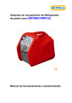
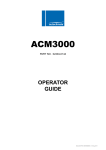
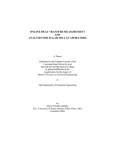
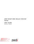
1
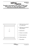
Automatic equipment for recovery,
vacuum and refilling of air
conditioning systems
MODEL: AT41502
SERVICE MANUAL
UNIT AT41502
1
1.1
1.2
1.3
1.4
1.5
1.6
2
3
3.1
3.2
3.3
3.4
3.5
3.6
3.7
4
4.1
4.2
4.3
SERVICE MANUAL .............................................................................................................. 2
SERVICE MENU ACCESS PROCEDURE .......................................................................... 2
REFRIGERANT WEIGHING SCALES CALIBRATION................................................... 3
RESET MAINTENANCE COUNTER TO REPLACE PUMP OIL/FILTER..................... 4
HISTORICAL MAINTENANCE COUNTERS .................................................................... 5
OPERATION PARAMETERS SETTINGS .......................................................................... 6
HOSES LENGTH ADAPTER PARAMETER ...................................................................... 8
ENTERING DEFAULT PARAMETERS ............................................................................. 9
VIEW OF COMPONENTS .................................................................................................. 10
GENERAL VIEW .................................................................................................................. 10
CONTROL PANEL ............................................................................................................... 11
SUCTION UNIT .................................................................................................................... 12
VALVE UNIT ........................................................................................................................ 13
REFRIGERANT CONTAINER SAFETY VALVE............................................................ 14
WEIGHING SCALES............................................................................................................ 14
LOGIC/POWER BOARD ..................................................................................................... 15
FLOW DIAGRAM ................................................................................................................ 16
TABLE OF COMPONENTS ................................................................................................ 16
ELECTRIC DIAGRAM......................................................................................................... 17
TABLE OF CONNECTIONS ............................................................................................... 17
SERVICE MANUAL AT41502
Page 1 of 18
UNIT AT41502
1 SERVICE MANUAL
1.1 SERVICE MENU ACCESS PROCEDURE
WARNING: PERFORM THIS PROCEDURE ONLY AFTER HAVING READ THE
FOLLOWING INSTRUCTIONS CAREFULLY. IF NOT PERFORMED PROPERLY, THIS
PROCEDURE CAN CAUSE MALFUNCTIONING AND DAMAGE THE UNIT.
Connect the power supply to the unit.
Proceed as follows when the display shows the net weight available (Stand-by
mode):
Press the UP Key and hold down.
Press the START/STOP Key and hold down.
Release the UP Key.
Press the DOWN Key and hold down.
Release the START/STOP Key.
Release the DOWN Key.
The display shows 0000.
Use the UP-DOWN Keys to access the following menus:
1
6
883
567
32
Refrigerant weighing scales calibration
Calibration (reset) maintenance counter for pump/filter oil replacement
Historical maintenance counters
Operation parameters settings
Hoses length adapter parameter
Set the desired menu.
Use the START/STOP Key to confirm.
See the chapters on the individual menus.
SERVICE MANUAL AT41502
Page 2 of 18
UNIT AT41502
1.2 REFRIGERANT WEIGHING SCALES CALIBRATION
Required equipment:
1 Cross-head screwdriver PH 2
1 Hexagonal spanner 10 mm
1 Sample weight min. 10 kg
Remove the M6 screw that fastens the container (34) to the weighing scales pan
(18). Remove the container (34).
Set menu 1 (see Section 1.1), confirm with the START/STOP Key.
The display shows t0 FL.
With the weighing scales pan (18) completely empty, press the START/STOP Key.
The display shows tF FL.
Place the sample weight on the weighing scales pan (18), for example 10 kg.
Confirm with the START/STOP Key.
The display shows the theoretical weight read by the weighing scales.
Use the UP-DOWN Keys to set the sample weight value.
Confirm with the START/STOP Key.
The display shows –End–.
Press the START/STOP Key to exit.
The display shows the Stand-by mode.
• If the calibration procedure is unsuccessful or the display shows the message Err, enter the default
parameters again. Afterwards, calibrate the refrigerant weighing scales once again.
SERVICE MANUAL AT41502
Page 3 of 18
UNIT AT41502
1.3 RESET MAINTENANCE COUNTER TO REPLACE PUMP OIL/FILTER
Set menu 6 (see Section 1.1), confirm with the START/STOP Key.
The display shows cnt P.
Press the START/STOP Key.
The display shows the work time (max. time 3,600 minutes).
Press the F Key and hold down.
The display shows cont – rESEt alternately.
When the display shows 0, release the F Key.
Press the START/STOP Key to exit.
The display shows the Stand by mode.
SERVICE MANUAL AT41502
Page 4 of 18
UNIT AT41502
1.4 HISTORICAL MAINTENANCE COUNTERS
Set the menu 883 (see Section 1.1), confirm with the START/STOP Key.
Display shows tot F.
Press the START/STOP Key.
Confirm with the START/STOP Key.
The display shows tot P.
Confirm with the START/STOP Key.
The display shows the general work time of the vacuum pump (the time is
expressed in minutes).
Confirm with the START/STOP Key.
The display shows -End-.
Press the START/STOP Key to exit.
The display shows the Stand by mode.
SERVICE MANUAL AT41502
Page 5 of 18
UNIT AT41502
1.5
OPERATION PARAMETERS SETTINGS
Set the menu 567 (see Section 1.1), confirm with the START/STOP Key.
By repeatedly pressing the F Key it is possible to select the following operation
parameters in sequence:
1.04 SOFTWARE VERSION
PARAMETER
P t00
P t01
P t02
P t03
P t04
P t05
P t06
P t07
P t08
P t09
P t10
P t11
P t12
P t13
P t14
P t15
TARE
PDEFC
OSPL
PM R
PMABS
P UDH
P UDL
UD1
P UD2
P UD3
P UD4
TDEFP
TDEFV
TDEFL
T CLN
ALFILT
ALPUM
ALPMG
TREFD
DEFAULT VALUE
30
30
20
5
90
60
1
3
90
5
10
3
20
10
10
60
9.000
700
0
10.000
19.000
4.000
750
240
400
100
1100
1
30
4
90
150.000
3.600
3.000
3
Select the desired value with the F Key and confirm with the START/STOP Key.
Use UP-DOWN Keys to set the value shown in the table.
Confirm with the START/STOP Key.
Select the parameter -End- and confirm with the START/STOP Key to exit.
The display shows the available net weight value (Stand by).
SERVICE MANUAL AT41502
Page 6 of 18
UNIT AT41502
See also “entering default parameters”.
• If the logic board is replaced, calibrate the weighing scales.
SERVICE MANUAL AT41502
Page 7 of 18
UNIT AT41502
1.6 HOSES LENGTH ADAPTER PARAMETER
Set the menu 32 (see Section 1.1), confirm with the START/STOP Key.
The display shows 110.
Increase the default parameter shown by 25 gr. for each metre of additional hose
with respect to the standard hose.
Confirm with the START/STOP Key.
The display shows the Stand by mode.
SERVICE MANUAL AT41502
Page 8 of 18
UNIT AT41502
2 ENTERING DEFAULT PARAMETERS
Switch off the Unit.
Press down the UP-DOWN Keys simultaneously and hold down; switch on the Unit.
The display shows P DEF.
Hold down the F Key; when the display stops flashing, release the F Key.
Repeatedly press the F Key until the display shows END and confirm with the
START/STOP Key.
The display shows the Stand by mode.
• Afterwards, calibrate the refrigerant weighing scales once again.
SERVICE MANUAL AT41502
Page 9 of 18
UNIT AT41502
3
VIEW OF COMPONENTS
3.1 GENERAL VIEW
34
33
03
02
01
08
42
35
05
17
30
18
47
46
SERVICE MANUAL AT41502
Page 10 of 18
UNIT AT41502
3.2 CONTROL PANEL
UP
START
STOP
F
DOWN
SERVICE MANUAL AT41502
Page 11 of 18
UNIT AT41502
3.3
SUCTION UNIT
14
12
11
15
13
SERVICE MANUAL AT41502
Page 12 of 18
UNIT AT41502
3.4
VALVE UNIT
04
29
27
28
10
07
POS
27
04
29
28
10
07
NAME
PUMP
PUMP
LOAD
COMP
SERVICE MANUAL AT41502
DESCRIPTION
PRESSURE SWITCH LP
OIL INJECTION CHECK VALVE
SOLENOID VALVE ø 4.5 mm
SOLENOID VALVE ø 4.5 mm
SOLENOID VALVE ø 2.5 mm
SOLENOID VALVE ø 2.5 mm
Page 13 of 18
UNIT AT41502
3.5
REFRIGERANT CONTAINER SAFETY VALVE
24
23
09
19
3.6 WEIGHING SCALES
20
SERVICE MANUAL AT41502
Page 14 of 18
UNIT AT41502
3.7
LOGIC/POWER BOARD
83
T200mA
72
T10A
T10A
73
81
77
84
SERVICE MANUAL AT41502
85
Page 15 of 18
UNIT AT41502
4 FLOW DIAGRAM
33
34
16
4.1
TABLE OF COMPONENTS
POS.
DESCRIPTION
POS.
DESCRIPTION
1
LOGIC BOARD AT41502/AT41501
18
OIL DRAIN CONTAINER
2
HP VALVE
19
REFRIGERANT CONTAINER
3
LP VALVE
20
REFRIGERANT WEIGHING SCALES
4
CHECK VALVE
23
INCONDENSABLES DRAIN VALVE
5
OIL INJECTION VALVE
24
SAFETY VALVE
6
OIL INJECTION CONTAINER
27
LP PRESSURE SWITCH
7
LOAD SOLENOID VALVE
28
VACUUM SOLENOID VALVE
8
GAS BOTTLE PRESSURE GAUGE
29
VACUUM SOLENOID VALVE
9
CHECK VALVE
30
VACUUM PUMP
10
RECOVERY SOLENOID VALVE
31
HP QUICK COUPLING
11
DISTILLER
32
LP QUICK COUPLING
12
DEHYDRATOR FILTER
33
HP PRESSURE GAUGE
13
COMPRESSOR
34
LP PRESSURE GAUGE
14
HP PRESSURE SWITCH
35
POWER SUPPLY CABLE
15
OIL SEPARATOR
42
SWITCH
16
CHECK VALVE
46
REAR WHEEL
17
OIL DRAIN VALVE
47
FRONT WHEEL
SERVICE MANUAL AT41502
Page 16 of 18
UNIT AT41502
4.2 ELECTRIC DIAGRAM
POM
OUT4
COMP
4.3
TABLE OF CONNECTIONS
SECT.
POS.
3.4
3.4
3.4
3.4
29
28
10
07
3.7
3.7
3.7
72
PROT
2
73
COMP
3
COMPRESSOR
COMPRESSOR (13)
3.7
77
OUT 4
3
LOADING SOLENOID VALVE OUT R
SOLENOID VALVE (07)
81
POM
3
VACUUM PUMP/ VACUUM SOLENOID
3.7
83
LINE IN
3
3.8
3.8
84
85
-
5
3
3.7
NAME
PIN
No.
-
SERVICE MANUAL AT41502
DESCRIPTION
SOL. VALVE MANIFOLD
VACUUM SOLENOID VALVE
VACUUM SOLENOID VALVE
RECOVERY/RECYCLING SOLENOID VALVE
LOADING SOLENOID VALVE
POWER BOARD
HP PRESSURE SWITCH
POWER CABLE SWITCH
LOGIC BOARD
REFRIGERANT LOAD CELL
LP PRESSURE SWITCH
DESTINATION
-
HP PRESSURE SWITCH 14
VACUUM PUMP (30)
SOL. VALVE VACUUM 28-29
SWITCH (42)
REFRIGERANT LOAD CELL (18)
LPPRESSURE SWITCH 14
Page 17 of 18