1
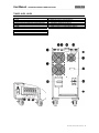
ENGLISH TOWER AND RACK UPS USER MANUAL DOUBLE CONVERSION UPS User Manual - ONLINE 6K/10K RACK-TOWER ISOTX UPS ENGLISH _____________________________________________________________________________________________________________________ TABLE OF CONTENTS 1. SAFETY 2. AVAILABLE MODELS 3.- UPS INSTALLATION: SITE PLANING SITE INSPECTION & INSTALLATION CONDITIONS RACK UPS INSTALLATION TOWER UPS INSTALLATION EXTERNAL CIRCUIT BREAKERS SELECTION WIRING SELECTION 4.- UPS INSTALLATION: SINGLE UPS - TERMINAL BLOCK UPS AC LINES CONFIGURATION AC TERMINAL BLOCKS EXTERNAL BATTERY CONNECTION 5.- UPS INSTALLATION: PARALLEL UPS - TERMINAL BLOCK GENERAL COMMENTS UPS AC LINES CONNECTION PARALLEL CONTROL CABLES CONNECTION 6.- START-UP: SINGLE UPS INSPECTION BEFORE START-UP SINGLE UPS - START UP PROCEDURE 7.- START-UP: PARALLEL UPS REQUIREMENTS FOR PARALLEL UPS SYSTEMS INSPECTION BEFORE START-UP PARALLL UPS - START UP PROCEDURE 8.- OPERATION INTERFACE FRONT PÀNEL: PUSH BUTTONS / LEDS / LCD 9.- OPERATION: SINGLE UPS 10.- OPERATION: PARALLEL UPS REMOVING UPS FROM PARALLEL SYSTEM ADDING UPS TO PARALLEL SYSTEM 11.- UPS CONFIGUIRATION 12.- ERROR CODES, ALARMS & TROUBLESHOOTING 13.- TECHNICAL SPECIFICATIONS 14.- WARRANTY 20150105 Tower-Rack 6K-10K ISOTX - 2 User Manual - ONLINE 6K/10K RACK-TOWER ISOTX UPS ENGLISH _____________________________________________________________________________________________________________________ 1. GENERAL SAFETY INSTRUCTIONS . WARNING: It is required to read and understand this manual. Follow all instructions given in this manual for starting up and operating this product. Only qualified technician must start-up, operate and maintain this product. Keep manuals as a guide for future consults. WARNING: This product operates with dangerous voltages. It must be installed, operated and maintained ONLY by qualified technicians trained for this kind of products. Service personnel MUST know and understand very well all electric risks related to this product. UPS manufacturer or distributor will never be responsible for any accident produced by lack of knowledge or negligent practices at the moment of install, starting up or maintain this product. UPS manufacturer or distributor is not liable for any damage that might rise from misusing this unit or defective installation. WARNING: If you are not qualified technician do not try to install, operate or repair this product. WARNING: Do not try to install, operate or repair this product if you are not accompanied by another qualified person able to offer first aid support in case of emergency or accidents. WARNING: Internal area of this product is locked by screws. Do not try to access inside the UPS unless you are a qualified technician. UPS must be checked, repaired and maintained by qualified personnel only. CAUTION!!: ELECTRIC SHOCK RISK CAUTION: There are dangerous voltages in the UPS power outlets although the equipment is not plugged to power line. CAUTION: Inside this equipment, due to internal batteries, there are ALWAYS dangerous voltages, thought the UPS is OFF and unplugged of power line. CAUTION: There are dangerous voltages in DC (Direct Current) Capacitors. Please Check Capacitor location in Figure 8.4.1. Wait at least 10 minutes after turning off UPS before opening it to access inside. DANGER: Power off UPS and unplugged it from AC Line before opening it to Access inside this unit. CAUTION: Before starting the opening procedure, remove all jewelry and metallic objects such as: Rings, Watches, Bracelets, etc., because they could contact conductive parts and components inside the UPS and this might cause discharges and/or short circuits. Make sure using tools properly isolated to avoid electrical risks. Transportation and Storage: Warnings and Recommendations WARNING: This UPS must be transported only in its original package to be properly protected WARNING: This equipment must be storage in dry and ventilated site, in upright position. WARNING: Before storage this UPS, batteries must be recharged for 8 to 10 hours WARNING: During long term storage UPS must be recharged periodically according to this manual. WARNING: EQUIPMENT DISPOSAL Out of service units: It is strongly recommended to dispose this piece of equipment according to valid directives in your country. At the moment of disposing all pieces need to be managed appropriately to avoid possible environmental damage or for some materials to be recycled. Batteries: Do not throw it to fire (risk of explosion). Do not open the batteries, there are dangerous liquids inside WARNING: BATTERIES MAINTENANCE • • • • • Batteries capacity, in general (of all kinds), decrease with time and use. Our products contain high quality batteries only. Batteries useful life in our UPS is between 4 and 5 years, considering environment temperature under 25 ºC and optimal operational conditions. This time can be dramatically reduced by high temperature and other adverse operation condition. Batteries life expectancy may be also affected by other operation conditions such as electrical service quality as well as number and kind of equipments connected to UPS Batteries should be periodically tested to check capacity and assure and appropriate back up. • • To enlarge batteries life expectancy it is recommendable to fully discharge UPS one every 2 to 3 months During UPS storage recharge batteries according to the following table: Storage Temperature -25°C a +30°C +30°C a +45°C Recharging Frequency Every 4 months Every 2 months Recharging Time During 6 hours During 6 hours 20150105 Tower-Rack 6K-10K ISOTX - 3 User Manual - ONLINE 6K/10K RACK-TOWER ISOTX UPS ENGLISH _____________________________________________________________________________________________________________________ SAFETY STANDARDS SAFETY: IEC/EN 62040-1 EMI (Radiated): IEC/EN 62040-2 (Cat 3) EMI (Conducted): IEC/EN 62040-2 (Cat 3) EMS Power-Frequency Magnetic Field: EMS Low Freq. Signals: IEC/EN 61000-4-8 (Level 4) IEC/EN 61000-2-2 EMS (ESD): IEC/EN 61000-4-2 (Level 4) EMS (RS): IEC/EN 61000-4-3 (Level 3) EMS (EFT): IEC/EN 61000-4-4 (Level 4) EMS (SURGE): IEC/EN 61000-4-5 (Level 4) EMS (CS): IEC/EN 61000-4-6 (Level 3) This product has been designed to operate in industrial and commercial applications. If it is used in different application some considerations for avoiding interferences could be necessary. 20150105 Tower-Rack 6K-10K ISOTX - 4 User Manual - ONLINE 6K/10K RACK-TOWER ISOTX UPS ENGLISH _____________________________________________________________________________________________________________________ 2. AVAILABLE MODELS - UPS TOWER: 6K-EX & 10K-EX: UPS with internal batteries and connection for external battery cabinets to increase backup time. - UPS TOWER: 6KEX & 10KEX with ISO TX Models with isolation transformer to provide galvanic isolation between input and output as well as Dual Output: 110Vac/220Vac (2 isolated phases of 110Vac each: L1-N1; L2-N2) - UPS RACK: RACK 6K-EX & 10K-EX: UPS for rack mounting with external battery connection capabilities to increase backup time. - Optional Accessory: Isolation Transformer ISOTX for RACK UPS 6K-EX & 10K-EX: ISOTX for RACK UPS is an optional external module can be connected at any moment to the UPS. Model 6KEX / 10KEX 6KEX / 10KEX ISOTX Rack 6KEX/10KEX Internal Batteries Y Ext. Batt. Connector Y Isolation Transformer No Y Y Y (in separate module) Y ** Note A ** Note A: ISOTX module for Rack UPS is an accessory available in a separate optional “3U” height module. EXTERNAL BATTERIES EX model ups also supports additional external battery cabinets to increase backup time. External Battery Cabinet for Tower type 6K-EX & 10K-EX: Model: EX-BAT-T6/T10 Batteries: 40 pieces: 2 groups connected in parallel. 20 batteries of 12V-9AH in each group DC Voltage: 240Vdc External Battery Cabinet for Rack type Rack 6K-EX & 10K-EX: Model: EX-BAT-R6/T10 Batteries: 20 pieces: 1 group of 12V-9AH DC Voltage: 240Vdc NOTE: 6K/10K Rack Models are supplied in 2 separate modules: 1 for UPS electronic and 1 for Main Battery Module (20 pieces x 12V batteries) 20150105 Tower-Rack 6K-10K ISOTX - 5 User Manual - ONLINE 6K/10K RACK-TOWER ISOTX UPS ENGLISH _____________________________________________________________________________________________________________________ TOWER 6K-EX, 10K-EX 1.- RS232 2.- USB 3.- EPO (Emergency Stop / Parada Emergencia) 4.- Share Current (for parallel UPS / para UPS paralelas) 5.- Parallel Port (for parallel UPS / para UPS paralelas) 6.- SNMP 7.- FAN (ventilación Forzada) 9.- MBS (Bypass Switch / Interruptor Bypass) 10.- AC Input Breaker / Breaker Entrada AC 11.- FAN ISOTX (Ventilación para ISOTX) 12.- Terminal block cover / Tapa Regleta Conexiones 13.- EXBATT connector / Conector Baterías Externas 15.- AC INPUT / ENTRADA AC 16.- AC Output 1 / Salida AC No. 1 (Standard) 17.- AC Output 2 / Salida AC No. 2 (Programable) 20150105 Tower-Rack 6K-10K ISOTX - 6 User Manual - ONLINE 6K/10K RACK-TOWER ISOTX UPS ENGLISH _____________________________________________________________________________________________________________________ TOWER 6K-EX, 10K-EX with ISO TX 1.- RS232 2.- USB 3.- EPO (Emergency Stop / Parada Emergencia) 4.- Share Current (for parallel UPS / para UPS paralelas) 5.- Parallel Port (for parallel UPS / para UPS paralelas) 6.- SNMP 7.- FAN (ventilación Forzada) 9.- MBS (Bypass Switch / Interruptor Bypass) 10.- AC Input Breaker / Breaker Entrada AC 11.- FAN ISOTX (Ventilación para ISOTX) 12.- Terminal block cover / Tapa Regleta Conexiones 13.- EXBATT connector / Conector Baterías Externas 15.- AC INPUT / ENTRADA AC 18.- Isolated Output 1 / Salida Aislada No. 1 (120V) 19.- Isolated Output 2 / Salida Aislada No. 2 (120V) 20.- NON Isolated Neutral / Neutro NO Aislado 20150105 Tower-Rack 6K-10K ISOTX - 7 User Manual - ONLINE 6K/10K RACK-TOWER ISOTX UPS ENGLISH _____________________________________________________________________________________________________________________ RACK: RACK 6KEX / 10KEX UPS MODULE 1. 2. 3. 4. 5. 6. 7. 8. 10. RS-232 USB EPO” (Emergency Power Off) Share Current Port (for parallel function) Parallel Port (for parallel function) SNMP Intelligent Slot Cooling Fans External Bypass Switch port (MBS port) Main AC Input Breaker 13. 14. 16. 17. 18. Terminal Block Cover TB: AC output DC Connector for external batteries TB: AC Input TB: Ground BATTERY MODULE 16. DC Connectors 19. DC Breaker UPS MODULE: BATTERY MODULE: ISOTX MODULE: 20150105 Tower-Rack 6K-10K ISOTX - 8 User Manual - ONLINE 6K/10K RACK-TOWER ISOTX UPS ENGLISH _____________________________________________________________________________________________________________________ 3.- UPS INSTALLATION: SITE PLANING SAFETY INSTRUCTIONS WARNING: Before revising this section you must read and understand very well section 1 of this manual: “GENERAL SAFETY INSTRUCTIONS”. WARNINGS, RECOMMENDATIONS AND LIABILITY LIMITATION REACH AND LIABILITY LIMITATION: The preparation of the site, wiring and all protection devices must be supplied by end user and it will not be responsibility neither the UPS distributor nor the UPS technician in charge of the start-up. The place will be conditioned be end user or electrical contractor and must fulfill with local normative and directives and UPS technical requirements. This manual describes minimal conditions and technical requirements with which the site must accomplish. Directives and requirements described in this manual, do not pretend to substitute in any way local electrical directives or normative. In some cases, local directives or regulations might be more exigent than UPS technical requirements described by this manual. In that case end user electrical contractor must be sure to comply with all related local electrical regulations and directives. WARNING: Power lines must be protected by protection devices against over current (breakers) or leak currents with capacity and technology appropriate to effectively accomplish its function. Moreover, installation grounding must be correct. WARNING: Install the UPS in well ventilated locations and leave room enough between UPS and close objects and structures WARNING: Do not connect to UPS equipments or devices that exceed its capacity, this would overload the UPS. WARNING: This product has been designed to be used indoors protected from water, direct sun light, dust and extreme temperature. WARNING: Do not put any object on the UPS; do not apply any force over UPS. Do not cover UPS ventilation. WARNING: This UPS must be connected to appropriate electrical service according to selected model. Technical specs sticker in the UPS shows the UPS power ratings. DO NOT connect this UPS to any of its own power outlets, this could damage the unit permanently. WARNING: Do not connect AC motor based equipments without a careful sizing of the UPS based on inrush current instead of average current. Inrush current typical of motor based system could overload this UPS. 20150105 Tower-Rack 6K-10K ISOTX - 9 User Manual - ONLINE 6K/10K RACK-TOWER ISOTX UPS ENGLISH _____________________________________________________________________________________________________________________ SITE INSPECTION AND INSTALLATION CONDITIONS . REGULATIONS AND LEGAL DIRECTIVES It is necessary to check that installation site, wiring and power protection in the installation supplied by end user, fulfill technical parameters required by UPS. A particular installation might accomplish with UPS requirements but not with local directives and regulations. The end user and/or electrical contractor will be responsible of watching for complying with electrical regulations and normative during electrical installation managed by end user. Inspection performed by installation technician is not intended to confirm regulations and directives accomplishing but only with technical needs for optimal UPS operation. SITE INSPECTION • • • • • During transport of this UPS from a cold place to a warmer and more humid one, some condensation could be generated. Leave the UPS for at least 2 hours to climate to new installation site. Do not install the UPS outdoors or near water sources nor in wet environment Do not install the UPS in sites exposed to sun light or heat sources. Temperature at operation site should never rise over 35 ºC. Batteries’ life shortens over 25 ºC. Installation site must be dry, fresh, free of dust, fibers and any other objects (conductors or not) suspended in the air that could get into the UPS thru the ventilation system (Fan). Do not block UPS ventilations UPS INPUT AND OUTPUT POWER LINES PROTECTION AC LINES PROTECTIONS DEVICES: All UPS Inputs and outputs must be protected by circuit breakers and current leak protections. Protection capacity and type must fulfill local regulations as well as directives from this manual. Grounding must be according to local directives as well. DC PROTECTIONS DEVICES: For Ex models (with external batteries) there must be also DC Circuit Breakers between UPS and battery bank. Some Models include a DC breaker on the rear panel for external battery pack protection; otherwise an external DC Circuit breaker must be installed. MATERIALS AND ELECTRICAL DEVICES WARNING: Verify that all electrical lines involved in installation are open circuits and free of dangerous voltages before starting inspection tasks. All switches related to these electrical lines must be in “OFF” position before starting UPS installation. After disconnecting power from electrical lines involved in installation, check again with a digital voltmeter that are free of dangerous voltages. IMPORTANT: Warning label must be placed on primary involved circuit breakers to alert there are maintenance personnel working on these circuits to avoid accidental actuation on involved breakers. 20150105 Tower-Rack 6K-10K ISOTX - 10 User Manual - ONLINE 6K/10K RACK-TOWER ISOTX UPS ENGLISH _____________________________________________________________________________________________________________________ RACK UPS INSTALLATION Rack UPS must be installed using L-Shape type guides for supporting UPS weight. Usually this kind of supports is provided with rack cabinets. If not, UPS distributor can provide original telescopic guides as optional accessory. Small black handles included with the UPS are only for locking purposes. UPS cannot be supported only by these handles. - Figure 1: Rack cabinet must include L-shape guide to support UPS. Figure 2: UPS must be installed on L-shape guides. Figure 3: Handles included with UPS are only for locking UPS to the cabinet but not for supporting UPS weight. Figure 4: Original telescopic guides can be provided as optional accessory if it is required. Figure 1: Figure 2: Figure 3: Figure 4: 20150105 Tower-Rack 6K-10K ISOTX - 11 User Manual - ONLINE 6K/10K RACK-TOWER ISOTX UPS ENGLISH _____________________________________________________________________________________________________________________ TOWER UPS INSTALLATION SITE CONSIDERATIONS * This product has been designed to be used indoors, protected from water, direct sun light, dust and extreme temperature. * Install the UPS in well ventilated location or air conditioned room. Temperature must be always in acceptable range according to technical specifications table of this manual. It is strongly recommendable controlled room temperature between 21ºC to 24ºC for longer battery and UPS life. * There must be minimum 1 meter free room distance between UPS and any wall or object. It will allow better ventilation and it will allow service UPS when required. * Do not put any object on the UPS; do not apply any force over UPS. Do not cover UPS ventilation. ELECTRICAL REQUIREMENTS (MANDATORY) * All Power lines must be protected by magneto-thermal protection devices against over current (breakers) with capacity and technology appropriate to effectively accomplish its function as indicated in this manual. Moreover, installation grounding must be correct. * This UPS must be connected to appropriate electrical service according to selected model. Technical specs sticker in the UPS shows the UPS power ratings. DO NOT connect this UPS to any of its own power outlets, this could damage the unit permanently. * Connect only computer related equipments to this UPS. DO NOT connect medical equipments or critical availability equipments to this UPS. DO NOT connect AC motor based equipments. DO NOT connect home appliances (ovens, vacuum cleaners, refrigerators, etc.) to this UPS. 20150105 Tower-Rack 6K-10K ISOTX - 12 User Manual - ONLINE 6K/10K RACK-TOWER ISOTX UPS ENGLISH _____________________________________________________________________________________________________________________ CIRCUIT BREAKERS SELECTION UPS Input: 220VAC, Single phase + Neutral - UPS Output: 220VAC, Single phase + Neutral MODEL 6KVA (220Vac) 10KVA (220Vac) Input: 220Vac Output: 220Vac 40 Amps (curve: D) 63 Amps (curve: D) 40 Amps (curve: D) 63 Amps (curve: D) External Battery Connection *** Note 3 50 Amps (curve: C) 50 Amps (curve: C) ISOTX MODEL: UPS Input: 220VAC, Single phase + Neutral - UPS Dual Output: 110/220Vac (Includes Galvanic Isolation Transformer, 2 x 110VAC isolated outputs Phase–Neutral) 2 Individual One Total 110Vac MODEL Input: 220Vac 110Vac Outputs Output Note 1 Note 2 6KVA ISOTX 40 Amps 40 Amps 80 Amps (Dual Output) (curve: D) (curve: D) (curve: D) 10KVA ISOTX 63 Amps 63 Amps 125 Amps (Dual Output) (curve: D) (curve: D) (curve: D) External Battery Connection *** Note 3 50 Amps (curve: C) 50 Amps (curve: C) Note 1: When using two 110Vac outputs independently, each output phase (110Vac Line-Neutral) must have electrical protection with ratings and capacity according to table. IMPORTANT: Each individual output manages half of total UPS capacity. Note 2: When connecting two 110Vac outputs in parallel (as shown in Figure 3.2.3-B to offer one single 110Vac output with 100% UPS capacity, electric protection circuit breakers must be as shown in the table (One Total 110Vac Output). Note 3: If external battery cabinets are connected to UPS, it is necessary to install one DC breaker between UPS and each external battery cabinet. WIRES: TYPE AND GAUGE Section or Gauge of the wires used in the installation must be rated to manage current values as indicated in below table. WIRE SELECTION ISOTX MODELS: Two 120Vac Outputs 220Vac MODELS UPS MODEL 6KEX 6KEX ISOTX 10KEX 10KEX ISOTX OUTPUT 1 110Vac OUTPUT 2 110Vac UNIQUE OUTPUT 110Vac X X X X 40 Amp. (AC) 40 Amp. (AC) 80 Amp. (AC) 63 Amp. (AC) 63 Amp. (AC) X X X X X 63 Amp. (AC) 63 Amp. (AC) 125 Amp. (AC) INPUT 220Vac 40 Amp. (AC) OUTPUT 220Vac 40 Amp. (AC) X GROUND 40 Amp. (AC) 40 Amp. (AC) 63 Amp. (AC) 63 Amp. (AC) EXTERNAL BATTERIES 240VDC 40 Amp. (DC) 40 Amp. (DC) 63 Amp. (DC) 63 Amp. (DC) Values in Amps. AC: Alternate Current. DC: Direct Current WARNING: The correct wire gauge or section is strongly affected by diverse factors such as: Operation temperature, wire length, type of wire and kind of installation. UPS user and/or his electrical contractor must assure an appropriate selection for wire and other devices for complying with local regulations and directives for electrical installations. NOTE 1: Wires for 6K (6K y 6KEX) models with 208-240 VAC should be able to manage 40 Amps. NOTE 2: Wires for 6K (6K y 6KEX) models with 208-240 VAC should be able to manage 63 Amps. NOTE 3: Models with Dual Outputs (with isolation transformer): Each independent 110VAC line manages just half of total UPS power WARNING: For ISO-TX models: When connecting two individual 110VAC outputs together (see figure in section 3.2.3), take into consideration that total current will be twice the single phase current. Keep this in mind for selecting the appropriate wire size. For model 6K output cable must be rated to manage 80Amps AC. For 10K model output cable must be rated to manage 125Amps AC. NOTE 4: Wiring colors must be selected according to local directives and regulations LEAK CURRENT PROTECTION In many countries, now a day, it is legally required to install protections against current leakage to protect human beings in cases of leaks o discharges to ground. It is responsibility of the end user and/or electrical contractor selecting and including these protection devices in the electrical circuit of the UPS. 20150105 Tower-Rack 6K-10K ISOTX - 13 User Manual - ONLINE 6K/10K RACK-TOWER ISOTX UPS ENGLISH _____________________________________________________________________________________________________________________ 4.- UPS INSTALLATION: SINGLE UPS - TERMINAL BLOCK AC LINES CONNECTION PROCEDURE • • . Make sure the UPS is Off before starting the installation. Remember to check all wires to be connected are not powered (including external batteries). UPS terminal block preparation Remove cover of terminal block at the UPS rear panel, identified as 12 in rear panel section of this manual DO NOT use a wall power outlet to plug UPS to AC Line as usually ratings of this kind of outlets are not enough to power 6KVA UPS. UPS Input wire must be connected by breaker protected line to electric panel board. UPS Input and Output Connection Connect input and output ground wires to proper place on the UPS chassis on both sides of terminal blocks. Ground wires must be FIRST to be connected and LAST to be disconnected. Connect UPS input and output wires according to your UPS model or configuration as described in following figures: TOWER TYPE 6 / 10K . TOWER TYPE 6K / 10K ISO - WITH INTERNAL ISO-TX . INT. BLOCK DIAGRAM • • Output 1: Output with Galvanic Isolation, 110Vac between phase and Neutral with 50% of total UPS capacity. Output 2: Output with Galvanic Isolation, 110Vac between phase and Neutral with 50% of total UPS capacity. 20150105 Tower-Rack 6K-10K ISOTX - 14 User Manual - ONLINE 6K/10K RACK-TOWER ISOTX UPS ENGLISH _____________________________________________________________________________________________________________________ ISO-TX UPS MODEL CAN BE CONFIGURED IN 3 DIFFERENT MANNERS 1) TWO separate 110Vac isolated outputs. Each 50% of total UPS capacity 2) ONE 110Vac output. Output Power: 100% UPS Total Capacity 3) ONE 220Vac Isolated Output. Output Power: 100% UPS Total Capacity 20150105 Tower-Rack 6K-10K ISOTX - 15 User Manual - ONLINE 6K/10K RACK-TOWER ISOTX UPS ENGLISH _____________________________________________________________________________________________________________________ RACK TYPE UPS 6-10K . Optional ISOTX Module for RACK UPS 6-10K ISOTX module is optional accessory rack module. UPS AC output must be connected to ISOTX input as indicated. ISOTX outputs can be configured as tower UPS models. 20150105 Tower-Rack 6K-10K ISOTX - 16 User Manual - ONLINE 6K/10K RACK-TOWER ISOTX UPS ENGLISH _____________________________________________________________________________________________________________________ EXTERNAL BATTERY CABINETS – CONNECTION PROCEDURE . UPS Tower type 1.- Check all DC breakers are in OFF position 2.- Remove all DC connector covers in UPS and EXBATT cabinets 3.- Using appropriate cable (supplied with the EXBATT) connect UPS with EXBATT 1. In case of more than 1 EXBATT connect EXBATT 1 with EXBATT 2 and so on until last EXBATT. 4.- Activate DC breakers one by one in EXBATT cabinets to connect EXBATT batteries with internal UPS Main batteries. UPS RACK type 20150105 Tower-Rack 6K-10K ISOTX - 17 User Manual - ONLINE 6K/10K RACK-TOWER ISOTX UPS ENGLISH _____________________________________________________________________________________________________________________ 5.- UPS INSTALLATION: PARALLEL UPS - TERMINAL BLOCK . GENERAL COMMENTS FOR PARALLEL SYSTEMS * 6K y 10KVA models allow installation of up to 3 units in parallel. * Units to work in parallel must be connected as indicated in this section. * Parallel system must be configured and started up according to instructions given dedicated section of this manual. * Any mistake in connection, configuration or starting up procedure could produce permanent damage UPS PARALLEL UPS CONNECTION • Make sure the UPS is Off before starting the installation • Remember to check all wires to be connected (including external batteries) are not powered before manipulating them. UPS TERMINAL BLOCK PREPARATION Remove cover of terminal block at the UPS rear panel, identified as 12 in rear panel section of this manual DO NOT use a wall power outlet to plug UPS to AC Line as usually ratings of this kind of outlets are not enough to power 6KVA UPS. UPS Input wire must be connected directly to electric panel board. UPS INPUT AND OUTPUT CONNECTIONS Connect input and output ground wires to proper place on the UPS chassis on both sides of terminal blocks. Ground wires must be FIRST to be connected and LAST to be disconnected. Refer to Figures 3A and 3B. a) Grounding Wires: Connect AC Input and Output ground of both UPS according to figures. b) AC Input Wires: AC Input wires must come from individual electrical circuit breakers on electrical panel board before being connected to UPS terminal block. c) AC Output Wires: AC output wires must be connected directly to external circuit breakers of bigger capacity. d) If UPS is EX model, external battery banks must be connected to dedicated connector located in rear panel of UPS. e) Control Cables for Parallel Connection: Connect Parallel Cable and shared current according to figures. WARNING – EXTERNAL BATTERIES: If UPS to be connected in parallel have external batteries it is mandatory each UPS counts with its own battery pack. Parallel connection cannot be performed if only one of two (or two or three) UPS have external batteries. Permanent damages will be produced in UPS if this warning is not followed. 20150105 Tower-Rack 6K-10K ISOTX - 18 User Manual - ONLINE 6K/10K RACK-TOWER ISOTX UPS ENGLISH _____________________________________________________________________________________________________________________ MODEL 6K / 10KEX: PARALLEL UPS - AC LINES CONNECTION 20150105 Tower-Rack 6K-10K ISOTX - 19 User Manual - ONLINE 6K/10K RACK-TOWER ISOTX UPS ENGLISH _____________________________________________________________________________________________________________________ MODEL 6K / 10K ISOTX: PARALLEL UPS - AC LINES CONNECTION 20150105 Tower-Rack 6K-10K ISOTX - 20 User Manual - ONLINE 6K/10K RACK-TOWER ISOTX UPS ENGLISH _____________________________________________________________________________________________________________________ PARALLEL UPS - CONTROL WIRES CONNECTION 20150105 Tower-Rack 6K-10K ISOTX - 21 User Manual - ONLINE 6K/10K RACK-TOWER ISOTX UPS ENGLISH _____________________________________________________________________________________________________________________ 6.- START-UP: SINGLE UPS INSPECTION BEFORE START UP 1. 2. 3. 4. 5. 6. Make sure all wires are tightly connected to terminal block. Any loose connection will produce overheating, failures and damage to UPS. Make sure all instructions of sections 3 and 4 have been performed correctly. Put the terminal block cover back in its position to avoid access to wiring Check EPO connections. • EPO Port closed (Wired): EPO function disabled • EPO port connected to an emergency switch: EPO function available by activation of Emergency Switch; which must be “Normally Closed” type in order to guarantee that UPS will shut down when circuit opens. Check Maintenance Bypass Switch (MBS) located in UPS rear panel is in UPS position and its cover is duly installed. Make sure all external protection devices in input and output lines are in open (OFF) position. SINGLE UPS - START UP PROCEDURE 1. 2. 3. 4. 5. Make sure all equipments connected to UPS are off Power AC input at electrical panel board by setting input AC Lines Circuit Breaker to ON Put Battery Bank breaker to ON (Only for Ex Models, If using external battery pack) Put AC INPUT Breaker to ON in UPS rear panel. LCD in front panel starts to show bypass mode. UPS Outputs are powered although UPS is off because it is on By-Pass mode. At this moment output power is being supplied by AC Input Power Line. 6. Start up the UPS by pressing On push button in front panel until beep is heard and ON message displayed on top of the LCD. 7. Few seconds after, the UPS leaves By-Pass mode to enter in Normal Online Mode, also known as “AC Mode” 8. Power on sequentially each protected equipments. The front panel LCD should show the load increase as equipments start. 9. Once all equipments are on, the total power consumption (load) should not exceed UPS capacity. 10. At this moment UPS working under NORMAL AC-MODE and the system is supplied by UPS. NOTE 1: If any error or warning message in indicated in LCD please revise Troubleshooting section of this manual. NOTE 2: UPS batteries maybe are not fully charged. UPS could require about 4 to 6 hours to recharge batteries up to 100% of their capacity. 20150105 Tower-Rack 6K-10K ISOTX - 22 User Manual - ONLINE 6K/10K RACK-TOWER ISOTX UPS ENGLISH _____________________________________________________________________________________________________________________ 7.- START-UP: PARALLEL UPS REQUIREMENTS FOR PARALLEL SYSTEM WARNING: Before starting up this parallel UPS system is mandatory to comply with all below requirements. 1.- Maximum quantity of UPS to be connected in parallel is 3. Do not try to connect more than 3 units in parallel. 2.- All UPS to be connected in parallel system must be same model (all 6K or all 10K) with same firmware version. Please ask your distributor to confirm firmware is the same in case of doubts. UPS belonging to same manufacturing batch have same firmware version. 3.- UPS configuration (configuration parameters of LCD menu) must be the same for all UPS. 4.- All MBS (Maintenance Bypass Switch) located in rear panels must be in "UPS" position and switch covers must be properly installed. 5.- In case of using external battery packs, each UPS must has same external battery packs quantity and type. 6.- All control parallel cables (parallel cables and current share cables) must be properly connected in UPS rear panels as indicated in section 5 of this manual. 7.- Make sure total available capacity (in Watts) of all UPS to be connected in parallel is higher than load to be connected to UPS system. It is recommendable total UPS power is at least 25% higher to total load. If UPS system will work as n+1 redundant system, make sure total UPS capacity after removing one UPS is higher than maximum load to be connected. If not remaining UPS will not be able to support connected load when one of the units was removed. INSPECTION BEFORE START UP 1. Make sure all wires are tightly connected to terminal block. Any loose connection will produce overheating, failures and damage to UPS. 2. Make sure all instructions of sections 3 and 5 have been performed correctly. 3. Put the terminal block cover back in its position to avoid access to wiring 4. Check EPO connections. • EPO Port closed (Wired): EPO function disabled • EPO port connected to an emergency switch: EPO function available by activation of Emergency Switch; which must be “Normally Closed” type in order to guarantee that UPS will shut down when circuit opens. 5. Check Maintenance Bypass Switch (MBS) located in UPS rear panel is in UPS position and its cover is duly installed. 6. Make sure all external protection devices in input and output lines are in open (OFF) position. 7. Check control parallel cables are connected according to section 5 of this manual. 20150105 Tower-Rack 6K-10K ISOTX - 23 User Manual - ONLINE 6K/10K RACK-TOWER ISOTX UPS ENGLISH _____________________________________________________________________________________________________________________ START UP FOR PARALLEL UPS SYSTEM WARNING: Make sure all requirements and previous inspection have been revised and complied before initiating start up procedure. If not please do not try to continue with start-up procedure. 1.- Make sure all equipments to be protected and connected to UPS output are in OFF condition. 2.- Check AC input breaker located in UPS rear panels is in OFF position in all UPS of the system. 3.- Power on external main AC input in electrical panel. Set to ON position all external AC input breakers. 4.- If UPS are using external battery packs, set to ON all DC breakers to connect external DC packs to UPS. 5.- For UPS No. 1: Set to "ON" AC input breaker located in rear panel of UPS No. 1. Wait until UPS No.1 completes autochecking and Bypass LED lights continuously. 6.- For UPS No. 2: Set to "ON" AC input breaker located in rear panel of UPS No. 2. Wait until UPS No.2 completes autochecking and Bypass LED lights continuously. 7.-In case of having 3 UPS in the system, proceed in similar manner with UPS No. 3. IMPORTANT: AC input breakers activation must be done in one by one and not at same time. First for UPS No. 1, then for UPS No. 2 and finally for UPS No. 3 (if you have a parallel system with 3 UPS). If AC input breakers are activated all at same time, warning message "3F" could be activated. If it occurs, reinitiate procedure sequentially. Warning 3F message must be previously reset according to warning and error section in this manual 8.- When rear panel AC breaker is set to "ON", This UPS recognizes all other UPS previously powered ON in the parallel system and will get its own parallel identification as PAR 00X, where X is the position according to power on sequence. PAR 001 for 1st UPS powered on, PAR 002 for 2nd and PAR 003 for 3rd UPS. This message is only indicated in UPS manufactured after Dec-2011. If UPs is before Dec-2011 continue without waiting for PAR 00X message. 9.- At this moment all UPS LCDs must turn on to indicate internal circuitry in UPS is been powered. ** If bypass mode is allowed, all UPS will go to bypass mode. ** If bypass mode is not allowed by configuration, all UPS will go to a kind of stand-by mode with outputs open and powered off waiting until ON command is selected in UPS front panel. 10.- At this moment configuration menu in each UPS LCD must be revised to select desired configuration. It is mandatory to use same configuration in all configuration parameters for all UPS of the system. 11.- Once configuration has been selected and verified, all UPS can be started up by selecting "ON" push button in front panel. Please press "ON" push button for each UPS. One long "beep" will be generated. "ON" message will be displayed on top side of LCD. 12.- All UPS will go to NORMAL Online mode at same time. 13.- Before setting to "ON" all external output breakers please revise AC voltage output on each UPS. ** Please measure AC output voltage using a digital multi-meter and confirm all output voltages are similar. Maximum acceptable deviation should be 3Vac or lower. Typically 1Vac. ** If output voltage values are higher than 3Vac, we suggest to adjust them by function 15 . You can reduce (Sub) or increase (Add) voltage output voltage for each UPS as required. 14.- If AC output voltages are as expected, please set to "ON" external output breakers for all UPS progressively. Start with UPS Nº 1, then UPS Nº2, etc. After that, all UPS outputs are connected in parallel. 15. Check to confirm there are no error or alarm messages on LCDs. At this moment all UPS are working in NORMAL Online mode and connected in parallel. 16.- It is time to power on equipments connected to UPS output. Power on progressively one by one. Check on UPS LCDs how power output rises meanwhile equipments are powered on. ** Once all output load is connected check power output is below 100%. ** At this moment, UPS parallel system is powering your system in NORMAL Online mode. 20150105 Tower-Rack 6K-10K ISOTX - 24 User Manual - ONLINE 6K/10K RACK-TOWER ISOTX UPS ENGLISH _____________________________________________________________________________________________________________________ 8.- OPERATION INTERFACE UPS FRONT PANEL: PUSH BUTTON RACK FRONT PANEL TOWER FRONT PANEL Both Rack and Tower type UPS offer same 4 function buttons as described below: ON / ENTER POWER ON : Keep selected during 1 second to power UPS ON. ENTER : It Works as “ENTER” or confirmation function when LCD is in configuration menu mode. OFF / ESCAPE POWER OFF : Keep selected to turn UPS OFF. ESCAPE : It Works as ESCAPE key when LCD is in configuration menu mode. TEST / UP BATTERY TEST : When UPS is in normal mode by selecting TEST key UPS enters into battery test mode during 10s. UP : It Works as UP key when LCD is in configuration menu mode. MUTE / DOWN ALARM MUTE : It mutes alarm beep in progress. DOWN : It Works as DOWN key when LCD is in configuration menu mode, TEST / UP + MUTE / DOWN - Simultaneous Activation CONFIGURATION MODE : UPS enters into configuration menu when these 2 keys are activated at same time during 1s UPS FRONT PANEL: LED INDICATOR LIGHTS There are 4 LED indication lights in front panel, located below LCD. These 4 LEDs describe UPS condition as follow: Bypass Line Battery Fault UPS is in Auto-check mode during start-up. ● ● ● ● BYPASS Mode ● ○ ○ ○ NORMAL Mode ○ ● ○ ○ BATTERY Mode ○ ○ ● ○ BATTERY TEST in progress ● ● ● ○ ECO Mode Activated ● ● ○ ○ UPS in Failure ○ ○ ○ ● MODE ● LED = ON / ○LED = OFF 20150105 Tower-Rack 6K-10K ISOTX - 25 User Manual - ONLINE 6K/10K RACK-TOWER ISOTX UPS ENGLISH _____________________________________________________________________________________________________________________ UPS FRONT PANEL: LCD This UPS has a sophisticated LCD able to display all important information related to input line, UPS status and values, operation mode and error and alarm messages. It is a powerful information tool to know what is happening at any moment. LCD is also the configuration interface for all configurable parameters. 1.- BATTERY INFORMATION: In this section is displayed battery charging level and battery alarms/error icons. 2.- ELAPSED TIMER: When UPS switches to battery mode, elapsed time during battery mode is displayed in Hours/Minutes/Seconds. 3.- ERROR / ALARM CODE: In case of alarm or error, 2 digits code is displayed in this section to describe the kind of error or alarm. Revise error and alarm codes tables in this manual. 4.- BEEP STATUS: It shows if audible alarm buzzer is active or muted. 5.- LOAD INFORMATION: In this section is displayed load value connected to UPS by 4 segments displays: (0-25%), (25%-50%), (50%-75%) and (75%-100%). It also shows error and alarm icons related to UPS output. 6.- UPS MODE: All possible UPS modes are indicated by this section in graphic way. 7.- INPUT / OUTPUT VALUES: Input and output voltage and frequency values can be monitored in this LCD section. In battery mode this section shows battery DC voltage. 20150105 Tower-Rack 6K-10K ISOTX - 26 User Manual - ONLINE 6K/10K RACK-TOWER ISOTX UPS ENGLISH _____________________________________________________________________________________________________________________ 9.- OPERATION: SINGLE UPS . This is a True On Line Double Conversion UPS and it is designed to offer clean, bump-less and highest quality power to your computer related equipments protecting also your valuable data. Power delivered by UPS is 100% sine wave as main line. According to AC Line status the UPS may operate in following modes: ONLINE NORMAL Mode . BATTERY Mode (Also known Inverter Mode) . ECO Mode . BY PASS Mode . FREQUENCY CONVERSION Function . When UPS is turned off by selecting ON push button in front panel and AC Line is normal it enters into ONLINE NORMAL mode. Under this mode UPS Inverter powers outputs and the energy is taken from DC voltage coming from AC/DC converter. Batteries are charged by AC Line if required. Under ONLINE NORMAL mode when UPS detects a problem in AC input Line or black out it enters in battery mode. Under this mode UPS takes energy from its batteries to power outputs. There are no transfers neither micro-cuts on UPS outputs as inverter was already working, the only difference is that energy for outputs is now coming from batteries. Transfer time is actually Zero (0 ms). UPS also can enter in battery mode when it is turned on without an acceptable AC input. There is an energy saving function that makes UPS to power its outputs with AC Line directly. If under this mode, UPS detects AC input is out of acceptable range it enters into Normal Online mode. If an AC failure occurs under ECO mode the UPS’s inverter starts working draining energy from batteries. There is a transfer time of 4 ms typical. This mode is configured and activated from LCD panel. There is specific input voltage range and input frequency range to configure for ECO mode. Under BYPASS mode, UPS outputs are powered by AC Line. UPS is out of the circuit. This mode can be caused by operator by means of the maintenance switch (on the rear panel) or from LCD panel when OFF button is activated, but it may also happen automatically by UPS malfunction or overload detected at UPS outputs. This UPS offers a very sophisticated function named frequency conversion (CF) that allows UPS to generate power output at determined frequency value (50Hz or 60Hz) no matter input frequency value. UPs will be able to generate output at 50Hz even input source is at 60Hz or generate 60Hz even if connected to 50Hz source. This function can be configured and activated by LCD. Revise configuration section of this manual. IMPORTANT NOTES: 1.- Under CF mode, UPS will disable BYPASS mode. Since UPS has been configured to generate output with frequency value different to input frequency, BYPASS mode is disable to avoid a not acceptable frequency value at output. 2.- When CF function is activated, maximum power output is de-rated to 60% of maximum nominal capacity. For example, for a 10KVA (8KW) model, when CF is activated maximum output is decreased to 6KVA (4.8KW). 20150105 Tower-Rack 6K-10K ISOTX - 27 User Manual - ONLINE 6K/10K RACK-TOWER ISOTX UPS ENGLISH _____________________________________________________________________________________________________________________ FUNCTION DISPLAY ACCORDING TO OPERATION MODE Operation Mode Description * UPS ON * Input AC source OK * UPS output generated by inverter LCD ONLINE ECO * UPS in ON * ECO mode activated. * Input AC source is OK * UPS output feed from AC input to save energy. * UPS in ON * ECO mode activated. * Input AC source out of acceptable range * UPS output generated by inverter. FREQUENCY CONVERTER FUNCTION (CF) BATTERY MODE BYPASS FAULT STATUS CF function enable to generate output frequency as selected. IMPORTANT NOTE: When CF is activated bypass mode is automatically disable and maximum power output is de-rated to 60% of standard maximum power output. When AC input source is out of range Ups goes to battery mode to supply output from taking energy from batteries. If UPS is overloaded by big consuming load connected at UPS output, UPS changes to BYPASS mode feeding outlets from input AC source. This mode can be set also by front panel (by selecting “ON/MUTE” + “SELECT” at same time). When UPS detects a failure, output will be powered off and error code will be displayed on LCD. (Example code 43). 20150105 Tower-Rack 6K-10K ISOTX - 28 User Manual - ONLINE 6K/10K RACK-TOWER ISOTX UPS ENGLISH _____________________________________________________________________________________________________________________ 10.- OPERATION: PARALLEL UPS UPS operation modes for UPS in parallel are basically same than described for single UPS. However it is important to remark all UPS in parallel system must work under same mode at same time. Parallel function does not allow different operation modes between UPS of the system. Removing an UPS from a Parallel System There are 2 procedures to isolate and remove one UPs from operative parallel system: A) Total Power-Off: Powering off all UPS of the system. This is the less risky procedure. B) Keeping Parallel system in ONLINE mode: First check all below requirements are complied before trying to follow this procedure. Requirements for removing one UPS in operative UPS: 1.- This operation must be performed only by qualified and trained personnel. 2.- This operation must be coordinated with the system administrator. System administrator must know about the related risks of this procedure since the system could be shut down during operation because external reasons like: - If during this operation occurs a failure in main AC line, battery backup of remaining UPS could not be enough to keep system running before reconnecting removed unit. - External breakers could be activated randomly during operation so system could be tripped. 3.- There must be a detailed plan to perform this procedure identifying all maintenance activities to be performed on removed unit before reconnecting it. 4.- Remaining UPS must be able to support the power system after selected unit is removed. 5.- Each UPS must have their own external protections to allow total electrical isolation 6.- There must be enough physical room to allow comfortable access to all UPS of the system. Note: if any of the above requirements cannot be complied, below procedure must not be performed. In case all requirements can be complied proceed as follow: 1.- Power off selected UPS by OFF button in front panel. Note: OFF button must be selected twice. If OFF is selected only one time, UPS will not respond. Once UPS is turned off it will shut down its outputs but remaining LCD on. This UPS will not go to bypass mode since it is working in UPS system with other UPS generating their output from their inverters. At this moment any failure in AC main line must be supported by operative UPS. 2.- Set AC input breaker located in rear panel of the selected UPS to OFF position. 3.- Set external output breakers of selected UPS to OFF position. 4.- Set external input breakers of selected UPS to OFF position. 5.- Once LCD is turned Off, in selected UPS to be isolated, disconnect control parallel cables (parallel cables and current share cables) from its rear panel. Other operative UPS must keep their control parallel cables connected. NOTE: If you disconnect parallel control cables in any of the operative UPS of the system, a communication problem will occur and the parallel system will be shut down. At this moment selected UPS is currently powered off and isolated so that it can be serviced or simply removed. Adding an UPS to a Parallel System • • • • • For adding a new UPS to an operating system, all UPS must be turned off and all equipments must be disconnected from UPS outputs. Total UPS quantity must be 3 or lower. Firmware of all UPS must be compatible for allowing parallel functionality. New UPs must be configured with similar LCD configuration menu than current UPS of the system. Follow the procedure explained in Installation Section of this manual. 20150105 Tower-Rack 6K-10K ISOTX - 29 User Manual - ONLINE 6K/10K RACK-TOWER ISOTX UPS ENGLISH _____________________________________________________________________________________________________________________ 11.- UPS CONFIGUIRATION * This menu is activated by simultaneous selection of “Test/Up” + “Mute/Down” keys during 1 second or longer when UPS is in OFF or BYPASS mode. Configurable functions according to UPS mode Code 1 2 Description Output Voltage Output Frequency 3 Voltage Range for BYPASS 4 Frequency Range for BYPASS 5 ECO Mode: Enable and Disable 6 Voltage Range for ECO mode 7 Frequency Range ECO mode 8 9 10 11 11 13 14 BYPASS mode Battery Backup Security Time Programmable Output (note 1) Programmable Output Settings (note 1) NO-Battery startup function Battery Voltage adjustment Battery Charger Voltage adjustment Bypass ● ● ● ● ● ● ● ● ● ● ● ● ● ● AC ECO CVCF Battery ● ● ● ● ● ● ● ● ● ● ● ● ● ● ● ● ● ● ● ● ● ● ● ● ● ● ● ● Battery Test ● ● ● ● ● ● 15 UPS output voltage adjustment ”●” configurable parameter according to each UPS working mode. note 1: In ISOTX models, function 10 and 11 are not available. Configuration menu texts Text ADD ATO BAT DIS ENA FBD CF NCF ON OFF OPN PAR RES SUB Description Add (Añadir) Auto (Automático) Battery (Batería) Disable (Des-habilitado) Enable (Habilitado) Not allowed (No permitido) CVCF mode (Modo Convertidor de Frecuencia) Normal mode (not CVCF mode) On Off Allow (Permitido) Parallel (Paralelo) Reserved (Reservado) Subtract 20150105 Tower-Rack 6K-10K ISOTX - 30 User Manual - ONLINE 6K/10K RACK-TOWER ISOTX UPS ENGLISH _____________________________________________________________________________________________________________________ Configuration menu functions and screens 01: Output Voltage Configuration LCD Parameter 3: Output Voltage Value Output can be selected from following choices: 208: 208Vac (** Important Note) 220: 220Vac 230: 230Vac 240: 240Vac ** IMPORTANT NOTE: If output voltage is set to 208Vac, maximum power output is de-rated 10%. For example for a 10KVA UPS, maximum power output will be 9KVA. 02: Output Frequency LCD 60 Hz, CVCF mode 50 Hz, Normal mode Parameter 2: Output Frequency Output can be selected from following choices: 50.0Hz: 50.0Hz. 60.0Hz: 60.0Hz. ATO: Automatic: Under this mode output frequency is selected according to input frequency: 50Hz if input is (46Hz y 54Hz) and 60Hz if input is (56Hz y 64Hz). ATO mode is factory default value. Parameter 3: Frequency Mode Adjusting parameter 3, can be selected CF Mode which is frequency converter mode or NCF in NON converter mode. CF: This mode allows fixing a fixed output frequency in parameter 2. NCF: This mode allows output frequency was selected according to the input meanwhile input frequency is inside allowed range. If input frequency is out of range UPS will go to battery mode. ATO IMPORTANT NOTE ABOUT FREQUENCY CONVERSION FUNCTION "CF": * When CF function is enable to generate an output with a different frequency value than input, bypass mode will be automatically disable. * When CF function is activated, maximum power output is de-rated to 60% of standard power output. For example: for 10KVA UPS when CF is activated max. output power is 6KVA. 20150105 Tower-Rack 6K-10K ISOTX - 31 User Manual - ONLINE 6K/10K RACK-TOWER ISOTX UPS ENGLISH _____________________________________________________________________________________________________________________ • 03: BYPASS Input Voltage Range LCD Parameter 2: It adjusts low acceptable input voltage in bypass mode between 110V to 209V Parameter 3: It adjusts high acceptable input voltage in bypass mode between 231V - 276V. 04: BYPASS Input Frequency Range LCD Parameter 2: It adjusts low acceptable input frequency in bypass mode. In 50 Hz systems: from 46.0Hz to 49.0Hz. In 60 Hz systems: from 56.0Hz a 59.0Hz. Parameter 3: It adjusts high acceptable input frequency in bypass mode. In 50 Hz systems: from 51.0Hz to 54.0Hz. In 60 Hz systems: from 54.0Hz a 64.0Hz. 05: ECO MODE LCD Parameter 3: Enable or Disable ECO Mode DIS: Disable ECO mode ENA: Enable ECO mode ** We recommend to know very well how this function works before trying to enable it. If ECO mode is disable, next programs 06 and 07 don’t need to be configured. 06: ECO MODE Input Voltage Range LCD Parameter 2: Sets acceptable low voltage limit. Parameter 3: Sets acceptable low voltage limit. . • 07: ECO MODE Frequency Input Range LCD Parameter 2: It sets low frequency acceptable value in ECO mode For 50 Hz system: 46.0Hz - 48.0Hz. For 60 Hz system: 56.0Hz - 58.0Hz. Parameter 3: It sets high frequency acceptable value in ECO mode For 50 Hz system: 46.0Hz - 48.0Hz. For 60 Hz system: 56.0Hz - 58.0Hz. 08: BYPASS MODE SETTINGS LCD Parameter 2: OPN: Bypass ALLOWED. It allows Bypass mode according to Parameter 3 configuration FBD: Bypass NOT ALLOWED. Under this mode Bypass mode is prohibited and UPS never will go to bypass mode no matter the situation. Parameter 3: ENA: Bypass enabled. Enables BYPASS mode when necessary (manual by LCD or automatic). DIS: Bypass disabled. It disables manual bypass mode selection by LCD panel. When OFF push button is selected UPS turn OFF. Only automatic bypass mode can be performed when internal failure or overload is detected by the UPS. 20150105 Tower-Rack 6K-10K ISOTX - 32 User Manual - ONLINE 6K/10K RACK-TOWER ISOTX UPS ENGLISH _____________________________________________________________________________________________________________________ 09: BATTERY BACKUP MAXIMUM TIME LCD Parameter 3: 000~999: It sets maximum backup time from 0min to 999min. UPS will turn OFF to protect batteries when time is reached. DIS: IT disables this function and batteries will be used until reaching very low level. ** WE STRONGLY RECOMMEND TO KEEP FACTORY SET VALUE 990 ** 10: PROGRAMMABLE OUTPUTS LCD Parameter 3: It configures programmable outputs according to available options: ON: Programmable outputs are supplied without time restrictions. OFF: This option turns programmable outputs OFF. ATO: This option allows programmable outputs to turn off when timer value is reached (or very low voltage level, whatever occurs first). 11: PROGRAMMABLE OUTPUTS CONFIGURATION LCD Parameter 2: 001. Menu for timer setting. Parameter 3: Shutdown time in minutes. Timer can be set from 0 to 300 min. Parameter 2: 002 Menu for minimum battery voltage level setting. Parameter 3: Shutdown voltage in V. Minimum voltage can be set from 11.2Vdc - 13.6 Vdc. Programmable outlets are turned off when minimum voltage value is reached. LCD 12: HOT STAND BY: “NO-BATTERY STARTUP” FUNCTION Ajuste Parameter 2: HS.H Enable or disable Hot standby function. You may choose following two options in Parameter 3: YES: Hot standby function is enabled. It means the UPS is set to restart after AC recovery even without battery connected. NO: Hot standby function is disabled. The UPS is running at normal mode and can’t restart without battery 20150105 Tower-Rack 6K-10K ISOTX - 33 User Manual - ONLINE 6K/10K RACK-TOWER ISOTX UPS ENGLISH _____________________________________________________________________________________________________________________ 13: BATTERY VOLTAGE ADJUSTMENT LCD Parameter 2: Select “Add” or “Sub” for adjusting battery voltage (Add or Reduce) Parameter 3: available adjustment value is from 0Vdc to 5.7Vdc. factory set value is 0V. *** WE STRONGLY RECOMMEND TO NOT CHANGE THIS FACTORY SET VALUE ** 14: BATTERY CHARGER ADJUSTMENT LCD Parameter 2: Select “Add” or “Sub” for adjusting battery charger voltage (Add or Reduce) Parameter 3: available adjustment value is from 0V a 9.9V. Factory set value is 0Vdc NOTE: *Before changing this value batteries must be disconnected from UPS so that charger output voltage can be measured without batteries interference. *** WE STRONGLY RECOMMEND TO NOT CHANGE THIS FACTORY SET VALUE ** 15: OUTPUT VOLTAGE ADJUSTMENT LCD Parameter 2: Select “Add” or “Sub” for adjusting battery charger voltage (Add or Reduce) Parameter 3 available adjustment value is from 0V a 6.4V. Factory set value is 0V. 20150105 Tower-Rack 6K-10K ISOTX - 34 User Manual - ONLINE 6K/10K RACK-TOWER ISOTX UPS ENGLISH _____________________________________________________________________________________________________________________ 12.- ERROR CODES, ALARMS & TROUBLESHOOTING ERROR / FAILURE CODES ON LCD When a failure or alarm is detected by the UPS, an alarm or error code is presented in front panel LCD. This code or symbol will allow to identify the problem. In case of failure or alarm, service center must revise the problem. ERROR CODE 1 2 3 4 5 11 12 13 14 1A 21 24 28 35 36 41 42 43 ERROR DESCRIPTION Bus failure Hi BUS Voltage Low BUS Voltage Bus Unbalanced BUS shortcircuit Inverter soft start failure Inverter HI voltage Inverter LOW voltage. Inverter output short-circuit Negative Voltage failure Battery SCR Short-Circuit Inverter Relay Short-Circuit Battery connection problem Parallel Communication problem UPS Output Short-Circuit HIGH Temperature. CPU communication problem UPS Output Overload ICON BEEP ALARM SHORT Continous Beep BATT. FAULT OVER LOAD ALARM CODES ON LCD ALARM DESCRIPTION BEEP/Sec LOW BATT. Low Battery 1 beep / s OVER LOAD UPS Overload: High power consumption in Watts at UPS output 2 beep / s BATT. FAULT Batteries disconnected 1 beep / s Battery Overload 1 beep / s EPO (emergency power off) activated 1 beep / s High Temperature 1 beep / s Battery Charger Failure 1 beep / s Input Fuse Activated 1 beep / s Repetitive Overloads Detected (3 in 30 minutes) 1 beep / s Parallel Failure (**) 1 beep / s FLASHING ICON EP 3F WARNING: ** Some alarms can block UPS avoiding normal operation of UPS until they are reset. Technician must revise original error cause has been solved and then alarm must be reset by simultaneous selection of UP and DOWN keys in front panel meanwhile UPS is in BYPASS mode (connected to AC source previous to select ON command). 20150105 Tower-Rack 6K-10K ISOTX - 35 User Manual - ONLINE 6K/10K RACK-TOWER ISOTX UPS ENGLISH _____________________________________________________________________________________________________________________ TROUBLESHOOTING PROBLEM DESCRIPTION PROBABLE ROOT CAUSE SUGGESTED ACTION * LCD does not show input voltage value * AC input failure alarm active (1 beep / 4s) however AC input source is OK Input power cord is not connected Check input power cord connection. Input power cord is connected into UPS outlet. Check input power cord connection. UPS cannot be powered on even AC input is OK. Beep alarm is active (1 beep/s) & LCD shows: EPO function is active. Re-establish emergency power off switch and set UPS in normal mode. UPS cannot be powered on even AC input is OK. ON push button is not been selected properly Push ON button during 2 seconds or longer 1 beep / s alarm is active and LCD shows: Internal or external batteries are not properly connected Check battery connection. * Code 27 * Active: * Continuous beep * Code 28 * Active: * Continuous beep Very high voltage at batteries or charger failure Batteries and charger must inspected by qualified personnel be Very low voltage at batteries or charger failure Batteries and charger must inspected by qualified personnel be UPS overloaded Disconnect devices from UPS outlets until solving overload UPS overloaded. UPS has changed to BYPASS mode to avoid internal damage. After repetitive small overloads, UPS has changed to BYPASS mode. Disconnect devices from UPS outlets until solving overload Disconnect devices from UPS until solving overload. Then power off UPS and re-star it. Disconnect devices from UPS outlets until solving overload. Then power ON. * Intermittent: + * 2 beeps per second. * Intermittent: + * 2 beeps per second. * By-Pass activated * Code 43 * Active: * Continuous beep * Active: * Continuous beep * Intermittent: * 1 beep / s UPS has been automatically powered off because overload. UPS has been automatically powered off because short circuit detected at output. Parallel communication lost. + EP * Any of the error codes activated Probable internal UPS failure. Check short circuit problem in devices connected to UPS Check parallel cables and PAR 00X text on each LCD. If problem is solved reset alarm with UP and DOWN simultaneous key selection. Contact service center. 20150105 Tower-Rack 6K-10K ISOTX - 36 User Manual - ONLINE 6K/10K RACK-TOWER ISOTX UPS ENGLISH _____________________________________________________________________________________________________________________ 13.- TECHNICAL SPECIFICATIONS UPS 6K / 10K Capacity / Capacidad 6K (EX & ISOTX) 10K (EX & ISOTX) 6K-RACK 10K-RACK 6.000VA / 4.800W 10.000VA / 8.000W 6.000VA / 4.800W 10.000VA / 8.000W INPUT / ENTRADA Input Voltage / Voltaje de Entrada 220Vac (single phase: L-N + ground / L-N + T ierra) Input Range / Rango de Entrada Rated Input / Entrada Nominal: 208/220/230/240 Vac (176Vac-300Vac) +/- 3% @ 100% load (110Vac-300Vac) +/- 3% @ 50% load 40 - 70 Hz Frequency Range / Rango de Frecuencia 1 Phase+Ground / 1 Fase+T ierra Phase / Fases > 0.99 @ 100%load < 5% @ 100%load 1 Hz / s Power Factor / Factor de Potencia THDi Slew Rate / Segumiento de Frecuencia OUTPUT / SALIDA 1 phase (L1-N1): 208/220/230/240Vac Model / Modelo "EX" Model / Modelo "ISO-TX" Voltage Regulation / Regulación de Salida: Frequency / Frecuencia (Batt. Mode) Current Crest Ratio / Factor de Cresta THDv Transfer T imes / Tiempos Transferencia: Waveform / Forma de Onda Power Outlets / Salidas Dual Isolated Outputs: 2 phases (L1-N1) + (L2-N2): 104/110/115/120Vac +/- 1% (Batt. Mode / Modo Batería) +/- 1% (Batt. Mode / Modo Batería) 50 Hz +/- 0.1 Hz / 60 Hz +/- 0.1 Hz 50 Hz +/- 0.1 Hz / 60 Hz +/- 0.1 Hz 3:1 @ 100% load. 3:1 @ 100% load. < 3% @ Linear Load / Carga Lineal <5 @ No Linear Load / Carga no Lineal 0 ms 0 ms Sine Wave / Sinusoidal Pura Sine Wave / Sinusoidal Pura Terminal Block / Regleta de Conexión Terminal Block / Regleta de Conexión OVERLOAD / SOBRECARGA AC Mode / Modo Normal 100%~110%: 10m / 110%~130%: 1m / >130% : 1s Battery Mode / Modo Batería 100%~110%: 30s / 110%~130%: 10s / >130% : 1s EFFICIENCY / EFICIENCIA Eco Mode / Modo ECO 96% / 92% (EX / ISO) 96% / 92% (EX / ISO) AC Mode / Modo AC 90% / 86% (EX / ISO) 90% / 86% (EX / ISO) Battery Mode / Modo Batería 88% / 84% (EX / ISO) 88% / 84% (EX / ISO) BATTERIES / BATERIAS Type and Qty / Tipo y Cantidad Internal Battery Pack / baterías Internas External batt cabinets / Gabinetes Externos 12V/7AH x 20 pcs 12V/9AH x 20 pcs 12V/9AH x 40 pcs Separate Cabinet 12V/7AH x 20 pcs 12V/7AH x 20 pcs Separate Cabinet 12V/9AH x 20 pcs 12V/9AH x 20 pcs Typical Recharge T. / T. de Recarga Internal Battery Pack / baterías Internas External batt cabinet / Gabinete Externo 3.5 h (90%) 4 h (90%) 3.5 h (90%) 4 h (90%) Depending on external battery configuration (depende de cantidad de baterías externas) Charging Amps / Corriente de Carga 2.0 A (Max.) 2.0 A (Max.) Charging Voltage / Voltaje del cargador 273.0 VDC 273.0 VDC 20150105 Tower-Rack 6K-10K ISOTX - 37 User Manual - ONLINE 6K/10K RACK-TOWER ISOTX UPS ENGLISH _____________________________________________________________________________________________________________________ UPS 6K / 10K 6K (EX & ISOTX) 10K (EX & ISOTX) 6K-RACK 10K-RACK INDICATORS / INDICADORES LCD / Pantalla de Cristal Liquido (LCD) Estado del UPS, Consumo, Baterías, Voltaje Entrada-Salida, Tiempo Descarga, Diagnostico Fallas ALARM / ALARMAS For Battery Mode, Low battery, Overload, UPS Failure / Modo Batería, Baja batería, Sobrecargas, Falla Acoustic Beep Alarm / Alarma sonora: PRODUCT SIZE & WEIGHT / DIMENSIONES Y PESOS DEL EQUIPO D x W x H / Prof. X Ancho X Altura 580x438x133 mm [3U] 668x438x133 mm [3U] UPS (6KEX & 10KEX) 592x250x576 592x250x576 UPS (6KEX-ISOTX & 10KEX-ISOTX) 592x250x826 592x250x826 x External batt cabinet / Gabinete Externo Baterías 592x250x576 592x250x576 580x438x133 mm [3U] 668x438x133 mm [3U] ISOTX Module for RACK / Modulo RACK ISOTX x x 580x438x133 mm [3U] 668x438x133 mm [3U] Net Weight / Peso Neto (kgs) UPS (6KEX & 10KEX) 81 83 21 UPS (6KEX-ISOTX & 10KEX ISOTX) 117 142 x x 119 (optional) 119 (optional) 57 65 x x 55 75 External batt cabinet / Gabinete Externo ISOTX Module for RACK / Modulo RACK ISOTX PACKING / EMPAQUE 23 D x W x H: Individual UPS (6KEX & 10KEX): Carton: 87x58x25 cm Small Pallet: 73x39x82.3 cm Individual UPS: (6KEX-ISOTX & 10KEX-ISOTX) Small Pallet: 73x39x107.4 cm x Individual External Battery Cabinet Small Pallet: 73x39x82.3 cm Carton: 87x58x25 cm x Carton: 87x58x25 cm ISOTX Module for RACK / Modulo ISOTX RACK Gross Weight / Peso Bruto (kgs) UPS (6KEX & 10KEX) 81 83 23 UPS (6KEX-ISOTX & 10KEX ISOTX) 117 142 x x External Battery Cabinet 124 124 59 67 x x 57 77 ISOTX Module for RACK / Modulo ISOTX RACK 25 OPERATING / AMBIENTALES Humidity / Humedad Temperature / Temperatura Noise Level / Ruido Producido <95 % (non-condensing / no condensante) 0-40 ºC < 55dB @ 1m COMMUNICATION / COMUNICACION Smart RS-232 & USB ports Intelligent Port (SNMP) Windows® 98/2000/2003/XP/Vista/2008, Windows® 7, Linux, and MAC Optional LAN card / Comunicación LAN Ethernet opcional AS400 optional interface board / Interfaz AS400 - opcional Specifications can be modified to comply with special project requirements / Las especificaciones pueden modificarse para adaptarse a proyectos especiales Specifications may change without further notice / Por motivos comerciales o técnicos las especificaciones pueden cambiar sin previo aviso. Available Product Models / Modelos Disponibles: * EX: Single Output (220Vac) with extended backup capabilities / Salida Mono 220Vac con baterías internas y opción de baterías externas * ISOTX: Dual Isolated Outputs (2 phases of 110Vac) with EX capabilities / Modelo EX con transformador de aislamiento interno salida dual (2x110Vac) * Rack 6K/10K: 2 Cabs: UPS + Battery + 3rd optional cab for ISOTX / Rack 6K/10K: 2 gabinetes: UPS + Baterías + 3er por opción Transf ISO (opcional) If CF function is activated maximum power output is de-rated to 60%. For example for 10KVA UPS, total power output will be 6KVA in CF mode Si se activa la función CF la potencia máxima se ve reducida al 60% de la potencia máxima. Por ejemplo para un UPS de 10KVa se reduce a 6KVA If output voltage is set to 208Vac, output power is reduced to 90%. For example for a 10KVA UPS, power output will be reduced to 9KVA Si el voltaje de salida se ajusta a 208Vac la potencia de salida se reduce al 90% de la potencia original. Para un 10KVA la potencia se reduce a 9KVA. 20150105 Tower-Rack 6K-10K ISOTX - 38 User Manual - ONLINE 6K/10K RACK-TOWER ISOTX UPS ENGLISH _____________________________________________________________________________________________________________________ 14.- LIMITED WARRANTY Support: If a failure or problem is detected please check troubleshooting section in user manual. If problem cannot be solved please contact authorized service center or authorized dealer. Batteries: Rechargeable batteries can be charged and discharged hundreds of times. However they will eventually wear out. This is not a defect or failure so that batteries wear out is not covered by this warranty. Battery lifetime will depend of operative conditions like working temperature, type and frequency of discharging cycles. Higher the temperature shorter will be the lifetime. Frequent and deep discharging cycles also will short lifetime. For critical applications batteries should be revised and replaced periodically. Long storage (longer than 6 months) without required recharging will wear out batteries. This situation is not covered by this limited warranty since this is not considered as a defect. Check recharging instructions on user manual. Warranted Products: EPRO series 1K to 10KVA (1 phase or 2 phases models). Conditions Limited Warranty “PRO11” 1.- Subject to the conditions of this limited warranty, this product is warranted to be free from defects in materials and workmanship at the time of its original purchase by end user. * In Europe Warranty time is 2 years on electronic parts and 2 years on batteries. * In America, warranty time is 1 year on electronic parts and 1 year on internal batteries. Standard warranty times could vary depending on country/region or extended by purchasing warranty options. Please check warranty conditions by country/region in our web www.integra-ups.com. 2.- If during the warranty period, this product fails to operate under normal use and service, due to defects in materials or workmanship, authorized distributor or service center will, at their option, either repair or replace the product in accordance with terms and conditions stipulated herein. Transportation expenses are not covered by this limited warranty. 3.- Warranty is valid only if the original purchasing document issued to original purchaser by authorized distributor or dealer, specifying date of purchase, serial number and name of the dealer, is presented with the product to be revised. INTEGRA and authorized partners reserve the right to refuse warranty service if any of this information has been removed, changed or missing in original purchasing document. 4.- If product is repaired or replaced, repaired or replaced product will be warranted for the remaining time of the original warranty or for 90 days on repaired part from date of repair, whichever is longer. 5.- INTEGRA or their distribution/service partners reserve the right to charge handling fee if returned product is free of failure or it is out of warranty because any of the reasons described in this warranty. 6.- If product is out of warranty a reparation proposal will be sent to the user for his approval. If proposal is not accepted, service center will keep product available for the user during 60 continuous days. After this period product would be disposed and user will not be able to rise any claim. 7.- Rechargeable batteries, like included in this product, will definitively wear out even under normal operation. This is not a defect or failure so it is not covered by this warranty. This warranty does not cover batteries wear out caused by improper or long storage (over 6 months without required recharging indicated in product manual). Even performing recharging procedure this product cannot be storage longer than 18 months. Problems on batteries caused by this kind of long storage are not covered by this warranty. 8.- This warranty does not cover failure caused by inadequate installation or maintenance, misuse, accidents, fire or floods. In these cases warranty will be considered void. 9.- This product can include protection devices like input fuse or input breaker. Activation of this kind of devices is not a failure it is caused by an improper product installation. Input fuse or breaker reset or replacement is not covered by this warranty. 10.- This warranty does not cover damages produced during transportation from user to technical service caused by improper packing of the product by user. 11.- This warranty does not cover product failures caused by installations, modifications or repair performed by non authorized person. If product is open by not authorized technician warranty will be considered void. 12.- Warranty time could be extended as an option depending on market or products. Contact your authorized dealer or www.integra-ups.com for additional information about official warranty extension plans. 13.- Warranty terms and conditions cannot be modified or extended by third parties without written approval of INTEGRA. Limited Warranty “PRO11” - INTEGRA does not warrant that the operation of this product will be uninterrupted or error-free during its lifetime. If product fails to work, the maximum liability of INTEGRA under this limited warranty is expressly limited to the lesser of the price you have paid for the product or the cost of repairing or replacement of any hardware components that malfunction in conditions of normal use. - In no event will INTEGRA be liable for any damages caused by the product or the failure of the product to perform, including any lost profits or savings or special, incidental, or consequential damages. INTEGRA is not liable for any claim made by a third party to INTEGRA or to final user. - INTEGRA is not responsible for damage that occurs as a result of your failure to follow the instructions intended for this hardware product. USA Headquarters: 10540 NW 26th St, Doral, FL 33172. Tel: +1 305-406.3664 SPAIN Headquarters: Ave. Can Bordoll 60, Nave 4. Sabadell 08202. Tel: +34 93.745.9694 Latin America Headquarters: Zona Ind. San Vicente II, Calle F, A11 Maracay. Tel: +58 243-551.7023 20150105 Tower-Rack 6K-10K ISOTX - 39