1
USOO8258948B2
(12) Ulllted States Patent
(10) Patent N0.:
Flick et al.
(54)
(45) Date of Patent:
REMOTE VEHICLE STARTING SYSTEM
6,529,124 B2
3/2003 Flick ........................... .. 340/426
6,756,885 B1
6,756,886 B2
6/2004 Flick
6/2004 Flick
RELATING TO REMOTE STARTING AND
ASSOCIATED METHODS
6,812,829 B1
6,828,901 B2
Inventors: Kenneth E. Flick, Douglasville, GA
(US)' Michael Stephen Thompson
’
-
’
Assignee: Omega Patents, L.L.C., Douglasville,
GA (US)
(*)
Notice:
B2
7,031,826 B2
Douglaswne’ GA (Us)
(73)
*Sep. 4, 2012
PROVIDINGA TACTILE INDICATION
7,010,402
(75)
US 8,258,948 B2
Subject to any disclaimer, the term of this
340/426.1
340/426.1
11/2004 Flick ............ ..
12/2004 Birch?eld et al.
3/2006
Flick
. . . . . . . . . . . . . .
.. 340/426.13
....... .. 340/10
. . . ..
701/36
4/2006 Flick
..... .. 701/113
7,046,126 B2
5/2006 Flick
.. 340/426.36
7,068,153
6/2006
Flick ..... ..
.. 340/426.36
7,091,822 B2
B2
8/2006 Flick et a1.
.... .. 340/5.72
7,205,679 B2
4/2007
7,224,083 B2
5/2007 Flizk ,,,,,,,,,, n
Fl' k ..... ..
.. 307/103
H 307/106
7,280,908 B2 * 10/2007 Maehara et a1.
701/113
7,369,936 B2
5/2008 Flick ............ ..
701/113
7,378,945 B2
500% F11°k ~~~~~~~~~~~~~~~~~~~~~~~~ ~~ 340/426~1
patent is extended or adjusted under 35
(Continued)
U.S.C. 154(b) by 417 days.
_
_
_
_
_
OTHER PUBLICATIONS
Thls patent 1s subject to a terrnlnal d1s
Claimer_
Excalibur 1800 ATV Gold Series Owners Manual, Omega Re
search & Development Inc., 1998, pp. 3-50.
(21) Appl. No.: 12/571,089
(22)
Filed:
seP' 30’ 2009
_
(65)
(51)
(58)
Primary Examiner * Tai T Nguyen
_
_
(74) Attorney, Agent, or Firm * Allen, Dyer, Doppelt,
Prior Publication Data
US 2011/0074575 A1
Mar. 31, 2011
Milbrath & Gilchrist, RA~
Int- Cl-
A remote starting system for an engine of a vehicle includes
G083 21/00
(52)
(Continued)
(57)
(2006-01)
ABSTRACT
a remote start handheld unit. A remote start controller may be
US. Cl. ................. .. 340/540; 340/541; 340/539.11;
340/5,6; 340/10,3; 340/426,23; 340/426_16;
positioned at the vehicle for starting the engine based upon
the remote start handheld unit and causing the engine to run
701/101~5 701/102-5 701/113-5 307/103
Field of Classi?cation Search ................ .. 340/540,
for a run time p eriod before shutting off the vehicle eng ine.
The remote “an controller is resemble based upon the
340/541’ 53911, 56, 103’ 42623, 42616;
remote start handheld unit to cause the engine to run for an
701/101’ 102’ 113
See application ?le for complete search history
additionalruntime periodWhile the engine is still running and
before shutting off the engine. The remote start handheld unit
(56)
includes a tactile indicator for providing a tactile indication to
a user prior to expiration of the run time period to permit a
References Cited
user to use the remote start handheld unit to reset the run time
US. PATENT DOCUMENTS
5,719,551 A
2/1998
Flick ........................... .. 340/426
6,011,460
1/2000
Flick
2/2002
Flick ........................... .. 340/426
A
6,346,876 B1
.....
. . . . ..
period While the engine is still running and before shutting off
the engine.
340/426
21 Claims, 12 Drawing Sheets
DATA COMMUNICATIONS BUS
REMOTE START
CONTROLLER
I
43 /
40W
BUS INTERFACE
SECURITY
Z3
II\
PROCESSOR
TIMER
47/ nlsml
45 \ “WWW
lAcnlilllnlwoll
INDICATION PRIOR TO
EXPIRATION OF RUN TIME
PERIOD
I?
INPUT DEVICE
REMOTE START
HANDHELD llan
MEMORY
AODIBLE INDICATOR
a a E .. 2 E a F E E g a =
'Pllloll m EXPIRATION or Rllll
TIME mum
ENGINE
STARTER
URCUIT
25
US 8,258,948 B2
Page 2
U.S. PATENT DOCUMENTS
2006/0080007
2006/0087405
2008/0203815
2011/0073059
A1
A1*
A1*
A1
OTHER PUBLICATIONS
4/2006 Gerard et al.
4/2006
Koike et a1. ....... .. ....... ..
340/5.64
8/2008
Ozawa et al.
307/102
3/2011 Flick
..... .. ....... ..
Excalibur AL-2000-EDP, Operation Manual, Omega Research &
Development Inc., Mar. 2007, pp. 1-43.
* cited by examiner
US. Patent
Sep. 4, 2012
Sheet 1 0f 12
US 8,258,948 B2
US. Patent
Sep. 4, 2012
EmamM?gawm8 m
Sheet 2 0f 12
/
A
M
::. .J
Saw
fig{RN2
US 8,258,948 B2
US. Patent
Sep.4,2012
Sheet30f12
US 8,258,948 B2
US. Patent
Sep. 4, 2012
Em a: rimw. ‘
Sheet 4 0f 12
.Emmi
A
m
US 8,258,948 B2
US. Patent
Sep. 4, 2012
Sheet 5 0f 12
%
%
mm m? mm @285
,
PEREQB
mmmagmm
3mm, my, 358%
i
5?\
SHUWWEHE 55$ng
-
US 8,258,948 B2
US. Patent
Sep. 4, 2012
Sheet 6 0f 12
US 8,258,948 B2
if
55 “‘\
WESE EHE E??i?E m Rli? ¥$R Mi mmmm Rim
???E FEREGB WERE THE ENGENE ES STEEL RENEW
H
US. Patent
Sep. 4, 2012
Sheet 7 0f 12
US 8,258,948 B2
US. Patent
Sep. 4, 2012
Sheet 8 0f 12
US 8,258,948 B2
US. Patent
Sep.4,2012
Sheet90f12
US 8,258,948 B2
US. Patent
Sep. 4, 2012
Sheet100f12
US 8,258,948 B2
US. Patent
Sep. 4, 2012
Sheet 11 0f 12
US 8,258,948 B2
SEN 31.113111 11511111113 REG$191111 FQWERE {115111115 €G111RGL 31515111 3A$E§ WW A
REMGTE $11111 HAi‘E?HELD 1111111113 {135$ 11% R1111 FQR A RUN TIME PEREEB
1
351% AN 111%? “{1} THE REMQTE $13K? EAEEHELE 111111 HER
m
TS EXFEMTEW Q? 1115 31511111115 PEREQ?
111
1
N“ 11111111111111.1111111111111 11 1 111111 1111111111 1111111 1111 1111 1111111
51%? 1151153513 11111113 §E§EF {HE R11111E1115153165 E1” SENBEEE A RESEY $11
111111 Hgi?? SEEML
1111111 111111111 11111
1 __
111“
111111111111
1111 11111111111
11111 1111111
11
\1 1111111111 11111111111111111111 1111111111111111111111 1111 111
11 1111111111 11111 11111 1111111 1111111 111111111 111111111
31111? 11111111 111111111111 FQWEEEE {131111115 {Gi??i $131111?
1% FE
H
US. Patent
Sep. 4, 2012
Sheet 12 0f 12
US 8,258,948 B2
V/
A
1
$3
@1115 1111 ELEQRZ'CMLY @1888 {1111111 {8811111
?‘fSTEM T6 Riiié FER AK AEBETEWAL Riiié HM FEREGD
WEEK ET ES SHE Rii?i‘éi??
US 8,258,948 B2
1
2
REMOTE VEHICLE STARTING SYSTEM
PROVIDING A TACTILE INDICATION
RELATING TO REMOTE STARTING AND
ASSOCIATED METHODS
running and before shutting off the engine. Furthermore, the
remote start handheld unit may also include a tactile indicator
cooperating with the processor for providing the tactile indi
cation to a user prior to expiration of the run time period. This
permits a user to use the remote start handheld unit to reset the
run time period, while the engine is still running and before
FIELD OF THE INVENTION
shutting off the engine.
The present invention relates to the ?eld of remote vehicle
control, and, more particularly, to a remote vehicle control
system such as to start an engine and related methods.
This remote starting system provides additional conve
nience and addresses various drawbacks of the prior art. Hav
ing to restart the engine when the user desires the engine to
BACKGROUND OF THE INVENTION
run for another run time period, as per the prior art, may not be
desirable for a variety of reasons. A signi?cant percentage of
engine wear occurs at startup, and this remote starting system
helps reduce engine wear due to unnecessary starting and
The passenger compartment of a vehicle parked outside
during a cold day may become very cold, with temperatures
reaching that of the ambient air outside the vehicle. Likewise,
the passenger compartment of a vehicle parked outside during
a hot day may become very hot, very quickly, with tempera
tures that greatly exceed that of the ambient air outside the
restarting. Moreover, the remote starting system may help to
reduce the amount of pollutants produced by the engine since
it will not be started, stopped, then restarted unnecessarily.
During this starting, stopping, and restarting of the engine
as per the prior art, a vehicle’s climate control system may
vehicle.
Some drivers start a vehicle, activate the vehicle’s climate
control system, then leave the vehicle until the climate control
system begins to heat or cool the vehicle. However, this
requires the driver to leave the comfort of the indoors,
20
momentarily enter the vehicle, start the engine and operate
25
heat up or cool down contrary to the user’ s desire. The remote
starting system of the present invention addresses this draw
back as well.
the climate control system, and leave the vehicle unattended
with the engine running.
To avoid this, remote starting systems have been developed
which allow a driver to start a vehicle’ s engine without enter
ing the vehicle. Typical remote starting systems, such as that
30
disclosed in US. Pat. No. 6,828,901 to Birch?eld et al.,
include a remote start controller positioned at a vehicle that
causes an engine starter to start an engine based upon a remote
start handheld unit, such as a key fob.
More advanced remote starting systems, such as the
35
Excalibur AL-2000-EDP, produced and sold by Omega
Research & Development (Douglasville, Ga.) have been
developed. The user’s manual to this system explains that its
remote start controller, after having remotely started a vehi
cle’s engine, shuts the engine off after a run time period. By
limiting the duration the engine may run when remotely
started, the drawbacks of less advanced remote starting sys
start controller may cause an engine start signal to be gener
ated on the data communications bus for starting the engine,
40
The remote start handheld unit may further comprise a
display carried by the housing and cooperating with the pro
45
50
In view of the foregoing background, it is therefore an
object of the present invention to provide a remote starting
cessor for providing a visual indication to the user prior to
expiration of the run time period. The remote start handheld
unit may comprise a cellular telephone. In some embodi
ments, the remote start controller may comprise a multi
vehicle compatible remote start controller.
A method aspect is directed to a method of using a remote
starting system in a vehicle. The method may include starting
an engine of the vehicle, using a remote start controller at the
vehicle, based upon a remote start handheld unit to cause the
system for a vehicle with greater user convenience.
55
dance with the present invention are provided by a remote
starting system that provides an indication for a user before
the engine has been shut off. The remote starting system may
comprise a remote start handheld unit including a housing
and a processor carried thereby. In addition, there may be a
remote start controller to be positioned at the vehicle for
for example. Also, the remote start controller may cause an
engine stop signal to be generated on the data communica
tions bus for shutting off the engine.
and that the run time period has expired and that the engine is
shut off, thereby allowing the user to once again remotely
start the engine for another run time period if desired.
This and other objects, features, and advantages in accor
The remote start controller may have a settable run time
tions bus extending throughout the vehicle, and the remote
Systems such as the Excalibur AL-2000-EDP provide the
SUMMARY OF THE INVENTION
In some applications, the tactile indicator may comprise a
vibration unit. In some embodiments, the tactile indication
may be a pattern of vibrations.
The processor may implement a timing function to operate
the tactile indicator. Additionally or alternatively, the remote
start controller may implement a timing function to send an
alert to the remote start handheld unit prior to expiration of the
run time period, and the processor of the remote start hand
held unit may provide the tactile indication based upon the
alert.
period. The vehicle may further comprise a data communica
tems are alleviated.
user with a visual indication of the remaining run time period,
immediately cease to function when the engine is shut off,
thereby allowing the passenger compartment of the vehicle to
engine to run for a run time period before shutting off the
engine. The method may also include generating a tactile
indication, using a tactile indicator of the remote start hand
held unit, to a user prior to expiration of the run time period.
This permits a user to use the remote start handheld unit to
reset the run time period and cause the engine to run for an
60
additional run time period, while the engine is still running
and before shutting off the engine.
starting the engine based upon the remote start handheld unit,
BRIEF DESCRIPTION OF THE DRAWINGS
and causing the engine to run for a run time period before
shutting off the vehicle engine.
upon the remote start handheld unit to cause the engine to run
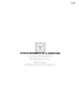
FIG. 1 is a schematic block diagram of a remote starting
system for an engine of a vehicle in accordance with the
for an additional run time period while the engine is still
present invention.
The remote start controller may also be resettable based
65
US 8,258,948 B2
3
4
FIG. 2 is a schematic block diagram of a further embodi
ment of a remote starting system for an engine of a vehicle in
30 and the engine starter 29 may be on the data communica
tions bus 27. Furthermore, each of the security circuit 30 and
the engine starter 29 may communicate unidirectionally via
accordance with the present invention.
FIG. 3 is a schematic block diagram of yet another embodi
the data communications bus 27, or may communicate bidi
ment of a remote starting system for an engine of a vehicle in
rectionally via the data bus. Each of the security circuit 30 and
accordance with the present invention.
FIG. 4 is a schematic block diagram of still another
the engine starter 29 need not communicate in the same
manner via the data communications bus 27. For example, the
embodiment of a remote starting system for an engine of a
security circuit 30 may communicate bidirectionally while
the engine starter 28 communicates unidirectionally.
It should be understood that there may be intervening cir
cuitry, such as a body control module, engine control module,
or powertrain control module, for example, between the data
communications bus 27, the security circuit 30, and/or the
engine starter 29.
The remote starting system 20 illustratively includes a
vehicle in accordance with the present invention.
FIG. 5 is a ?owchart of a method of operating a remote
starting system in accordance with the present invention.
FIG. 6 is a ?owchart of another method of operating a
remote starting system in accordance with the present inven
tion.
FIG. 7 is a schematic block diagram of a remote climate
remote start handheld unit 40 comprising a housing 29. The
housing carries a processor 41 coupled to a transceiver 43, a
control system for a vehicle in accordance with the present
invention.
FIG. 8 is a schematic block diagram of a further embodi
memory 44, a vibration unit 45, a speaker 46, a display 47,
and an input device 48. Further details of the functions of
ment of a remote climate control system for a vehicle in
accordance with the present invention.
FIG. 9 is a schematic block diagram of yet another embodi
20
The remote starting system 20 also includes a transceiver
26 to be positioned at the vehicle 21. In addition, the remote
starting system 20 includes a remote start controller 22 to be
ment of a remote climate control system for a vehicle in
accordance with the present invention.
FIG. 10 is a schematic block diagram of a further embodi
ment of a remote climate control system for a vehicle in
25
FIG. 11 is a ?owchart of a method of operating a remote
DETAILED DESCRIPTION OF THE PREFERRED
EMBODIMENTS
40 causes an engine start signal to be generated on the data
communications bus 27 for operating the engine starter 28,
30
35
The present invention will now be described more fully
40
forms and should not be construed as limited to the embodi
ments set forth herein. Rather, these embodiments are pro
vided so that this disclosure will be thorough and complete,
and will fully convey the scope of the invention to those
skilled in the art. Like numbers refer to like elements through
out, and prime and multiple prime notation are used to indi
which then starts the engine. It should be understood that the
remote start controller 22 itself may not generate the engine
start signal on the data communications bus 27, but instead
may cause an intervening component to generate the engine
start signal on the data communications bus. Of course, in
some applications, the remote start controller 22 may instead
be coupled to the engine starter 28 via the hardwire interface
24, and may operate the engine starter to start the engine 29
via the hardwire interface instead of via the data bus.
hereinafter with reference to the accompanying drawings, in
which preferred embodiments of the invention are shown.
This invention may, however, be embodied in many different
positioned at the vehicle 21 for starting the engine 29 based
upon the remote start handheld unit 40, thereby causing the
engine to run for a run time period before shutting off the
engine 29. To start the engine 29, the remote start controller
accordance with the present invention.
climate control system in accordance with the present inven
tion.
FIG. 12 is a ?owchart of another method of operating a
remote climate control system in accordance with the present
invention.
these components will be given below.
The communications from the remote start handheld unit
40 to the transceiver 26 at the vehicle 21 is typically a direct
radio frequency link. In other words, there are no intervening
communications links. However, in other embodiments, the
remote start handheld unit 40 may indirectly communicate
with the transceiver 26 via other communications infrastruc
45
ture, such a satellite, the public switched telephone network
(PSTN), and/or over the World Wide Web or Internet, as will
be appreciated by those skilled in the art.
cate similar elements in alternative embodiments.
Referring initially to FIG. 1, a remote starting system 20 for
The remote start handheld unit 40 may be a common
an engine 29 of a vehicle 21 is now described. The engine 29
remote transmitter. By common remote transmitter, it is
meant that the remote start handheld unit 40 may operate a
plurality of vehicles 21. Such a feature may be desirable to a
may be an internal combustion engine that burns gasoline,
diesel, ethanol, or other fuels, for example. The vehicle 21
also includes an engine starter 28 for starting the engine 29. In
addition, the vehicle 21 includes a security circuit 30 con
nected to the engine starter 28 to selectively disable the opera
tion thereof and therefore the operation of the engine 29.
Indeed, in some applications, the security circuit 30 may
selectively disable operation of a plurality of, or all of, the
devices and functions of the vehicle 21.
50
driver who owns multiple vehicles 21 or to a rental car com
pany, for example.
The remote start controller 22 may be a multi-vehicle com
55
The vehicle 21 has a data communications bus 27 extend
patible remote start controller that cooperates with the trans
ceiver 26. Those of skill in the art will understand that the
transceiver 26 and the remote start controller 22 may be
associated together in a same housing. In fact the transceiver
26 and the remote start controller 22 may each be embodied
ing throughout. The data communications bus 27 may extend
on a same printed circuit board or even in a same integrated
through the engine compartment, the passenger compart
circuit. The remote start controller 22 illustratively bypasses
the security circuit 30 to enable operation of the engine starter
28 to thereby start the engine 29.
ment, and/ or the trunk of the vehicle 27. The security circuit
30 and the engine starter 28 are each coupled to the data
communications bus 27 for communication thereover. Those
of skill in the art will understand that the security circuit 30
and/ or the engine starter 28 need not be on the data commu
nications bus 27. Indeed, one of, or both of the security circuit
The remote start controller 22 is coupled to the data com
65
munications bus 27 extending within the vehicle 21, via the
bus interface 25, for communication thereover with the secu
rity circuit 30 and engine starter 28. Those skilled in the art
US 8,258,948 B2
5
6
will appreciate that there may be intervening components
in the following references, each of which is incorporated by
reference herein in its entirety, and assigned to the assignee of
between the bus interface 25 and the data communications
bus 27, such as a body control module, engine control mod
the present invention. U.S. Pat. Nos. 7,378,945; 7,369,936;
7,224,083; 7,205,679; 7,091,822; 7,068,153; 7,046,126;
7,031,826; 7,010,402; 6,812,829; 6,756,886; 6,756,885;
6,529,124; 6,346,876; 6,011,460; and 5,719,551.
ule, or powertrain control module. Of course, in some
embodiments, the remote start controller 22 may communi
cate with the security circuit 30 and/or engine starter 28 via a
hardwired connection at the hardwire interface 24. In some
embodiments, the vehicle 21 may not have a data bus 27.
The run time period is resettable based upon the remote
In some embodiments, the remote start controller 22'
implements a timing function executed by a timer 31' of the
processor 23' to send an alert to the remote handheld unit 22'
in the form of a cellular telephone prior to expiration of the
run time period. The processor 41' of the cellular telephone
provides the tactile or audible indication based upon the alert.
In this embodiment, the tactile indication is a pattern of vibra
tions, and the audible indication is a speech message or pat
start handheld unit 40 to cause the engine 29 to run for an
additional run time period, or other time period, while the
engine is still running and before shutting off the engine. That
is, the transceiver 43 of the remote start handheld unit 40 may
be operated by a user to transmit a signal to the remote start
controller 22 instructing it to reset or extend the run time
tern of tones. In some embodiments, the remote start hand
period. This advantageously allows a user to keep the engine
29 running for a greater period of time than the run time
held unit 40' may include a microphone (not shown) for
recording the speech message, and a plurality of songs and/or
speech messages may be stored in the memory 44', each to be
period without the engine being stopped.
If the run time period expires before being reset, the remote
start controller 22 stops the engine. To stop the engine, the
used as a pattern of tones.
20
Other components of the remote starting system 20' are
similar to those described above with reference to FIG. 1.
Those components therefore need no further discussion
herein.
25
(FIG. 3) may provide only a tactile indication through the
remote start controller 22 may cause an engine stop signal to
be generated on the data communications bus 27. It should be
understood that the remote start controller 22 itself may not
generate the engine stop signal on the data communications
bus 27, but instead may cause an intervening component to
In some embodiments, the remote starting system 20"
generate the engine stop signal on the data communications
bus. Of course, in hardwired embodiments, the engine may
also be shut down.
The vibration unit 45 of the remote start handheld unit 40
cooperates with the processor 41 for providing a tactile indi
cation to a user prior to expiration of the run time period.
vibration unit 45", and may not have a speaker. In other
embodiments, the remote starting system 20" (FIG. 4), many
only provide an audible indication through the speaker 46",
30
Additionally or alternatively, the speaker 46 may provide an
audible indication to the user prior to the expiration of the run
time period. This permits the user to use the remote start
handheld unit 40 to reset the run time period while the engine
35
is still running and before shutting off the engine, for example
by entering a command into the input device 48.
The display 47 of the remote start handheld unit 40 may
cooperate with the processor 41 for providing a visual indi
cation to the user prior to expiration of the run time period.
The visual indication may be a countdown until the expiration
of the rune time period, for example.
The processor 41 of the remote start handheld unit 39
includes a timer 49 executing a timing function to operate the
vibration unit 45, and/ or the speaker 46. The pattern of vibra
tions may be settable based upon input received via the input
device 48. Of course, the speech message or pattern of tones
may also be settable based upon input receives via the input
device 48.
With reference to FIG. 2, an alternative embodiment of the
started based upon a remote start handheld unit and caused to
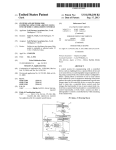
At Block 53, an alert is sent to the remote start handheld
unit prior to expiration of the run time period. At Block 54, a
40
45
50
55
signal received over the data communications bus 27' from
another component.
60
described. After the start (Block 61), at Block 62, the vehi
to use the remote start handheld unit to reset the run time
period by sending a reset run time period signal.
it is meant that the remote start controller 22' may be able to
communicate with other devices on the data bus 27' using a
desired set of codes from among a plurality of different sets of
multi-vehicle compatible devices and operation may be found
the remote start handheld unit to reset the run time period by
sending a reset run time period signal.
If a reset run time period signal is not received at Block 55,
the engine is shut off at Block 57. If a reset run time period
signal is received from the remote start handheld unit at Block
55, the engine is caused to run for an additional run time
period at Block 56. At this point, an alert is again sent to the
remote start handheld unit prior to expiration of the run time
period at Block 53 again. The steps repeat until a reset run
time period signal is not received from the remote start hand
held unit at Block 55. At this point, the engine is shut off at
Block 57. Block 58 indicates the end of the method.
With reference to the ?owchart 60 of FIG. 6, another
method of operating a remote starting system is now
prior to expiration of the rune time period, to permit the user
In addition, in this embodiment, the remote start controller
codes for different vehicles or vehicle platforms.
In other words, the same remote start controller 22' may be
installed in a variety of different vehicles. More details of
tactile indication is provided to a user to permit the user to use
cle’ s engine is started based upon a remote start handheld unit
and caused to run for a run time period.
At Block 63, an audible indication is provided to a user,
connected to the remote start controller 22', or based upon a
22' is multi-vehicle compatible. By multi-vehicle compatible,
After the start (Block 51), at Block 52, the vehicle’s engine is
run for a run time period.
remote start controller 22' is now described. In this embodi
ment, the remote start handheld unit 40' comprises a cellular
telephone. In addition, the run time period is settable, for
example based upon the cellular telephone 40'. The run time
period may also be settable based upon a switch (not shown)
and may not have a vibration unit. Other components of the
remote starting systems 20", 20" are similar to those
described above with reference to FIG. 2. Those components
therefore need no further discussion herein.
With reference to the ?owchart 50 of FIG. 5, a method of
operating a remote starting system in a vehicle is described.
65
If a reset run time period signal is not received at Block 64,
the engine is shut off at Block 66. If a reset run time period
signal is received from the remote start handheld unit at Block
64, the engine is caused to run for an additional run time
period at Block 65. At this point, an audible indication is again
provided to the user at Block 63. The steps repeat until a reset
US 8,258,948 B2
7
8
run time period signal is not received from the remote start
handheld unit at Block 64. At this point, the engine is shut off
at Block 66. Block 67 indicates the end of the method.
Referring now to FIG. 7, another embodiment of a remote
climate control system 120 for a vehicle 121 isH now
cally powered climate control system 132. Those of skill in
the art will appreciate that, in some applications, the security
circuit 130 may also be connected to the engine starter 128 to
selectively disable the operation thereof and therefore the
operation of the engine 129. Indeed, in some applications, the
security circuit 130 may selectively disable operation of a
plurality of, or all of, the devices and functions of the hybrid
described. The vehicle 121 has a rechargeable battery 135,
although those of skill in the art will appreciate that the
vehicle may have another rechargeable electrical power
vehicle 121.
The vehicle 121 has a data communications bus 127
source. The vehicle 121 has an electric motor 136 electrically
powered by the rechargeable battery 135. Skilled artisans will
extending throughout. The data communications bus 127
may extend through the engine compartment, the passenger
appreciate that there may be more than one electric motor 13 6
and more than one rechargeable battery 135. In some embodi
compartment, and/ or the trunk of the vehicle 121.
The sensor 134 is coupled to the rechargeable battery 135
and reads the voltage thereof. The sensor 134 may, addition
ments, the vehicle 121 is a hybrid vehicle and has an engine
129 that operates a generator or alternator (not shown) to
recharge the rechargeable battery 135 and/or power the elec
ally or alternatively, be able to detect whether the recharge
tric motor 136. An optional separate engine starter 128 starts
the engine 129. Those of skill in the art will understand that
the engine 129 may instead be started by the electric motor
able battery is connected to an external power source 137. The
136.
It should be understood that the engine 129 may be an
external power source 137 may be an electrical socket or
recharging station, for example.
The electrically powered climate control system 132, the
20
internal combustion engine that burns gasoline, diesel, etha
are each coupled to the data communications bus 127 for
communication thereover. Those of skill in the art will under
nol, or other fuels. Rather than an internal combustion engine
129, the vehicle 121 may instead have an external heat engine,
such as a Stirling engine.
The vehicle 121 further comprises an electrically powered
stand that each of the electrically powered climate control
system 132, the sensor 134, the security circuit 130, and the
25
climate control system 132 selectively powered by the
engine starter 128 need not be on the data communications
bus 127. Indeed, one of, or a plurality of electrically powered
climate control system 132, the sensor 134, the security cir
cuit 130, and the engine starter 128 may be on the data
communications bus 127. Furthermore, each of the electri
rechargeable battery 135 and a sensor 134 associated with the
rechargeable battery. By electrically powered climate control
system 135, it is means that the climate control system is not
driven by mechanical power from the engine 129 and instead
receives electrical power from the rechargeable battery 135 or
sensor 134, the security circuit 130, and the engine starter 128
30
cally powered climate control system 132, the sensor 134, the
security circuit 130, and the engine starter 128 may commu
an alternator/generator (not shown) coupled to the engine
129. Alternatively, the electrically powered climate control
nicate unidirectionally via the data communications bus 127,
system 135 may receive mechanical power from a motor (not
tion, each of the electrically powered climate control system
132, the sensor 134, the security circuit 130, and the engine
shown) coupled to the rechargeable battery 135 or an alter
or may communicate bidirectionally via the data bus. In addi
35
nator/generator (not shown) coupled to the engine 129, but
starter 128 need not communicate in the same manner via the
not from the engine itself.
data communications bus 127. For example, the electrically
powered climate control system 132 may communicate bidi
The electrically powered climate control system 132 may
include an electrical ventilation blower, an electrical heater,
and/or an electrically powered AC compressor. A suitable
electrical ventilation blower may be a conventional blower
rectionally while the sensor 134 communicates unidirection
40
ally.
45
It should be understood that there may be intervening cir
cuitry, such as a body control module, engine control module,
or powertrain control module, between the electrically pow
ered climate control system 132, the sensor 134, the security
circuit 130, and/or the engine starter 128.
50
start handheld unit 140 comprising a housing 129. The hous
ing carries a processor 141 coupled to a transceiver 143, a
memory 144, a vibration unit 145, a speaker 146, a display
147, and an input device 148. Further details of the functions
coupled to an electric motor via a belt or may be a blower
having an internal electric motor. It should be understood that
such an electrical ventilation blower merely blows ambient
outside air into the passenger compartment of the vehicle 121
and does not actively cool the air, as would an electrically
powered AC unit. It may be advantageous to use an electrical
ventilation blower to cool the passenger compartment of the
vehicle 121 as opposed to an electrical AC unit because the
electrical ventilation blower may consume less electricity
The remote climate control system 120 includes a remote
of these components will be given below.
than an electrical AC unit.
A suitable electrical heater may be a resistive heater or
other suitable heater as known to those of skill in the art. In
addition, a suitable electrical heater may be a combination
The remote climate control system 120 includes a trans
ceiver 126 to be positioned at the vehicle 121. In addition, the
remote climate control system 120 includes a remote climate
heater, for example a heater core with electrical heater coils,
which employs both resistive heating and the use of waste
heat from the engine 129 to heat the passenger compartment
of the vehicle 121.
A suitable electrically powered AC unit may be a conven
55
tional AC compressor coupled to an electric motor via a belt
or may be an AC compressor having an internal electric
motor. In some embodiments, the electrical AC unit may be a
thermoelectric cooler or other suitable electric AC unit as
known to those of skill in the art.
60
The vehicle 121 may also include a security circuit 130
65
connected to the electrically powered climate control system
132. The security circuit 130 selectively disables the electri
controller 122 to be positioned at the vehicle 121 for starting
the electrically powered climate control system 132 based
upon the remote climate control handheld unit 140, thereby
causing the electrically powered climate control system 132
to run for a run time period before shutting off the electrically
powered climate control system 132.
The remote climate control handheld unit 140 may cause
the remote climate controller 122 to heat the passenger com
partment of the vehicle 121 to a pre-set temperature. Altema
tively, the remote climate control handheld unit 140 may have
buttons that enable a user to set the temperature to which the
remote climate controller 122 is to heat the passenger com
partment of the vehicle 121. Additionally or alternatively, the
US 8,258,948 B2
10
132. That is, the transceiver 143 of the remote climate control
handheld unit 140 may transmit a signal to the remote climate
remote climate control handheld unit 140 may have buttons
(input device 148) that enable a user to select to which of a
plurality of pre- set temperatures the remote climate controller
122 is to heat the passenger compartment of the vehicle 121.
controller 122 instructing it to reset or extend the run time
period. This advantageously allows a user to keep the electri
132, the remote climate controller 140 causes a climate con
cally powered climate control system 132 running for a
greater period of time than the run time period without the
trol start signal to be generated on the data communications
electrically powered climate control system being stopped.
bus 127 for operating the electrically powered climate control
If the run time period expires before being reset, the remote
climate controller 122 stops the electrically powered climate
control system 132. To stop the electrically powered climate
To start the electrically powered climate control system
system 132. It should be understood that the remote climate
controller 122 itself may not generate the climate control start
signal on the data communications bus 127, but instead may
control system 132, the remote climate controller 122 may
cause a climate control stop signal to be generated on the data
communications bus 127. It should be understood that the
remote climate controller 122 itself may not generate the
climate control stop signal on the data communications bus
127, but instead may cause an intervening component to
generate the climate control stop signal on the data commu
nications bus.
The vibration unit 145 of the remote climate control hand
cause an intervening component to generate the climate con
trol start signal on the data communications bus.
The communications from the remote climate control
handheld unit 140 to the transceiver 126 at the vehicle 121 are
typically a direct radio frequency link. In other words, there
are no intervening communications links. However, in other
embodiments, the remote climate control handheld unit 140
may indirectly communicate with the transceiver 126 via
other communications infrastructure, such a satellite, the
public switched telephone network (PSTN), and/ or over the
World Wide Web or Internet, as will be appreciated by those
20
a tactile indication to a user prior to expiration of the run time
period. Additionally or alternatively, the speaker 146 may
skilled in the art.
The remote climate control handheld unit 140 may also
include one or more central station transmitters, such as may 25
30
example.
the expiration of the run time period, for example.
35
compatible remote climate controller that cooperates with the
transceiver 126. Those of skill in the art will understand that
the transceiver 126 and the remote climate controller 122 may
be associated together in a same housing. In fact the trans
ceiver 26 and the remote climate controller 122 may each be
40
embodied on a same printed circuit board or even in a same
integrated circuit. The remote climate controller 122
control handheld unit 140. For example, the remote climate
controller 122 may operate the electrically powered climate
control system 132 for the run time period if it receives, via
the transceiver 126, a signal from the remote climate control
handheld unit 140 instructing it to do so.
50
If, during operation of the electrically powered climate
control system 132, the sensor 134 senses that the voltage of
the rechargeable battery 135 has fallen below a threshold
voltage, the remote climate controller 122 may disable the
electrically powered climate control system to conserve the
intervening components between the bus interface 125 and
the data communications bus 127, such as a body control
operate the vibration unit 145 and the speaker 146. The pat
tern of vibrations may be settable based upon input received
via the input device 148. Of course, the speech message or
pattern of tones may also be settable based upon input
receives via the input device 148.
As stated above, the remote climate controller 122 selec
tem 132 responsive to the sensor 134 and the remote climate
45
communications bus 127 extending within the vehicle 121,
via the bus interface 115, for communication thereover with
the security circuit 130 and optional engine starter 128. The
bus interface 115 includes circuitry for interfacing to the
proper signal levels and formats on the data communications
bus 127 as will be appreciated by those skilled in the art
without further discussion herein.
Those skilled in the art will appreciate that there may be
The processor 141 of the remote climate control handheld
unit 139 includes a timer 49 executing a timing function to
tively operates the electrically powered climate control sys
bypasses the security circuit 30 to enable operation of the
electrically powered climate control system 132.
The remote climate controller 122 is coupled to the data
ered climate control system, for example by entering a com
mand into the input device 148.
The display 147 of the remote climate control handheld
unit 140 may cooperate with the processor 141 for providing
a visual indication to the user prior to expiration of the run
time period. The visual indication may be a countdown until
owns multiple vehicles 121 or to a rental car company, for
The remote climate controller 122 may be a multi-vehicle
provide an audible indication to the user prior to the expira
tion of the rune time period. This permits the user to use the
remote climate control handheld unit 140 to reset the run time
period while the electrically powered climate control system
is still running and before shutting off the electrically pow
be provided by a satellite transmitter, for example. Such a
central station transmitter may also be connected to other
communications infrastructures. The remote climate control
handheld unit 140 may be a common remote transmitter. By
common remote transmitter, it is meant that the remote cli
mate control handheld unit 140 may operate a plurality of
vehicles 121. Such a feature may be desirable to a driver who
held unit 140 cooperates with the processor 141 for providing
55
voltage of the rechargeable battery. Similarly, if the remote
module, engine control module, or powertrain control mod
climate controller 122 receives an instruction to activate the
ule. Of course, in some embodiments, the remote climate
electrically powered climate control system 132, but the sen
controller 122 may communicate with the security circuit 130
and/ or optional engine starter 128 via a hardwired connection
at the hardwire interface 124. In fact, in some embodiments,
sor 134 senses that the voltage of the rechargeable battery 135
is below a threshold voltage, the remote climate controller
60
the vehicle 121 may not have a data bus 127.
The run time period is resettable based upon the remote
climate control handheld unit 140 to cause the electrically
powered climate control system 132 to run for an additional
run time period, or other time period, while the electrically
powered climate control system is still running and before
shutting off the electrically powered climate control system
65
122 may not activate the electrically powered climate control
system. This feature helps to prevent excessive discharging of
the rechargeable battery 135, due to operation of the electri
cally powered climate control system 132, that might leave a
driver stranded and the vehicle 121 inoperable.
If, during operation of the electrically powered climate
control system 132, the sensor 134 senses that the voltage of
the rechargeable battery 135 has fallen below a threshold
US 8,258,948 B2
11
12
voltage, the remote climate controller 122 may start the
In addition, in this embodiment, the remote climate con
troller 122' is multi-vehicle compatible. That is, the same
remote climate controller 122' may be installed in a variety of
vehicles.
engine 129 (if there is one). This may be done to charge the
rechargeable battery 135 and to help prevent excessive dis
charging thereof.
In addition, here, remote climate controller 122' imple
If the remote climate controller 122 receives an instruction
to activate the electrically powered climate control system
ments a timing function executed by a timer 131' of the
processor 123' to send an alert to the cellular telephone 122'
132, but the sensor 134 senses that the voltage of the recharge
able battery 135 is below a threshold voltage, the remote
climate controller 122 may start the engine 129 (if there is
prior to expiration of the run time period. The processor 141'
of the cellular telephone 122' provides the tactile or audible
indication based upon the alert. In this embodiment, the tac
tile indication is a pattern of vibrations, and the audible indi
one) prior to operating the electrically powered climate con
trol system 132.
In some applications, the remote climate controller 122
may sense if the shift selector of the vehicle 121 is in a
cation is a speech message or pattern of tones. In some
position other than park and, if so, the remote climate con
troller may not start the engine 129. Similarly, the remote
may include a microphone (not shown) for recording the
climate controller 122 may sense whether the hood of the
vehicle 121 is open and may not start the engine 129 based
memory 144', each to be used as a pattern of tones.
thereupon. In addition, the remote climate controller 122 may
shut down the engine 129 if the engine RPM exceeds a pre
determined value. Many other vehicle conditions, such as the
fuel level of the vehicle 121 (either fossil fuel, or a substance
consumed by the rechargeable battery if it is a fuel cell) may
be taken into account by the remote climate controller 122
before or during operation of the engine 129 as will be appre
120' are similar to those described above with reference to
FIG. 7. Those components therefore need no further discus
ciated by those skilled in the art. If the remote climate con
troller 122 elects to not start, or elects to shut down, the engine
129 due to such a vehicle condition, it may instead deactivate
embodiments, the remote climate control handheld unit 140'
speech message, and a plurality of songs may be stored in the
Other components of the remote climate control system
20
120" (FIG. 9) may provide only a tactile indication through
the vibration unit 145", and may not have a speaker. In other
25
the electrically powered climate control system 132.
The remote climate controller 122 may enable the electri
cally powered climate control system 132 based upon the
sensor 134 sensing the rechargeable battery 135 being
30
coupled to an external power source 137. The external power
source 137 may be an electrical socket, a recharging station,
speaker 146", and may not have a vibration unit. Other com
ponents of the remote climate control systems 120", 120" are
similar to those described above with reference to FIG. 2.
Those components therefore need no further discussion
herein.
With reference to the ?owchart 150 of FIG. 11, a method of
operating a remote climate control system in a vehicle is
described. After the start (Block 151), at Block 152, the
35
In some applications, the vehicle 121 may have a solar
started based upon a remote climate control handheld unit and
caused to run for a run time period.
panel, such as on the roof thereof, coupled to the rechargeable
battery 135. The remote climate controller 122 may also
enable the electrically powered climate control system 132
based upon the sensor 134 sensing the rechargeable battery
embodiments, the remote climate control system 120" (FIG.
10), many only provide an audible indication through the
vehicle’s electrically powered climate control system is
or other external power source as known to those skilled in the
art.
sion herein.
In some embodiments, the remote climate control system
At Block 153, an alert is sent to the remote climate control
handheld unit prior to expiration of the run time period. At
Block 154, a tactile indication is provided to a user to permit
40
the user to use the remote climate control handheld unit to
135 being recharged by the solar panel.
reset the run time period by sending a reset run time period
Those of skill in the art will appreciate that the sensor 134
may also measure the current ?owing in of or out of the
signal.
rechargeable battery 135 and that the remote climate control
ler 122 may operate the electrically powered climate control
the electrically powered climate control system is shut off at
If a reset run time period signal is not received at Block 155,
45
system 132 based thereupon in the same manner as described
above with reference to voltages of the rechargeable battery.
Similarly, the sensor 134 may measure the temperature of the
rechargeable battery 135 and the remote climate controller
122 may also operate the electrically powered climate control
50
system 132 based thereupon in the same manner as described
above with reference to the voltage of the rechargeable bat
tery 135.
In some applications, the remote climate controller 122
may operate the window motor 133 while it runs the electri
At this point, the electrically powered climate control system
55
cally powered climate control system 132. This may advan
tageously help cool the passenger compartment of the vehicle
121 more quickly.
With reference to FIG. 8, an alternative embodiment of the
remote climate controller 122' is now described. In this
embodiment, the remote climate control handheld unit 140'
comprises a cellular telephone. In addition, the run time
controller 122', or based upon a signal received over the data
communications bus 127' from another component.
is shut off at Block 157. Block 158 indicates the end of the
method.
With reference to the ?owchart 160 of FIG. 6, another
method of operating a remote climate control system is now
described. After the start (Block 161), at Block 162, the
vehicle’s electrically powered climate control system is
60
started based upon a remote climate control handheld unit and
caused to run for a run time period.
At Block 163, an audible indication is provided to a user,
period is settable, for example based upon the cellular tele
phone 140'. The run time period may also be settable based
upon a switch (not shown) connected to the remote climate
Block 15. If a reset run time period signal is received from the
remote climate control handheld unit at Block 155, the elec
trically powered climate control system is caused to run for an
additional run time period at Block 156. At this point, an alert
is again sent to the remote climate control handheld unit prior
to expiration of the run time period at Block 153 again. The
steps repeat until a reset run time period signal is not received
from the remote climate control handheld unit at Block 155.
prior to expiration of the rune time period, to permit the user
to use the remote climate control handheld unit to reset the run
65
time period by sending a reset run time period signal.
If a reset run time period signal is not received at Block 164,
the electrically powered climate control system is shut off at