1
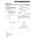
US008823654B2
(12) United States Patent
(10) Patent N0.:
(45) Date of Patent:
Jeong et a1.
(54)
MOBILE TERMINAL AND CONTROLLING
METHOD THEREOF
(75) Inventors: Kye Sook Jeong, Seoul (KR); Jung Ok
Cho, Seoul (KR); Seung Hyun Yang,
Seoul (KR); Hee Young Cho, Seoul
(KR)
Notice:
2007/0101340 A1*
2008/0256477
2008/0261660
2009/0141024
2009/0244023
2010/0088598
Subject to any disclaimer, the term of this
patent is extended or adjusted under 35
Yang ........................ .. 455/414.1
EP
2071145
6/2009
mons to Attend Oral Proceedings dated Mar. 19, 2013, 7 pages.
Feb. 17, 2011
* cited by examiner
Foreign Application Priority Data
Aug. 11, 2009
4/2010
715/772
455/566
345/420
345/173
715/704
Apple Inc., “iPhone 3G User Manual,” Jul. 2008, XP-007907619.
European Patent Of?ce Application Serial No. 100079425, Sum
Prior Publication Data
(30)
Yoo ............................. .. 718/107
Apple Inc., “Apple Human Interface GuidelinesiUser Experience,”
Sep. 2008, XP-007906962.
May 4, 2010
US 2011/0037710A1
5/2007
OTHER PUBLICATIONS
(21) Appl.No.: 12/773,791
(65)
6/2006 Fukuta
12/2006 Bystricky et al.
3/2007 Toyama et a1.
FOREIGN PATENT DOCUMENTS
U.S.C. 154(b) by 448 days.
(22) Filed:
Sep. 2, 2014
A1* 10/2008 Cho et al.
A1* 10/2008 Huh et al.
A1* 6/2009 Lee et al.
A1* 10/2009 Kim et a1.
A1* 4/2010 Lee et al.
2010/0105364 A1*
(73) Assignee: LG Electronics Inc., Seoul (KR)
(*)
2006/0120692 A1
2006/0288299 A1
2007/0047909 A1
US 8,823,654 B2
Primary Examiner * Quan-Zhen Wang
(KR) ...................... .. 10-2009-0073783
Assistant Examiner * Tony Davis
(74) Attorney, Agent, or Firm * Lee, Hong, Degerman,
(51)
Kang & Waimey
Int. Cl.
(2006.01)
G06F 3/041
(57)
(52) US. Cl.
USPC
(58)
........................................................ ..
345/173
Field of Classi?cation Search
CPC G06F 3/04817; G11B 19/025; G11B 27/105;
G11B 27/34; H04M1/72522; H04M1/72558;
H04M 2250/22
USPC .......................... .. 715/863; 345/173; 718/107
See application ?le for complete search history.
(56)
References Cited
U.S. PATENT DOCUMENTS
8,082,523 B2 *
2001/0040571 A1*
12/2011
11/2001
Forstall et al. .............. .. 715/863
Miller ......................... .. 345/419
2003/0112279 A1
6/2003 Irimajiri
2003/0119562 A1
6/2003 Kokubo
ABSTRACT
A mobile terminal and controlling method thereof are dis
closed, Which facilitates a terminal to be used in further con
sideration of user’s convenience. According to at least one of
embodiments of the present invention, While a ?rst function is
being executed in a mobile terminal, if a second function
different from the ?rst function is executed, a ?rst function
icon having execution progress status information of the ?rst
function at a timing point of stopping the execution of the ?rst
function can be generated. If the ?rst function is re-executed
by selecting the ?rst function icon later, it is advantageous in
that the ?rst function can be executed in a manner of being
continuous With an execution progress status at the execution
stop timing point.
13 Claims, 12 Drawing Sheets
US. Patent
Sep.2,2014
US 8,823,654 B2
Sheet10f12
xi “
53:2 *
W
\m“
...
u.
...
U S. Patent
Sep.2,2014
Sheet20f12
§§
US 8,823,654 B2
US. Patent
Sep.2,2014
Sheet30f12
3.
w --------------\----------“\\
US 8,823,654 B2
U S. Patent
Sep.2,2014
US 8,823,654 B2
Sheet40f12
1S:. .
“
:\. \
U S. Patent
Sep. 2, 2014
Sheet 5 0f 12
.....4....\\\>.
US 8,823,654 B2
U S. Patent
Sep. 2, 2014
Sheet 6 0f 12
US 8,823,654 B2
U S. Patent
Sep. 2, 2014
Sheet 7 0f 12
.\
US 8,823,654 B2
\..“...“.““......‘...........um.mmw
US. Patent
Sep. 2, 2014
Sheet 8 0f 12
231-4
US 8,823,654 B2
U S Patent
Sep.2,2014
Sheet90f12
US 8,823,654 B2
US. Patent
Sep. 2, 2014
Sheet100f12
US 8,823,654 B2
U S. Patent
Sep. 2, 2014
Sheet 11 0112
US 8,823,654 B2
U S Patent
Sep. 2, 2014
Sheet120f12
US 8,823,654 B2
US 8,823,654 B2
1
2
MOBILE TERMINAL AND CONTROLLING
METHOD THEREOF
skill in the art upon examination of the following or may be
learned from practice of the invention. The objectives and
other advantages of the invention may be realized and
attained by the structure particularly pointed out in the written
description and claims hereof as well as the appended draw
Pursuant to 35 U.S.C. §l 19(a), this application claims the
bene?t of earlier ?ling date and right of priority to Korean
Application No. 10-2009-0073783, ?led on Aug. 11, 2009,
the contents of which are hereby incorporated by reference
herein in their entirety.
ings.
To achieve these objects and other advantages and in accor
dance with the purpose of the invention, as embodied and
broadly described herein, a mobile terminal according to the
BACKGROUND OF THE INVENTION
present invention includes a touchscreen, and a controller is
con?gured to, after a ?rst function has been executed such
that a ?rst function window is being displayed on the touch
screen, if a second function is newly executed, render the ?rst
1. Field of the Invention
The present invention relates to a mobile terminal, and
more particularly, to a mobile terminal and controlling
function window to disappear by stopping the execution of
method thereof. Although the present invention is suitable for
a wide scope of applications, it is particularly suitable for
facilitating a terminal to be used in further consideration of
user’s convenience.
2. Discussion of the RelatedArt
A mobile terminal is a device which may be con?gured to
the ?rst function automatically, and display a ?rst function
icon having execution progress status information of the ?rst
function at an execution stop timing point of the ?rst function
on the touchscreen.
20
perform various functions. Examples of such functions
include data and voice communications, capturing images
and video via a camera, recording audio, playing music ?les
and outputting music via a speaker system, and displaying
images and video on a display. Some terminals include addi
tion includes displaying a ?rst function window on a touch
screen when a ?rst function is executed, newly executing a
second function in the course of executing the ?rst function,
automatically stopping the execution of the ?rst function,
25
tional functionality which supports game playing, while other
terminals are also con?gured as multimedia players. More
rendering the ?rst function window to disappears, and dis
playing a ?rst function icon having execution progress status
information of the ?rst function at an execution stop timing
point of the ?rst function on the touchscreen.
It is to be understood that both the foregoing general
recently, mobile terminals have been con?gured to receive
broadcast and multicast signals which permit viewing of con
tents, such as videos and television programs.
Generally, terminals can be classi?ed into mobile termi
nals and stationary terminals according to a presence or non
In another aspect of the present invention, a method of
controlling a mobile terminal according to the present inven
30
description and the following detailed description of the
present invention are exemplary and explanatory and are
intended to provide further explanation of the invention as
claimed.
presence of mobility. And, the mobile terminals canbe further
classi?ed into handheld terminals and vehicle mount termi
nals according to availability for hand-carry.
There are ongoing efforts to support and increase the func
tionality of mobile terminals. Such efforts include software
and hardware improvements, as well as changes and improve
ments in the structural components which form the mobile
terminal.
35
The accompanying drawings, which are included to pro
vide a further understanding of the invention and are incor
porated in and constitute a part of this application, illustrate
40
Recently, mobile terminals capable of performing multi
tasking functionality for executing at least two functions are
ongoing to be released.
However, when at least two functions are simultaneously
executed in a mobile terminal, the multitasking occasionally
fails to be smoothly executed due to the restricted perfor
embodiment(s) of the invention and together with the descrip
tion serve to explain the principle of the invention. In the
drawings:
45
FIG. 1 is a block diagram of a mobile terminal according to
one embodiment of the present invention;
FIG. 2A is a front perspective diagram of a mobile terminal
according to one embodiment of the present invention;
FIG. 2B is a rear perspective diagram of a mobile terminal
mance of the mobile terminal. Therefore, while one function
is being executed in the mobile terminal, if another function is
according to one embodiment of the present invention;
executed, many efforts need to be further made to research
and develop how to process the formerly executed function in
consideration of terminal user’s convenience.
BRIEF DESCRIPTION OF THE DRAWINGS
FIG. 3 is a ?owchart for a method of controlling a mobile
50
terminal according to an embodiment of the present inven
tion; and
FIGS. 4 to 12 are diagrams for con?gurations of a display
SUMMARY OF THE INVENTION
Accordingly, the present invention is directed to a mobile
screen on which a method of controlling a mobile terminal
55
according to an embodiment of the present invention is imple
mented.
terminal and controlling method thereof that substantially
DETAILED DESCRIPTION OF THE INVENTION
obviate one or more problems due to limitations and disad
vantages of the related art.
An object of the present invention is to provide a mobile
terminal and controlling method thereof. While one function
is being executed in the mobile terminal, if another function is
Reference will now be made in detail to the preferred
tion will be set forth in part in the description which follows
embodiments of the present invention, examples of which are
illustrated in the accompanying drawings. It is to be under
stood by those of ordinary skill in this technological ?eld that
other embodiments may be utilized, and structural, electrical,
as well as procedural changes may be made without departing
from the scope of the present invention. Wherever possible,
the same reference numbers will be used throughout the
and in part will become apparent to those having ordinary
drawings to refer to the same or like parts.
60
executed, the present invention enables the formerly executed
function to be properly processed in consideration of further
enhancement of terminal user’s convenience.
Additional advantages, objects, and features of the inven
65
US 8,823,654 B2
3
4
As used herein, the suf?xes ‘module’, ‘unit’ and ‘part’ are
used for elements in order to facilitate the disclosure only.
Therefore, signi?cant meanings or roles are not given to the
suf?xes themselves and it is understood that the ‘module’,
‘unit’ and ‘part’ can be used together or interchangeably.
tal multimedia broadcasting (DMB) and electronic service
guide (ESG) of digital video broadcast-handheld (DVB-H).
The broadcast receiving module 111 may be con?gured to
receive broadcast signals transmitted from various types of
broadcast systems. By nonlimiting example, such broadcast
ing systems include digital multimedia broadcasting-terres
trial (DMB-T), digital multimedia broadcasting-satellite
(DMB-S), digital video broadcast-handheld (DVB-H), DVB
CBMS, OMA-BCAST, the data broadcasting system known
The present invention can be applicable to a various types
of terminals. Examples of such terminals include mobile as
well as stationary terminals, such as mobile phones, user
equipment, smart phones, DTV, computers, digital broadcast
terminals, personal digital assistants, portable multimedia
players (PMP) and navigators.
However, by way of non-limiting example only, further
as media forward link only (MediaFLO®) and integrated
services digital broadcast-terrestrial (ISDB-T). Optionally,
the broadcast receiving module 111 can be con?gured suit
able for other broadcasting systems as well as the above
description will be with regard to a mobile terminal 100, and
it should be noted that such teachings may apply equally to
other types of terminals.
explained digital broadcasting systems.
The broadcast signal and/ or broadcast associated informa
FIG. 1 is a block diagram of a mobile terminal 100 in
accordance with an embodiment of the present invention.
FIG. 1 shows the mobile terminal 100 according to one
embodiment of the present invention includes a wireless com
munication unit 110, an A/V (audio/video) input unit 120, a
user input unit 130, a sensing unit 140, an output unit 150, a
tion received by the broadcast receiving module 111 may be
stored in a suitable device, such as a memory 160.
20
base station, external terminal, server, etc.). Such wireless
signals may represent audio, video, and data according to
text/multimedia message transceivings, among others.
memory 160, an interface unit 170, a controller 180, a power
supply unit 190 and the like. FIG. 1 shows the mobile terminal
100 having various components, but it is understood that
implementing all of the illustrated components is not a
requirement. Greater or fewer components may alternatively
25
be implemented.
In the following description, the above elements of the
30
includes one or more components which permits wireless
communication between the mobile terminal 100 and a wire
less communication system or network within which the
mobile terminal 100 is located. For instance, the wireless
communication unit 110 can include a broadcast receiving
module 111, a mobile communication module 112, a wireless
internet module 113, a short-range communication module
114, a position-location module 115 and the like.
The broadcast receiving module 111 receives a broadcast
signal and/or broadcast associated information from an exter
nal broadcast managing server via a broadcast channel.
The broadcast channel may include a satellite channel and
Interoperability for Microwave Access), HSDPA (High
Speed Downlink Packet Access), etc.
The short-range communication module 114 facilitates
35
relatively short-range communications. Suitable technolo
gies for implementing this module include radio frequency
identi?cation (RFID), infrared data association (IrDA), ultra
wideband (UWB), as well at the networking technologies
commonly referred to as Bluetooth and ZigBee, to name a
40
few.
The position-location module 115 identi?es or otherwise
obtains the location of the mobile terminal 1 00. If desired, this
45
module may be implemented with a global positioning sys
tem (GPS) module.
Referring to FIG. 1, the audio/video (A/V) input unit 120 is
con?gured to provide audio or video signal input to the
mobile terminal 100. As shown, the A/V input unit 120
a terrestrial channel.
The broadcast managing server generally refers to a server
which generates and transmits a broadcast signal and/or
The wireless internet module 113 supports Internet access
for the mobile terminal 100. This module may be internally or
externally coupled to the mobile terminal 100. In this case, the
wireless Internet technology can include WLAN (Wireless
LAN) (Wi-Fi), Wibro (Wireless broadband), Wimax (World
mobile terminal 100 are explained in sequence.
First of all, the wireless communication unit 110 typically
The mobile communication module 112 transmits/receives
wireless signals to/from one or more network entities (e.g.,
broadcast associated information or a server which is pro
includes a camera 121 and a microphone 122. The camera 121
vided with a previously generated broadcast signal and/or
receives and processes image frames of still pictures or video,
broadcast associated information and then transmits the pro
vided signal or information to a terminal. The broadcast sig
nal may be implemented as a TV broadcast signal, a radio
broadcast signal, and a data broadcast signal, among others. If
desired, the broadcast signal may further include a broadcast
signal combined with a TV or radio broadcast signal.
At least two broadcast receiving modules 111 can be pro
vided to the mobile terminal 100 in pursuit of simultaneous
receptions of at least two broadcast channels or broadcast
which are obtained by an image sensor in a video call mode or
50
stored in the memory 160 or can be externally transmitted via
the wireless communication unit 110. Optionally, at least two
cameras 121 can be provided to the mobile terminal 100
55
channel switching facilitation.
audio signal is processed and converted into electric audio
60
tion may include an electronic program guide (EPG) of digi
data. The processed audio data is transformed into a format
transmittable to a mobile communication base station via the
mobile communication module 112 in case of a call mode.
associated information can be provided via a mobile commu
nication network. In this case, the broadcast associated infor
mation can be received by the mobile communication module
112.
The broadcast associated information can be implemented
in various forms. For instance, broadcast associated informa
according to environment of usage.
The microphone 122 receives an external audio signal
while the portable device is in a particular mode, such as
phone call mode, recording mode and voice recognition. This
The broadcast associated information includes informa
tion associated with a broadcast channel, a broadcast pro
gram, a broadcast service provider, etc. And, the broadcast
a photographing mode. And, the processed image frames can
be displayed on the display 151.
The image frames processed by the camera 121 can be
The microphone 122 typically includes assorted noise remov
ing algorithms to remove noise generated in the course of
65
receiving the external audio signal.
The user input unit 130 generates input data responsive to
user manipulation of an associated input device or devices.
US 8,823,654 B2
5
6
Examples of such devices include a keypad, a dome switch, a
output device. In this case, the touch sensor can be con?gured
as a touch ?lm, a touch sheet, a touchpad or the like.
touchpad (e. g., static pressure/ capacitance), a jog wheel, a jog
The touch sensor can be con?gured to convert a pressure
switch, etc.
applied to a speci?c portion of the display 151 or a variation
The sensing unit 140 provides sensing signals for control
of a capacitance generated from a speci?c portion of the
display 151 to an electric input signal. Moreover, it is able to
ling operations of the mobile terminal 100 using status mea
surements of various aspects of the mobile terminal. For
instance, the sensing unit 140 may detect an open/ close status
of the mobile terminal 100, relative positioning of compo
nents (e.g., a display and keypad) of the mobile terminal 100,
con?gure the touch sensor to detect a pressure of a touch as
well as a touched position or size.
If a touch input is made to the touch sensor, signal(s)
corresponding to the touch is transferred to a touch controller.
a change of position of the mobile terminal 100 or a compo
nent of the mobile terminal 100, a presence or absence of user
The touch controller processes the signal(s) and then transfers
the processed signal(s) to the controller 180. Therefore, the
contact with the mobile terminal 100, orientation or accelera
tion/ deceleration of the mobile terminal 100. As an example,
consider the mobile terminal 100 being con?gured as a slide
controller 180 is able to know whether a prescribed portion of
the display 151 is touched.
Referring to FIG. 1, a proximity sensor (not shown in the
type mobile terminal. In this con?guration, the sensing unit
drawing) can be provided to an internal area of the mobile
terminal 100 enclosed by the touchscreen or around the
140 may sense whether a sliding portion of the mobile termi
nal is open or closed. Other examples include the sensing unit
touchscreen. The proximity sensor is the sensor that detects a
presence or non-presence of an object approaching a pre
140 sensing the presence or absence of power provided by the
power supply 190, the presence or absence of a coupling or
other connection between the interface unit 170 and an exter
nal device. And, the sensing unit 140 can include a proximity
20
scribed detecting surface or an object existing around the
proximity sensor using an electromagnetic ?eld strength or
infrared ray without mechanical contact. Hence, the proxim
ity sensor has durability longer than that of a contact type
sensor and also has utility wider than that of the contact type
25
sensor.
sensor 141.
The output unit 150 generates outputs relevant to the senses
of sight, hearing, touch and the like. And, the output unit 150
includes the display 151, an audio output module 152, an
alarm unit 153, a haptic module 154, a projector module 155
and the like.
The display 151 is typically implemented to visually dis
play (output) information associated with the mobile terminal
The proximity sensor can include one of a transmittive
photoelectric sensor, a direct re?ective photoelectric sensor, a
30
mirror re?ective photoelectric sensor, a radio frequency oscil
lation proximity sensor, an electrostatic capacity proximity
sensor, a magnetic proximity sensor, an infrared proximity
100. For instance, if the mobile terminal is operating in a
sensor and the like. In case that the touchscreen includes the
phone call mode, the display will generally provide a user
electrostatic capacity proximity sensor, it is con?gured to
interface (UI) or graphical user interface (GUI) which
detect the proximity of a pointer using a variation of electric
?eld according to the proximity of the pointer. In this case, the
touchscreen (touch sensor) can be classi?ed as the proximity
includes information associated with placing, conducting,
and terminating a phone call. As another example, if the
35
mobile terminal 100 is in a video call mode or a photograph
sensor.
ing mode, the display 151 may additionally or alternatively
In the following description, for clarity, an action that a
display images which are associated with these modes, the UI
pointer approaches without contacting with the touchscreen
to be recognized as located on the touchscreen is named
or the GUI.
The display module 151 may be implemented using known
40
display technologies including, for example, a liquid crystal
display (LCD), a thin ?lm transistor-liquid crystal display
(TFT-LCD), an organic light-emitting diode display (OLED),
ing of the position on the touchscreen proximity-touched by
the pointer means the position of the pointer which vertically
opposes the touchscreen when the pointer performs the prox
a ?exible display and a three-dimensional display. The
mobile terminal 100 may include one or more of such dis
45
imity touch.
50
imity touch pattern (e.g., a proximity touch distance, a prox
imity touch duration, a proximity touch position, a proximity
touch shift state, etc.). And, information corresponding to the
detected proximity touch action and the detected proximity
plays.
The proximity sensor detects a proximity touch and a prox
Some of the above displays can be implemented in a trans
parent or optical transmittive type, which can be named a
transparent display. As a representative example for the trans
parent display, there is TOLED (transparent OLED) or the
like. A rear con?guration of the display 151 can be imple
mented in the optical transmittive type as well. In this con
?guration, a user is able to see an object in rear of a terminal
body via the area occupied by the display 151 of the terminal
body.
55
At least two displays 151 can be provided to the mobile
terminal 100 in accordance with the implemented con?gura
tion of the mobile terminal 100. For instance, a plurality of
displays can be arranged on a single face of the mobile ter
minal 100 in a manner of being spaced apart from each other
or being built in one body. Alternatively, a plurality of dis
plays can be arranged on different faces of the mobile termi
nal 100.
able to use the display 151 as an input device as well as an
touch pattern can be outputted to the touchscreen.
The audio output module 152 functions in various modes
including a call-receiving mode, a call-placing mode, a
recording mode, a voice recognition mode, a broadcast recep
tion mode and the like to output audio data which is received
from the wireless communication unit 110 or is stored in the
memory 160. During operation, the audio output module 152
outputs audio relating to a particular function (e.g., call
received, message received, etc.). The audio output module
60
152 is often implemented using one or more speakers, buZZ
ers, other audio producing devices, and combinations thereof.
The alarm unit 153 is output a signal for announcing the
In case that the display 151 and a sensor for detecting a
touch action (hereinafter called ‘touch sensor’) con?gures a
mutual layer structure (hereinafter called ‘touchscreen’), it is
‘proximity touch’. And, an action that a pointer actually
touches the touchscreen is named ‘contact touch’. The mean
65
occurrence of a particular event associated with the mobile
terminal 100. Typical events include a call received event, a
message received event and a touch input received event. The
alarm unit 153 is able to output a signal for announcing the
event occurrence by way of vibration as well as video or audio
US 8,823,654 B2
7
8
signal. The video or audio signal can be outputted via the
display 151 or the audio output unit 152. Hence, the display
Moreover, data for various patterns of vibration and/or sound
outputted in case of a touch input to the touchscreen can be
stored in the memory unit 160.
151 or the audio output module 152 can be regarded as a part
of the alarm unit 153.
In the memory 160, data about touch gestures, which
The haptic module 154 generates various tactile effects that
respectively correspond to prescribed execution functions,
can be sensed by a user. Vibration is a representative one of the
can be further stored. Therefore, if one touch gesture is per
formed on the touchscreen, one of the prescribed functions
corresponding to the touch gesture can be executed in the
mobile terminal 100.
The memory 160 may be implemented using any type or
combination of suitable volatile and non-volatile memory or
tactile effects generated by the haptic module 154. Strength
and pattern of the vibration generated by the haptic module
154 are controllable. For instance, different vibrations can be
outputted in a manner of being synthesized together or can be
outputted in sequence.
The haptic module 154 is able to generate various tactile
effects as well as the vibration. For instance, the haptic mod
ule 154 generates the effect attributed to the arrangement of
storage devices including hard disk, random access memory
(RAM), static random access memory (SRAM), electrically
erasable pro grammable read-only memory (EEPROM), eras
pins vertically moving against a contact skin surface, the
able programmable read-only memory (EPROM), program
mable read-only memory (PROM), read-only memory
(ROM), magnetic memory, ?ash memory, magnetic or opti
effect attributed to the injection/ suction power of air though
an injection/ suction hole, the effect attributed to the skim over
a skin surface, the effect attributed to the contact with elec
cal disk, multimedia card micro type memory, card-type
trode, the effect attributed to the electrostatic force, the effect
attributed to the representation of hold/cold sense using an
endothermic or exothermic device and the like.
The haptic module 154 can be implemented to enable a
20
user to sense the tactile effect through a muscle sense of
?nger, arm or the like as well as to transfer the tactile effect
through a direct contact. Optionally, at least two haptic mod
25
ules 154 can be provided to the mobile terminal 100 in accor
dance with the corresponding con?guration type of the
the power and then transfers the data or power to the respec
tive elements of the mobile terminal 100 or enables data
within the mobile terminal 100 to be transferred to the exter
mobile terminal 100.
The projector module 155 is the element for performing an
image projector function using the mobile terminal 100. And,
30
the projector module 155 is able to display an image, which is
identical to or partially different at least from the image
displayed on the display 151, on an external screen or wall
according to a control signal of the controller 180.
In particular, the projector module 155 can include a light
35
source (not shown in the drawing) generating light (e.g.,
laser) for projecting an image extemally, an image producing
means (not shown in the drawing) for producing an image to
output externally using the light generated from the light
source, and a lens (not shown in the drawing) for enlarging to
40
output the image externally in a predetermined focus dis
nal devices. The interface unit 170 may be con?gured using a
wired/wireless headset port, an external charger port, a wired/
wireless data port, a memory card port, a port for coupling to
a device having an identity module, audio input/ output ports,
video input/ output ports, an earphone port and/ or the like.
The identity module is the chip for storing various kinds of
information for authenticating a use authority of the mobile
terminal 100 and can include User Identify Module (UIM),
Subscriber Identify Module (SIM), Universal Subscriber
Identity Module (U SIM) and/ or the like. A device having the
identity module (hereinafter called ‘identity device’) can be
manufactured as a smart card. Therefore, the identity device
is connectible to the mobile terminal 100 via the correspond
tance. And, the projector module 155 can further include a
ing port.
device (not shown in the drawing) for adjusting an image
projected direction by mechanically moving the lens or the
whole module.
The projector module 155 can be classi?ed into a CRT
memory (e.g., SD memory, XD memory, etc.), or other simi
lar memory or data storage device. And, the mobile terminal
100 is able to operate in association with a web storage for
performing a storage function of the memory 160 on Internet.
The interface unit 170 is often implemented to couple the
mobile terminal 100 with external devices. The interface unit
170 receives data from the external devices or is supplied with
When the mobile terminal 110 is connected to an external
45
cradle, the interface unit 170 becomes a passage for supplying
the mobile terminal 100 with a power from the cradle or a
passage for delivering various command signals inputted
(cathode ray tube) module, an LCD (liquid crystal display)
module, a DLP (digital light processing) module or the like
from the cradle by a user to the mobile terminal 100. Each of
according to a device type of a display means. In particular,
the various command signals inputted from the cradle or the
the DLP module is operated by the mechanism of enabling the
50
power can operate as a signal enabling the mobile terminal
55
100 to recognize that it is correctly loaded in the cradle.
The controller 180 typically controls the overall operations
of the mobile terminal 100. For example, the controller 180
performs the control and processing associated with voice
calls, data communications, video calls, etc. The controller
light generated from the light source to re?ect on a DMD
(digital micro-mirror device) chip and can be advantageous
for the downsiZing of the projector module 151.
Preferably, the projector module 155 can be provided in a
length direction of a lateral, front or backside direction of the
mobile terminal 100. And, it is understood that the projector
module 155 can be provided to any portion of the mobile
terminal 100 according to the necessity thereof.
180 may include a multimedia module 181 that provides
multimedia playback. The multimedia module 181 may be
con?gured as part of the controller 180, or implemented as a
separate component.
The memory unit 160 is generally used to store various
types of data to support the processing, control, and storage
requirements of the mobile terminal 100. Examples of such
data include program instructions for applications operating
on the mobile terminal 100, contact data, phonebook data,
messages, audio, still pictures, moving pictures, etc. And, a
60
Moreover, the controller 180 is able to perform a pattern
recogniZing process for recogniZing a writing input and a
picture drawing input carried out on the touchscreen as char
acters or images, respectively.
recent use history or a cumulative use frequency of each data
65
various components for the mobile terminal 100. The power
(e.g., use frequency for each phonebook, each message or
each multimedia) can be stored in the memory unit 160.
The power supply unit 190 provides power required by the
may be internal power, external power, or combinations
thereof.
US 8,823,654 B2
10
Various embodiments described herein may be imple
mented in a computer-readable medium using, for example,
computer software, hardware, or some combination thereof.
For a hardware implementation, the embodiments described
for a switching to a touch recognizing mode of the display 151
or the like can be inputted to the second manipulating unit
132.
FIG. 2B is a perspective diagram of a backside of the
terminal shown in FIG. 2A.
Referring to FIG. 2B, a camera 121' can be additionally
provided to a backside of the terminal body, and more par
herein may be implemented within one or more application
speci?c integrated circuits (ASICs), digital signal processors
(DSPs), digital signal processing devices (DSPDs), program
mable logic devices (PLDs), ?eld programmable gate arrays
(FPGAs), processors, controllers, micro-controllers, micro
ticularly, to the rear case 102. The camera 121 has a photo
processors, other electronic units designed to perform the
former camera 121 shown in FIG. 21A and may have pixels
differing from those of the ?rmer camera 121.
Preferably, for instance, the former camera 121 has low
graphing direction that is substantially opposite to that of the
functions described herein, or a selective combination
thereof. Such embodiments may also be implemented by the
controller 180.
For a software
pixels enough to capture and transmit a picture of user’s face
for a video call, while the latter camera 121' has high pixels
for capturing a general subject for photography without trans
mitting the captured subject. And, each of the cameras 121
implementation, the embodiments
described herein may be implemented with separate software
modules, such as procedures and functions, each of which
and 121' can be installed at the terminal body to be rotated or
perform one or more of the functions and operations
described herein. The software codes can be implemented
with a software application written in any suitable program
ming language and may be stored in memory such as the
memory 160, and executed by a controller or processor, such
popped up.
A ?ash 123 and a mirror 124 are additionally provided
20
as the controller 180.
FIG. 2A is a front perspective diagram of a mobile terminal
according to one embodiment of the present invention.
The mobile terminal 100 shown in the drawing has a bar
the camera 121'. In case that a user attempts to take a picture
of the user (self-photography) using the camera 121', the
25
type terminal body. Yet, the mobile terminal 100 may be
implemented in a variety of different con?gurations.
30
type mobile terminal 100. However such teachings apply
equally to other types of mobile terminals.
Referring to FIG. 2A, the mobile terminal 100 includes a
case (casing, housing, cover, etc.) con?guring an exterior
thereof. In the present embodiment, the case can be divided
mirror 124 enables the user to view user’ s face re?ected by the
mirror 124.
An additional audio output unit 152' can be provided to the
backside of the terminal body. The additional audio output
Examples of such con?gurations include folder-type, slide
type, rotational-type, swing-type and combinations thereof.
For clarity, further disclosure will primarily relate to a bar
adjacent to the camera 121'. The ?ash 123 projects light
toward a subject in case of photographing the subject using
unit 152' is able to implement a stereo function together with
the former audio output unit 152 shown in FIG. 2A and may
be used for implementation of a speakerphone mode in talk
ing over the terminal.
A broadcast signal receiving antenna 124 can be addition
ally provided to the lateral side of the terminal body as well as
an antenna for communication or the like. The antenna 124
35
constructing a portion of the broadcast receiving module 111
into a front case 101 and a rear case 102. Various electric/
shown in FIG. 1 can be retractably provided to the terminal
electronic parts are loaded in a space provided between the
body.
front and rear cases 101 and 102. Optionally, at least one
A power supply unit 190 for supplying a power to the
middle case can be further provided between the front and
terminal 100 is provided to the terminal body. And, the power
supply unit 190 can be con?gured to be built within the
terminal body. Alternatively, the power supply unit 190 can be
con?gured to be detachably connected to the terminal body.
A touchpad 135 for detecting a touch can be additionally
rear cases 101 and 102 in addition.
40
The cases 101 and 102 are formed by injection molding of
synthetic resin or can be formed of metal substance such as
stainless steel (STS), titanium (Ti) or the like for example.
provided to the rear case 102. The touchpad 135 can be
A display 151, an audio output unit 152, a camera 121, user
input units 130/131 and 132, a microphone 122, an interface
180 and the like can be provided to the terminal body, and
45
more particularly, to the front case 101.
The display 151 occupies most of a main face of the front
case 101. The audio output unit 151 and the camera 121 are
provided to an area adjacent to one of both end portions of the
50
con?gured in a light transmittive type like the display 151. In
this case, if the display 151 is con?gured to output visual
information from its both faces, it is able to recognize the
visual information via the touchpad 135 as well. The infor
mation outputted from both of the faces can be entirely con
trolled by the touchpad 135. Alternatively, a display is further
display 151, while the user input unit 131 and the microphone
provided to the touchpad 135 so that a touchscreen can be
122 are provided to another area adjacent to the other end
provided to the rear case 102 as well.
portion of the display 151. The user input unit 132 and the
The touchpad 135 is activated by interconnecting with the
interface 170 can be provided to lateral sides of the front and
display 151 of the front case 101. The touchpad 135 can be
rear cases 101 and 102.
55
The input unit 130 is manipulated to receive a command for
135 can have a size equal to or smaller than that of the display
151.
controlling an operation of the terminal 100. And, the input
unit 130 is able to include a plurality of manipulating units
131 and 132. The manipulating units 131 and 132 can be
named a manipulating portion and may adopt any mechanism
provided in rear of the display 151 in parallel. The touchpad
In the following description, embodiments related to a
controlling method, which can be implemented in the mobile
60
terminal 100, are explained with reference to the accompa
of a tactile manner that enables a user to perform a manipu
nying drawings.
lation action by experiencing a tactile feeling.
Content inputted by the ?rst or second manipulating unit
If the display module 151 includes a touchscreen, imple
mentation of the following embodiment is further facilitated.
Therefore, the following description is made on the assump
tion that the display module 151 includes a touchscreen. And,
131 or 132 can be diversely set. For instance, such a command
as start, end, scroll and the like is inputted to the ?rst manipu
lating unit 131. And, a command for a volume adjustment of
sound outputted from the audio output unit 152, a command
65
a display screen of the touchscreen 151 is indicated by a
reference number 400 in the following description.
US 8,823,654 B2
11
12
FIG. 3 is a ?owchart for a method of controlling a mobile
Execution progress status information of the video play
terminal according to an embodiment of the present inven
tion, and FIGS. 4 to 12 are diagrams for con?gurations of a
function at a timing point of newly executing the e-book
menu, i.e., at the timing point of stopping the execution of the
display screen on which a method of controlling a mobile
video play function can be stored in the memory 160. A video
play function icon 413 linked to the execution progress status
information is generated and then displayed on the touch
terminal according to an embodiment of the present invention
is implemented.
Referring to (4-1) of FIG. 4, the mobile terminal 100 is
executing an audio play function for playing such audio as
music while an audio play window 421 is being displayed on
screen 400. The execution progress status information of the
video play function icon 413 is similar to that of the audio
play function icon 411.
the touchscreen 400 [S31]. An audio menu icon 401, a video
The execution progress status information of the video play
menu icon 403 and an e-book menu icon 405 are exemplarily
function icon 413 can include a video ?le name, which was
displayed on the touchscreen 400. According to the present
embodiment, it is not mandatory for the menu icons 401, 403
and 405 to be displayed. Optionally, another menu icon is
being played at the timing point of stopping the execution of
the video play function, the corresponding play stop time and
the like. Therefore, by referring to the execution progress
status information, if the video play function is re-executed
later, it is able to play back the video ?le continuous with the
play stop time. This shall be explained later.
Referring to (4-5) of FIG. 4, an e-book viewer window 423
added to the menu icons 401, 403 and 405 with or without
replacing at least one of the menu icons 401, 403 and 405.
It is able to con?gure the audio play function to be executed
by touching the audio menu icon 401. Alternatively, it is able
to execute the audio play function through a proper manipu
lation of the user input unit 130 instead of touching the audio
20
In the following description, the audio play function icon
menu icon 401. In this alternative case, the audio menu icon
401 may not be displayed on the touchscreen 400. This
mechanism is applicable to other menu icons.
Subsequently, in order to execute another menu (e.g., a
video menu) in the course of executing the audio play func
tion, the video menu icon 403 is touched for example [S32].
If so, referring to (4-2) of FIG. 4, the audio play function is
stopped in the mobile terminal 100 [S33].
The audio play function window 421 disappears from the
touchscreen 400 [S34].
Execution progress status information of the audio play
function at a timing point of newly executing the video menu,
i.e., at the timing point of stopping the execution of the audio
play function can be stored in the memory 160. An audio play
411 is explained in detail with reference to FIG. 5.
Referring to (5-1) of FIG. 5, the audio play function icon
25
411 and the video play function icon 413 are displayed on the
touchscreen 400.
The audio play function icon 411 is selected by being
touched.
If so, referring to (5-2) ofFIG. 5, the controller 180 plays a
30
corresponding audio ?le (i.e., an audio ?le stopped in the
course of playback) continuous from a corresponding play
stop time (e.g., 1 minute 53 seconds) by referring to the
execution progress status information corresponding to the
35
function icon 411 linked to the execution progress status
information is generated and then displayed on the touch
screen 400 [S35]. In this following description, ‘linking the
audio play function icon 411 to the execution progress status
information’ may be represented in a manner that the audio
is displayed on the touchscreen 400 and an e-book viewer
function is executed.
audio play function icon 411.
In the above description, the audio play function icon 411
and the video play function icon 413 are described. Regarding
the audio play function, at least two audio icons can be gen
erated as well as one audio play function icon. This is
explained in detail with reference to FIG. 6 as follows.
40
Referring to (6-1) of FIG. 6, the audio menu icon 401, the
play function icon 411 is provided with the execution
video menu icon 403 and the e-book menu icon 405 are
progress status information.
In this case, the execution progress status information can
include an audio ?le name, which was being played at the
exemplarily displayed on the touchscreen 400. The audio
play function icon 411 and the video play function icon 413
timing point of stopping the execution of the audio play
function, the corresponding play stop time (e. g., 1 minute 53
seconds) and the like. Therefore, by referring to the execution
are displayed on the touchscreen 400. The processes for gen
45
progress status information, if the audio play function is
re-executed later, it is able to play back the audio ?le continu
ous with the execution progress status at the execution
50
stopped timing point. In particular, it is able to play back the
shall be named a ?rst audio play function icon 411. The audio
?le related to the ?rst audio play function icon 411 shall be
audio ?le, which was paused in the course of playback, con
tinuously from the play stop time. This shall be explained
later.
Referring to (4-3) of FIG. 4, a video play window 423 is
displayed on the touchscreen 400 and the video play function
is executed.
named a ?rst audio ?le to be discriminated from other audio
55
Subsequently, if the audio menu icon 401 is touched and
Optionally, the disappearance of the audio play window,
60
video play window are performed in random order or can be
performed at the same time substantially.
Referring to (4-3) of FIG. 4, the e-book menu icon 405 is
is executed in the mobile terminal 100 and the audio play
window 421 is displayed on the touchscreen 400. A second
audio ?le different from the ?rst audio ?le is selected via the
audio play window 421 and can be then executed. This is
apparent to those skilled in the art without separate descrip
tion. And, the corresponding details shall be omitted from the
selected by being touched.
If so, referring to (4-4) of FIG. 4, the video play function is
stopped in the mobile terminal 100. The video play function
window 423 then disappears from the touchscreen 400.
?les explained in the following description.
selected, referring to (6-2) of FIG. 6, the audio play function
the generation of the audio play function icon and the execu
tion of the video play function according to the displayed
erating the audio and video play function icons 411 and 413
are explained in the foregoing description, of which details
are omitted from the following description for clarity of this
disclosure.
In order to discriminate the audio play function icon 411
from another audio play function icon 415 newly generated in
the following description, the audio play function icon 411
65
following description for clarity of this disclosure.
Subsequently, while the audio play function is being
executed, the video menu icon 403 is touched to execute
another menu (e.g., a video menu) for example.
US 8,823,654 B2
13
14
If so, referring to (6-3) of FIG. 6, the audio play function is
stopped in the mobile terminal 100. The audio play function
window 421 then disappears from the touchscreen 400.
Subsequently, a second audio play function icon 415 is
displayed on the touchscreen 400. The second audio play
function icon 415 is easily understandable from the descrip
tion of the aforesaid ?rst audio play function icon 411, of
which details are omitted from the following description for
clarity of this disclosure.
Referring to (6-4) of FIG. 6, a video play window 423 is
displayed on the touchscreen 400 and the video play function
each other. The touch gesture of the different type is non
limited by the present invention.
When the play function icons 411, 413 and 415 are
arranged adjacent to each other, it is not mandatory for the
play function icons 411, 413 and 415 to be arranged in one
row shown in FIG. 7. Optionally, the play function icons 411,
413 and 415 can be arranged in various styles. This is
explained in detail with reference to FIG. 8 as follows.
Referring to FIG. 8, the play function icons 411, 413 and
415 can be arranged adjacent to each other into a bundle of a
spring note type.
is then executed.
Each time a touch & drag is performed on the bundle n one
In the following description, arrangements of the play
direction, the play function icons 411, 413 and 415, as shown
function icons on the touchscreen 400 are explained with
reference to FIG. 7 and FIG. 8.
in (8-2) of FIG. 8, can be turned over one by one in a direction
of the touch & drag.
And, the following con?guration is possible. First of all, if
Referring to (7-1) of FIG. 7, the ?rst audio play function
icon 411, the video play function icon 413 and the second
audio play function icon 415 are exemplarily displayed on the
touchscreen 400 in a manner of being spaced apart from each
other by a predetermined distance.
A touch gesture of a prescribed type is performed on the
touchscreen 400. For example, the touch gesture of the pre
scribed type, as shown in (7-1) of FIG. 7, can be performed in
20
a manner of touching two points of the touchscreen 400 with
25
a touch is performed on the bundle, the play function icon
two ?ngers simultaneously and then dragging the ?ngers to
get closer to each other.
If so, referring to (7-2) of FIG. 7, the three play function
icons 411, 413 and 415 can be relocated in a manner ofbeing
adj acently positioned into one bundle.
30
When the three play function icons 411, 413 and 415 are
relocated in a manner of being adj acently positioned into one
bundle, play function icons in the same category, as shown in
(7-3) of FIG. 3, can be arranged in a manner of being grouped
to be discriminated from other categories. Referring to (7-3)
ofFIG. 7, when the three play function icons 411,413 and 415
35
are relocated in a manner of being adjacently positioned into
one bundle, the ?rst and second audio play function icons 411
and 415 pertaining to the audio category are sorted together to
be arranged by a sub -bundle within the corresponding bundle.
Therefore, the ?rst and second audio play function icons 411
FIG. 8) unfolded in a most front right side of the bundle is
selected. A corresponding function is then executed.
The following description is made with reference to FIG. 9.
Referring to (9-1) of FIG. 9, a virtual polyhedron 500 can
be displayed on the touchscreen 400. No limitation is put on
the polyhedron 500. For instance, the polyhedron can include
a square pillar or a trigonal prism. In (8-1) of FIG. 8, exem
plarily shown is that one facet of the polyhedron, i.e., a ?rst
facet 510 is displayed in front direction on the touchscreen
400. The e-book menu icon 405 and the e-book play function
icon 417 are exemplarily displayed on the ?rst facet 510.
A user command for rotating the polyhedron 500 can be
inputted via the user input unit 130. In this case, the user
command can include a touch & drag in one direction on the
touchscreen 400 for example.
If so, referring to (9-2) and (9-3) of FIG. 9, the polyhedron
500 is rotated. Accordingly, as the polyhedron 500 is rotated,
another facet of the polyhedron 500, i.e., a second facet 520,
40
as shown in (9-3) of FIG. 9, can be displayed. The audio menu
icon 401, the video menu icon 403 and the audio play function
icon 411 and the video play function icon 413 are exemplarily
displayed on the second facet 520.
45
function icons adjacent to each other can be performed on the
touchscreen 400.
and 415 are sorted to form the sub-bundle within the corre
sponding bundle and the play function icon (i.e., the video
play function icon 413) pertaining to a different category is
arranged adjacent to the sub-bundle.
It is not mandatory for the three play function icons 411,
(e.g., the ?rst audio play function icon 411 shown in (8-1) of
FIG. 8, the video play function icon 413 shown in (8-2) of
A touch gesture of a prescribed type for arranging the play
413 and 415 to be arranged adjacent to each other as one
If so, referring to (9-4) of FIG. 9, the audio play function
bundle. Referring to (7-4) of FIG. 7, the play function icons
icon 411 and the video play function icon 413 on the second
facet 510 and the e-book play function icon 417 provided to
the ?rst facet 510 can be adjacently arranged on the second
facet 520.
pertaining to one category among the three play function
icons 411, 413 and 415 can be arranged into a different
bundle.
Even if the touch gesture of the prescribed type is not
performed, if a prescribed number of play function icons are
generated on the touchscreen 400, they can be con?gured in a
manner of being automatically arranged adjacent to each
50
55
other.
shifted to the second facet 520.
If play function icons exist on other facets except the ?rst
Meanwhile, when the play function icons are arranged
adjacent to each other on the touchscreen 4000, if a touch
gesture of a type different from that of the former gesture is
performed, the play function icons are restored into the origi
nal formation, as shown in (7-1) of FIG. 7, to be arranged in
a manner of being spaced from each other. The latter touch
and second facets of the polyhedron 500, they can be included
in the bundle by being shifted to the second facet 510.
60
corresponding bundle. Alternatively, the latter touch gesture
two points of the touchscreen 400 with two ?ngers simulta
neously and then dragging the two ?ngers to get farther from
FIG. 10 and FIG. 11 are described as follows.
Referring to (10-1) of FIG. 10, the second facet 520 of the
polyhedron 500 is displayed on the touchscreen 400. The
mobile terminal 100 is executing the audio play function and
gesture of the different type can include a double click on the
of the different type can be performed in a manner of touching
Therefore, referring to (9-5) and (9-6) of FIG. 9, even if the
polyhedron 500 is rotated again to display ?rst facet 510 on
the touchscreen 400, the e-book play function icon 417 used
to be on the ?rst facet 510 may not be displayed by being
65
the audio play function window 421 is displayed on the sec
ond facet 520 of the polyhedron 500. On the second facet 520,
the audio menu icon 401 and the video menu icon 403 are
exemplarily displayed.