1
US008538250B2
(12) United States Patent
(10) Patent N0.:
(45) Date of Patent:
Clark
(54)
SYSTEMS AND METHODS FOR
COMMUNICATING WITH A DEVICE USING
ONE OR MORE CAMERA BODY CONTROLS
(56)
U.S. PATENT DOCUMENTS
3,039,375 A
3,185,056 A
Burlington, VT (US)
FOREIGN PATENT DOCUMENTS
CA
CN
(73) Assignee: Lab Partners Associates, Inc., South
2616030
2007-800204204
OTHER PUBLICATIONS
Subject to any disclaimer, the term of this
patent is extended or adjusted under 35
U.S. Appl. No. 12/705,052, Mar. 27, 2012, Of?ceAction, 8,326,141.
U.S.C. 154(b) by 0 days.
(Continued)
(21) Appl. N0.: 13/692,550
Primary Examiner * Clayton E Laballe
Dec. 3, 2012
(65)
l/20l3
6/2010
(Continued)
Burlington, VT (US)
Filed:
6/1962 Umbach
5/1965 Goldetal.
(Continued)
(72) Inventor: James E. Clark, South Burlington, VT
(Us)
(22)
Sep. 17, 2013
References Cited
(71) Applicant: Lab Partners Associates, Inc., South
Notice:
US 8,538,250 B2
Assistant Examiner * Leon W Rhodes, Jr.
(74) Attorney, Agent, or FirmiDowns Rachlin Martin
Prior Publication Data
PLLC
US 2013/0094845 A1
Apr. 18, 2013
Related US. Application Data
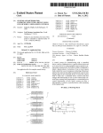
(57)
ABSTRACT
(63)
Continuation of application No. 12/705,096, ?led on
Feb. 12, 2010, noW Pat. No. 8,326,136.
(60)
Provisional application No. 61/151,881, ?led on Feb.
A control system for communicating With a controlled
device, such as a lighting device, a special effects device and
an in-scene device, in a photographic image-acquisition set
12, 2009.
ting using a camera body. The control system is con?gured to
Int. Cl.
body controls by a user. In response to detecting of the preset
pattern, the control system either communicates a poWer state
detect a preset pattern of actuation of one or more camera
(51)
G03B 15/06
G03B 17/00
G03B 15/03
(52)
(2006.01)
(2006.01)
(2006.01)
change signal to the controlled device or causes the camera
body to enter into a controlled device control mode that
changes the functionality of one or more camera body con
trols from a camera body functionality to a controlled device
US. Cl.
USPC ............... .. 396/56; 362/233; 396/4; 396/164;
control functionality, or both. Such a system can alloW a
396/297
(58)
Field of Classi?cation Search
photographer to control a controlled device While remaining
USPC ........... .. 396/1*5,56*58, 166, 175, 201, 280,
at the camera body.
396/299, 301*303; 348/333.13; 362/233
See application ?le for complete search history.
a
‘
I
t
r ................. --,
’ lggmm‘x YES:
m
\
25 Claims, 13 Drawing Sheets
’
summary’
v
t‘
1
ADJUST SIGNAL
'
1
1 .............. ...
'
1
'v
,
\v/
NO I‘
GENERATEAND :
\ “,1 TRANSMITPUWBR 1....’
Am“
\
............... ..
“W945
|
g
‘- ------------------ ~'
No
DE
No
ACTUATION
PA
I .................. a ..
1 ?-IANGE CAMERA BODY
~—-~', BACK :0 NON‘REMOTB
" DEVICE-Comm. MDDE
GWBRATEA DTRAN'S l ‘
SECOND POWER STATE
CHANGE SIGNAL
L...
935
US 8,538,250 B2
Page2
References Cited
U'S' PATENT DOCUMENTS
A
9/1965 Bnrgarella etal.
A
7/1966 Kagan
E
7/1969 Bnrgarella etal.
A
5/1972 Bnrgarella
3,205,803
3,259,042
RE26,627
3,659,509
3,728,947 A
3,782,258 A
3,810,214 A
4,047,191
4,194,818
4,201,434
4,209,244
4,333,719
4,344,680
4,351,594
4,355,309
4,482,895
4,509,845
4,571,049
4,573,786
4,603,954
4,636,052
4,643,551
4,693,582
4,740,804
A
A
A
A
A
A
A
A
A
A
A
A
A
A
A
A
A
4,816,850 A
4/1973 Harnden et a1.
1/1974 BOGkkOOi et 61.
5/1974 Malone etal.
9/1977
3/1980
5/1980
6/1980
6/1982
8/1982
9/1982
10/1982
11/1984
4/1985
2/1986
3/1986
8/1986
1/1987
2/1987
9/1987
4/1988
Coppaetal.
Matteson etal.
Tureck
Sahara et 61.
Takamietal.
Ishida etal.
Ishidaetal.
Hugheyetal.
Weinberg
Mizokami
Tsunefujietal.
Taniguchiet a1.
EgaWa etal.
Bowsher
Ohmori
Kawamura et a1.
ShandS
3/1989 Phillipeaux etal.
4,816,855 A
4,884,094 A
3/1989 Kitauraetal.
11/1989 Kitaura eta1~
4,988,584 A
5,016,037 A
1/1991
5/1991
10/1992
2/1994
5,159,375
5,283,610
5,299,012
5,359,375
A
A
A
A
5,384,611
5,422,543
5,436,531
5,521,708
5,640,623
5,692,223
A
A
A
A
A
A
5,708,833 A
5,721,971
5,734,934
5,754,898
5,848,306
A
A
A
A
Shaper
Taniguchi er a1
Taniguchi er a1
Sasaki
3/1994 Tsuruta etal.
10/1994
l/1995
6/1995
7/1995
5/1996
6/1997
11/1997
Clark
Tsuji eta1~
Weinberg
Weinberg
Beretta
Sasaki
lchikawaet a1.
1/1998 Kinney etal.
2/1998
3/1998
5/1998
12/1998
Sasaki
Horinishi er a1.
Nakano
Shono
7,437,063 B2
7,446,800 B2
10/2008 Clark
11/2008 Holmes
7,463,304
7,684,692
7,702,228
7,714,908
7,764,875
7,775,575
12/2008
3/2010
4/2010
5/2010
7/2010
8/2010
B2
B2
B2
B2
B2
B2
7,783,188 B2
7,834,894 B2
7,877,005 B2
7,880,761 B2
7,885,533 B2
7,965,335 B2
7,969,504
7,970,267
8,116,620
8,116,621
8,121,468
8,130,276
8,134,576
8,180,210
8,326,136
8,326,140
8,326,141
8,331,776
8,351,774
2001/0042149
2002/0009296
2002/0013161
2002/0067425
B2
B1
B2
B2
B2
B2
B2
B2
B1
B2
B1
B2
B2
A1
A1
A1
A1
2002/0067923 A1
2003/0128272 A1
Murray
Kashiyama
Clark
Holmes
Clark
Clark
8/2010 Clark
11/2010 Swanson et a1.
1/2011 Okubo
2/2011 Clark
2/2011 Clark
6/2011 Niblock
6/2011
6/2011
2/2012
2/2012
2/2012
3/2012
3/2012
5/2012
12/2012
12/2012
12/2012
12/2012
1/2013
11/2001
1/2002
1/2002
6/2002
Matsuda et a1.
Clark
King
King
Clark
Holmes
Swanson etal.
Clark
Clark
Clark
Clark
Clark
Clark
Ito etal.
Shaperetal.
Schaefferetal.
Iverson
6/2002 Fujimura
7/2003 Clough etal.
2003/0133018
2003/0193588
2004/0036774
2005/0006484
A1
A1
A1
A1
7/2003
10/2003
2/2004
1/2005
Ziemkowski
Yuen etal.
Nichols et al.
Ito
2005/0174434
2006/0014563
2006/0216009
2006/0275024
2006/0291016
2008/0180531
A1
A1
A1
A1
A1
A1
8/2005
1/2006
9/2006
12/2006
12/2006
7/2008
Chang etal.
Cheng
Kawarnura
MoNary
Ishigamietal.
Sekiguchi
2009/0102679 A1
2009/0129765
2009/0135262
2009/0278479
2009/0310012
A1
A1
A1
A1
4/2009 Schoettle ................. .. 340/8154
5/2009
5/2009
11/2009
12/2009
King
Ogasawara
Platneretal.
Ueda etal.
6,006,039 A
12/1999 Steinberg et a1.
2010/0122215 A1
5/2010 MacGregor ................. .. 715/834
6,029,013
6,052,539
6,088,542
6,127,940
6,167,199
6,278,481
6,351,610
6,353,711
6,366,737
6,400,907
6,404,987
6,430,369
6,453,154
6,524,237
6,618,557
6,625,399
6,683,654
6,718,135
6,731,952
6,748,165
6,778,764
6,798,986
2/2000
4/2000
7/2000
10/2000
12/2000
8/2001
2/2002
3/2002
4/2002
6/2002
6/2002
8/2002
9/2002
2/2003
9/2003
9/2003
1/2004
4/2004
5/2004
6/2004
8/2004
9/2004
2010/0158494
2010/0177212
2010/0202767
2010/0209089
2011/0001665
2011/0119409
2011/0128390
2011/0129207
2011/0167008
2012/0099847
2012/0120281
2012/0127340
2012/0127361
2012/0140088
2012/0181948
2012/0194699
2012/0207459
2012/0207460
2012/0243859
2013/0089313
2013/0094845
2013/0100340
6/2010
7/2010
8/2010
8/2010
1/2011
5/2011
6/2011
6/2011
7/2011
4/2012
5/2012
5/2012
5/2012
6/2012
7/2012
8/2012
8/2012
8/2012
9/2012
4/2013
4/2013
4/2013
A
A
A
A
A
B1
B1
B1
B1
B1
B1
B2
B1
B1
B1
B1
B1
B2
B2
B2
B2
B2
6,863,417 B2*
6,941,067
7,016,603
7,035,534
7,133,607
B2
B2
B2
B2
7,136,709 B2*
7,184,658 B2
7,362,965 B2
3/2005
9/2005
3/2006
4/2006
11/2006
Larkin etal.
Latorre
Yanaietal.
Weinberg
Fnkni
Schmidt
Numako er a1.
Numako er a1.
Numako er a1,
IZukaWa
Fnkni
Lee etal.
Haber et al.
MoGowan
Ziemkowski
Davis
Haijima
Kawasaki eta1~
Schaefferetal
Ogasawara
BarghinietalHagiuda
A1
A1
A1
A1
A1
A1
A1
A1
A1
A1
A1
A1
A1
A1
A1
A1
A1
A1
A1
A1
A1
A1
King
Holmes
sliirakawa
King
King
King
Clark
King etal.
King
Clark
Swanson etal.
Holmes
Clark
Clark
Clark
Kouno
Clark
Clark
Clark
Clark
Clark
Clark
Hill ............................. .. 362/233
Muramatsu
Clark
Shih eta1~
Clark
11/2006 Arling etal. .................. .. 700/65
2/2007 Squillace
4/2008 Clark
CN
CN
Ep
FOREIGN PATENT DOCUMENTS
2010-10600736.4
2/2012
2010-10600736.4
12/2012
0984320 A1
3/2000
EP
07760263.9
1/2011
EP
EP
07760263.9
8756458.9
7/2011
7/2011
US 8,538,250 B2
Page 3
EP
EP
EP
EP
EP
JP
JP
JP
JP
JP
JP
JP
JP
JP
JP
JP
JP
JP
JP
KR
WO
WO
WO
WO
WO
WO
WO
WO
WO
WO
WO
WO
WO
WO
WO
WO
11177995.5
11177995.5
10741797
11177995.5
11177997.1
56-143422
59-064821
59-170822
63-018874
05-093948
2002-244193
2002-318413
2003-172970
2003-215672
2003-325451
2004-072230
2006-149935
2007-067870
2010-510491
10-0728117
9638925
PCT/US2003/037271
2004049057
2007012041
2007118201
PCT/US2007/066162
PCT/US2006/028229
PCT/US2008/065137
PCT/US2008/065139
2008150902
2008150904
PCT/US2010/024088
2010093914
2010093927
2010093994
PCT/US2010/024108
A
A
A
A
A
A1
A1
A2
A2
A1
A1
A1
A1
A1
WO PCT/US2010/024195
WO PCT/US2011/044008
WO
2012009537 A1
WO PCT/US2012/025915
WO
2012161772 A1
12/2011
7/2012
8/2012
8/2012
12/2012
11/1981
4/1984
9/1984
1/1988
4/1993
8/2002
10/2002
6/2003
7/2003
11/2003
3/2004
6/2006
3/2007
8/2012
6/2007
12/1996
5/2004
6/2004
1/2007
10/2007
11/2007
2/2008
9/2008
9/2008
12/2008
12/2008
7/2010
8/2010
8/2010
8/2010
9/2010
9/2010
11/2011
1/2012
6/2012
11/2012
OTHER PUBLICATIONS
ASH Transceiver Impedance Matching; Document Created on Dec.
10, 2001; pp. 1 to 10; http://www.rfm.com/products/apnotes/anten
namatch.pdf; last viewed on Dec. 15, 2005.
Canon EOS 40D Usuer’s Manual; about Sep. 2007; Canon Corpo
ration.
Declaration ofJames E. Clark ?led on Feb. 18, 2005 in US. Appl. No.
10/306,759.
Ken Rockwell; How to Use Nikon Strobes Wirelessly, for Free!; Dec.
17, 2005; http://web.archive.org/web/20051217091704/http://www.
kenrockwell.com/nikon/ittlslave.htrn; last viewed at Internet archive
on Apr. 1,2010.
Nikon D2X; Sep. 2004; pp. 1 to 12; Nikon Corporation.
Nikon WT-l Transmitter User’s Manual; around Dec. 2003; Nikon
Corporation.
Nikon WT-2 Article, Part 1; Nikon Corporation; http://nikonimaging.
com/global/technology/scene/1 1/indeX.htm; last viewed on Mar. 14,
2008.
Nikon WT-2 Article, Part 2: Nikon Corporation; http://nikonimaging.
com/global/technology/scene/11/indeXi02.htm; last viewed on
Mar. 14, 2008.
Phil Askey, Nikon D2H Review: 15. Wireless: Digital Photography
Review, Wireless (Review of WT-l Transmitter); Dec. 2003; http://
www.dpreview.com/reviews/NikonD2H/page15.asp; last viewed on
Mar. 18, 2008.
Phil Askey, Nikon D2H Review: 1. Introduction: Digital Photogra
phy Review, Nikon D2H Review, Dec. 2003; http://www.dpreview.
com/reviews/NikonD2H/; last viewed on Mar. 18, 2008.
Phil Askey, Nikon D2Hs Preview: 1. Introduction: Digital Photogra
phy Review (includes Review of WT-2 Transmitter); Feb. 2005;
http://www.dpreview.com/articles/nikond2hs/; last viewed Mar. 14,
2008.
PocketWiZard MultiMAX Transceiver New Trigger Control Soft
ware Features, by LPA Design, Feb. 10, 2001; pp. 1 to 6, United
States.
PocketWiZard MultiMAX Transceiver Owner’s Manual, by LPA
Design, May 2001, pp. 1-55 and “Relay Mode” on p. 40, United
States.
Quantum FreeWire Transceiver; Jul. 17, 2005; pp. 1 to 7; http://web.
archive.org/web/20050717015832/http://www.qtm.com/wireless/
freewirehtml; last viewed at Internet Archive on Apr. 25, 2008.
U.S. Appl. No. 12/705,052, Jun. 27, 2012, Response to Of?ceAction,
Quantum FreeWire Transceiver; Nov. 15, 2004; pp. 1 to 7; http://web.
8,326,141.
US. Appl. No. 12/705,052, Sep. 5, 2012, Notice of Allowance,
8,326,141.
US. Appl. No. 12/705,096, Mar. 12, 2012, Of?ceAction, 8,326,136.
U.S.Appl. No. 12/705,096, Jun. 12, 2012, Response to Of?ceAction,
8,326,136.
US. Appl. No. 12/705,096, Aug. 8, 2012, Notice of Allowance,
8,326,136.
archive.org/web/20041115093657/http://www.qtm.com/wireless/
US. Appl. No. 12/705,164, Mar. 29, 2012, Of?ce Action.
U.S. Appl. No. 12/705,164, Jun. 29, 2012, Response to Of?ceAction.
U.S. Appl. No. 12/705,164, Sep. 7, 2012, Of?ce Action.
U.S. Appl. No. 12/705,164, Nov. 29, 2012, RCE.
U.S. Appl. No. 13/692,515, ?led Dec. 3, 2012.
US. Appl. No. 12/705,052, ?led Feb. 12,2010, 8,326,141.
US. Appl. No. 13/692,550, ?led Dec. 3,2012.
U.S. Appl. No. 12/705,096, ?led Feb. 12,2010, 8,326,136.
US. Appl. No. 12/705,164, ?led Feb. 12,2010.
Nikon D80 User’s Manual; see “Modeling Flash,” p. 98; published on
Aug. 11, 2006.
US. Appl. No. 13/735,325, Mar. 15, 2013, Of?ce Action.
U.S. Appl. No. 13/735,325, Mar. 21, 2013, Response to Of?ce Action
w/Terminal.
U.S. Appl. No. 13/708,326, Mar. 26, 2013, Notice ofAllowance.
U.S. Appl. No. 13/208,706, Mar. 26, 2013, Response to Of?ce
freewirehtml; last viewed at Internet Archive on Apr. 25, 2008.
Quantum FreeWire Transceiver; Oct. 7, 2001; pp. 1 to 6; http://web.
archive.org/web/20011007140624/http://www.qtm.com/wireless/
freewirehtml; last viewed at Internet Archive on Apr. 25, 2008.
Rob Galbraith; Casting Light on the PocketWiZard MiniTT1 and
FleXTT5; Parts 1 to 5; Feb. 16, 2009; http://www.robgalbraith.com/
bins/multiipage.asp?cid:7-9884-9903; last viewed on Jul. 12,
2012.
Robert Hanashiro; Equipment CorneriNews & Notes for all Those
Gear-Heads; Nov. 26, 2001; pp. 1 to 3; http://www.sportsshooter.
com/newsistory.html?id:594; last viewed on Sep. 17, 2002.
Strobist Blog: PocketWiZard FleXTT5 and MiniTT1: Full Review;
Feb. 16 to 18, 2009; blog comments, pp. 1 to 40; http://strobist.
blogspot.com/2009/02/pocketwiZard-?eXtt5 -and-minitt1-full.html;
last viewed on Feb. 18, 2009.
Strobist Blog: PocketWiZard FleXTT5 and MiniTT1: Full Review;
Feb. 16, 2009; pp. 1 to 11; http://strobist.blogspot.com/2009/02/
pocketwiZard-?eXtt5-and-minitt1-full.html; last viewed on Feb. 18,
2009.
XE-200 RF Shutter Release for Rebel 2000; http://
Zenopuseelectronix.com/XE-200.htrnl; last viewed on Sep. 9, 2002.
US. Appl. No. 11/305,668, Mar. 8, 2006, Of?ce Action, 7,133,607.
US. Appl. No. 11/305,668, Jun. 8, 2006, Response to Of?ce Action,
7,133,607.
U.S. Appl. No. 13/016,345, Apr. 26, 2013, Restriction Requirement.
U.S. Appl. No. 13/183,046,Apr. 29, 2013, Response to Of?ceAction.
US. Appl. No. 11/305,668, Jun. 13, 2006, Supplemental Response to
Request for Clari?cation by the Examiner, 7,133,607.
US. Appl. No. 11/305,668, Jun. 30, 2006, Notice of Allowance,
Affadavit of James E. Clark: FlashWiZard II SynchroniZer, signed
Mar. 20, 2008; previously submitted in US. Appl. No. 11/697,241.
US. Appl. No. 11/305,668, Mar. 29, 2007, Request for Correction of
Action.
Analog Devices Technical Data Sheet for ADF7020-1 Transceiver
IC, Analog Devices, Inc., 2005, pp. 1-44.
7,133,607.
Letters, 7,133,607.
US. Appl. No. 11/529,203, Aug. 14, 2007, Of?ce Action, 7,362,965.
US 8,538,250 B2
Page 4
US. Appl. No. 11/529,203, Oct. 16, 2007, Terminal Disclaimer,
7,362,965.
US. Appl. No. 11/529,203, Oct. 16, 2007, Response to Of?ceAction,
7,362,965.
US. Appl. No. 12/250,914, Jun. 29, 2009, Response to Of?ce Action
and Terminal Disclaimer, 7,702,228.
US. Appl. No. 12/250,914, Oct. 28, 2009, Terminal Disclaimer,
7,702,228.
US. Appl. No. 11/529,203, Oct. 25, 2007, Terminal Disclaimer,
US. Appl. No. 12/250,914, Dec. 3, 2009, Notice of Allowance,
7,362,965.
7,702,228.
US. Appl. No. 12/762,81 1, Dec. 28, 2010, Of?ce Action, 7,970,267.
US. Appl. No. 12/762,811, Mar. 28, 2011, Response to Of?ce
US. Appl. No. 11/529,203, Dec. 14, 2007, Notice of Allowance,
7,362,965.
US. Appl. No. 12/104,950, Dec. 31, 2009, Of?ce Action, 7,764,875.
US. Appl. No. 12/104,950, Feb. 1, 2010, Response to Of?ce Action,
7,764,875.
US. Appl. No. 12/104,950, Mar. 23, 2010, Notice of Allowance,
7,764,875.
US. Appl. No. 12/843,254, Jul. 27, 2010, Preliminary Remarks,
8,121,468.
US. Appl. No. 12/843,254, Aug. 25, 201 1, Of?ce Action, 8,121,468.
US. Appl. No. 12/843,254, Aug. 25, 2011, Response to Of?ce
Action, 8,121,468.
US. Appl. No. 12/843,254, Aug. 25, 2011, Terminal Disclaimer,
8,121,468.
US. Appl. No. 12/843,254, Nov. 28, 2011, Notice of Allowance,
8,121,468.
US. Appl. No. 13/399,333, Jun. 14, 2012, Of?ce Action, 8,351,774.
U.S.Appl.No. 13/399,333, Sep. 14, 2012, Response to Of?ceAction,
8,351,774.
US. Appl. No. 13/399,333, Sep. 14, 2012, Terminal Disclaimers,
8,351,774.
US. Appl. No. 13/399,333, Sep. 28, 2012, Notice of Allowance,
8,351,774.
US. Appl. No. 10/306,759, Aug. 29, 2003, Of?ce Action, 7,016,603.
US. Appl. No. 10/306,759, Dec. 18, 2003, Response to Of?ce
Action, 7,016,603.
US. Appl. No. 10/306,759, Dec. 24, 2003, Examiner Interview Sum
mary, 7,016,603.
US. Appl. No. 10/306,759, Mar. 27, 2004, Final Of?ce Action,
7,016,603.
US. Appl. No. 10/306,759, Apr. 15, 2004, Examiner Interview Sum
mary, 7,016,603.
US. Appl. No. 10/306,759, Apr. 20, 2004, Response to Final Of?ce
Action, 7,016,603.
US. Appl. No. 10/306,759, Aug. 24, 2004, Of?ce Action, 7,016,603.
US. Appl. No. 10/306,759, Feb. 18, 2005, Request for Continued
Examination, 7,016,603.
US. Appl. No. 10/306,759, Mar. 29, 2005, Of?ce Action, 7,016,603.
U.S.Appl. No. 10/306,759,Apr. 14, 2005, Response to Of?ceAction,
7,016,603.
US. Appl. No. 10/306,759, Jun. 29, 2005, Final Of?ce Action,
7,016,603.
US. Appl. No. 10/306,759, Aug. 25, 2005, Response to Final Of?ce
Action, 7,016,603.
US. Appl. No. 10/306,759, Sep. 16, 2005, Notice of Allowance,
7,016,603.
US. Appl. No. 10/306,759, Oct. 18, 2005, 312 Amendment,
7,016,603.
US. Appl. No. 10/306,759, Dec. 20, 2005, Response to 312 Amend
ment, 7,016,603.
US. Appl. No. 10/306,759, Jan. 4, 2006, Response to 312 Amend
ment, 7,016,603.
US. Appl. No. 10/306,759, Nov. 18, 2006, Certi?cate ofCorrection,
7,016,603.
US. Appl. No. 11/488/491, Oct. 16, 2007, Of?ce Action.
U.S. Appl. No. 11/490,322, Apr. 20, 2010, Of?ce Action, 7,880,761.
U.S.Appl. No. 11/490,322, Jul. 12, 2010, Response to Of?ceAction,
7,880,761.
US. Appl. No. 11/490,322, Sep. 15, 2010, Notice of Allowance,
7,880,761.
US. Appl. No. 12/250,914, Jun. 12, 2009, Of?ce Action, 7,702,228.
Action, 7,970,267.
US. Appl. No. 12/762,811, Mar. 28, 2011, Terminal Disclaimer,
7,970,267.
US. Appl. No. 12/762,811, Apr. 20, 2011, Notice of Allowance,
7,970,267.
U.S.Appl. No. 13/169,413, Dec. 20, 2011, Of?ceAction, 8,180,210.
US. Appl. No. 13/169,413, Jan. 16, 2012, Response to Of?ceAction,
8,180,210.
US. Appl. No. 13/169,413, Jan. 16, 2012, Terminal Disclaimers,
8,180,210.
US. Appl. No. 13/169,413, Mar. 22, 2012, Notice of Allowance,
8,180,210.
US. Appl. No. 13/438,500, Jun. 18, 2012, Of?ce Action.
U.S.Appl.No.13/438,500,Sep. 14, 2012, Response to Of?ceAction.
U.S. Appl. No. 13/438,500, Sep. 14, 2012, Terminal Disclaimers.
U.S. Appl. No. 11/697,241, Nov. 8, 2007, Of?ce Action, 7,437,063.
US. Appl. No. 11/697,241, Mar. 10, 2008, Response to Of?ce
Action, 7,437,063.
US. Appl. No. 11/697,241, Mar. 24, 2008, Examiner Interview Sum
mary, 7,437,063.
US. Appl. No. 11/697,241, Jun. 9, 2008, Notice of Allowance,
7,437,063.
US. Appl. No. 12/129,447, Apr. 12, 2010, Notice of Allowance,
7,775,575.
US. Appl. No. 12/129,447, Apr. 12, 2010, Examiner Amendment,
7,775,575.
US. Appl. No. 12/861,445, Sep. 30, 2010, Notice of Allowance,
7,885,533.
US. Appl. No. 13/021,951, Nov. 25, 2011, Notice of Allowance,
8,331,776.
US. Appl. No. 13/021,951, Feb. 13, 2012, Withdrawal of Notice of
Allowance, 8,331,776.
US. Appl. No. 13/021,951, Feb. 22, 2012, Of?ce Action, 8,331,776.
U.S.Appl.No. 13/253,596,Nov. 30,2011, Of?ceAction, 8,326,140.
U.S.Appl. No. 13/253,596, Feb. 29, 2012, Response to Of?ceAction,
8,326,140.
US. Appl. No. 13/253,596, May 9, 2012, Final Of?ce Action,
8,326,140.
US. Appl. No. 12/129,402, Apr. 19, 2010, Notice of Allowance,
7,783,188.
US. Appl. No. 13/208,686, Feb. 6, 2013, Of?ce Action.
U.S. Appl. No. 13/208,706, Dec. 26, 2012, Of?ce Action.
U.S. Appl. No. 13/183,046, Feb. 13, 2013, Of?ce Action.
U.S. Appl.
US. Appl.
US. Appl.
US. Appl.
No.
No.
No.
No.
13/735,325,
13/016,345,
13/438,500,
13/708,326,
?led Jan. 7, 2013.
?led Jan. 28, 2011.
?led Apr. 3, 2012.
?led Dec. 7, 2012.
U.S.Appl. No. 13/201,182, ?ledAug. 11,2011.
U.S.Appl.No. 13/201,185,?ledAug. 11,2011.
U.S. Appl. No. 13/208,686, ?ledAug. 12,2011.
U.S. Appl. No. 13/208,706, ?ledAug. 12,2011.
U.S. Appl. No. 13/201,281, ?ledAug. 12,2011.
U.S. Appl. No. 13/401,175, ?led Feb. 21, 2012.
US. Appl. No. 13/183,046, ?led Jul. 14,2011.
* cited by examiner
US. Patent
Sep. 17, 2013
Sheet 1 0f 13
US 8,538,250 B2
DETECT A PAEABTPATTEAN 0F
ACTUATION BY A USER OF QNA UR
mg
/~““““ MORE cAA/AEAA BQDY CONTROLS
ms -
“M;- GENEAA'E‘A A PQWEA STATE CHANGE
W/
, SIGNAL EN
126
OF THE PRESET PATTERN
\F‘
QQMMWIQAT THE PUWER
/
STATE CHANGE SIGNAL TO‘ ma AT ‘
1 15 m '
LEAST QNE DEVICE s0 THA'I‘ THE
AT LEAST 0N5 DEVEQE OPERATES
AT A FIRST EOWER STATE
' DETESTA I’RE?ET PATTERN 0F
ACTUATIGN BY A USER 0? (ENE OR
/ ‘ MORE CAMERA BQDY CONTROLS A
12% ---*
l
W GENERATE A POWER STA'I‘B QHANGE
SIGNAL EN
1'25 1*“
,
smNsE TO DBTECTIUN
OF THE PRESET PATTERN
"4|?
GGMAWNXCATE THE POWER
f'mf sTATE CHANGE SEGNAL T0 THE AT
1%,“!
'1
SPONSE TO DETECTIDN
LEAST ONE DEVICE SO THAT THE .
AT LEAST QNE DEVECE GPETES
AT A SECGND POWER STATE
‘
US. Patent
Sep. 17, 2013
Sheet 2 0f 13
US 8,538,250 B2
DETECT A PRESET PAT'E‘ERN a?
ACTUATION BY A USER 9F ONE 0R
/~"“"“"" MORE CAME
5am’ cow'mms
150
155 ~ ”
FM‘ CHANGE THE FUNC’I‘IONALITY {3F ONE OR MGRE
/
QAMERA BODY CQNTRGLS FROM CAMERA BODY
169
C'E‘IQNALETY TO GDNTROLLED DEVICE
CGWRQL FU N‘ C'YWNALYF‘?
M’
M... DETECT USER ACTUATIQN C31? ONE
Mr
J"
‘OR MORE CAMERA BUSY CONTROLS
1&5
HAVING CHANGES FUNC'HGNALITY
is
GENERATE GNE OR MORE POWER
,1”
ADEUST SEGNALS IN RESPONSE‘TQ
m ‘M’
SUCH USER ACTUA'I‘IQN
“M C(JMMUNICATE THE mwma ADJUST
W5
’/
SIGNAL(S} TQ A CGNTROLLED
DEVEQE
.
W».
/
18‘) W“
wt
7
nETEc? A mama": PATTERN ()F
ACTUATIGN BY A USER OF ONE GR
MURE CAMERA 30m! CONTROLS
?r’
,
CHANGE THE FUNCTiQNALI'E‘Y a? ONE OR MQRE
CAMERA BODY CUNTRGLS FROM CONTROLLED
:35 M’
DEVICE FUNC‘K‘IUNALITY BAQK, T0 {ZAMERA
BQDY EPUTPjéGTZQNALITY
,
a!’
US. Patent
Sep. 17, 2013
Sheet 3 0f 13
US 8,538,250 B2
US. Patent
Sep. 17, 2013
Sheet 4 0f 13
US 8,538,250 B2
US. Patent
Sep. 17, 2013
Sheet 5 0f 13
[4%
US 8,538,250 B2
US. Patent
Sep. 17, 2013
Sheet 6 0f 13
555 -
US 8,538,250 B2
‘@113?
1*
5m:
2
YES
/
GENERATE AND TRANSMIT ICE;
SIGNAL WI'I‘E"I FiRST SET
ILLUMINATION VALUE
mv
v
vim
v
..
WLFMaN' " SET Emmi’!
v53$
CAUSE MQQIZMNG- mam *m
CHANGE To gamma SET
iLLUMINATION VALUE
Bi}; MODE
ENABLED
IL
' .
DETECTED
§3§ W
4r
7
,
GEN?RATE A D TIM SM???
POWER CHANGE SIGNAL (WETH
FIRST 3E1’ POWER VfRLUE'}
Q?Nmm-m AND TRANSMIT PQWBR
CHANGE SIGNAL {WITH gamma
s51: POWER VALUE)
FIG.
US. Patent
Sep. 17, 2013
Sheet 7 0f 13
US 8,538,250 B2
' 10c 31mm,
@“"
‘1’
‘
g
v 555
[IMPLEMEN SETDELAY}
m _»\
“3),
K
,
GENERATE AND *I‘RANSMET
iOC EIGNAL WITH F1118?
v
CAUSE REMQTE DEVICE "r0
CHANGE TO SECOND SET
POWER VALUE
-
SET 9' Wm
-
G
V
ALUE
US. Patent
Sep. 17, 2013
Sheet 8 0f 13
US 8,538,250 B2
VOLTAGE 6w“
5 S DELAY
ssnaw
‘1.58;
v/n
__ __ 5 SFADELAY
Iitlskr!.a
l
US. Patent
Sep. 17, 2013
Sheet 9 0f 13
US 8,538,250 B2
an:
ms
4i’
we»
W3C
\
9M3
/
3%
grim
ma
$28
zawzsa,/
é,
>?mii
+
sa
835
.
*
2M:
fags
9.5:: REF;
832
*~
TEME
r”
2334
\
ass
US. Patent
Sep. 17, 2013
Sheet 11 0f 13
US 8,538,250 B2
"W' Ah. Dmviw
Alt. Device
Exient 5964M}
Extent 1 8646 3
E
AR Dswce
Receiving
19111121813)".....,,...frffi§fi.?éém>
M
‘111125111
“*3 Maia! E?écts Devices 1316;"
.. "x m,
MM:
.Awm,r1.n\_mwm
-,
i
4
i
A]:1 a
g ,
“MW!
w“
i
I’?
i,
%
$8‘
7?
f Dwiw
Means 1644(1)
a
Rmeivmg
Means mam}
\
WC
I,2
fb,“
DH,.Bmy»,
WM
m
CM
,,
‘I
“nag; u
, Wireless Cumin.
Link 1641?:
k.
A
‘Gamers, Boriy
“WmymemwWDa1”wmK,IM”
“mMma.swmMKqu1.“m
Conimi(s) 1604 “NMNN
22%,.
1 “"“mm A11, Camera.
Bandy Emmi;
193i)
\\\‘
,,
{am$.“mm1,my.M.N1QM
,.\,.
M
84
Maw
.1.
Wm!
u,, \X
Vii‘:
.1.“X”,
w
M
\1‘
A\
“Magi
i
\
a
'
‘Mifmmsmsttmg Maams 1036
\_
vim,“ \NWMI? Wireiess (211111111,
“3,1,, ,
Dcvma
1920(1}
Bxmm
.
\
Link. 1048
Devzw
i024
lQi7¥§}.2,...m_.., ‘x
\
nu
Receiving
Means 1952(1)
. 3
,
mwmzviw 1111;, It»,
RmCS
av
Alt. Davwe
Extent 1063mm"
M
Alt. Device °"'
Extent NEW}
?1
US. Patent
Sep. 17, 2013
Sheet 12 0f 13
US 8,538,250 B2
US. Patent
Sep. 17, 2013
om w
5%
mow."
gm".
Sheet 13 0f 13
US 8,538,250 B2
US 8,538,250 B2
1
2
SYSTEMS AND METHODS FOR
COMMUNICATING WITH A DEVICE USING
ONE OR MORE CAMERA BODY CONTROLS
acquisition because the ambient lighting is necessary for the
photographer and any assistants to see While moving around
the studio and/or readying the scene for image acquisition.
Usually, a photographer or photographer’ s assistant manually
controls the pertinent ambient lighting device(s) using con
RELATED APPLICATION DATA
ventional dedicated controls.
This application is a continuation of US. application Ser.
SUMMARY OF THE DISCLOSURE
No. 12/705,096, ?led Feb. 12, 2010, and titled “Systems and
Methods For Communicating With a Device Using One or
In one implementation, the present disclosure includes a
method of communicating With a remote lighting device
using a camera body, including detecting a ?rst preset pattern
More Camera Body Controls,” Which application claims the
bene?t of priority of US. Provisional Patent Application No.
61/151,881, ?led on Feb. 12, 2009, and titled “Systems And
Methods For Communicating WithA Device Using One Or
More Camera Body Controls.” Each of these applications is
incorporated by reference herein in its entirety.
of actuation by a user of at least one ?rst camera body control
on the camera body; generating a ?rst poWer level signal in
response to said detecting of the ?rst preset pattern of actua
tion; Wirelessly communicating the ?rst poWer level signal to
the remote lighting device so as to cause the remote lighting
FIELD OF THE INVENTION
device to operate at a ?rst poWer level; after communicating
the ?rst poWer level signal, detecting a second preset pattern
The present invention generally relates to the ?eld of pho
tography. In particular, the present invention is directed to
systems and methods for communicating With a device using
20
signal in response to said detecting of the second preset pat
tern of actuation; and Wirelessly communicating the second
one or more camera body controls.
poWer level signal to the remote lighting device so as to cause
the remote lighting device to operate at a second poWer level.
BACKGROUND
25
preset pattern of actuation by a user of at least one ?rst camera
body control on the camera body; a means for generating a
neWspapers, billboards, posters and scrapbooks and are dis
30
graphic images are acquired using only natural ambient light,
poWer level; a means for after communicating the ?rst poWer
level signal, detecting a second preset pattern of actuation by
35 a user of at least one second camera body control on the
camera body; a means for generating a second poWer level
checking for unWanted shadoWs, glare, re?ection, etc. and/or
checking for desired shadoWs and other lighting effects. Gen
signal in response to said detecting of the second preset pat
tern of actuation; and a means for Wirelessly communicating
the second poWer level signal to the remote lighting device so
erally, these modeling lights are either kept poWered up to a
suf?cient level or turned up to a su?icient level When needed.
?rst poWer level signal in response to said detecting of the ?rst
preset pattern of actuation; a means for Wirelessly communi
cating the ?rst poWer level signal to the remote lighting device
so as to cause the remote lighting device to operate at a ?rst
many other images are acquired using photographic ?ash
lighting. When image-acquisition ?ash lighting is used, a
photographer often uses one or more modeling lights prior to
image acquisition for any of a variety of reasons, such as
In another implementation, the present disclosure includes
a system for communicating With a remote lighting device
using a camera body, including a means for detecting a ?rst
Photography is an integral component of modern society,
and photographs pervade our lives. Photographic images
appear, for example, in books, magaZines, catalogs, journals,
played in homes, art galleries, retail stores, shopping malls,
o?ice buildings and many other places. While many photo
of actuation by a user of at least one second camera body
control on the camera body; generating a second poWer level
40
as to cause the remote lighting device to operate at a second
Keeping the modeling lighting poWered up can be problem
poWer level.
atic due to the heat this type of lighting generates, Which can
be uncomfortable for live models and detrimental to heat
includes a machine-readable hardWare storage medium con
In still another implementation, the present disclosure
sensitive still subjects. Occasionally turning up the poWer of
modeling lighting can be inconvenient, even using more
taining machine-executable instructions for performing a
45
recent remotely-controlled modeling lights.
Many photographic images are acquired Without adding
camera body, said machine-executable instructions including
a set of instructions for detecting a ?rst preset pattern of
special effects to the captured scene. HoWever, many other
actuation by a user of at least one ?rst camera body control on
the camera body; a set of instructions for generating a ?rst
photographic images are acquired using added special
effects, such as arti?cial Wind, snoW, mist and rain, and/or
50
using contrived scenes that use in-scene props and other
items, such as in-scene lighting. Today, many special effects
generators, for example, fans, snoW shakers, mi sters and rain
poWer level signal in response to said detecting of the ?rst
preset pattern of actuation; a set of instructions for Wirelessly
communicating the ?rst poWer level signal to the remote
lighting device so as to cause the remote lighting device to
operate at a ?rst poWer level; a set of instructions for after
systems, are turned off and on electronically using dedicated
on/off and/or speed/poWer control sWitches. Similarly, in
method of communicating With a controlled device using a
55
scene lighting can often be controlled using such dedicated
communicating the ?rst poWer level signal, detecting a sec
control sWitches. Typically, a photographer, or more often a
ond preset pattern of actuation by a user of at least one second
camera body control on the camera body; a set of instructions
photographer’s assistant, has the task of controlling the
operation of any special effects devices and in-scene lighting
for generating a second poWer level signal in response to said
detecting of the second preset pattern of actuation; and a set of
for image acquisition.
60
In addition, some photographic settings, such as very loW
instructions for Wirelessly communicating the second poWer
level signal to the remote lighting device so as to cause the
remote lighting device to operate at a second poWer level.
light scenes photographed in a photography studio (or other
location having controllable ambient lighting), require ambi
ent lighting to be loWered or turned off during image acqui
sition so that the ambient light does not interfere With image
acquisition. Often, this ambient lighting needs to remain on
except for short periods at and around the time of image
BRIEF DESCRIPTION OF THE DRAWINGS
65
For the purpose of illustrating the invention, the draWings
shoW aspects of one or more embodiments of the invention.
US 8,538,250 B2
3
4
However, it should be understood that the present invention is
not limited to the precise arrangements and instrumentalities
shoWn in the drawings, Wherein:
lighting effects and levels that Will appear in images captured
using ?ash photography; alloWing a photographer to control
operation of remote special effects; alloWing a photographer
to control ambient and in-scene lighting; alloWing a photog
rapher to control remotely controllable devices appearing in a
photographic scene; and any combination thereof, all Without
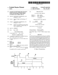
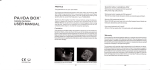
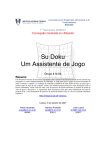
FIG. 1A is a ?oW diagram illustrating a method of com
municating With a device using one or more camera body
controls;
FIG. 1B is a ?oW diagram illustrating another method of
having to remove an eye from the camera’s vieW?nder or
communicating With a device using one or more camera body
live-vieW display.
Method 100 typically begins at step 105 by detecting
controls;
FIG. 2 is a diagram of a photographic system that includes
Whether or not a user has actuated one or more camera body
a camera, a Wireless controller, a remote multifunctional
controls of a camera body in a preset pattern setup to corre
spond to the user’s desire to control one or more controllable
devices located remote from the camera body. As used herein
lighting system incorporating a modeling lighting source, and
a special effects fan, Wherein the system is con?gured to
perform steps of the methods of FIG. 1A and/or FIG. 1B;
FIG. 3 is a high-level diagram of the Wireless controller of
FIG. 2;
FIG. 4 is a diagram illustrating a computer-based environ
and in the appended claims, the term “pattern” is intended to
cover multiple actuations of one or more camera body con
trols, such as three rapid partial presses of a shutter-release
button, as Well as the simultaneous and/or sequential actua
tion of tWo or more controls, such as actuating a backlighting
control button While holding doWn a menu on/off sWitch,
ment for con?guring a Wireless controller, such as the exter
nal Wireless controller of FIGS. 2 and 3;
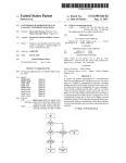
FIGS. SA-B together contain a ?oW diagram illustrating a
method of controlling the scene illumination output of mod
eling lighting using a controller having a Wake mode, an
autofocus assist mode and a backlight mode, such as the
controller of FIGS. 2 and 3;
FIG. 6 is an example timing diagram illustrating function
20
among many other possibilities. In addition, it is noted that as
used herein and in the appended claims the term “camera
body control” and like terms mean a control that causes a
signal to be generated either internally or externally relative
25
to the camera body and that is used to control functionality
inherent in the camera body itself, any lens attached thereto
and any image-acquisition ?ash-lighting device attached to
ing of the autofocus assist mode of a Wireless controller, such
as the controller of FIGS. 2 and 3, using the control settings
the camera body or responsive to a ?ash-sync signal gener
ated by the camera body. Because the present disclosure is
illustrated on the screen of the graphical user interface of FIG.
directed to controlling devices starting prior to any image
4;
FIG. 7 is an example timing diagram illustrating function
30
ing of the Wakeup mode of a controller, such as the controller
of FIGS. 2 and 3, using the control settings illustrated on the
screen of the graphical user interface of FIG. 4;
FIG. 8 is a diagram illustrating circuitry and corresponding
signaling suitable for use in the camera body interface of a
controller, such as the controller of FIGS. 2 and 3;
35
any type of sWitch or other actuator, mechanical, soft or
FIG. 9 is a ?oW diagram illustrating another method of
using a camera body to control illumination output of mod
otherWise. A camera body signal can also be generated by
eling lighting;
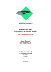
FIG. 10 is a high-level diagram illustrating a ?exible con
capturing, a shutter-release signal is excluded from being a
relevant camera body signal. As those skilled in the art Will
appreciate, the term “shutter” as used herein and in the
appended claims is intended to refer to a mechanical shutter,
an electronic shutter and any combination thereof and equiva
lent thereto.
A camera body signal can be generated by a user actuating
40
circuitry internal to a camera body in response to any one or
more of a variety of events, such as a user actuating a sWitch
trol system for controlling a host of devices, including mod
(e.g., a partial press (a/k/a “half press”) of a shutter release
eling lighting devices, special effects devices, non-modeling
button or a press of an autofocus button or a depth-of-?eld
continuous lighting devices and in-scene non-lighting
previeW button or the actuation of a camera-body mode dial)
and camera body circuitry determining a particular function
is needed (e.g., a camera processor determining that the lens
needs to be autofocused), among others. Examples of a cam
devices, using one or more camera body controls of a camera
body;
45
FIG. 11 is an elevational vieW of a photography studio
containing a photographic system that includes a camera,
ambient lighting devices and an in-scene lighting device,
Wherein the system is con?gured to alloW a photographer to
control operation of the ambient lighting devices and in-scene
lighting device using the body of the camera; and
FIG. 12 is a diagram illustrating a digital camera-body
status communication signal containing autofocus assist and
backlight information that a controller of the present disclo
era body signal generated internally within the camera body
50
include, but are not limited to, a camera body Wake signal, a
camera body sleep signal, an autofocus assist signal, a camera
body backlighting on/ off signal, a menu control signal, a ?ash
compensation signal, a signal from a “click Wheel” or other
user control, such as a partial-press sWitch signal generated
upon a partial press of a shutter-release button. Examples of a
camera body signal generated externally include, but are not
sure can use to control one or more modeling lighting device 55 limited to, a partial-press sWitch signal initiated from an
external device and communicated to the camera body, for
example, via an external communications port on the camera
body (e.g., a hotshoe, a proprietary connector port, a motor
drive port, a universal serial bus (USB) port, a “FIREWIRE”
(S)
DETAILED DESCRIPTION
Referring noW to the draWings, FIG. 1A illustrates a
method 100 of communicating With a remote device using
60
one or more camera body controls. As Will be readily under
stood by those skilled in the art after reading this entire
disclosure, a communication method containing broad con
cepts disclosed herein, such as method 100, is useful for a
number of purposes, including: alloWing a photographer to
use modeling lighting to check for unWanted and/or Wanted
(IEEE 1394) port, etc.) and any other camera body signal that
can be initiated or generated externally from the camera body.
65
Speci?c examples are described beloW in detail to give the
reader an understanding of hoW step 1 05 can be implemented.
HoWever, those skilled in the art Will appreciate that con
trols provided to a particular camera body and camera body
control signals vary to a great extent such that it is impractical
to cover all current conventional camera body controls and
US 8,538,250 B2
5
6
camera body control signals, and that it is virtually impossible
depending on the desire of the designer. Like step 105, the
preset pattern can be detected from camera body signals
generated internally or externally relative to the camera body.
At step 125 a poWer state change signal for controlling the one
to predict future camera body controls and camera body con
trol signals. That said, those skilled in the art Will readily be
able to implement the broad concepts of the present disclo
or more remote devices is generated in response to the detec
sure for virtually any one or more camera body controls
and/ or any one or more camera body signals. The detection of
the one or more camera body signals can be performed inter
tion of the preset camera body control actuation pattern in
step 120. Like generating step 110, generating step 125 can be
performed internally or externally relative to the camera
nally or externally relative to the camera body, for example,
by a controller, such as a microprocessor/software systems,
hardWare controller, a combination of these, or other cir
cuitry. Several examples of internal and external detection are
described beloW in detail.
At step 110 a poWer state change signal for controlling one
body, depending on the con?guration of the overall system.
At step 130 the ?rst poWer state change signal is communi
cated to the at least one controlled device so as to cause
device(s) to change to a second poWer state corresponding to
the poWer state change signal generated at step 125. The
implementation of step 130 may be, for example, the same as
the implementation of step 115 described above. Details of
or more remote devices is generated in response to the detec
tion of the preset camera body control actuation pattern in
step 105. Like detecting step 105, generating step 110 can be
performed internally or externally relative to the camera
method 100 are described in more detail beloW, especially in
connection With FIG. 9.
FIG. 1B illustrates another method, method 150, of com
body, depending on the con?guration of the overall system.
For example, if a particular camera body includes an internal
controller, generating step 110 canbe performed internally. In
municating With a remote device using one or more camera
20
another example in Which a controller is provided externally
to a camera body, generation step 110 is performed outside
the camera body. As Will become apparent from the detailed
appear in images captured using ?ash photography; alloWing
examples provided beloW, the ?rst poWer state change signal
can be, for example, a signal recogniZable directly by the
target, i.e., controlled, device(s) or recogniZable by an inter
25
mediate device, such as a Wireless receiving device that, in
turn, generates one or more signals recogniZable by the con
trolled device(s). The relevant signaling depends on the over
all con?guration of the system. As Will also be discussed
beloW, the ?rst poWer state change signal may be accompa
nied by and/or contain data, such as one or more poWer level
values and/or a poWer state change time delay value for a
30
combination thereof, all Without having to remove an eye
from the camera’s vieW?nder or live-vieW display.
Method 150 typically begins at step 155 by detecting
controls of a camera body in a ?rst preset pattern setup to
correspond to the user’s desire to control one or more con
35
trollable devices located remote from the camera body.
Again, the term “pattem” is intended to cover multiple actua
tions of one or more camera body controls, such as three rapid
partial presses of a shutter-release button, as Well as the simul
taneous and/or sequential actuation of tWo or more controls,
nicated to the at least one controlled device so as to cause
device(s) to operate at a ?rst poWer state corresponding to the
poWer state change signal. As alluded to above relative to
generating step 110, the Way the controlled device(s) are
a photographer to control operation of remote special effects;
alloWing a photographer to control ambient and in-scene
lighting; alloWing a photographer to control remotely con
trollable devices appearing in a photographic scene; and any
Whether or not a user has actuated one or more camera body
subsequent poWer change, among others. Examples of such
data are described beloW in the detailed examples.
At step 115 the ?rst poWer state change signal is commu
body controls. As With method 100 of FIG. 1A, method 150 of
FIG. 1B is useful for a number of purposes, including: alloW
ing a photographer to use modeling lighting to check for
unWanted and/or Wanted lighting effects and levels that Will
40
caused to operate at the ?rst poWer state depends on the
con?guration of the overall control system. For example, if a
particular controlled device has user-settable poWer levels
settings that can be input Wirelessly, then the system can be
con?gured, for example, so that the poWer state change signal
contains a desired poWer level setting. In another example, if
a particular controlled device has user-settable poWer level
settings that can be input only either through an onboard user
45
interface on the device or through a Wired port on the device,
then the system may include tWo Wireless devices, a ?rst one
at the camera body and a second one connected to the Wired
50
such as actuating a backlighting control button While holding
doWn a menu on/ off sWitch, among many other possibilities.
In addition, it is noted that as used herein and in the appended
claims the term “camera body control” and like terms mean a
control that causes a signal to be generated either internally or
externally relative to the camera body and that is used to
control functionality inherent in the camera body itself, any
lens attached thereto and any image-acquisition ?ash-lighting
device attached to the camera body or responsive to a sync
signal generated by the camera body. Because the present
disclosure is directed to controlling devices starting prior to
any image capturing, a shutter sync signal and related signals
input port of the controlled device. In one scenario, the ?rst
for triggering/controlling strobe lighting devices for image
Wireless device at the camera body may transmit a simple
acquisition lighting are excluded from being a relevant cam
era body signal. As those skilled in the art Will appreciate, the
term “shutter” as used herein and in the appended claims is
remote-device trigger signal to the second Wireless device at
the controlled device. In this case, upon receiving the trigger
55
signal the second Wireless device Would, for example, send
the illumination output level setting. If multiple controlled
intended to refer to a mechanical shutter, an electronic shutter
and any equivalent thereto.
A camera body signal can be generated by a user actuating
any type of sWitch or other actuator, mechanical, soft or
devices are being controlled at the same time via Wireless
devices, each of these devices may have a unique identi?er
that a properly con?gured system can utiliZe to implement
60
differing control schemes among the multiple devices.
Detailed examples of Ways of implementing transmitting step
circuitry internal to a camera body in response to any one or
more of a variety of events, such as a user actuating a sWitch
(e.g., a partial press (a/k/a “half press”) of a shutter release
115 are presented beloW.
At step 120 it is determined Whether or not a user has
performed a preset pattern of camera body control actuation.
This preset pattern may be the same as the preset pattern
described above relative to step 105, or it may be different,
otherWise. A camera body signal can also be generated by
button or a press of an autofocus button or a depth-of-?eld
65
previeW button or the actuation of a camera-body mode dial)
and camera body circuitry determining a particular function
is needed (e.g., a camera processor determining that the lens