1
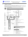
Operating instructions for
Papantonatos submersible pumps
Standard units
PAPANTONATOS SA
Roumelis & Adelfon Ntouna 1
13671 Acharnes Attiki - Greece
Tel (+30) 210 2431111 Fax (+30) 210 2431601
Internet : www.papantonatos.gr
E-mail : [email protected]
Operating instructions for
submersible pumps
TABLE OF CONTENTS
0.
0.1.
0.2.
0.3.
1.
1.1.
1.2.
1.3.
2.
2.1.
2.2.
General information .........................................................................................................................4
General description ....................................................................................................................................... 4
Additional documentation ............................................................................................................................. 4
Symbols......................................................................................................................................................... 4
Safety instructions ...........................................................................................................................5
Unauthorized alteration and construction of replacement parts .................................................................... 5
Prohibited modes of operation ...................................................................................................................... 5
Statement of nonliability ............................................................................................................................... 5
Technical data...................................................................................................................................6
Delivery contents .......................................................................................................................................... 6
General data .................................................................................................................................................. 6
2.2.1.
2.2.2.
2.2.3.
3.
4.
4.1.
4.2.
4.3.
4.4.
4.5.
4.6.
5.
5.1.
5.2.
Hydraulic connection .......................................................................................................................7
Installation.........................................................................................................................................8
Procedures upon receipt of delivery.............................................................................................................. 8
General remarks ............................................................................................................................................ 8
Work and checks before installation ............................................................................................................. 9
Installation of pre-assembled pump unit ....................................................................................................... 9
Assembly during installation....................................................................................................................... 10
Installation tips to ensure long-life for the pump-unit................................................................................. 11
Electrical connection .....................................................................................................................12
Connection of motor ................................................................................................................................... 12
Labeling of conductor ends and rotation direction of motor....................................................................... 12
5.2.1.
5.3.
5.4.
5.5.
5.6.
5.7.
5.8.
5.9.
5.10.
6.1.
6.2.
7.
7.1.
8.
8.1.
8.2.
8.3.
8.4.
8.5.
9.
9.1.
9.2.
9.3.
9.4.
9.5.
10.
11.
Single-phase motors ............................................................................................................................................. 12
Motors with one power supply cable .......................................................................................................... 12
Motors with two power supply cables, parallel connection ........................................................................ 12
Motors with two power supply cables (open delta connection) .................................................................. 12
Motor connection diagrams......................................................................................................................... 13
Protective measures against shock-hazard voltages .................................................................................... 14
Motor protection.......................................................................................................................................... 14
Short circuit protection................................................................................................................................ 15
Insulation test .......................................................................................................................................... 15
5.10.1.
5.10.2.
6.
Normal operating conditions.................................................................................................................................. 6
Fitting position ....................................................................................................................................................... 6
Starting frequency .................................................................................................................................................. 6
Motors with one main feed line ............................................................................................................................ 15
Motors with two or more main feed lines ............................................................................................................. 15
Starting ............................................................................................................................................16
General instructions .................................................................................................................................... 16
First switching - on...................................................................................................................................... 16
Operation.........................................................................................................................................18
Starting frequency ....................................................................................................................................... 18
Maintenance....................................................................................................................................19
General information .................................................................................................................................... 19
Pump unit .................................................................................................................................................... 19
Electrical system ......................................................................................................................................... 19
Removal ...................................................................................................................................................... 19
Overhaul of the pump.................................................................................................................................. 20
Storage ............................................................................................................................................21
General remarks .......................................................................................................................................... 21
Requirements for the storage area ............................................................................................................... 21
Storage up to four weeks............................................................................................................................. 21
Storage between 1 and 24 months............................................................................................................... 21
Storage for over 24 months ......................................................................................................................... 21
Transport.........................................................................................................................................22
Operating problems and their elimination...................................................................................23
PAPANTONATOS S.A. v.1.0 10.2004
Page 3 of 24
Operating instructions for
submersible pumps
0.
General information
0.1.
General description
Standard submersible pumps serve to transport cold clean water under normal operating conditions.
Other uses or operating purposes must be agreed upon with the manufacturer.
Submersible pumps are subjected to a thorough inspection before leaving the factory and equipped
with operating instructions for fitting, starting, care etc., which conform to international safety
regulations.
These instructions describe the procedures to be used for fitting, operation and maintenance of
standard submersible pumps.
This documentation is to be kept by the user so that it is available to the
operating personnel at any time.
0.2.
Additional documentation
This documentation describes the fitting, operation and maintenance of standard submersible pumps.
You will find further information
- in the instructions for filling standard submersible motors.
- in the data sheet
- in the order confirmation
Should the information in these operating instructions differ from that in the order confirmation or in the
data sheet, follow the information in the order confirmation or the data sheet.
0.3.
Symbols
The following symbols are used in this documentation in order to especially emphasize important
information and call attention to dangers :
General information: Not heeding this can lead to damage.
Live components: Contact with these components can be deadly.
Caution: Not heeding this can lead to severe damage or to injury/health
problems.
Warning: Not heeding this can lead to destruction of the unit or to severe
injury/health problems.
Information placed directly on the machine and/or the unit, as for example
- Rotation arrow
- Labeling of connections
- Rating plate
must absolutely be heeded.
PAPANTONATOS S.A. v.1.0 10.2004
Page 4 of 24
Operating instructions for
submersible pumps
1.
Safety instructions
The unit may only be operated by trained personnel, only in a completely assembled condition,
and with a completely filled and immersed pump unit.
This documentation is to be kept by the user so that it is available to
operating personnel at any time.
- Guards for movable parts (e.g. coupling) must not be removed from the machine while it is in
operation.
- Danger from electric energy must be eliminated (for details see e.g. the regulations of the VDE
and the local power supply companies).
Before maintenance and repair work, the motor of the pump unit must first
be completely separated from the power supply.
The user must be certain that all maintenance, inspection and assembly work is completed by
appropriately qualified technical personnel, sufficiently informed by thorough study of the
operating instructions.
Work on the machine must only ever be performed when it is stopped. The procedures for
stopping the machine in the operating instructions absolutely must be followed.
Pumps or units which convey health endangering substances must be decontaminated.
Immediately after finishing work, all safety and protective systems must be replaced and/or put
back into operation.
Before restarting, the points listed in the section “First switching-on” must be heeded.
All work on the electrical system may only be performed by qualified
electrician!
All work on the hydraulic connections may only be performed by
qualified fitters.
1.1.
Unauthorized alteration and construction of replacement parts
Alterations to the unit are only permitted after speaking with the manufacturer. Safe operation is only
guaranteed with original replacement parts and accessories authorized by the manufacturer. The use
of other parts releases liability.
1.2.
Prohibited modes of operation
The operation safety of the delivered unit is only guaranteed for use according to the regulations in
chapter 2 “Technical data” of the operating manual. The limits given in the data sheet may in no case
be exceeded.
1.3.
Statement of nonliability
By not heeding this documentation, product liability is rendered void.
PAPANTONATOS S.A. v.1.0 10.2004
Page 5 of 24
Operating instructions for
submersible pumps
2.
Technical data
Each unit has been individually manufactured according to the special requirements of the customer.
The specific technical data regarding head, delivery rate, current requirement, minimum permissible
flow velocity on the external motor surfaces etc. can be found in the data sheet delivered with the unit
or in the order confirmation.
2.1.
Delivery contents
• pump unit
• these operating instructions
• technical data sheet
• instructions for filling submersible motors
2.2.
General data
2.2.1. Normal operating conditions
−
−
−
−
−
−
−
−
−
−
−
Pump-unit (pump+motor) must always be completely submerged
Minimum cooling flow velocity along the motor surface as per motor data sheet
Ambient temperature as per data sheet
sand content
: approx. 25mg/lit
no impurities which could lead to deposits and blockages within the pump or to deposits on the
motor surface
no occurrence of water hammer
no operation against closed slide valve
operation within prescribed voltage tolerance
permissible operational range : 50 to 120% of the optimal delivery rate
correctly selected and adjusted motor protection
observation of the max. permissible starting frequency
At higher surrounding temperatures and/or lower flow velocities on the external
motor surfaces, or if there is risk of clogging, special measures for heat
dissipation are required. This must be checked with the manufacturer by indicating
the surrounding conditions. In this case, the suitability of the unit for its planned
application must be confirmed by the manufacturer.
For units installed according to the instructions given in this documentation, noise level
produced by the motor (working in his valid range), shouldn’t exceed 70 db (A).
2.2.2. Fitting position
The following criteria must be taken into account in determining the fitting position and depth:
− Vertical fitting in a well above the filter line, so that a perfect flow is guaranteed along the motor
− Sufficient water cover
− A static water level at least 2m above the pump exit
− A dynamic water level above the suction housing, taking into account the required NPSH value
(see pump characteristic) for the pump
− Flow rate (see pump characteristic)
− Supply conditions of the pumping medium (dependent upon the fitting conditions)
Regardless of the above mentioned criteria, the pump unit must definitely be
installed above the well filter. If this must be changed, direct suction within the
filter line must be prevented by suitable measures (e.g. blind tube in the filter,
outer pump mantle, pump with sand protection jacket.
Other use and operating conditions must be checked with the manufacturer.
2.2.3. Starting frequency
The amount of regularly distributed starts per hour must be taken from the data sheet. Higher starting
frequencies are only permissible upon agreement with the manufacturer.
Amount of maximum permissible starts in sequence:
Cold motor / Warm motor .............. : 3 starts / 2 starts
Rest interval after each cycle............ : 5 minutes
PAPANTONATOS S.A. v.1.0 10.2004
Page 6 of 24
Operating instructions for
submersible pumps
3.
Hydraulic connection
Exemplary construction of a water supply system is depicted in Fig. 3.1. Since this shows a basic
arrangement, the actual layout must be suited to local and technical conditions.
The additional listed components are recommendations which serve the purpose of operational safety
and the protection of the pump unit.
All work on the hydraulic connection may only be done by qualified
fitters.
Wt E t
U> 2m
1a
1b
2
3
4
5
6
7
8
9
10
11
12
13
14
15
16
17
18
Submersible motor
Submersible pump
Non-return valve
Ascending pipeline
Fastening clamps for power supply and signal cables
Support clamp
Elbow with manometer connection
Control valve
Delivery pipe
Pressure tank or high level tank
Terminal box / outlet for power supply cable
Switch cupboard with switching, control and signal units
Pressure or float switch
System fuses
Centering device
Manometer
Well shaft vents
Double orifice air valve
Safety valve
We also recommend for the safety of the pump unit or for automatic
operation
19a
Water level detector, upper
19b
Water level detector, lower
20
Pressure sensor for water level measuring system
21
Flow-rate meter
DB
Figure 3.1
Water supply system diagram
PAPANTONATOS S.A. v.1.0 10.2004
Explanations and abbreviations
Well diameter
DB
ΕΤ
Fitting depth
Unit length incl. Non-return valve
LA
US
Lower operating point = dry run protection
OS
Upper operating point (only for automatic operation)
U
Minimum water covering
WT
Minimum (Dynamic) water level
V
To the consumers
Α
Connection for 3-phase motor
Β
Connection for single phase motor
Page 7 of 24
Operating instructions for
submersible pumps
4.
Installation
Every pump unit must only be operated with a completely filled motor
and completely immersed! The liquid level must be checked in every
case before fitting, and if necessary adjusted according to the “FILLING
INSTRUCTIONS FOR SUBMERSIBLE MOTORS”!
4.1.
Procedures upon receipt of delivery
The unit must be taken out of its packaging immediately upon receipt and checked for possible
damage, completeness and correctness. If damage has been determined, notify the carrier
immediately. Should the pump unit be stored or transported further, please refer to the section on
“Transport” or “Storage”.
The data on the rating plate must agree with that contained in the shipping documents.
4.2.
General remarks
Units which are delivered or stored in several subassemblies due to the extreme length must be
assembled during the fitting in the well. Special fitting instructions must be requested from the
manufacturer for this.
Due to the danger of sagging, pump units which exceed the permissible
length given in Table 4.1, must be supported by an auxiliary U or H carrier
when mounting in the vertical fitting position. The auxiliary carrier may
only be removed after the pump unit is hanging vertically from the
crane/lifting block (See Fig.4.1)
When assessing the diameter of the unit, use the smaller one from the pump and motor. It can be
taken from the rating plate or the data sheet.
If a unit was shipped on a transport rail due to its extreme length, it must be lifted into the vertical
position on this transport rail (= auxiliary carrier) before fitting into the well.
Rated
diameter
Permissible
total length
6’’
3,3 m
8’’
3,5 m
10’’
4,4 m
12’’
4,7 m
Table 4.1
Fastening
clamps
Auxiliary
carriers
Figure 4.1 Using an auxiliary carrier
PAPANTONATOS S.A. v.1.0 10.2004
Page 8 of 24
Operating instructions for
submersible pumps
4.3.
Work and checks before installation
Before beginning installation, check the dependability of auxiliary
equipment, particularly of hoists, as well as comparing the information
on the data sheet with that on the rating plate on the motor.
Ensure that the line voltage (measured between two phases) is equal to the motor voltage according to
the rating plate.
The maximum permissible voltage fluctuation can be seen in the data sheet. Greater voltage and
frequency fluctuations must be given in the order and confirmed by the factory. In case of doubt, we
recommend asking the manufacturer or the nearest factory representative before starting up the unit.
Before fitting, the insulating resistance of the motor must be measured according to chapter 5.10.
It must be ensured that the well diameter (DB) is large enough down to the fitting depth, so that the
pump unit can be fitted without difficulties.
If the ascending pipeline is made of flanged pipes, the flanges must have
recesses for the cable if the well diameter is narrowly proportioned.
4.4.
Installation of pre-assembled pump unit
Mount the first length of the ascending pipe, which should not be longer than 0.5 m onto the assembled
pump unit.
Fasten the power supply cables and, if necessary, the control lines and /or instruments leads with
clamps onto the ascending pipe.
Attach a “fitting bracket” beneath the ascending pipe flange or sleeve, and hang the complete unit from
a suitable hoist.
Lower the pump unit into the well until the fitting bracket is resting on the well pipe or well head.
Attach the next length of the ascending pipeline (3). Secure the power supply cables and, if necessary,
the control lines and/or instrument lead approx 0.5 m above the flange or the sleeve with a cable grip
(4).
Connect a second fitting bracket (5) beneath the upper flange, or beneath the sleeve with screwed
pipes. Hang the unit onto the hoist with the upper fitting bracket, rise a bit, release the lower fitting
bracket and sink the unit slowly into the well.
PAPANTONATOS S.A. v.1.0 10.2004
Page 9 of 24
Operating instructions for
submersible pumps
Do not let the pump slip through the bracket !
When lowering the unit, proceed so that the power
supply cable is neither squeezed nor scraped.
In order to protect the power supply cables, we
recommend lining the well head at the entry point
of the power supply cable into the well pipe with a
rubber sheet and feed it into the well shaft using a
cable roller (see Fig. 4.2).
Ascending
pipeline (3)
kol
Fitting bracket (5)
Cable roller
Rubber sheet
During the lowering, the unit must always hang
freely and must not become wedged in the well
casing-tube. One control possibility: the pump can
be rotated freely.
Well casing-tube
Cable clamp (4)
Figure 4.2 Fitting elements
Attach a second cable clamp about 0.5 m beneath
the upper flange/sleeve. Lower the unit far enough for the fitting bracket to sit on the well head and
then screw on the next piece of the ascending pipeline. If needed, attach a cable clamp every 3 m of
pipe length.
For especially narrow and deep wells, the insulating measurements
according to chapter 5.10 should be repeated, during installation
process, in order to be able to determine possible damage to the power
supply cables in time.
4.5.
Assembly during installation
Special fitting instructions from the manufacturer for assembling pump
units during fitting, on request.
PAPANTONATOS S.A. v.1.0 10.2004
Page 10 of 24
Operating instructions for
submersible pumps
4.6.
Installation tips to ensure long-life for the pump-unit
To allow proper motor cooling, a minimum cooling flow velocity along the motor surface has to be
granted (for the minimum required flow, refer to motor data sheet and motor name-plate).
For best motor cooling, the flow velocity along the motor surface
must be: 0,5 – 2 m/sec.
Figure 4.3 Installing
a pump-unit in a well
The pump-unit must always be installed above the well filters, so that all the pumped capacity will flow
along the motor surface, providing continuously the adequate cooling to the motor (see Fig. 4.3).
In all cases, the provided cooling flow velocity must be calculated.
During operation, the actual cooling flow velocity along the motor surface is calculated by the following
formula:
Q [m³/h]: Pumped capacity
Dw [mm]: internal diameter
of well casing
(or cooling jacket)
Dm [mm]: external diameter
of motor-stator
If the calculated cooling velocity is less than the minimum required, a cooling jacket must be fitted
which will force all the pumped capacity to flow along the motor surface and thus cooling the motor.
The internal diameter Dw of the cooling jacket must be chosen in order to give the adequate cooling
flow to motor surface.
PAPANTONATOS S.A. v.1.0 10.2004
Page 11 of 24
Operating instructions for
submersible pumps
5.
Electrical connection
5.1.
Connection of motor
All work on the electrical system may only be performed by qualified
electricians!
The connection diagrams Fig.5.1 to 5.6 shows the basic structure of the connection possibilities and
the line arrangement of the mains cable and motor power supply cable.
Detailed information about the connection of motors and, if necessary, of control and monitoring
devices can be taken from the appropriate circuit diagrams from the switch cupboard manufacturer.
So that a perfect connection with the least possible contact resistance can be established when
connecting the power supply lines, the conductor ends should not be tin-plated.
Should the conductor ends be tin-plated, the tin-plated ends must be removed. The individual exposed
fine-strand wires must be connected to the electrical system by suitable terminal screws or with
crimping or soldering cable lugs.
5.2.
Labeling of conductor ends and rotation direction of motor
The conductor ends of the power supply cables are labeled according to Fig. 5.1-5.5.
Counterclockwise rotation occurs if two phases of the main connection are transposed.
5.2.1. Single-phase motors
The rotation direction of single-phase motors is preset by the manufacturer and cannot be changed.
The rotation direction preset by the manufacturer can be seen in the data sheet. Connection can only
be made using the switching device accompanying the motor, for which the labeling of the leads can
be seen in Fig.5.6
5.3.
Motors with one power supply cable
If the current load values of the lines allow it, a three or four lead power supply cable is connected to
the motor for direct switching and switching via e.g. a starting autotransformer.
5.4.
Motors with two power supply cables, parallel connection
Motors whose rated current can no longer be conducted by one cable are equipped with two parallel
cables. The connection of a motor with two power supply cables, with parallel connection, as well as
the color and letter labeling of the conductor ends follows Fig. 5.2
5.5.
Motors with two power supply cables (open delta connection)
For motors with star-delta switching (Fig.5.3), motors whose star connection (Fig. 5.4) and /or delta
connection (Fig.5.5) is in the switch-board, as well as for motors provided with two different voltages,
two three-lead or one three and one four-lead power supply cables are connected to the motor.
For motors with star-delta starting method, the maximum switching time from “star” to “delta”
connection (Y→ ∆) t= 3 sec.
PAPANTONATOS S.A. v.1.0 10.2004
Page 12 of 24
Operating instructions for
submersible pumps
5.6.
Motor connection diagrams
Fig 5.1
Motor for direct starting (DOL)
with one power supply cable
U
V
W
PE
Fig 5.4
Motor for direct starting in Star
( Y connection in switch-board )
U1/U2
V1/V2
W1/W2
PE
PAPANTONATOS S.A. v.1.0 10.2004
Fig 5.2
Motor for direct starting (DOL)
with two power supply cables
connected in parallel
Fig 5.3
Motor for star-delta starting (Y-∆)
U1/U2
V1/V2
W1/W2
PE
U
V
W
PE
Fig 5.5
Motor for direct starting in Delta
( ∆ connection in switch-board )
U1/U2
V1/V2
W1/W2
PE
Fig 5.6
Single-phase motor
V
UV
Z
PE
Page 13 of 24
Operating instructions for
submersible pumps
5.7.
Protective measures against shock-hazard voltages
Protective measures against shock-hazard voltages must be taken according to VDE regulations and
the local electric supply company ordinances. According to VDE 0100, the protective conductor must
be connected directly to the motor on new systems. This also applies when the unit is installed in an
inaccessible well.
If there is no protective conductor leading from the motor, a separate protective conductor must be
attached to the motor using the provided and labeled protective conductor screw. This is labeled with
an earth symbol (
).
5.8.
Motor protection
To protect the motor against power overload, an inverse time-lag overload relay must be provided,
sensitive to phase failure and which compensates for temperature.
The overcurrent release for the switchgear and the safety fuses can be adjusted or selected according
to the accompanying data sheet. If the selection of the thermally delayed overcurrent release has not
already been made by the supplier of the pump unit, it must be chosen according to the data given in
the table 5.1. For star-delta contactors, it is very important that the release is as a rule in the motor line
(see Fig. 5.3). The adjusted current level is then only 58% of the operational current.
IA
4''
from 6''
1.05 x I E
1.20 x I E
5.00 x I E 6.00 x I E
t
> 2 hours
L
ΙΑ = Release current
cold
ΙΕ = Operational current (rated current)
< 2 hours
warm
t = Delay time until release
≤ 10 seconds
cold
L = Operational temperature before overload
Table 5.1 : Release ratings for submersible motors
The adjustment of the motor protection switch (thermally delayed overcurrent release) must be done
according to the value given in the data sheet. The value given in the data sheet is a standard value for
the operating point. If the actual operational current in the operating point of the pump lies under this
given value, the switch must be adjusted lower so that there is effective protection and malfunctions
can be indicated in time.
The motor protection adjustment must in no case be set higher than the
highest permissible value given in the data sheet!
Testing the perfect functioning of a motor protection switch by
intentional single-phasing is not permitted!
PT100 Temperature sensor into the motor (optional)
A PT100 temperature sensor (3-wire) is recommended, in order to allow monitoring of the internal
motor temperature. It can be used to detect insufficient motor cooling and thus contribute to motor
protection. Possible reasons for insufficient motor cooling are:
- not sufficient cooling flow velocity along the motor surface
- deposits-sedimentations on the motor surface that strangle heat-transfer to ambient water
- high ambient water temperatures
PT100 sensor has to be connected, via a 3-wire cable, to a “PT100 control-unit”, on the control panel.
PT100 sensor can only detect long-term temperature reactions and thus
does not replace the required electrical overload (overcurrent) protection!
Surge voltage protection
Consider the installation of sufficient surge voltage protection (lightning protection) in the line side
(power supply) according to IEC 60099.
PAPANTONATOS S.A. v.1.0 10.2004
Page 14 of 24
Operating instructions for
submersible pumps
5.9.
Short circuit protection
To prevent short circuiting of the power supply cable and the motor, safety measures must be taken
according to local ordinances. Guide values for the safety fuse sizes can be taken from the data sheet.
5.10. Insulation test
Before initial starting, as well as after longer storage or idle time, the insulation resistance of the drive
must be measured.
During and after the measurement, the connector ends of the motor line
and/or the connection terminals partly carry dangerous voltage and may
not be touched.
Before the measurement, ensure that there is no line voltage.
To measure the insulation, disconnect all leads of the power supply cable of the motor.
All leads must carefully be cleaned of all dirt. Heed the operating instructions of the insulation
measuring device.
Insulation measurement is always performed with a measuring-circuit voltage of 500 Volts DC output.
The measured value must be read after a minute of measurement duration. Readings may vary using
a lower voltage ohmmeter.
The motor windings or power supply cable, charged up to the measuring
circuit voltage, must be discharged after measurement by means of the
insulation measuring device.
The limits for minimum insulation resistance and critical insulation resistance for measurements at
20°C winding temperature are as follows :
- New motor with its own power supply cable leads : ..................................200 ΜΩ (or more)
- New motor with power supply drop cable, installed in the well : …..............5,0 ΜΩ (or more)
- Critical value after long operational time, for a motor installed in the well : 0,5 ΜΩ
Motor-winding temperature higher than 20°C, can substantially reduce the insulation resistance.
If the insulation value is near the minimum value, possible causes could be increased air humidity or
dirty and moist conductor ends.
A relatively low insulation resistance does not definitely show that the
pump unit will break down due to insulation problems. If however after
regular measurements over a longer period of time, an extreme drop in
the insulation resistance occurs within a short time, these must then be
inspected.
If the insulation resistance falls below minimum value, the cause or the malfunctioning part (power
supply cable, line connection or windings) must be determined and the insulation weakness removed.
5.10.1. Motors with one main feed line
Only one lead must be measured to chassis. The remaining leads must be insulated from chassis
during the measurement.
5.10.2. Motors with two or more main feed lines
Each lead from one powers supply cable must be measured to chassis, while the remaining leads must
be insulated from chassis.
PAPANTONATOS S.A. v.1.0 10.2004
Page 15 of 24
Operating instructions for
submersible pumps
6.
Starting
6.1.
General instructions
Due to the slender design of the submersible motors, different current
values can be measured in the individual phases. This is especially true for
two-pole motors. These differences can be reinforced by unsymmetrical
voltage between the phases from the line side (power supply).
This effect can be reduced, by transposing-rotating all the 3 line-side phases (or all motor cable leads)
in the same direction. For best motor performance, current unbalance should not exceed 5%.
An unsymmetrical voltage between phases from the line side (power supply)
may cause overcurrent in one motor phase and must be regulated.
On an unsymmetrical power supply network, the motor current will be greatly unbalanced in the
order 6 -10 times the voltage unbalance!
As an example, 6 Volts asymmetry on a 380/400V network (1,5%), will cause 9 to 15 Ampere
asymmetry on a 100A nominal motor current (9%-15%). According to IEC, maximum permissible
unsymmetrical voltage between phases is 1%, which is still very high (max. 4 Volts for 400V network).
Details which concern the electrical switchgear must be taken from the operating instructions from the
switch cupboard manufacturer. For practical reasons, the pressure pipe downstream of the slide valve
(7) is first closed when the transported water is free of sand and/or impurities.
6.2.
First switching - on
After the pump unit has finally been installed and all pipelines have been connected as far as the slide
valve (7), the slide valve (7) is closed except for a small gap for venting the ascending pipeline. The
unit can be switched on after this.
Type series “S…” pump units (pumps with axial impellers) must never be
started against a closed slide valve! Overloading with consequent
destruction of the motor could then occur.
After switching on, the pressure at the manometer must be greater than the head given in the data
sheet minus the water depth (w).
If this is not the case, the drive is rotating in the wrong direction. When the rotating direction is
incorrect, the pump has no or extremely reduced performance. If incorrect rotation should occur,
exchange 2 phases for one another on the line side input in the switch-board. Do not transpose
anything on the star-delta contactor combination!
The unit must not be driven longer than 3 minutes in the wrong direction!
Single-phase motors are wired in such a way within the motor that they have
the correct rotation on every supply system, with the prescribed voltage
connected. The rotation direction on these motors cannot be changed.
During the time that the still empty ascending pipeline (3) is being filled, the ammeter may show a
higher current than in the data sheet even after the switching–on current has decayed during the initial
switching-on. After this the operational current must be lower than the highest permissible current
given in the data sheet.
Open the slide valve (7) slowly, so that the well is not overloaded by too great a flow and sand is also
swept up. Watch the current consumption of the motor on the ammeter during the opening. Slowly
open the slide valve (7) until the ammeter shows the operational current according to the data sheet.
PAPANTONATOS S.A. v.1.0 10.2004
Page 16 of 24
Operating instructions for
submersible pumps
When the operating point has been reached for which the pump unit was designed, current
consumption must approx. coincide with that given in the data sheet.
If this is not the case, the fitting conditions and electrical connections must once again be checked.
If there are no abnormalities during and after the test run, the pressure pipe can be connected if this
has not yet been accomplished.
Wt Et
U>2m
1a
1b
2
3
4
5
6
7
8
9
10
11
12
13
14
15
16
17
18
Submersible motor
Submersible pump
Non-return valve
Ascending pipeline
Fastening clamps for power supply and signal cables
Support clamp
Elbow with manometer connection
Control valve
Delivery pipe
Pressure tank or high level tank
Terminal box / outlet for power supply cable
Switch cupboard with switching, control and signal units
Pressure or float switch
System fuses
Centering device
Manometer
Well shaft vents
Double orifice air valve
Safety valve
We also recommend for the safety of the pump unit or for automatic
operation
19a
Water level detector, upper
19b
Water level detector, lower
20
Pressure sensor for water level measuring system
21
Flow-rate meter
DB
Figure 6.1
Water supply system diagram
PAPANTONATOS S.A. v.1.0 10.2004
Explanations and abbreviations
Well diameter
DB
ΕΤ
Fitting depth
LA
Unit length incl. Non-return valve
US
Lower operating point = dry run protection
OS
Upper operating point (only for automatic operation)
U
Minimum water covering
WT
Minimum (Dynamic) water level
V
To the consumers
Α
Connection for 3-phase motor
Β
Connection for single phase motor
Page 17 of 24
Operating instructions for
submersible pumps
7.
Operation
After the unit has operated for a longer period of time, it is possible that a minimal readjustment of the
motor circuit breaker be required, due to changed operating conditions e.g. by the sinking of the water
level.
In no case select a motor protection adjustment setting which is greater
than the highest permissible value given in the data sheet!
For monitoring the water level in the well and in the high-level tank, we recommend water level
detectors or water level measuring units.
7.1.
Starting frequency
The amount of regularly spaced starts per hour can be found in the data sheet. Higher starting
frequency levels are only permissible upon agreement with the manufacturer.
Amount of maximum permissible starts in sequence:
Cold motor............................................: 3 starts
Warm motor..........................................: 2 starts
Resting time after each cycle................: 5 minutes
It is suggested that the motor be protected against non-permitted reconnection by a time-delay relay.
PAPANTONATOS S.A. v.1.0 10.2004
Page 18 of 24
Operating instructions for
submersible pumps
8.
Maintenance
Submersible pump units normally run without maintenance.
If a pump unit should stand idle for a longer period of time, perform a 10 minute test run every 2-3
months, so that malfunctions can be recognized in time.
The pump unit must be completely submersed in pumping medium for
this test run.
8.1.
General information
Since the units are normally used at very great depths, we recommend performing and recording the
following listed checks at regular intervals, in order to recognize malfunctions in time:
- Current consumption
- Head
- Flow
- System voltage
- Operating hours
- Insulation test
Current consumption of the motor is the most important value for monitoring the unit.
For finding problems, their cause and elimination, see the chapter Operating problems and their
elimination.
8.2.
Pump unit
The pump unit can be operated without maintenance measures, insofar as no irregularities in operation
or pumping, caused by sand or a corrosive pumping medium, make premature removal necessary.
Fluctuating and/or rapidly increasing current consumption points to mechanical problems in the pump
or motor.
Strong oscillation of the pressure and at the same time of the ammeter can be caused by irregular
water inflow.
8.3.
Electrical system
All the work on the electrical system may only be performed by qualified
electricians!
8.4.
Removal
If the pump unit is equipped with a non-return valve without load
relieving holes, the unit weight with ascending pipeline and the water
column contained within it must be lifted during removal!
If the non-return valve of the submersible pump is provided with load relieving holes, the weight of the
water column does not apply.
PAPANTONATOS S.A. v.1.0 10.2004
Page 19 of 24
Operating instructions for
submersible pumps
8.5.
Overhaul of the pump
The structural design of a submersible pump unit makes assembly and disassembly possible with
simple tools.
In case of removal, installation instructions specific to that unit can be requested from the
manufacturer.
We recommend, however, that the unit be examined by our technicians or that it be overhauled at one
of our branch offices.
When taking the unit out of service and before starting removal work, we recommend studying these
operating instructions once again.
For special advice regarding additional information or the acquisition of replacement parts, we need the
following information:
1) Type description of the unit according to the rating plate
2) Machine number according to the rating plate
3) For questions regarding replacement parts :
a. Item-No. according to the sectional drawing
b. Part description and part-No. according to parts list
c. Number of needed parts
4) For problems:
α) Short description of the problem and/or the effects
β) Description of the faulty parts according to the parts list
Please refer all questions directly to the main factory or to a factory representative.
PAPANTONATOS S.A. v.1.0 10.2004
Page 20 of 24
Operating instructions for
submersible pumps
9.
Storage
The pump unit must be stored vertically in a dry, well ventilated room.
If upon receiving the unit it can not be foreseen at what time it will be put into service, the following
instructions should be heeded.
9.1.
General remarks
Submersible pump units need special arrangements during storage, because some inner parts (e.g.
stator and rotor plates) for functional reasons cannot be produced from corrosion-resistant material
and are therefore sensitive to any type of air humidity.
All units may basically be stored either in filled or unfilled condition, however these two types of storage
require different treatment of the unit.
All units should always be stored vertically. Units must be secured by
appropriate means in this storage position to prevent tipping over.
The leads of the power supply cables must be protected from moisture. Also be careful that the power
supply cables are not bent during storage.
9.2.
Requirements for the storage area
- The storage area should be well ventilated
- Air humidity should lie within a range of 40 - 60%.
- Temperatures: +50°C to -15°C for units with motors originally filled by the manufacturer
For temperatures down to -25°C, heed the guidelines in the accompanying instructions for filling
submersible pump motors under the section “Antifreezing compound”.
9.3.
Storage up to four weeks
No special arrangements are required for storage up to four weeks.
9.4.
Storage between 1 and 24 months
For storage between 1 and 24 months, we recommend turning the shaft of the unit approx. every 6 to 8
weeks. For this it may also be necessary to remove an already mounted pressure housing, if needed
including non-return valve.
On pump units where this is not possible, pump and motor must be separated from one another.
If needed, separate instructions must be requested from the manufacturer.
9.5.
Storage for over 24 months
After storage of more than 24 months, we recommend a complete visual inspection at our main factory
or at your nearest factory representative.
PAPANTONATOS S.A. v.1.0 10.2004
Page 21 of 24
Operating instructions for
submersible pumps
10.
Transport
For transport, take care that the hoist has an adequate carrying force. It
is expressly indicated that units less than 1000 kg carry no weight
information.
Take special care when handling the pump unit. Make certain that it is not hit against walls, steel
structures, floors or the like.
Overlong pump units must be prepared for transport according to the section “General remarks”.
The motor must in no case be raised or moved by the power supply
cables!
Check the motor filling before starting!
PAPANTONATOS S.A. v.1.0 10.2004
Page 22 of 24
Operating instructions for
submersible pumps
11.
Operating problems and their elimination
Failure effect
Cause
Possible fault
Possibility of damage repair
Motor
protection
triggered
Motor circuit
breaker adjusted
too low
Motor circuit breaker incorrectly
adjusted
Readjust motor circuit breaker
according to data sheet or rating plate
Current
consumption of
motor too high
Undervoltage or wrong frequency
Check system voltage and frequency
(does the information on the type plate
agree with the system voltage and
frequency?)
Phase failure
Check fuses
Examine power supply cables for
damage
Pump or motor sluggish
Check the smooth running of the
pump/motor
Blown fuse(s)
Replace fuse(s)
Defective power supply cable(s)
Replace power supply cable(s)
Motor protection triggered
Find cause for triggering, rectify, and
reset motor circuit breaker
Blocked pump
Impurities in the pump
Disassemble pump section and clean
Incorrect rotating
direction
Rotating direction was not
checked
Change rotating direction
Reduction of area
in the pressure pipe
Isolator valves not completely
open
Completely open isolator valves
Pressure pipe clogged
Clean pressure pipe
Foreign body in the pipe
Clean pipework
Wall filter stopped up
Remove unit and regenerate well
Pipework defective
Check pipework
Pump does not
start
Flow
inadequate
Voltage failure
Pressure pipe leak
PAPANTONATOS S.A. v.1.0 10.2004
Page 23 of 24
Operating instructions for
submersible pumps
Failure effect
Cause
Possible fault
Possibility of damage repair
Flow
inadequate
(cont.)
Impellers worn out
High sand content of the pumping
medium
Remove pump and repair (check
material selection in coordination with
a water analysis)
Corrosive pumping medium
Cavitation
Check operating conditions
Undervoltage or wrong frequency
Check system voltage and frequency
Motor running with one phase
Check fuses
Bearing damage
Remove unit and repair
Head too great
Total system head does not
correspond to pump characteristic
Reduce head
Unit not suspended
in pumping medium
Fitting depth inadequate
Check well level and/or suspend unit
deeper
Pressure pipe not
free
Main slide valve closed
Check blockage and control units
Motor runs but
pump does not turn
Coupling between pump and
motor defective
Remove unit and repair
Suction sieve
stopped up
Foreign body in well
Remove unit and clean suction sieve
Rotating speed too
low
Units run, but
does not pump
PAPANTONATOS S.A. v.1.0 10.2004
Page 24 of 24
Roumelis & Kapodistriou
13671 Axarnes Attiki (P.O. 46546)
Tel: +30210 - 2431111,
Fax: +30210 - 2431601
web site: www.papantonatos.gr
Declaration of Conformity
complying with the Machinery Directive 98/37/EC, Appendix IIA
We herewith declare that the following submersible pump models:
R, BF, NE6, PN6, QN6, NB8, PN8, QN8, PN10, QN10, QN12
as completed with submersible electric motors
comply with the provisions of the Machinery Directive 98/37/EC, Appendix I
The following harmonized standards are applicable:
EN 809
EN 292 Part 1
EN 292 Part 2
The User's Manual, includes important safety recommendations for transportation, storage,
installation, operation and maintenance of PAPANTONATOS SA pumps.
Athens 15 / 3 / 2005
Papantonatos SA
Panagiotis E. Stavropoulos
Quality Assurance Manager
EN ISO 9001: 2000 certified