1
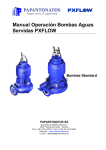
Operating instructions for PXFLOW
sewage pumps
Standard units
PAPANTONATOS SA
Roumelis & Adelfon Ntouna 1
13677 Acharnes Attiki - Greece
Tel (+30) 210 2431111 Fax (+30) 210 2431601
Internet : www.papantonatos.gr
E-mail : [email protected]
Contents
Identification plates
General description
Applications
Product description
Handling
Installation
Electrical connections
Operation
Service & maintenance
Technical data
Motor winding connection schemes
Identification plates
equipped with operating instructions for
fitting, starting, care etc. which conform to
international safety regulations.
These instructions describe the procedures
to be used for fitting, operation and
maintenance of standard submersible
waste water pumps.
Applications
This starting & operation manual are
applicable
to
the
electric
driven
submersible waste water pumps specified
on the front page. The pumps are
designed to be used for pumping raw
sewage water with solid contents. The
pumps are suitable for heavy duty
drainage applications and clean water too.
The manufacturer guaranties that the new
pump airborne noise level do not exceed
70 db(A) when submerged. For dry
installation the corresponding level is
75 db(A). Be aware that under wrong
operated duty points, noise level might be
higher.
Caution! This range of pumps is
forbidden to handle in flammable liquids
nor used in explosive environment.
Do not start the pump if any parts
belonging to the pump are missing.
WARNING! If humans should be in
contact with the pumped liquid e.g.
construction sites, lifting stations etc. a
grounded connection including an earth
leakage detector must be used.
Motor protection
All stators except PX0 are equipped with 3
built-in thermal switches and are
o
connected in series which opens at 135 C
o
and closes at approx 90 C and are
marked F1 & F2 control cable. To maintain
warranty on the pumps, these thermal
switches must be connected in series to
control circuit of control panel.
Cooling system
Models PX0, PX1 are cooled under
operation by the surrounded liquid and
cannot be installed as dry pit installation.
Models PX2, PX3 are standard equipped
with a closed internal cooling system in all
3 types of installation.
However if ordered without closed internal
cooling system cannot be installed as dry
pit
The closed internal cooling system
functions as follows:
An internal impeller, located between the
two mechanical shaft seal, circulates the
cooling liquid in a closed loop through
channels to a cooling jacket surrounding
the stator housing.
Thus the heat generated by the motor, is
transferred to the cooling liquid and finally
dissipated to the pumped liquid via a
cooling flange (heat exchange), without
any physical contact by the pumped
sewage media.
Coolant: 70% water and 30% propylene
glycole
Moisture sensor
Never install the pumps in swimming
pools, special regulations apply.
Product description
Limitations
Immersion depth to max 20m (66 ft ).
o
o
Media temperature up to 40 C (115 F ).
Higher media temperature on request.
Pump models
Example: PX3-150.X VX3 6-300
General description
The PXFLOW submersible sewage pumps
can be used in a variety of residential,
commercial and industrial applications such
as:
x
Sewage System
x
Flood and Pollution control
x
Dewatering / Effluent
x
Farms
x
Hospitals
x
Trailer Courts
x
Hotels
PXFLOW pumps are subjected to a thorough
inspection before leaving the factory and
1
PX3 : indicate module range
150 : standard outlet discharge in mm
X
: indicate version of volute
V
: Vortex impeller or
C
: Channel impeller
X
: indicate version of impeller, more
than one X can appear to indicate
other types.
3
:Family pumps
6
: number of poles (rpm)
e.g. 6=960 rpm
300 : diameter of impeller in mm
Motor
3 phase squirrel cage induction motor for
50 Hz, degree of protection IP68
Insulation class :F Standard, H Optional
All pumps except PX0 and PX1-65.0 are
supplied with a moisture sensor.
The humidity probe is made of aluminum
and is placed at the oil chamber and
connected in the upper part of stator
housing. By this design water is detected
in two compartments (oil chamber and
cable terminal board) by one sensor.
In the control cable the moisture winding is
marked D. The control cable should be
connected to a relay (optional) in the
control panel, which is activated by a
decrease in resistance to ground. Set the
alarm between 20 - 100 kOhm. Voltage
output applied to the moisture cable 12 24 V AC
Power Cable
The pumps are standard equipped with
10m electric cable of the type H07RNF. If
longer cable is required, voltage drop must
be taken in consideration. Standard cable
dimension is given on the 4th page of this
manual.
Handling
When need of transportation, the pumps
must be stored properly. Special attention
must be taken at the cables which cannot
stand rolling heavy parts. All pumps can be
stored vertical or horizontal.
Always protect cable ends from moisture and
water too, so that no moisture will penetrate
into the cable.
WARNING! Never start up the pump
without impeller. This will damage (in a few
seconds) the O-ring that seals between the
rotor-shaft and the sleeve of the
mechanical seal cartridge. Both sleeve and
rotor shaft could also be damaged due to
excessive friction!.
Before lifting up the pump checks if the
handle on the pump is fixed. Always use the
lifting handle, do not use the cables or
discharge hose. All fixing screws and bolts
must be securely fasted before lifting. Human
injury may appear if above is not secured.
After a long period of storage the pump must
be inspected carefully. Rotate the impeller by
hand before start-up and check carefully
seals and cable entry
Installation
When installing the pump, reduce the risk of
accidents, be aware that the machine is
WARNING! The pump unit doesn’t go with
the base.
The base as also others hydraulics
accessories for the installation and the
connection of the pump with the system
can be supplied from our company.
extremely heavy and contain electrical open
wires.
Before starting the installation, secure that all
screws for the lift handle, stator and volute
fixing bolts are safety tighten.
Lifting chains, cranes etc. must always be
designed to encounter without cracked the
weight of the pump. For safety reasons never
walk under suspended load.
Discharge connection bracket DCB
Place the base elbow (DCB) at the bottom of
the sump. If one
pump is installed,
place the pump
in the center of
the tank. Fit the
guide tubes to
the upper guide
bracket so they
are
in
an
accurate vertical
and parallel position to each other.
Connect the discharge pipe to the DCB and
mount eventual the pipe with a non return
valve and gate valve which suits the flow
velocity from the pump.
The lifting tackle must be installed directly at
the point above the center of gravity of the
pump while the pump automatically will
release from the DCB (which is appropriate
shaped for this purpose) when lifted vs.
fasten on the DCB when lowered.
2
Dry pit installation
PX2 and PX3 modules can be installed dry
and so can be supplied with adjustable
support. The support consists of three legs
of telescopic type.
The suction pipe
can be connected
in either direction
by changing over
the location of the
legs. The legs
after adjusting are
fixed with two
screws to lock the
position.
Secure the legs by bolting in concrete.
The suction connection pipe can be
connected vertical under the pump. The
motor unit is easier to remove and fit in
place again if the suction pipe is equipped
with a drain valve. This can be opened
when the motor is going to be fitted or
removed.
The discharge pipe should be mounted
with a drain as well, in order to let out air
under the first start-up. Afterwards it can
be fitted with a manometer to measure the
pressure.
Before start, check carefully the cables for
defects and check the level of coolant in
the cooling jacket.
Portable version / installation
This version needs
extra
attention
while
operating.
The pump can be
supplied with a
support ring.
Place the pump on
a firm surface and
keep the cables
straight,
secure
that cable are not nipped.
WARNING! Never remove the support
ring, human contact might occur and
make injury.
WARNING! For the safety operation it
is necessary to have succeeded the
appropriate support of the pump unit as
do not have any accident mainly at the
start of the pump.
If risk of overturning, place and fit the
pump on a steel plate.
When hoses are used as discharge
connection, remember that friction losses
are higher than in a pipe and flow might be
less than expected.
Venting of the volute
After lowering the pump into a sump full of
water, an air lock may occur in the volute
and cause pumping problems. In this case,
raise the pump in the medium and then
lower it again. If necessary repeat this
venting procedure.
If the problem insists then we can drill a
hole 2-3mm on the vent’s plug.
Especially for the pumps of dry installation
it is necessary to venting them again
(when have been installed at the final
position) by the appropriate hole at the
volute of the pump.
Electrical connections
The electrical installation must be
inspected by authorized electrician before
switching-on.
Make sure that the electrical terminals or
starting equipment is installed in such way
that it cannot be flooded. The electrical
installation must apply to national
regulations.
All pumps are supplied with built-in thermal
CAUTION! All electrical equipment
must always be earthed (grounded).
This applies both to the pump and to
any monitoring equipment.
switches in the stator windings. These are
marked F1, F2 and must always be
connected in series to the control circuit of
control panel.
D is connected to a moisture sensor which
is located between the oil chamber and
stator housing. This sensor should be
connected to a conductive liquid level relay
in the control panel. An alarm should be
given in event of moist.
Your local
PXFLOW representative can supply you
with the conductive liquid level relay
(optional).
Make sure that the power supply, voltage,
and
starting
method
frequency
corresponds to the nameplate data fitted
on the pump.
The motor can operate by voltage
tolerances at +/- 5%. The motor might be
overloaded and burned out if this is
exceeded.
About power supply cable, and control
cable connections see to motor winding
connection schemes in this manual.
x
Direct online starting DOL
x
Star-Delta starting Y-ǻ
Starting equipment on the control panel,
must be provided with over current
protection sensitive to phase failure. A
3phase asymmetry control relay is
recommended, adjusted to 15% phase
asymmetry
The power supply should be fused with
low-blow fuses.
15 Starts per hour (regularly spaced) are
permitted
Replacing the power cable
If the cable has been compressed or
damaged it must be replaced to avoid
water entry.
When changing the cable always change
the rubber joint-ring too, in the entry of it.
Never change dimensions from the original
one, as water may enter the motor.
If the same cable is re-used due to any repair
work, always cut away a piece at the cable
entry in order to seal on a non compressed
cable sheath.
For safety reasons the grounded conductor
should be longer than the others, these of the
phases. If the motor cable is accidentally
wrenched off, the earth conductor should be
the last to break away from its terminal. This
applies to both ends of the cable.
Electromagnetic
EMC
Compatibility,
The pump does not generate any electric
noise EMC, which can infect on other
equipment. However, if the pump is power
supplied via frequency inverter, power cables
might need screening.
The pump apply to directive EN89/336/EEC
regarding EMC.
3
Operation
Service and maintenance
By the first start-up or after repair, check the rotate direction. At
the instant starting the motor will provide a jerk. The pump must
always obtain anticlockwise reaction.If the rotation is incorrect,
transpose two phases in the electric control panel.
CAUTION! Before maintenance and repair work, motor leads
must first be completely disconnected from the power supply.
Never work on electrical systems during a thunder storm. All work
on the electrical system may only be performed by qualified
electricians
WARNING! Before starting up the pump.
Don’t operate the pump before you verify that it has been securely
fastened and cannot be tipped over or to spin, especially during
the start up.
CAUTION! When the pump or motor section has been laid on
side, always secure it with wedges from both sides to prevent it fr
rolling away
WARNING! As the pump will pump up to 70% of the nominal flow
at wrong rotation never use the visual flow rate to determine the
rotate direction. Most times, pump creates heavy noiseand
vibration when operates at wrong rotation
CAUTION! Before undertaking any service work, make sure that
the pump is thoroughly clean, and bear in mind the importance of
observing good personal hygiene. Follow your local safety
instructions.
WARNING! Do not insert your hand or any other object into the
pump volute and impeller if any power supply is connected. Remove
physically the cable even if security devices is activated.
Be aware of the starting torque, it may be very strong depending
on the size of the pump. Do not hold the pump when checking the
rotation. The pump must be heavily supported and never started
when hanging in a chain without properly support.
Regular inspection and preventive maintenance will ensure more
reliable operation. The pump should be inspected every six
months or more often if the operating conditions are difficult. The
cable should be checked more frequently. For a complete
overhaul of the pump, please get in touch with an authorized
PXFLOW workshop or your PXFLOW dealer
Inspection
Pump section
Inspection
Action in the event of a fault.
Cables
Check that the sheath is not damaged. Check that the cables are
not kinked or nipped.
Check the cooling water level of coolant
Check that all parts are in good condition, and that bolts and nuts
are securely tightened.
Check that the parts are not worn to such an extent that the pump
performance is affected.
Check that the oil is clean and is not mixed with water. See under
“Changing the oil”.
Check that the equipment does not leak or is otherwise damaged.
Fit a new cable. Correct the fault.
Cooling water
Visible Parts
Impeller/Wear ring
Shaft seal
Hoses, pipes and
valves
Changing the oil
Change of oil is done in the same way on cooled and uncooled
pumps. Remove the plug marked “outlet” and let the old oil pour
out through the groove under the plug. Discard of any used oil in
accordance with local regulations. Fasten the plug so that the
lower but not the top O-ring gasket seals. Loosen the plug marked
“inlet” and fill up with oil and then fasten both oil plugs. Use oil
with same quality and performance as Enerpar M002, white oil.
CAUTION! In the event of inward leakage, the oil housing may be
pressurized. When removing the oil plug, hold a piece of cloth over
it to prevent oil from splashing.
NOTE! Old oil should be entrusted to an oil disposal company in
accordance with local regulation.
4
Fill up with cooling liquid.
Replace worn parts. Tighten any loose bolts
and nuts.
Adjust the wear ring.
In the event of slight leakage, change the oil.
Adjust or replace defective equipment.
5
6
3 ~ Direct on –line starting DOL
Motor connection: Ʀ
1 Power Supply Cable
+ 1 Control Cable
Color Coding
Power Supply
U
V
W
PE
Black
Brawn
Grey
Yellow
3~ Direct - on - line
starting DOL
Motor connection : ǻ
PE
F1
F2
D
Control
Black
Brawn
Grey
U
F1 F2 D
V W
U
V
W
PE
F1
F2
D
Black-1
Black-2
Black-3
Yellow
Black-4
Black-5
Black-6
Internal Connection on Motor’s Terminal Board
U1,
V1,
W1,
7
U2
V2
W2
:
:
:
Black
Red
Orange
Moisture
Color Coding
Thermal switches
1 Power Supply and
Control Cable
3 ~ Star-Delta starting Y- Ʀ
Motor connection: ǿǿǿ Ʀ
Power Supply
(cable1)
U1
V1
W1
PE
Black
Brawn
Grey
Yellow
Power Supply
(cable2)
U2
V2
W2
PE
Black
Brawn
Grey
Yellow
Control
F1
F2
D
Black
Brawn
Grey
1 Power Supply Cable
+ 1 Control Cable
Color Coding
Power Supply
Control
U1
V1
W1
PE
U2
V2
W2
PE
Black-1
Black-2
Black-3
Yellow
Black-4
Black-5
Black-6
Yellow
F1
F2
D
Black
Brawn
Grey
F1 F2 D
U1 V1 W1
U2 V2 W2
1 Power Supply and
Control Cable
Color Coding
U1
V1
W1
U2
V2
W2
PE
F1
F2
D
Black-1
Black-2
Black-3
Black-4
Black-5
Black-6
Yellow
Black-7
Black-8
Black-9
Internal Connection on Motor’s Terminal Board
U1,
V1,
W1,
8
U2
V2
W2
:
:
:
Black
Red
Orange
Moisture
Color Coding
3~ Star-Delta starting Ȋ-ǻ
Motor connection : III ǻ
Thermal switches
2 Power Supply Cable
+ 1 Control Cable
3 ~ Direct on-line starting DOL
Motor connection: With sensor PT100
1 Power Supply Cable
+ 1 Control Cable
Color Coding
Power Supply
Control
U
V
W
PE
Black
Brawn
Grey
Yellow
F0
F1
F2
Black
Grey
Brawn
D
Yellow
MAIN CABLE OF POWER SUPPLY
CABLE OF CONTROL
PE
U
V W
Internal Connection on Motor’s Terminal Board
U1,
V1,
W1,
98
U2
V2
W2
:
:
:
Black
Red
Orange
3 ~ Star-Delta Starting Y- Motor Connection: ǿǿǿ With sensor PT100
2 Power Supply Cable
+ 1 Control Cable
1 Power Supply Cable
+ 1 Control Cable
Color Coding
Power Supply
(Cable1)
Power Supply
(Cable2)
Control
U1
V1
W1
PE
Black
Brawn
Grey
Yellow
U2
V2
W2
PE
Black
Brawn
Grey
Yellow
F0
F1
F2
Black
Grey
Brawn
D
Color Coding
Power Supply
U1
V1
W1
PE
U2
V2
W2
PE
Black-1
Black -2
Black -3
Yellow
Black -4
Black -5
Black -6
Yelloy
Control
F0
F1
F2
Black
Grey
Brawn
D
Yellow
Yellow
MAIN CABLE OF POWER SUPPLY
ȡ
Ȣ
Ȣ
Ș Ȓȡ
CABLE OF CONTROL
PE
U1 V1 W1
U2 V2 W2
Internal Connection on Motor’s Terminal Board
U1,
V1,
W1,
10
9
U2
V2
W2
:
:
:
Black
Red
Orange
Roumelis & Kapodistriou
13671 Axarnes Attiki (P.O. 46546)
Tel: +30210 - 2431111,
Fax: +30210 - 2431601
web site: www.papantonatos.gr
Declaration of Conformity
We herewith declare that the following sewage pump models:
PXFLOW PX0 , PX1 , PX2 , PX3 , PX4, PXGRIND2
comply with the provisions of
98/37/EEC
89/336/EEC
73/23/EEC
The following harmonized standards are applicable:
EN 809
EN 292/1
EN 292/2
EN 50081-2
EN 50082-2
EN 60034
The User's Manual, includes important safety recommendations for transportation, storage,
installation, operation and maintenance of PAPANTONATOS SA pumps.
Athens 10 / 2 / 2008
Papantonatos SA
Panagiotis E. Stavropoulos
Quality Assurance Manager
EN ISO 9001: 2000 certified