1
Temperature detection
value
Operating ambient
temperature
(25 ± 5 °C)
Overall
Operating
ambient
accuracy
temperature (less
than 20 °C, more
than 30 °C)
Resolution
Conversion speed
(Sampling time)
Temperature input point
CC-Link station type
AJ65BT-64RD3
3-wire
AJ65BT-64RD4
4-wire
Pt 100, JPt 100
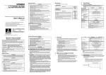
4. Name of Each Part
1 mA
–180 to 600°C
16-bit signed binary : –1800 to 6000
(value to one decimal place × 10)
32-bit signed binary : –180000 to 600000
(value to three decimal places × 1000)
The name of each part in the AJ65BT-64RD is described.
2)
MITSUBISHI
± 0.1 % (accuracy for maximum value)
B RATE STATION NO.
X10
X1
MELSEC A J65BT-64RD
SW
0
1-4
9
MODE
NORMAL
TEST CH.
TEST
9) (Side face)
1)
PW
RUN
L RUN
SD
RD
L ERR.
01
2
3
4
01
901
2 8
2
3 7
3
654
654
MODE OFFSET UP
901
2
3
4
± 0.25 % (accuracy for maximum value)
RESET
SET
GAIN DOWN
9.5
(0.37)
JPt 100 Pt 100
63 (2.48)
Item
Measurement method
Connectable platinum
temperature-measuring
resistor
Output current for detecting
temperature
Temperature input range
6.2 Precautions when Wiring
To obtain maximum performance from the functions of AJ65BT-64RD and
improve the system reliability, a wiring with high durability against noise is
required.
The following describes the external wiring precautions.
(1) Use separate cables for the AC and the external input signals of the AJ65BT64RD, in order not to be affected by the AC side surge or conductivity.
(2) Always place a platinum temperature-measuring resistor at least 10 cm (3.9 in.)
apart from the main circuit line and AC control circuit line. Place a platinum
temperature-measuring resistor sufficiently apart from circuits with high
frequency, such as high-voltage lines and inverter load main circuits. If they are
placed close to each other, the platinum temperature-measuring resistor is
influenced more easily by the noise, surge, or conductivity.
NP
2- ø4.5 installing hole
MITSUBISHI
B RATE STATION NO.
X10
X1
MELSEC AJ65BT-64RD
6.3 Connecting to the AJ65BT-64RD3
SW
0
1-4
9
(1) The highest accuracy can be obtained if a 3-wire type platinum temperaturemeasuring resistor is used for AJ65BT-64RD3.
The following shows a connection example of a 3-wire type platinum
temperature-measuring resistor.
MODE
NORMAL
TEST CH.
TEST
PW
RUN
L RUN
SD
RD
L ERR.
01
2
3
4
01
901
2 8
2
3 7
3
6 54
654
MODE OFFSET UP
9 01
2
3
4
SET
GAIN DOWN
RESET
56 (2.2)
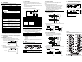
3.1 Performance Specification
The performance specification of the AJ65BT-64RD is shown below.
And, refer to master module user's manual which is used about the general
specification.
7. External Dimensions Diagram
3.3 Applicable Systems
The CC-Link system master modules that the AJ65BT-64RD can use are
explained below.
y There are no restrictions when using the Q series master modules (QJ61BT11N,
QJ61BT11).
y When using the Q series master modules (AJ61QBT11, A1SJ61QBT11), use one
where the symbol shown below (9707 B or later) is recorded in the DATE column
on the rating name plate. The master modules that do not have "9707 B" recorded
on the DATE column cannot be used.
65 (2.56)
3. Specification
0.025°C
142.9 (5.63)
40 ms/channel*1
4-channel/module
Remote device station
4-station : RX/RY
128 points each
Occupied points
RWw/RWr
16 points each
Connection cable
CC-Link dedicated cable
Between batch power supply system and ground
Between batch power supply system and batch communication
system
Dielectric withstand voltage
Between batch communication system and batch temperature input
Between batch temperature input and ground
500 V AC, 1 minute
Between the platinum temperature-measuring resistor input and CC-Link
transmission : photocoupler insulation
Insulation method
Between the platinum temperature-measuring resistor input and channel :
no insulation
Between batch power supply system and ground
Between batch power supply system and batch communication
system
Between batch communication system and batch temperature
Insulation resistor
input
Between batch temperature input and ground
500 V DC, more than 10 M Ω by the insulation resistance taster
Noise durability
Noise voltage 500 Vp-p, Noise width 1 μs by noise simulator of the
noise frequency 25 to 60 Hz
Connection terminal block
27 points terminal block (M 3.5 × 7 screws)
Supported cable size
0.75 to 2.00 mm2
Supported solderless terminal
RAV 1.25-3.5, RAV 2-3.5 (Conforms to JIS C2805)
Module mounting screw
M4 × 0.7 mm (0.03 in.) × 16 mm (0.63 in.)
Installation in the rail is possible, too.
Applicable DIN rail
TH35-7.5Fe, TH35-7.5Al, TH35-15Fe (conform to JIS C 2812)
External power supply
24 V DC (18 to 30 V DC)
Allowable momentary power
1 ms
failure period
Weight
0.38 (0.84) kg (lb.)
*1 Conversion speed is the time until it is converted to the corresponding digital value
after the temperature has been input, and then stored in the remote register.
When the multiple channels are used, the conversion speed is “40 ms × number
of the conversion enable channels
3.2 Specifications when Connecting to a Platinum TemperatureMeasuring Resistor
The following explains the specifications when connecting the AJ65BT-64RD
and a platinum temperature-measuring resistor.
(1) AJ65BT-64RD3
• The effect on the measured resistance by the discrepancy in the lead
resistance value connected to A, b is approximately 0.025 °C/10 m Ω.
• The lead resistance value between platinum temperature measuring resistor
and AJ65BT-64RD3 should be 100 Ω or less per line.
100 Ω or less per line
A
8)
Number
1)
2)
3)
4)
5)
6)
7)
8)
9)
7) 3) 4) 5) 6)
Name
Station setting switch
Transmission baud rate setting switch
MODE switch
OFFSET/GAIN (Offset/gain) setting switch
UP/DOWN switch
RESET switch
LED for operation status display PW
RUN
L RUN
SD
RD
L ERR.
Terminal block
Platinum temperature-measuring resistor type specification pin
5. Handling
151.9 (5.98)
Unit: mm (in.)
*1 May be better to connect depending on the operating environment.
(2) A 4-wire type or 2-wire type platinum temperature-measuring resistor can also be
used for AJ65BT-64RD3.
Connect as shown in the diagrams below when using a 4-wire type or 2-wire type
platinum temperature-measuring resistor.
4-wire type
2-wire type
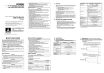
5.1 Handling Precautions
(1) Because it is made of resin, do not drop or given a strong shock to the module
case and the terminal block.
(2) Do not take the printed circuit board of the module out of the case. It may result
in a failure.
(3) Be careful not to let foreign matter such as filings or wire chips get inside the
module while wiring. Remove all foreign matters if any get inside.
(4) Tighten the module mounting screws within the following torque range.
Screw area
Module mounting screws (M4 screw)
Terminal block terminal screws (M3.5 screw)
Terminal block mounting screws (M3.5 screw)
Tightening torque range
0.78 to 1.18 N · m
0.59 to 0.88 N · m
0.98 to 1.37 N · m
(5) When using a DIN rail adapter, install the DIN rail considering the precautions
described below.
(a) Applicable DIN rail types (conform to JIS C 2812)
TH 35-7.5 Fe
TH 35-7.5 Al
TH 35-15 Fe
(b) Space between DIN rail mounting screws
When installing a DIN rail, tighten the screws with a space of less than 200 mm
(7.9 in.).
A
A
B
B
b
b
SLD
SLD
WARRANTY
Mitsubishi will not be held liable for damage caused by factors found not to be the cause of
Mitsubishi; machine damage or lost profits caused by faults in the Mitsubishi products; damage,
secondary damage, accident compensation caused by special factors unpredictable by Mitsubishi;
damages to products other than Mitsubishi products; and to other duties.
6.4 Connecting to the AJ65BT-64RD4
(1) The highest accuracy can be obtained when if a 4-wire type platinum
temperature-measuring resistor is used for AJ65BT-64RD4. The following
shows a connection example of a connecting the 4-wire type platinum
temperature-measuring resistor.
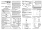
6. Wiring
6.1 Wiring Example with CC-Link Module
Platinum temperaturemeasuring resistor
B
The twisted cable connections between the AJ65BT-64RD and master
module are as follows:
b
SLD
(2) AJ65BT-64RD4
The lead resistance value between between platinum temperature-measuring
resistor and AJ65BT-64RD4 should be 100 Ω or less per line.
*1 May be better to connect depending on the operating environment.
(2) A 4-wire type or 3-wire type platinum temperature-measuring resistor can also be
used for AJ65BT-64RD4.
Connect as shown in the diagrams below when using a 3-wire type or 2-wire type
platinum temperature-measuring resistor.
3-wire type
2-wire type
100 Ω or less per line
a
A
Point
Platinum temperaturemeasuring resistor
B
b
SLD
For the modules at both ends of the data link, make sure to connect the "terminal
resistor" that is attached to a master module (Connect between DA and DB).
a
a
A
A
B
B
b
b
SLD
SLD