1
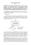
WAFER GSM-TP Temperature&Humidity Monitor and Alarm
WAFER-TP Series GSM Remote type
Temperature & Humidity Monitor and Alarm
User Manual
For TP02B
Supplied by: Shanghai Wafer Microelectronics Co.,Ltd.
Address: Room.23E, LiangFeng Building, NO.8, DongFang Road, Shanghai, China
Web: http://www.waferstar.com
Email: [email protected]
Tel: +86-(0)21-5187-0528
Fax: +86-(0)21-5045-4820
http://www.waferstar.com
WAFER GSM-TP Temperature&Humidity Monitor and Alarm
Introduction for WF-TP series:
The WAFER temperature and humidity alert and monitoring solution allows the user to pre-set a
temperature and humidity range and receive an alert (via SMS, phone call, email) if the current
data exceeds the pre-set range.
An email log is also supported, allowing emailing of temperatures and humidity data once an
preset timer from readings taken at preset minute intervals (settings are user configurable) prior to
the sending the temperature data-log to the configured email address.
The WAFER device is controlled via the use of SMS command messages, these are standard text
messages sent from a mobile phone which are formatted in a specific way to configure the device
(i.e. change GPRS settings).
Functions include:
Remote temperature reporting of site equipment
Logging of temperature data in remote locations via email
Over/under temperature alarm notification via SMS and phone call or email.
Instantaneous temperature reading via status SMS
Features:
Frequency Band: Global Quad Band GSM/GPRS Engine ( 850/900/1800/1900MHz )
Dimensions:
153 mm x 66 mm x 28 mm
Weight:
385g
Supply Voltage:
AC/DC12V
Order description:
Order type
TP01
TP01A
TP02
TP02B
Temperature Sensor Input
1
1
2
2
Humidity Sensor Input
0
0
1
1
Email Log Function
NO
YES
YES
YES
Output Numbers
4
4
4
4
Maximum WHL Number
2
2
2
19
Sensor compatible:
Sensor model
Humidity Range Sensitivity
DS18B20
AM2301/DHT21 0-100%RH
±3%RH
AM2305
0-100%RH
±2%RH
Temperature Range
-55~125℃
-40~80℃
-40~120℃
Sensitivity
±2℃
±0.5℃
±0.3℃
http://www.waferstar.com
WAFER GSM-TP Temperature&Humidity Monitor and Alarm
Installation:
To install the GSM-TP Device, You should make sure that GSM-TP is installed in a place
where there is GSM signal coming from the operator you want to use. Check it with a phone
before proceeding with the installation. If you
need to install the device in a place with little
signal, you may consider using an external
antenna that we may supply as an option to
be purchased separately with 50cm cable.
You should then insert the SIM Card of
the operator you want to use with the right
direction as the left picure.
!Note! : You must remove the PIN
request from the SIM before inserting it in
the
unit, otherwise the device will not work. In order to do so, insert the SIM in a phone and
disable the PIN request (usually there is a security menu that enables you to do so).
CONNECTORS DESCRIPTION
On the side panel of Wafer GSM-TP,it has
GSM Antenna Connector, Sensor Input
Connector, SIM Card holder,Program
Adapter.
Also it has the Status LED,that is used to
show the GSM connection status, SMS
receiving status and other working status.
RELAY OUTPUT TERMINAL
GSM-TP also comes with additional 4
Outputs.The outputs can be controlled
throught the phone calling or the SMS
command.
Each output can be switched Permanently or
Temporarily with the SMS Command
Only Output1 can be switched Permanently
or Temporarily with the phone calling.
http://www.waferstar.com
WAFER GSM-TP Temperature&Humidity Monitor and Alarm
Connect or Disconnect the SENSOR
Connect the sensor to the GSM-TP controller. The left picture is to shows how to mount the
sensor.that is easy to mount the sensor,just use the hand from the end to mount the sensor.
And the right picture shows how to disassemble the sensor.
( You should mount or disassemble the sensor according to the picture. Don’t mount or
disassemble the sensor with big force,that would damage the sensor connector. )
Wafer GSM-TP Programming:
You can program the GSM-TP with SMS commands using your phone. It is safe to do so
because in addition to the fact that other people may not know the number of the SIM inserted in
it, we also use a Password that makes it impossible for anybody who doesn't know it to access the
system by chance.
Remember that commands must be CAPITAL LETTERS. It is PWD not pwd, CAP not Cap
etc. Don't add spaces or any other character.
Some complicated Instructions,that cann’t be programmed by the phone SMS. That would
need to use the PC software to program and inquire the status of the terminal.
The bellow wire picture is to show how to connect the cable to the PC program connector
with the Program adapter.Please connect it in the right direction with the picture.
Simple RS232 program card ( Standard )
USB program adapter box (Optional Parts)
http://www.waferstar.com
WAFER GSM-TP Temperature&Humidity Monitor and Alarm
Program SMS Command for WF-TP02B:
CONNECT
(this SMS command is used to test the device easily,no need pasword)
Reply format: [Device name][Sensor-T1 name][ Sensor-T1 name] [ Sensor-H name]
Example Reply:WEIFANG*Garden*Home temperature*Home humidity
SMS PASSWORD
Allows setting of a new password.
The password is required in all SMS command messages sent to the unit. The default
password is 123456
Format:
#PWD[smspassword][new_password][new_password]
Example: #PWD123456#CAP121212#CAP121212
Reply:
PWD SETUP OK
WHL
This command is used to add or remove numbers that are enabled to control the device.
You can add up to 2 numbers in the list.
• To add a number, the syntax of the command is the following:
Format:
#PWD[smspassword][WHL ID]=[Phone Number]
Example: #PWD123456#WHL01=61143815
Reply :
WHL001 SET TO 61143815 OK
Where 01 is the position in the list and 61143815 is the number enabled.
Please note that it is possible to program up to a maximum of 16 digits for a number.
• To check which is the number in a place of the list:
Format:
#PWD[smspassword]#WHL=ALL?
Example: #PWD123456#WHL=ALL?
Reply :
WHL1=18017370819,WHL2=0000,ALERT=13564121668
NAME
Setting of the WAFER unit name used to identify the WAFER unit when events (alarms /
logs) are sent.
Format:
#PWD[smspassword]#NAME:[name]
Example: #PWD123456#NAME:Server Room1
REPLY:
DEVICE NAME IS Server Room1
SENSOR Config
Set sensor_no/min temp/max temp/report type/alias.
Format:
#PWD[smspassword]#SENSOR-[sensor_no][min][max][alert_type][sensor name]
a) Sensor_no: SENSOR-T1,SENSOR-T2 or SENSOR-H
b) Mini temp & max temp are in degrees Celsius. The format must be as follows:
a. -/+xxx.x (numbers only)
b. Example: -12.3°C is denoted by -012.3
http://www.waferstar.com
WAFER GSM-TP Temperature&Humidity Monitor and Alarm
c. Example: +5.4°C is denoted by +005.4
Mini humidity & max humidity are from 0 to 100 (0% to 100%)
c) Report_type Type: This consists of the following:
a. Both = Alert will be sent if temp goes outside safe limits and alert will also
be sent if temp falls back within the safe limits.
b. OUT = Alert will be sent if the temp goes outside min & max settings.
No alert will be sent if the temp falls back into the safe limit.
c. IN =
Alert will be sent if the temp falls inside the min and max settings.
d. Sensor name: This allow you to give the sensors a name.
Examle:
#PWD123456#SENSOR-T1#MIN-001.5#MAX+005.5#OUT#SERVERROOM
#PWD123456#SENSOR-T2#MIN+010#MAX+050.5#IN#GARDEN
#PWD123456#SENSOR-H#MIN20#MAX80#BOTH#ABCRROOM
REPLY: SENSOR-T1#MIN-001.5#MAX+005.5#OUT#SERVERROOM OKAY
REPLY: SENSOR-T2#MIN+010#MAX+050.5#IN#GARDEN OKAY
REPLY: SENSOR-H#MIN20#MAX80#BOTH#ABCRROOM OKAY
TEMPERATURE DATA at F or C Config
#PWD123456#TEMP-DEGREE=F
REPLY:
Temperature degree is setup to Fahrenheit
#PWD123456#TEMP-DEGREE=C
REPLY:
Temperature degree is setup to Centigrade
GPRS Setting
Allows settings of the GPRS APN, username, and password for the SIM card. These are
obtained from the SIM card provider.
Format:
#PWD [smspassword]#GPRS:[APN name][username]#[password]
Example: #PWD123456#GPRS:CMNET#abaad#sddss
REPLY:
GPRS SETUP OK
(Sometimes,with the SIM card,that APN name is fixed,and no need to config the user
name and password,then we only use:
#PWD123456#GPRS:CMNET##
Note: CMNET is the APN name)
GPRS Test
Check the GPRS setting
Format:
#PWD[smspassword]#GPRS?
Example: #PWD123456#GPRS?
REPLY:
GPRS:CMNET##
EMAIL Parameters Config
Setup the email sever parameters:
Format:
#PWD[smspassword]#SMTP:[SMTP]#POP3:[POP]
account]:PASS:[email password]
#ACCOUNT:[email
http://www.waferstar.com
WAFER GSM-TP Temperature&Humidity Monitor and Alarm
Example:
#PWD123456#SMTP:smtp.163.com#POP3:pop3.163.com#ACCOUNT:fclmyl2#PAS
S:565621321
LOG INTERVAL and LOG TIMER
• Log data save timer and the Log data send timer setting
a) log_repeat: Interval in which the temperature is recorded in seconds (30 to 86400
seconds).
b) log_send: Number of temperature readings (1 to 500) after which the log is
emailed.
Format:
#PWD[smspassword]#LOGINTERVAL[log_repeat]#LOGSEND[log_send]
Example: #PWD123456#LOGINTERVAL60#LOGSEND100
REPLY:
LOG INTERVAL IS 60 SECONDS AND RECORD LIST IS 100
Will record the temperature every 60 seconds and then after 100 logs, the WAFER will
email the log of 100 records.
• Log Interval checking
Format:
#PWD[smspassword]#LOGINTERVAL?
Example: #PWD123456#LOGINTERVAL?
REPLY:
LOGINTERVAL IS 0120,LOGSEND IS 20
LOG NOTIFY
Log information only can be sent through EMAIL
Format:
#PWD[smspassword]# NOTIFYLOG# EMAIL:[Email address]
Example: #PWD123456#NOTIFYLOG#EMAIL:[email protected]
REPLY:
NOTIFYLOG EMAIL IS [email protected]
LOG email Function close
This command is used to close the email Log report function and ON or OFF the ALERT
Format:
#PWD[smspassword]# NOTIFYLOG=OFF,ALART=ON:SMS
Example: #PWD123456#NOTIFYLOG=OFF,ALERT=ON:SMS
REPLY:
NOTIFY LOG FUNCTION IS OFF,ALERT IS ON:SMS
LOG TEST
This command is used to check the LOG setting parameters.
Format:
#PWD[smspassword]#LOG?
Example:#PWD123456#LOG?
REPLY:
LOG-SETTING=ON*GPRS=OK*EMAILSETTING=OK*LOGINTERVAL=0120*LOGSEND
=60*LOGNOTIFY=OK
(LOG test command need more time around several minutes to finish the
command, so you need to wait and don’t send more command before get the reply
message)
SENSOR ALERT
http://www.waferstar.com
WAFER GSM-TP Temperature&Humidity Monitor and Alarm
Set the alert notify medium:Email or SMS or Phone call
Format:
#PWD[smspassword]# NOTIFYALERT#[Method]
Example: #PWD123456#NOTIFYALERT#email: [email protected]
REPLY:
NOTIFYALERT EMAIL IS [email protected]
Example: #PWD123456#NOTIFYALERT#SMS:+441111111111
REPLY:
NOTIFYALERT SMS IS +441111111111
Example: #PWD123456#NOTIFYALERT#CALL:+441111111111
REPLY:
NOTIFYALERT CALL IS +441111111111
SENSOR ALERT INTERVAL
This command is designed to send repeated alerts to the alert contact list if the
temperature or humidity is kept in alert status for interval time.
Set alert repeat / min alert interval
a) alert_repeat: The intervals at which the alarm is repeated
For no repeat alert set to 0.
b) alert_interval: Delay for the alert information is kept to send the alerm information
Format:
#PWD[smspassword]#REPEAT[alert_repeat]#INTERVAL[alert_interval]
Example #PWD123456#REPEAT3000#INTERVAL120
REPLY: REPEAT SET TO 3000,INTERVAL SET TO 120
SENSOR ALERT
This is used to turn on the alert or off the alert function
Select the alert information through SMS or Email or Call
Format:
#PWD[smspassword]#ALERT=ON:[CHANNEL]
Example: #PWD123456#ALERT=ON:SMS
#PWD123456#ALERT=ON:EMAIL
#PWD123456#ALERT=ON:CALL
#PWD123456#ALERT=OFF
REPLY: ALERT IS SMS
SENSOR ALERT TEXT
This is used to setup the alarm text for the sensor alert
Format:
#PWD[smspassword]#[ALERT]:[ALERT TEXT]
Example: #PWD123456#ALARM-OUT-TEXT:Server Room1 maximum alarm
#PWD123456#ALARM-IN-TEXT:Server Room1 in alarm
REPLY:
ALARM-OUT-TEXT IS Server Room1 maximum alarm
ALARM-IN-TEXT IS Server Room1 in alarm
SENSOR ALERT CHECK
This command is used to check the ALERT setting parameters.
Format:
#PWD[smspassword]#ALERT?
Example: #PWD123456#ALERT?
REPLY:
ALERT-SETTING=ON*SMS:1828038338*ALERTINTERVAL=0180*ALERTREPEAT=60
http://www.waferstar.com
WAFER GSM-TP Temperature&Humidity Monitor and Alarm
INPUT ALERT
After the input port is shorted or disconnect more than 2 seconds,then would trigger the
alarm
INPUT ALERT TEXT
#PWD123456#ALERT-INPUT1-TEXT-ON=alarm1 on information
#PWD123456#ALERT-INPUT1-TEXT-OFF=alarm1 off information
#PWD123456#ALERT-INPUT2-TEXT-ON=alarm2 on information
#PWD123456#ALERT-INPUT2-TEXT-OFF=alarm2 off information
STATUS
This will retrieve the current temperature readings and send the data via SMS to the
number this originated the request.
Format:
#PWD[smspassword]#status?
Example: #PWD123456#STATUS
REPLY:
MINT1-001.5,#MAXT1+005.5,TEMP1+20:MINT2-001.5,#MAXT2+005.5,Temp2:+20,
MINH10, MAXH80,HUMIDITY40
RELAY WORKING
#RLY
Temporary latching of output relays
This command allows the temporarily switch on the Relays for up to 65,000 seconds and
receive confirmation SMS text alerts when the Relays switch on and off
This command does not affect the #GOT1 or #GOT2 settings
For example: To activate relay 1 for 60 seconds you would send the following SMS text
message to the unit
#PWD123456#RLY1=00005
Where RLY1 indicates the relay number (From 1 to 4) and 0005 is the time in seconds
and should be entered in a 5 digit format as shown
The administrator number will receive the following confirmation text message from the
unit
#RLY1-ON: 05
when the relay 1 switches on, the administrator number will receiver the following
message when the relay switches off
#RLY1-OFF
The confirmation SMS text messages are only sent to the administrators who are active in
the relay.
For example: To switch on relay 2 for 360 seconds and the administrator number would
send the following SMS text message to the unit
#PWD123456#RLY2=00360
Where 2 indicates relay 2 and 03600 is the on time in seconds, this should be entered in a
5 digit format as shown
http://www.waferstar.com
WAFER GSM-TP Temperature&Humidity Monitor and Alarm
The administrator number will receive the following confirmation from the unit
#RLY2-ON: 00360
when relay 2 switches on, the administrator number will receiver the following
confirmation when the relay switches off
#RLY2-OFF
The confirmation SMS text messages are only sent to the administrators who are active
the relay
#RLOP
Switching Relay permanently on and off
It is possible to switch four relays either on or off using the #RLOP commands
To switch Relay 1 permanently on you would send the following SMS text message to the
unit.
#PWD123456#RLOP1=ON or OFF ( RLOP2,RLOP3,RLOP4 is the same command )
You will receive the following confirmation from the unit
RLOP1 ON OK when the relay switches on
RLOP1 OFF OK When the relay switches off
The confirmation SMS text messages are only sent to the administrators who are active in
the #RERN list
PHONE CALLING
#MODE
Relay Operation Mode selection (Phone calling mode)
This command allows user to control the Relay with pulse mode or switch mode
MODE0: Pulse mode (Momentary Relay pulse)
MODE1: Switch mode (Ratchet Relay)
Example: #PWD123456#MODE0
REPLY:
RELAY SET TO MODE0
Example: #PWD123456#MODE1
REPLY:
RELAY SET TO MODE1
#GOT Gate pulse delay time
When setup the GOT Timer,
First you need to setup the timer multiplier at millisecond or second or minutes.
Example: #PWD123456#TIMER-DELAY-AT-MILLISECOND
Example: #PWD123456#TIMER-DELAY-AT-SECOND
Example: #PWD123456#TIMER-DELAY-AT-MINUTE
REPLY:
TIMER-DELAY-AT IS MILLISECOND
REPLY:
TIMER-DELAY-AT-SECOND
REPLY:
TIMER-DELAY-AT-MINUTE
Then you need to setup the GOT timer number:
This command is useful in case you need to keep the button pressed longer. The
standard time is 0,3 seconds (300 ms). You can change it with the GOT command.
• The syntax of the command is the following:
Example: #PWD123456#GOT500
http://www.waferstar.com
WAFER GSM-TP Temperature&Humidity Monitor and Alarm
REPLY:
DELAY TIME SET TO 0500MS
With the above command the opening time has been set to 500 ms (0,5 seconds).
• You can check what the current pulse time is with the command
Example: #PWD123456#GOT?
REPLY:
DELAY TIME IS 0500 MS
http://www.waferstar.com
WAFER GSM-TP Temperature&Humidity Monitor and Alarm
Quick Start Guide
Connect the device to the GSM net
1.
Insert the SIM Card
Press the right yellow button to eject the SIM card holder out, then put the SIM card inside
the holder, then Push the SIM card fully into the slot.
2. Connect the Antenna
Screw the antenna clockwise into the round connector, with the antenna pointing upwards. Do
not over-tighten the nut.
4. Connect the temperature and humidity sensor
3. Connect the Power adapter
Connect the power supply plug to your power outlet and switch on.
4. Confirm that you have a GSM Signal
After the GSM-TP has been switched on,firstly the RED LED will flash 1 flasch every one
second, after a few seconds ,after GSM succefully is connected ,then the Green LED and RED
LED will start to flash together.
GSM connection to the network for SMS,then Move to Step 5.
If No GSM connected,then try to relocate the device to an area with GSM coverage. Or use a high
gain antenna (please contact us for details). Do check that your SIM card is working in the chosen
location of the WAFER by fitting it into a GSM mobile phone first.
5. SMS Setup
To confirm that your GSM-TP unit is set up and working successfully on the GSM network, send
the following text message from your mobile phone.
Message:
CONNECT
Reply:
Device name and sensor name
Example reply: WEIFANG*Garden*Home temperature*Home humidity
Now we’ll add a useful configuration to the GSM-TP:
The following set up will add an SMS alert on temperature sensor 1 called “Server Room” to
be sent via SMS to the phone number “00447770111111”
An alert SMS will be sent if the temperature falls below, in this case, 15°C or exceeds 25°C..
Send these SMS text messages to configure your GSM-TP:
#PWD123456#SENSOR-T1#MIN+10.5#MAX+25.0#OUT#Server Room
Then send a separate SMS, replacing the mobile phone number below with your own:
#PWD123456#NOTIFYALERT#SMS: 00447770111111
Then switch on the alert function to the SMS
#PWD123456#ALERT=ON:SMS
If you want to use the email to send the alert or send the data Log,then firstly you need to config
the GPRS data, Email Config
#PWD123456#GPRS:CMNET#abaad#sddss
#PWD123456#SMTP:smtp.163.com#POP3:pop3.163.com#ACCOUNT:fclmyl2#PASS:56562121
#PWD123456#NOTIFYLOG#EMAIL: [email protected]
(Email for Log information)
http://www.waferstar.com
WAFER GSM-TP Temperature&Humidity Monitor and Alarm
#PWD123456#NOTIFYALERT#email: [email protected] (Email for Alert information)
Then setup the Log data save timer and the Log data send timer setting
#PWD123456#LOGINTERVAL60#LOGSEND100
After setting ,you need to check the GPRS and Log email setting is working,then send the folling
SMS:
#PWD123456#LOG?
Then you will get the REPLY SMS:
LOG-SETTING=ON*GPRS=OK*EMAILSETTING=OK*LOGINTERVAL=0120*LOGSEND
=60*LOGNOTIFY=OK
You should check the parameter of LOGNOTIFY should be OK,then
In your LOG email box would receive a LOG test email.
If the LOGNOTIFY=NOT, then you need to check your parameters setting according to the reply.
For extended SMS configuration, please refer to the GSM-TP SMS command.
http://www.waferstar.com
WAFER GSM-TP Temperature&Humidity Monitor and Alarm
Troubleshooting
No LED is on after power up
· Check the power supply.
GSM Green LED is not flash,only flash the RED LED slowly
· GSM Signal is not good and cann’t register to GSM
· Check the SIM card.
· Check the PIN.
· Check the antenna connection.
· Select a place with a good GSM signal.
No SMS reply,after SMS command send to device
· Try to send the test SMS command: “ CONNECT ” to the device
· When send out the SMS, then check the Green LED would quick flash around five times,that
means device can accept the SMS.
· After Green LED quick flash five times,then would followed the slow flash five timers,that
means device send out the SMS
· If no LED flash,then check the GSM signal
Cnn’t get the LOG data from email
· Check the GPRS setting is properly
· IF your SIM card can use the GPRS.
· Check the emil address is right
· Check the LOG interval save timer and send timer is setting properly
· Check the LOG sending function is enabled
· Use the Self-test SMS command: “#PWD[password]#LOG? ” to sort the problems
Cnn’t get the Alert data at my mobile phone
· Check if the temperature or humidity is out of the alert range
· Check the alert phone number list is right or not
· Check the interval and resend timer is properly
· Check the alert direction IN or OUT is properly
· Use the Self-test SMS command: “#PWD[password]#ALERT? ” to sort the problems
No tone can be heard after line off-hook
· Check the telephone line connection.
· GSM-TP is not initialized properly upon start (approx. 10s after power up).
· GSM-TP is not supplied with power.
http://www.waferstar.com
WAFER GSM-TP Temperature&Humidity Monitor and Alarm
This brochure provides an overview of the products and services of WEIFU GSM
Modules, For further information and queries kindly contact:
Email: [email protected]
Web: www.waferstar.com
Tel:
0086-21-51870528
Also accessible via our online MSN service: [email protected]
Copyright 2013, WEFU GSM
V2013-0310V1.0
http://www.waferstar.com