1
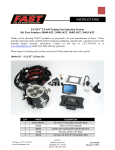
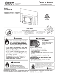
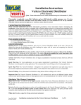
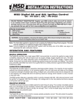
Atomic EFI PN 2900 - Master Kit with Throttle Body and Fuel Pump Kit PN 2910 - Throttle Body Kit ONLINE PRODUCT REGISTRATION: Register your MSD Atomic EFI online and you’ll be entered in our monthly 8.5mm Super Conductor Spark Plug Wire give-away! Registering your product will help if there is ever a warranty issue with your product and helps the MSD R&D team create new products that you ask for! Go to www.msdperformance.com/registration. Thank you for selecting the Atomic EFI throttle body conversion kit from MSD! The Atomic EFI is designed to replace 4-barrel carburetors to create smoother, more reliable street driving. As with any performance product, please be sure to read the entire instruction manual before attempting to install this system on your vehicle. The MSD Customer Support phone lines are available 7am-5pm Mountain Standard Time Monday through Friday to answer any technical questions you may have in regards to installing the Atomic EFI or other MSD parts (915) 855-7123. Parts Included: 1 - Throttle Body w/ECU 1 - TB Harness - Points, Ign. Driver, AC 1 - Power Module 1 - PM Harness - w/ WBO2 1 - Handheld Monitor 1 - Coolant Temp Sensor Parts Bag 1 - O2 Sensor 1 - O2 Bung and Plug 4 - Rubber Grommet 4 - Eyelet Insert 4 - Mounting Screws 1 - 4G Micro SD Card 4 ft. CAN Extension Air Filter Gasket Intake Manifold Gasket 1 - Fitting 6AN Adapter 6 Male With Fuel Pump Kit: PN 2920 1 - Fitting-6AN-90° 5 - Clamps, Fuel Line 1 - Clamp, Post Filter 1 - Self Tapping Screw 1 - Fuel Pump 1 - Filter-Post 15 ft. Fuel Line 2 ft. Black Wire 14g Ring Lug Note: The Atomic EFI requires an isolated 12 volt square wave signal to trigger the injection. An MSD Ready-to-Run Distributor (with tach output lead) or a CD ignition such as an MSD 6 Series Ignition Control. CAPABILITIES The Atomic EFI throttle body fits a standard square bore intake manifold flange. If your intake manifold does not currently match this description, adapters and/or intakes are available for most popular engines. The Atomic EFI Master Kit (PN 2900) is capable of supplying fuel to engines with 100-525 HP at the crank. If your engine makes less than 100 horsepower there may be idle issues as the system will struggle to compensate for such small needs. If your engine makes more than 525 horsepower this system could limit the engine due to fuel starvation. For engines producing 525-625 horsepower MSD offers a fuel system upgrade that will support the additional needs of such engines. The Atomic EFI is a self-tuning fuel system that continuously adjusts after the basic configuration is complete. There is no laptop programming. Based on the engine descriptors you input, the Atomic will automatically create a base fuel map to get the engine running. Once running, the self learning system will adjust those maps to get the engine exactly where you want it. If you change altitude, outside temperature, or other factors the Atomic will adjust accordingly, on the fly. This feature ensures that your engine will have the right fuel mixture at all times, even if you drive from the sunny coast to the cold mountains. M S D • WWW.ATOMICEFI.COM • (915) 857-5200 • FAX (915) 857-3344 2 INSTALLATION INSTRUCTIONS Another unique capability of the Atomic EFI system is the integrated timing control. For users that want to get the best performance from this system MSD suggests allowing the Atomic to control the engine’s ignition timing. When using this option, you control total timing and when timing comes in, but the Atomic can make dynamic timing adjustments at low engine speed to help with easier starts and smoother idle. To use the timing feature, the distributor will need to be locked out and an adjustable rotor is required as well as an MSD Ignition Control. See pages 15 for details. LIMITATIONS There are several limitations to the Atomic EFI that should be kept in mind for optimum operation of the system. The Atomic EFI is not suitable for diesel, rotary, or odd-fire V6 engines. At this time users should not install the Atomic on applications that use the following features; Power adders (including super chargers, turbos, and nitrous systems), dual-quad intakes, or alternative fuels (including E-85, alcohol, LPG, and others). Please check AtomicEFI.com for possible updates that might allow for such features in the future. SELECTING A RETURN OR RETURNLESS FUEL SYSTEM The Atomic EFI has the option of working as either a return or returnless style fuel system. While many users will have the option to choose whether or not to install a return fuel line, there are a number of factors that need to be considered in making the decision. Using the chart below, consider the conditions under which the vehicle with Atomic EFI will be used on a regular basis. For best results, always plan for the worst case scenario (in this case, the hottest daytime temperatures where you will drive the vehicle using the lowest grade gasoline you will purchase). After taking all sections into consideration, at least five points should be accumulated to ensure reliable drivability with a returnless style fuel system. Condition 81˚F or greater +0 71 - 80˚F +2 61 – 70˚F +3 60˚F or lower +4 Low (less than 89 octane) +0 Medium (89 – 90 octane) +1 High (91 octane or greater) +2 Greater than 2 feet from tank +0 Less than 2 feet from tank +2 In-tank +5 Daytime Temperatures Quality of Fuel Fuel Pump Location Points A minimum of 5 points is recommended to use a returnless fuel system Total: Your Points _______________ EXTENSION HARNESSES MSD offers three different length extension harnesses for the Handheld Controller or Power Module. 2 feet - PN 7782, 4 feet - PN 7784 and 6 feet - PN 7786. M S D • WWW.MSDPERFORMANCE.COM • (915) 857-5200 • FAX (915) 857-3344 INSTALLATION INSTRUCTIONS 3 INSTALLATION The following is a step by step instruction on the installation of an Atomic EFI on most vehicles. Please be sure that the instructions are fully understood for the installation process prior to starting the conversion. WIDE BAND OXYGEN SENSOR INSTALLATION The MSD Atomic EFI system requires a single Wide Band Oxygen Sensor (WBO2) for operation. MSD suggests that the bung for this sensor be installed prior to starting any other part of the conversion process. By having the WBO2 in place first, there is a reduced chance of the vehicle being immobilized for an extended time. The bung for the WBO2 provided by MSD has a plug included so that the vehicle can be driven between the time of exhaust modification and installing the rest of the Atomic system, if needed. The WBO2 can be installed in the exhaust of either exhaust bank. The bung should be installed by a qualified exhaust technician and pressure tested. Proper installation of the oxygen sensor is critical to the performance of the Atomic EFI. Improper installation could lead to engine damage. 1. Locate the ideal spot to install the WBO2. a. This location should be 2-4 inches after the exhaust collector. The sensor must be more than 18 inches forward of the exhaust tip. For applications where short or open headers are 02 SENSOR used, install the WBO2 in the primary tube of the rear cylinder at least 8 inches away from POSITION the exhaust port. The Atomic will not work on AT LEAST “Zoomie” style headers. 10° b. The WBO2 sensor should be at least 10˚ above horizontal to allow condensation runoff. Without this angle the sensor is significantly EXHAUST more likely to sustain water damage. COLLECTOR c. Never place a WBO2 on the outside of a bend. d. The WBO2 must be mounted in the exhaust Figure 1 WBO2 Sensor Location. prior to any catalytic converter, if applicable. 2. Drill a 7/8” hole in the exhaust where the WBO2 will go. 3. Weld in the supplied bung. Ensure the weld goes completely around the bung and is air tight. 4. Insert supplied plug in bung. Never run the vehicle with a WBO2 installed but not powered; it will damage the sensor. 5. When completing the Atomic EFI installation, remove the plug and insert the WBO2 for use. MSD suggests using a small amount of anti-seize on the threads. Note: The Atomic EFI is extremely sensitive to air leaks in the exhaust system. Any air leak between the engine and the WBO2 will cause the Atomic to have false readings, which can lead to poor engine performance, misfires, and an inability to properly auto-tune. Extended running of the Atomic EFI with an exhaust leak can result in detonation and severe engine damage. Improper installation of the oxygen sensor, and any damage that may result from such an installation, is not covered by the manufacturer’s warranty. M S D • WWW.ATOMICEFI.COM • (915) 857-5200 • FAX (915) 857-3344 4 INSTALLATION INSTRUCTIONS FUEL SYSTEM INSTALLATION The Atomic Master Kit (PN 2900) is supplied with the Returnless Fuel Pump Kit (PN 2920). This Fuel Kit includes an inline pump and the components to complete a returnless fuel system for the Atomic EFI. Note: Do not use tubing (hard fuel lines) with the Atomic EFI system. WARNING: When working on the fuel line system of a vehicle, it is important to adhere to safety values. All fuel should be drained into approved carriers. Always secure the vehicle on jack stands on a flat surface, do not smoke or have open flames in the vicinity. RETURNLESS SYSTEM INSTALLATION The PN 2920 Fuel Pump Kit is designed to be used as a returnless fuel system. This means a return line to the tank is not required so there are no modifications required to the tank or sending unit. CORRECT RETURNLESS (PWM) INSTALLATION FUEL TANK FUEL FILTER FUEL PUMP NOTE: Do not use tubing (hard fuel lines) with the Atomic EFI system. Figure 2 Atomic Returnless Fuel System. It is important to note that a returnless fuel system does have limitations depending on the application and other variables. A returnless fuel injection system is NOT meant to be a solution for fuel vapor lock on a carburetor. In fact, a returnless fuel system is just as susceptible to vapor lock as a carburetor. Other items that can affect performance include the fuel octane used, ambient temperatures and pump location. If fuel vapor lock has been an issue on your vehicle in the past then it is recommended to use a return style fuel system. The Atomic EFI can be configured for both fuel systems and to run a return system a regulator is required. To help determine which fuel system is best for your application review the chart on page 2 to determine if your application is best suited for a return or returnless fuel system. The same pump is used for a return system, however a regulator will be required to set the pressure and route the excess fuel back to the tank. A complete kit with the regulator and extra hose is offered. In this section we will cover the installation for a returnless fuel system. M S D • WWW.MSDPERFORMANCE.COM • (915) 857-5200 • FAX (915) 857-3344 INSTALLATION INSTRUCTIONS 5 MOUNTING THE FUEL PUMP 1. It is recommended to mount the pump close to the gas tank and in a position that is below the lowest point of the tank. Once a suitable location is found, mark the position of the mounting bracket holes. Use a #20 bit to drill the holes and secure with the supplied self tapping screws. Note: Pay attention to the direction of the pump. There is an arrow pointing towards the flow of the fuel. 2. Mount the pump. At this point, it is recommended to connect the negative fuel pump wire directly to ground. Make sure the ground point is bare metal for a proper connection. Mount the pump so you have access to the positive terminal. 3. Connect the fuel hose from the sending unit to the pump. When connecting the new fuel line to the sending unit in the tank, make sure to route the fuel hose away from any suspension, exhaust or moving driveline components. Use the fuel line hose clamps supplied to secure the hose to the pump and sending unit. 4. Install the fuel filter. Find a suitable location for the supplied fuel filter. This filter is required to mount between the fuel pump and the throttle body. Both the pump and the filter incorporate 3/8” beaded inlet/outlets. Use the supplied clamp to position and mount the filter with the supplied self-tapping screw. Note: Many carbureted fuel tanks have 5/16” diameter supply line. The Atomic EFI requires a 3/8” diameter supply line. Fuel line size mismatching will cause fuel vapor lock even if your vehicle qualifies for returnless using the points system described previously. 5. Connect the supplied fuel hose from the pump to the filter using the supplied clamps. 6. Determine if the fuel line is going to be routed to the front or rear port on the throttle body. Route the hose to the inlet port making sure to secure it to the frame and away from heat sources and suspension components. IN TANK MOUNT The MSD pump can be used in the tank however it would require a sock, or filter element, on the pickup side. It is important to note that the wiring used to run the pump will need to meet requirements to be submersed in fuel. When wiring an in-tank pump, it is recommended to use a wire that conforms to SAE specifications J1128 and J378. This wiring features a Thermoplastic insulated wiring with polyvinyl chloride insulation for protection against gasoline, oil, and more. In addition, different fuel line will be required internally if the pump is to be mounted in the tank. Fuel line that meets SAE 30R10 specifications MUST be used. Failure to do so will cause severe damage to your engine and/or fuel system. WARNING: Improper installation or use of fuel system components can cause severe damage your engine and/or fuel system that will not be covered by the manufacturer’s warranty. RETURN STYLE FUEL SYSTEM If you have decided that a returnless fuel system will not produce the best performance for your application, you will need to route a return line in the fuel system. There are many aftermarket fuel regulators available. The fuel can then be routed to the sending unit of the gas tank, or even the filling port of the tank. This will take modification. Figure 3 shows an example of a return style fuel system. The most efficient system is to return the fuel from the opposite outlet of the throttle body. The fuel pressure required for a return fuel system is approximately 45psi. If the pressure is not enough the injectors will be over-worked and an “INJ DC” code will appear in the Diagnostics on the Handheld. If this happens increase the fuel pressure by 5 PSI increment and test again. A rule of thumb is to start at approximately 60 psi for engines over 400 horsepower. M S D • WWW.ATOMICEFI.COM • (915) 857-5200 • FAX (915) 857-3344 6 INSTALLATION INSTRUCTIONS With a return style system you must connect the fuel lines as pictured below. Connecting them like in the lower picture can cause fluid hammer inside of the throttle body on transient operations. This will cause hesitations and possibly dead zones at certain RPM ranges. CORRECT FOR RETURN STYLE FUEL SYSTEM. FUEL PUMP FUEL FILTER FUEL PUMP FUEL FILTER FUEL TANK ADJUSTABLE REGULATOR FUEL TANK ADJUSTABLE REGULATOR NOTE: Do not use tubing (hard fuel lines) with the Atomic EFI system. INCORRECT AFTERMARKET ADJUSTABLE REGULATOR AFTERMARKET ADJUSTABLE REGULATOR FUEL PUMP FUEL FILTER FUEL PUMP FUEL FILTER FUEL TANK FUEL TANK Figure 3 Atomic Return Style Fuel System. THROTTLE BODY Parts Required, not included: 4 – Retaining Stud Kit for the throttle body Throttle linkage connection/brackets The Atomic Throttle Body will bolt in place on intake manifolds designed for a square bore style carburetor. It is designed to accept common throttle linkage adapters and brackets. A throttle ball stud is supplied but no other linkage components are included. Accessory kits are available through many accessory or carburetor companies. There are two fuel inlets, a forward and rear fuel inlet. Only one needs to be connected on a PWM style system as fuel is delivered to either side through an internal fuel rail. The passenger side of throttle body, where the MSD is machined, is the Electronic Control Unit (ECU). This is the brains of the Atomic fuel system and where all of the fuel calculations are made to give your vehicle exceptional performance. M S D • WWW.MSDPERFORMANCE.COM • (915) 857-5200 • FAX (915) 857-3344 INSTALLATION INSTRUCTIONS 7 VACUUM PORTS Before installing the throttle body, note the engine’s need for vacuum accessories. The Atomic has five vacuum ports, ported and manifold, to cover accessories such as a power brake booster (Figure 4). THROTTLE BLADE ADJUSTMENTS Note that there are three adjustment screws on the linkage (Figure 5). One adjusts the opening of the front throttle blades to assist with idle and tip-in. The rear blades also have a similar adjustment. These may require adjustment, depending on your engine. Page 14 has more information on adjusting the throttle blades on initial start-up. There is one more adjustment that controls the front and rear throttle blades opening at the same time. This is set at the factory, but each application may require slight adjustments to receive the best driveability. PORTED MANIFOLD MANIFOLD Figure 4 Vacuum Ports. INSTALLATION 1. Install the new gasket and place the throttle body on the intake manifold. Make sure the throttle body is square on the intake and the linkage moves through closed throttle to wide open. 2. Secure the throttle body by tightening the four retainers evenly. Do not over tighten. 3. Transfer the linkage hardware from the carburetor to the Atomic. Any transmission brackets should also be transferred to the Atomic. A throttle return spring must be used. 4. Install the new air horn gasket. 5. Determine which fuel inlet and an-fitting best suits your application. 6. MSD supplies two -6 AN style fittings for use on the throttle body fuel inlet. Both use ‘push-lock’ style inlets to connect to the fuel hose and do not require clamps. Determine whether the 90° or straight fitting is best for your application and install the hose by pushing it all the way flush on the fitting. A dish soap solution will help with the installation (Figure 6). Note: Do not use clamps on these fittings as it could damage the hose. Note: Not all fuel lines are rated for "push lock" installation. 7. Install the fitting to the throttle body. FRONT THROTTLE ADJUSTMENT REAR SYNC (SET AT FACTORY) Figure 5 Throttle Linkage and Adjustments Points. Figure 6 Installing Fuel Hose to the Push-Lock Fittings. M S D • WWW.ATOMICEFI.COM • (915) 857-5200 • FAX (915) 857-3344 8 INSTALLATION INSTRUCTIONS WIRING There are several wires and connectors on the throttle body. Not all of these wires will be connected on every application. Following is a chart of each wire. REQ. / OPT. Wire Color Description REQ REQ Yellow Black This connects to the Engine Coolant Temperature Sensor. White This is the tach input wire for the EFI. It connects to the tach output of an MSD Ignition Control or Ready-to-Run distributor to supply an RPM signal. Note: This wire is not used when the magnetic pickup wire is being used for ignition timing. OPTIONAL used with timing control Yellow This is a tach output wire. Connect this wire to the White points input wire on an MSD ignition unit only when using the Atomic to control timing. If the Atomic is not controlling timing this wire can be used as a 12 volt square wave trigger to a tachometer. OPTIONAL used with A/C Orange This is an AC kick-up wire. When 12 volts are supplied to this wire it will provide a small rpm "kick-up" in the idle to compesate for an added load to the engine from the air conditioner compressor. OPTIONAL Violet (+) used with Green (–) timing control REQ CAN-Bus This is the input for a magnetic pickup, such as from an MSD distributor. This connector is only used when the Atomic is controlling ignition timing. The 6-pin connector must connect to the Power Module. Do NOT cut this harness. MSD offers extensions in 2, 4 and 6-feet lengths if needed. EXTERNAL SENSORS There are only two external sensors that need to be installed and connected; the Wide Band Oxygen Sensor and the Engine Coolant Temperature Sensor. (Both are supplied.) The Wide Band Oxygen Sensor installation is covered at length in a previous section of these instructions. The coolant sensor is a variable resistance sensor and needs to be installed in the engine. 1. Find a location for the coolant temperature sensor. Many engines have provisions on the cylinder heads or the intake manifold. 2. It is recommended to use a small amount of Teflon tape or sealer on the threads. 3. Locate the 2-pin coolant sensor wiring harness. Route and connect the harness to the coolant temperature sensor. M S D • WWW.MSDPERFORMANCE.COM • (915) 857-5200 • FAX (915) 857-3344 INSTALLATION INSTRUCTIONS 9 POWER MODULE INSTALLATION The Power Module of the Atomic EFI system handles high current circuits such as the fuel pump and WBO2. The unit has two ports for the MSD CAN system as well as a wiring harness. The CAN ports will provide communication between the Power Module, Throttle Body, and Handheld Controller. It is important to select a proper mounting location for the Power Module. The unit can be mounted in the interior or the engine compartment as long as it is away from direct heat sources. It is not recommended to mount the unit in an enclosed area, such as the glove box, so that airflow will aid in cooling. When a suitable location is found to mount the Module, make sure all wires reach their connections. Also be sure that the CAN ports can be accessed for use of the Handheld. Use the Power Module as a template and mark the location of the holes. Use a size # 20 drill bit to prepare for the supplied self tapping screws. Install the supplied rubber gromments and mount the unit. WIRING There are a number of electrical connections on the Power Module that are required for proper operation. Other wires, such as fan control wires, only need to be connected if their optional functions are being used. Wires marked “REQ” must be connected for the system to operate while those marked “OPT” will depend on the functionality desired. Pin REQ. / OPT. Wire Color Description 1 REQ Black Ground - Route this wire directly to Battery Negative or the engine block. 2 OPTIONAL Tan Fan circuit 1 - This wire supplies ground to activate the circuit. It must go to the ground circuit of a relay to control a fan. 3 OPTIONAL Pink Fan circuit 2 - This wire supplies ground to activate the circuit. It must go to the ground circuit of a relay to control a fan. 4 5 6 Unused Unused Unused (No Wire) (No Wire) (No Wire) Unused Unused Unused 7 Unused Violet Unused 8 REQ Orange (Large) Fuel Pump circuit - This wire provides 12 volts to the fuel pump and connects to the positive side terminal. No relay is required. Note that on a returnless style fuel system the voltage on this wire will not display on a voltmeter. 9 REQ Red (Large) Main Power - Route this wire directly to Battery Positive. This circuit needs to maintain power after the unit is turned off so that all Learning can be saved properly. Red Yellow Black / White Black / Red Green Black Wide Band Oxygen Sensor connection - single connector. Red On/Off – Connect to a switched 12 volt circuit. Ensure it has power during both Key On and Cranking. Do NOT connect the coil (+) terminal when using an MSD Ignition such as a 6A or 6AL or other CD ignition. 10 REQ 11 12 13 14 15 16 REQ M S D • WWW.ATOMICEFI.COM • (915) 857-5200 • FAX (915) 857-3344 10 INSTALLATION INSTRUCTIONS *Do NOT connect the small Red wire to the coil (+) terminal when using an MSD Ignition or other CD ignition control. BLACK GROUND PINK - FAN 2 PROVIDES GROUND TAN - FAN 1 PROVIDES GROUND FUEL PUMP BLACK - GROUND HEAVY RED - BATTERY HEAVY ORANGE RED - IGNITION SWITCHED 12V* O2 SENSOR ECT SENSOR MAG NOT USED (FOR TIMING CONTROL ONLY) ORANGE TO AC INPUT OPTIONAL HIGH VOLTAGE TACH SIGNAL YELLOW - IGNITION OUTPUT (USED WITH TIMING CONTROL ONLY) INDICATES CONNECTION TO 12V WHITE TO MSD TACH OUTPUT IGNITION KEY GRAY OR RED - IGNITION SWITCHED 12V GRAY TO TACH INPUT Figure 7 – Atomic Wiring with an MSD Ready-to-Run Distributor or MSD HEI Distributor. STOP HERE Please review the parts installed thus far. Check to see that all required wires are run properly and that the fuel system is complete and secure. The next section of instructions will require power to the Handheld. Turning on power (Key On) will prime the fuel pump. It is extremely important to check for fuel leaks at this time. Do not attempt to start the engine until the Initial Setup has been completed on the Handheld. M S D • WWW.MSDPERFORMANCE.COM • (915) 857-5200 • FAX (915) 857-3344 INSTALLATION INSTRUCTIONS 11 *Do NOT connect the small Red wire to the coil (+) terminal when using an MSD Ignition or other CD ignition control. PINK - FAN 2 PROVIDES GROUND BLACK GROUND TAN - FAN 1 PROVIDES GROUND FUEL PUMP BLACK - GROUND HEAVY RED - BATTERY HEAVY ORANGE RED - IGNITION SWITCHED 12V* O2 SENSOR ECT SENSOR INDICATES CONNECTION TO 12V ORANGE TO AC INPUT MAG PICKUP NOT USED WHITE GRAY YELLOW NOT USED ORANGE IGNITION KEY RED - IGNITION SWITCHED 12V WHITE REV LIMITER BLACK DIGITAL 6AL Orange (+) and Black (-) are the only wires that connect to the coil. VIOLET (+) GREEN (-) Figure 8 Atomic Wiring with an MSD Ignition Control. STOP HERE Please review the parts installed thus far. Check to see that all required wires are run properly and that the fuel system is complete and secure. The next section of instructions will require power to the Handheld. Turning on power (Key On) will prime the fuel pump. It is extremely important to check for fuel leaks at this time. Do not attempt to start the engine until the Initial Setup has been completed on the Handheld. M S D • WWW.ATOMICEFI.COM • (915) 857-5200 • FAX (915) 857-3344 12 INSTALLATION INSTRUCTIONS PROGRAMMING ATOMIC CONFIGURATION The Handheld Controller is the interface between you and the Atomic EFI. Using it, you can go through the initial and advanced setups, monitor engine parameters in real time, and more. To power the Handheld for use, turn on ignition power (Key On). All basic functions for the Handheld are done through the joystick which allows for up, down, left, and right control as well as center pressing to input a change. Handheld Main Menu ATOMIC EFI DASH The dash does not have any selectable / editable features. Instead, it offers real time data on all that is happening within your engine. Use the joystick to scroll up and down. This will be helpful in your initial startup and tuning. INITIAL SETUP Before starting the engine you will need to input a few engine parameters. Engine Displacement: Select your engine size. Use the joystick to go up or down in 1 cubic inch or 0.1 liter increments. Number of Cylinders: Select the number of cylinders. Use the joystick to go up or down with 1, 2, 4, 6, 8, or 12 cylinders. (Atomic EFI is not compatible with Odd-Fire V6 egnines.) Fuel Return: Select either a returnless fuel system or a return fuel line with a regulator. (Pulse width modulated is for a returnless system.) Idle RPM Target: Select the RPM at which the engine should idle. Use joystick to move the rpm up or down in 25 rpm increments. Rev Limit: Select the RPM at which the engine should be rev limited. Use joystick to move the rpm up or down in 25 rpm increments. The rev limit is controlled through fuel shut-off. Timing Control: Choose between Enabled and Disabled. If Timing Control is Enabled, its features will be edited in the Advanced Setup. (Please see page 16 for more details on this option.) Note: It is recommended to start the engine initially without timing control. Camshaft Selection: There are three selections; Street/Stock, Mild and Performance. Select the cam that best suits your application. CAM DURATION AT .050" Stock Medium Large Less than 210° 211° - 230° Greater than 231°-250° Note: If lobe separation angle (LSA) is less than 108° you may need to go to next larger cam profile. If cam duration is longer than 250° the Atomic will not be suitable for your application. M S D • WWW.MSDPERFORMANCE.COM • (915) 857-5200 Initial Setup Fuel System Idle RPM Camshaft Type Figure 8 Initial Setup. • FAX (915) 857-3344 INSTALLATION INSTRUCTIONS 13 ADVANCED SETUP Each of the settings in the Advanced Setup is optional. None of them are required to be edited at any time if they are not needed by your particular application. They are each designed to offer additional functionality to be used at your choice. For initial start, it is recommended to leave the defualt settings. Fan Control - Use the Atomic to control two electric fan circuits. Each circuit can be turned on by selecting a start temperature using the joystick to go up or down in single degree increments. The fans will automatically shut off when the engine reaches 10˚ cooler than the start temperature. The two circuits can be used for independent fans or a single multispeed fan. A relay is required for each fan. A/F Targets - To help get the engine running perfect, Atomic allows you to set three Air / Fuel Ratio Targets; Idle, Cruising, and Wide Open Throttle. The Atomic will automatically adjust maps with its Self-Learning capabilities to match the prescribed targets. Use the joystick to move each A/F Target up or down in 0.1 increments. Remember: Higher A/F results in a leaner burn. Lower A/F results in a richer burn. Timing Control - The Atomic EFI system has the ability to control the engine’s ignition timing, however, an MSD Ignition Control and distributor are required to use this feature. For initial startup, it is recommended to bypass the Atomic's timing control features. This will allow you to start the engine and tune the EFI to your engine. For more details and complete instructions for Timing Control, please see page 16 of these instructions. Pump Squirt - To assist in throttle transitions the Atomic EFI has a feature to mimic the pump squirt of a carburetor. This works by increasing fuel delivery by a prescribed percentage any time there is an increase in throttle position. If needed, make small changes of no more than 5% increments without further testing. 25% is sufficient for most engines. Almost all vehicles will use between 15 and 35% pump squirt Power Valve Enrich - To assist in manifold pressure transitions the Atomic EFI has a power valve feature. This works by adding fuel based on MAP transitions while moving the throttle. Large cam vehicles with low vacuum generally required a slightly smaller number while stock/small camshaft vehicles with a high vacuum may require more. If needed make small changes of no more than 5% increments without further testing, 25% is sufficient for most engines but between 15-35% is normal. Typically, the higher the vacuum (more stock) the higher the percentage needed. Advanced Setup Fan Control Air/Fuel Targets Timing Control Pump Squirt Figure 9 Advanced Setup. M S D • WWW.ATOMICEFI.COM • (915) 857-5200 • FAX (915) 857-3344 14 INSTALLATION INSTRUCTIONS DISPLAY OPTIONS Using the features in this section, users will be able to control the look of the Handheld unit. This section is also home to information regarding the Firmware and resets. LCD Contrast - Adjust the contrast on the LCD screen if it is hard to see the display. Brightness is adjusted using the joystick to go up or down in five percentage increments. Backlight Level - The brightness of the screen is determined by this setting. The Backlight Level may need to be adjusted depending on outside light levels. Brightness is adjusted using the joystick to go up or down in five percentage increments. Display Units - The Atomic can display items in either English (cubic inches, Fahrenheit) or Metric (liters, Celsius). Set Atomic Defaults - Use this feature to reset the Atomic EFI. Selecting “YES” on this screen will take all setting, including fuel maps, back to the factory defaults. Typically this will only be done when the Atomic is being installed on a different engine. Firmware Versions - This is where information can be found on what is controlling the Atomic. If MSD releases an update, use this screen to determine which firmware is currently on the system to compare to the number of the release. THROTTLE BLADE ADJUSTMENT There is one more adjustment to review prior to starting the engine for the first time; the Throttle Blades. This is a setting that varies between engines to improve idle characteristics due to engine and cam size. There are two adjustments that determine the position of the throttle blades, a front and rear (see Figure 10). Note that the front and rear throttles need to be opened the same amount to produce the best idle. FRONT For initial start up, MSD recommends the following: • On a street/stock type cam, turn the throttle screws ½ turn from the point where the blades first start to move. • For a mild cam, turn the screws one additional turn from the point where the blades first move. • For Larger cams, turn the screw 1½ turns from the point where the blades first move. REAR Figure 10 Throttle Blade Adjustment. Once started, you will be able to monitor the IAC count (Idle Air Control) on the Handheld in the dash mode to improve or tune the idle. The IAC motor controls the amount of air flowing through the idle air circuit. It varies depending on the engine and operating conditions. When the engine is at operating temperature, let the engine come to an idle and monitor the IAC count. This count will range from 0 – 175 and at idle, a rule of thumb would be 10 - 20 with a manual transmission and 5-15 in gear with an automatic (less is ok, even 0). If the count is too high, the IAC is trying to open too much and the blades should be opened to help with additional air flow at idle. Make any adjustments equally in front and rear using small steps such as a quarter turn at a time. M S D • WWW.MSDPERFORMANCE.COM • (915) 857-5200 • FAX (915) 857-3344 INSTALLATION INSTRUCTIONS 15 PRE-START CHECK LIST At this point,you're ready to start the engine. Before attempting to start your vehicle with a newly installed Atomic EFI system, MSD recommends running through the following check list to help ensure a safe and successful start. • Double-check all wiring. • Power and Ground are run directly to the battery. • The small Red “12V switched” wire from the Power Module will have power during both Key On and Cranking. • The Power Module, fuel pump, fuel lines, and wires are securely mounted away from heat sources and pinch points. • Wide Band Oxygen Sensor is installed in a proper location. • There are No known exhaust leaks. • Throttle linkage is complete and operational from the pedal. • Handheld receives power during Key On. • You have completed each step of the Initial Setup in the Handheld. • At Key On the fuel pump primes. • There are No fuel leaks when system is under pressure. • Check for proper fuel pressure on Handheld Dash. If you do not see fuel pressure, you may need to prime the pump more than once. • When ready to start engine, watch for Engine RPM on Handheld Dash to know that Atomic is getting proper input. • Timing feature is disabled (unless using timing feature). • Be prepared to adjust the throttle blades as shown on page 14. START YOUR ATOMIC FUELED ENGINE! M S D • WWW.ATOMICEFI.COM • (915) 857-5200 • FAX (915) 857-3344 16 INSTALLATION INSTRUCTIONS ATOMIC EFI TIMING CONTROL The Atomic EFI has the ability to control the engines ignition timing. This is an optional feature and is NOT required for proper functioning of the fuel injection. By implementing ignition timing control through the Atomic EFI, the engine will have more precise control and an improved idle. MSD recommends that those who wish to use the Atomic’s timing control feature first get the engine to run without timing control. Splitting the timing control into a secondary process will add very little time to the total install, but could significantly help with trouble shooting, should it be needed. The following are a list of items that are required to use the timing features of the Atomic system: • An MSD Ignition control such as a 6A or 6AL Ignition • An MSD Pro-Billet Distributor with a 2-pin mag pickup connector. • The distributor must be locked-out • An adjustable rotor is required to achieve accurate rotor phasing. For standard GM size MSD distributors, use rotor PN 84211. For larger, Ford style MSD distributors it is recommended to fit the distributor with a smaller cap (PN 8433) and the PN 84211 rotor. If the larger cap must be used, try rotor PN 8421. • The balancer must be degreed, or use MSD Timing Tape, PN 8985 • A timing light will be required. PREPARATION FOR ATOMIC TIMING See page 17 for wiring information. Before removing the distributor, bring the number one cylinder to approximately 15° BTDC on the compression stroke. 1. Remove the distributor cap and note the position of the rotor. You will be removing the distributor to lock it out, this will be your reference position for the number one cylinder. 2. Remove the distributor clamp and pull the distributor out of the engine. 3. If you are using an MSD Distributor (recommended), follow the steps below to lock-out the mechanical timing. a. Remove the advance components including the springs, weights and the advance stop bushing from the advance assembly. b. Remove the roll-pin from the drive gear and remove the gear from the housing shaft (except on Fords). c. Slide the shaft two inches out of the housing. d. Rotate the shaft 180° and insert the advance stop bushing pin into the small hole on the advance plate (Figure 11). e. Install the locknut and washer to the advance stop bushing pin. This locks the advance in place. f. Put the shaft back in the housing Figure 6 Locking Out the Centrifugal Advance. g. Install the drive gear and roll-pin. 4. Some applications will require the vacuum advance be removed. Please see page 16 for details, or Appendix A for a complete list of distributors. If your Figure 11 Locking Out the Advance. vacuum advance needs removed and locked out, use the following steps. a. Remove the two Allen head screws that hold the advance canister (Figure 12). b. Remove the snap ring that holds the magnetic pickup assembly in place. c. Gently lift up on the mag pickup plate and slide the vacuum canister out. d. Install the Lockout Plate in place of the canister. Install the two retaining screws. M S D • WWW.MSDPERFORMANCE.COM • (915) 857-5200 • FAX (915) 857-3344 INSTALLATION INSTRUCTIONS 17 e. Install the supplied screw and washer through the Lockout and tighten. f. It is important to make sure the pickup plate is parallel with the housing of the distributor (Figure 12). If it is cocked or slanted, the paddles of the reluctor may contact the pickup. g. Check the clearance by rotating the distributor shaft. If necessary, use the supplied shims under the Lockout hold-down to correctly position the pickup plate. Note: If no shims were required, use one beneath the washer of the Lock-Out Hold Down Screw. Figure 12 Checking Installation of the Lockout Plate. DOME MUST FACE UP 5/16” SCREW INSTALL THE ADJUSTABLE ROTOR 1. Install the new adjustable rotor (MSD PN 84211 or PN 8421). 2. Set the phasing of the adjustable rotor based on the information below. CLOCKING TABS POSITION ON BASE AND ROTATE INTO POSITION Figure 13 Two Piece Rotor, PN 84211. ROTOR PHASING To phase your rotor properly for the Atomic EFI to control ignition timing, set it retarded (opposite rotation) at 15˚ on the rotor indicator. Remove and lockout the vacuum advance, if applicable, on all distributors except Fords*. * Distributor PN 8573 will need the vacuum canister removed and locked out. Distributors PN 8386 and 8387 keep the vacuum canister in place. Please see Appendix A for a complete list of our distributors, the required adjustable rotor, and other applicable notes. INSTALL THE DISTRIBUTOR 1. Position the engine at 15° Before Top Dead Center (BTDC). 2. Install the distributor making sure the rotor comes to rest pointing at the number one terminal of the distributor cap. 3. Tighten the distributor clamp – but leave it so the distributor can be moved. 4. Connect the distributor’s magnetic pickup to the matching connector on the throttle body. 5. Connect the Yellow wire of the Atomic to the White input wire on the MSD Ignition Control. This is the trigger signal for the ignition. 6. Install the cap and spark plug wires. Idle RPM - Set this to the rpm at which you would like the Atomic to start advancing ignition timing off idle. Total RPM - This is the rpm at which the Atomic should have full ignition timing. M S D • WWW.ATOMICEFI.COM • (915) 857-5200 • FAX (915) 857-3344 18 INSTALLATION INSTRUCTIONS *Do NOT connect the small Red wire to the coil (+) terminal when using an MSD Ignition or other CD ignition control. PINK - FAN 2 PROVIDES GROUND BLACK GROUND TAN - FAN 1 PROVIDES GROUND FUEL PUMP BLACK - GROUND HEAVY RED - BATTERY HEAVY ORANGE RED - IGNITION SWITCHED 12V* O2 SENSOR ECT SENSOR WHITE - NOT USED ORANGE TO AC INPUT DISTRIBUTOR RED - IGNITION SWITCHED 12V TACH OUTPUT YELLOW GRAY WHITE REV LIMITER ONLY USED WITH TIMING CONTROL. CONNECTS TO MSD DISTRIBUTOR PICKUP DIGITAL 6AL ORANGE Orange (+) and Black (-) are the only wires that connect to the coil. BLACK VIOLET (+) GREEN (-) MAG PICKUP NOT USED Figure 14 Atomic Wiring to use Timing Control. M S D • WWW.MSDPERFORMANCE.COM • (915) 857-5200 • FAX (915) 857-3344 INSTALLATION INSTRUCTIONS 19 SETTING THE ATOMIC TIMING Connect the Handheld Control and select Ignition Timing from the Advanced Menu. Idle Advance - This is the initial ignition timing from which timing will advance as the engine climbs in rpm. Total Advance - This is the total advance in ignition timing the engine should receive based on rpm. Note: Total timing must always be a higher number than the idle timing setting. Vacuum Advance - The Atomic can add ignition advance based on manifold vacuum using the built in MAP sensor. Use the joystick up or down to set amount of timing advance in single degree increments. Lock Timing - When this section is selected the ignition timing will be locked at 15˚BTDC by the computer so that the engine’s idle timing can be checked with a timing light. If this screen is not active the idle timing is controlled by the Atomic ECU and will be continually adjusted. Note: The Atomic has a feature that will retard the timing when coolant temp and intake air temp reach a certain point. This is designed to protect the engine from high heat detonation. INITIAL START UP AND SETTING THE TIMING Before starting the engine, have a timing light handy as the first step will be positioning the distributor. 1. Turn the key On to power the system and go to Advanced Setup to Ignition Timing and select Lock Timing. This screen allows you to set the distributor exactly where the Atomic ECU needs it to be positioned to operate the timing. 2. Start the engine and using the timing light, move the distributor to 15° BTDC. Tighten the hold down clamp. Note: This is not actually 15° of timing. Remember that the ECU is managing the timing and there is a delay through the system which is why the distributor was installed at 35°-45° BTDC. Positioning the distributor at "15°" while in Lock Timing mode provides the correct position to achieve your selected timing values. 3. Leave the Lock Timing screen. This will take you back to the Ignition Timing screen and the Atomic will now be controlling the ignition timing. It is important to note that you will not see accurate timing at idle speed when viewing with a timing light. This is due to ECU calculations. If you rev the engine off idle, the timing will appear correctly. 4. Once back to the Ignition Timing Screen, you can adjust the total and idle timing as well as the rpm points that control the rate of the advance. 5. There is also a vacuum advance option on the handheld. Vacuum advance is generally a feature that assists in economy. The Atomic allows you to select a total amount of vacuum advance. This will take some time to tune to depending on your application. Note that the vacuum advance reads off ported vacuum so it will not come in until the throttle is open. M S D • WWW.ATOMICEFI.COM • (915) 857-5200 Figure 15 Timing Settings. • FAX (915) 857-3344 20 INSTALLATION INSTRUCTIONS DIAGNOSTICS There is a self-diagnosing system built into the Atomic EFI. Each covered parameter can show a status in one of three ways. “OK”: the parameter is functioning normally. “Error C”: there is currently an error occurring. “Error H”: there was previously an error that has been remediated within the last ten ignition cycles. The following chart gives the most likely solution(s) to each possible error. CLEARING HISTORY ERRORS There are two ways to clear an error. First, the code will erase after 10 key cycles. Second, is to simply navigate to the message screen and push the joystick down to clear the codes. CODE NAME WHAT IT MEANS PROBABLE CORRECTION(S) TPS There is no reading for the Throttle Position Sensor. The sensor may be at fault. Note that the TPS is integral of the throttle body. MAP There is no reading for the Manifold Air Pressure Sensor. The sensor maybe at fault. Note that the MAP sensor is integral of the throttle body. IAT There is no reading for the Inlet Air Temperature Sensor. The ECU will default to 275° when open. The sensor may be at fault. Note that the IAT sensor is integral of the throttle body. ECT There is no reading for the Engine Coolant Temperature Sensor. The ECU will default to 275° when open. Check to see that the sensor is properly installed and plugged in. If the sensor is connected but there is no signal, it will need to be replaced. BATT The Atomic is receiving the wrong voltage. The unit is measuring either less than 9 volts or greater than 16 volts. Check that the Atomic has power and ground directly from the battery. Also be sure the vehicle's battery and charging system are in proper working order. INJ DC If you are running a returnless fuel system your engine's needs may exceed the Atomic's maximum capabilities. If you are running a return system check to see that you are maintaining the recommended fuel pressure. If you have adequate fuel pressure the engine needs may exceed the Atomic's system capabilities. Excessive Injector Duty Cycle FUEL PRESSURE There is no reading for the Fuel Pressure Sensor. The sensor will need to be replaced. WBO2 A. "NOT CONNECTED" indicates that no sensor is detected. B. "ERROR" indicates that the sensor has failed. A. Check to see that the sensor is securely plugged into the system. B. The sensor will need to be replaced. FP CAV This code will set if there is an issue with Fuel Pump Cavitation (similar to vapor lock). It can only set when running a returnless fuel system. This may occur when the commanded fuel pressure (from the ECU) is different than the fuel pressure (at the sending unit). This means you need to review your fuel pump system and confirm that your application meets the requirements to run a returnless (PWM) system. Also check the filters, the sock in the tank and inspect the lines for any kinks or pinches that would affect the fuel flow and pressure of the system. If everything checks okay and the code continues, you may need to move to an in-tank pump, or use a regulated (return) fuel system. CLEAR FLOOD If a flood condition occurs, turn the key on then press the accelerator to wide-open throttle. This tells the ECU to turn off the injectors. Crank the engine to clear the flood condition until the engine starts (release the throttle open start-up). Note: The TPS is self calibrating so the key must be in the On position prior to pressing the accelerator. M S D • WWW.MSDPERFORMANCE.COM • (915) 857-5200 • FAX (915) 857-3344 INSTALLATION INSTRUCTIONS 21 MSD Atomic EFI Trouble Shooting Does the engine start? No Have you completed the Pre-Start Checklist in the Atomic instructions? No Yes Please check all of the items on that list before continuing. Yes Yes Did that RPM signal correlate to the actual engine speed? Yes No Please follow the Flood Clear directions on page 13. No Please check to see the Atomic is getting a proper trigger signal from the distributor or ignition box. No Please check to see the Atomic is getting a proper trigger signal from the distributor or ignition box. Is it possible that the engine is flooded? No Please check for power to the fuel pump or other fuel issues. Did the system show an RPM signal during cranking? Yes Yes Did the system show proper Fuel Pressure? Does the engine have spark? No Yes Check the ignition system to ensure proper functioning. Engine starts! Go to the next page. M S D If each of the aforementioned items checks out and the non-start issue still exists, Please contact MSD Customer Support at 915-855-7123. Does the engine start? No Yes • WWW.ATOMICEFI.COM • (915) 857-5200 • FAX (915) 857-3344 22 INSTALLATION INSTRUCTIONS Start The engine starts. Is it hard starting? Yes Yes Is this the first time you have started the engine? No Let the engine run for at least 10 minutes. Then shut it off and start it again. Has the engine been allowed to idle for at least 10 minutes? Yes No Is the Atomic EFI controlling the engine’s ignition timing. Letting the engine run at temperature for 10 minutes will allow the system to start learning. Yes Please review the instructions for setting and controlling ignition timing with the Atomic EFI. See pages 15-17. No No Continue Has the throttle been adjusted? No Yes Does the Handheld show any errors? No Yes Yes Does the system maintain fuel pressure during cranking/idling? Is the engine hard starting? Yes Refer to page 14 of the instructions to ensure the throttle is set for your engine. Refer to page 13 to learn how to correct and clear codes. No Refer to pages 4 - 6 for instructions on the Fuel System. It must be able to maintain pressure at all times. No The engine is easy starting! Go to the next page. M S D If each of the aforementioned items checks out and the hard starting issue still exists, please contact MSD Customer Support at 915-855-7123. • WWW.MSDPERFORMANCE.COM • (915) 857-5200 • FAX (915) 857-3344 INSTALLATION INSTRUCTIONS The engine is easy starting. Does it idle well? No 23 No Has the engine had the chance to idle for 10 minutes at operating temperature 160° or above? Yes Allow the engine to idle at running temp. This will allow self-tuning to adjust items as needed. Are there any vacuum leaks? Yes No Ensure that there are NO vacuum leaks that could affect the amount of air in the engine. Yes Are you sure the ignition timing and rotor phasing are correct? If timing is off an engine can struggle to idle regardless of the fuel system. Make sure the distributor is in proper alignment. Are the throttle blades adjusted for the engine? See page 14 Yes Yes No Does the idle Air/Fuel Ratio make sense? Yes The IAC can only do so much to ensure the right amount of air gets in the engine. Refer to page 14 for throttle adjustment. No Excessive Lean or Rich targets can make it hard for an engine to idle steady. Use the Handheld to double check the target to ensure it is appropriate. Does the engine idle well? No Yes The engine idles well! Go to the next page. M S D No If each of the aforementioned items checks out and the rough idle issues still exists, please contact MSD Customer Support at 915-855-7123. • WWW.ATOMICEFI.COM • (915) 857-5200 • FAX (915) 857-3344 24 INSTALLATION INSTRUCTIONS The engine is smooth idling. Do you have any drivability issues? Yes Are there any exhaust leaks? Yes Even a small exhaust leak can alter the WBO2 readings. If this happens it will have a dramatic effect on the engine’s performance. Always ensure thre are NO leaks in the exhaust? No Does the engine struggle to keep up during throttle increases? No When there is an increase in throttle position the engine can require extra fuel that isn’t accounted for in the regular fuel maps. See page 12 to learn how we solve this issue with the “Pump Squirt” feature of the Atomic. Do the Air Fuel Ratio Targets make sense? Yes No Does the Atomic EFI maintain adequate fuel pressure? No No Are you sure the ignition timing and rotor phasing are correct? Yes No Has the Atomic EFI had time to learn all the parts of your fuel maps? No Yes Your engine starts, idles, and drives well. Enjoy the Atomic EFI! M S D If timing is off an engine can struggle to idle regardless of the fuel system. Make sure the distributor is in proper alignment. The Atomic needs run time in each area of the fuel maps to learn the best settings for your engine. It could take up to a week of normal daily driving to adjust all the maps. Do you have drivability issues? No The Atomic is designed to always hit the designated Air Fuel Ratio Targets. If these targets are much too low or high for an engine it will run poorly. Check to ensure the targets make sense for your engine. Yes Check to see that the fuel system is maintaining pressure. If the Atomic looses fuel pressure for any reason it will cause the engine to run poorly. Yes Yes If each of the aforementioned items checks out and the poor drivability issue still exists, please contact MSD Customer Support at 915-855-7123. • WWW.MSDPERFORMANCE.COM • (915) 857-5200 • FAX (915) 857-3344 INSTALLATION INSTRUCTIONS 25 APPENDIX A - ATOMIC IGNITION TIMING CONTROL: ROTOR PHASING DETAILS ROTOR DIST APPLICATION DISCRIPTION NEEDED 83506 8517 8548 8547 8355 8356 85501 85503 85551 85553 85561 83606 8534 8582 8598 8580 85805 8584 85840 8569 8498 8589 8566 8490 8563 2345 23451 23451EDEL 2357 8570 8545 8546 2358 2358EDEL 2358ROUSH 2359 2360 8579 2362 2362EDEL 2362ROUSH 2363 2363ROUSH 8577 8578 2356EDEL 8394 8504 8503 8477 8478 8478ROUSH 8479 8386 8387 8350 83501 8352 83521 M S D FORD BUICK BUICK CHEVY CHEVY CHEVY CHEVY CHEVY CHEVY CHEVY CHEVY CHEVY CHRY FORD FORD FORD FORD FORD FORD FORD GM HOLDEN OLDS PONT PONT CHEVY CHEVY CHEVY CHEVY CHEVY CHRY CHRY FORD FORD FORD FORD FORD FORD FORD FORD FORD FORD FORD FORD FORD PONT CHEVY CHRY FORD FORD FORD FORD FORD CHRY CHRY FORD FORD FORD FORD R-t-R Marine Ford 351-460 Buick V8 Billet, 400-455 Buick V8 215-350 Pro Billet Super Tall Block, Mag Pick. OBS-Dist,Chevy, D/ PU, Locked*Sub w/8356 Chevy V8, Dual Pickup Chevy V8,Pro-Bill,locked,cap,rotor Chevy V8, w/Capadapt/ locked Shaf Chevy V8,Pro-Billet,w/Cap, Rotor Chevy V8, Mod Shafiroff Chevy V8 w/Slip Collar,Cap, Rotor R-t-R Marine Chevy V8 Chrysler, 318, 360 Ford V8, 302 Ford 289/302 Hyd Roller-Steel Gear Ford V8, 351C, 460 Ford 351W, w/ Edel. Vic. Jr Ford V8, 351W Ford 351W,w Roller Stl Gear Ford 351C/M, 460, L.P., CT OBS-GM Ecotec 4 cylinder Holden V8 308 ci engines Oldsmobile V8, 350, 455 OBS-151 4Cyl Pontiac V8, 350, 455 Ign. Trigger Sync Signal Lock/Out Ign Trig. w/Hall LED Sync Pickup Ign Trg w/LED Sync Pckup & LD Cap Cam Sync w/Rotor Phasing, Chevy V8 Chevy V8,Small Cap/Base Chrysler 383,400 Pro-Billet Chrysler 426,440 Sync Rotor Phas, 289/302 Steel Ger Cam Sync Ford 289/302, Steel Gear Sync Rotor Phasing, 289/302, Roush Sync Rotor Phas, 289/302, Cast Ger Sync Rotor Phas, 289/302 Bronze Gr Ford 302, Pro Billet, Small Cap Sync Rotor Phas, 351W, Steel Gear Cam Sync Ford 351W, Steel Gear Sync Rotor Phasing, 351W, Roush Sync Rotor Phasing, Ford FE, Roush Sync Rotor Phasing, Ford FE, Roush Ford 351C-460, ProBillet, Small Cap Ford 351W, Pro Billet, Small Cap Pontiac Cam Sync w/Hall Effect P/U GM Digital E-Curve Chry 318, 340, 360, E-Curve Ford 289/302, E-Curve Ford 351C-460, Vac. Advance Ford 351W, Vacuum Advance Roush Ford 351W, Vacuum Advance Ford 289/302, VacuumAdvance Chry. 383-400, R-t-R Chry. 440,426 R-t-R Ford 351C-460, R-t-R Ford 351C-460, R-t-R,Stl Gr Ford 289/302, R-t-R Ford 289/302, R-t-R, Stl Gr • WWW.ATOMICEFI.COM • (915) ROTOR RETARD NEEDED 84211 84211 84211 8421 84211 84211 84211 84211 84211 84211 84211 84211 84211 8421 8421 8421 8421 8421 8421 84211 8421 84211 84211 8421 84211 84211 84211 84211 84211 84211 84211 84211 84211 84211 84211 84211 84211 84211 84211 84211 84211 84211 84211 84211 84211 84211 84211 84211 84211 84211 84211 84211 84211 84211 84211 84211 84211 84211 84211 857-5200 15° 15° 15° 15° 15° 15° 15° 15° 15° 15° 15° 15° 15° 15° 15° 15° 15° 15° 15° 15° 15° 15° 15° 15° 15° 15° 15° 15° 15° 15° 15° 15° 15° 15° 15° 15° 15° 15° 15° 15° 15° 15° 15° 15° 15° 15° 15° 15° 15° 15° 15° 15° 15° 15° 15° 15° 15° 15° 15° • NOTES Keep Vacuum Canister in place. Keep Vacuum Canister in place. Keep Vacuum Canister in place. Keep Vacuum Canister in place. Keep Vacuum Canister in place. Keep Vacuum Canister in place. Keep Vacuum Canister in place. Keep Vacuum Canister in place. Keep Vacuum Canister in place. Keep Vacuum Canister in place. FAX (915) 857-3344 26 INSTALLATION INSTRUCTIONS ROTOR DIST APPLICATION DISCRIPTION NEEDED ROTOR RETARD NEEDED 8352EDEL FORD Ford 289/302, R-t-R, EDEL 84211 15° 8354 FORD Ford 351W, R-t-R 84211 15° 83541 FORD Ford 351W, R-t-R, Steel Ger 84211 15° 8383 FORD R-t-R, Ford Y Block 84211 15° 8595 FORD R-t-R, Ford FE 84211 15° 8523 AMC R-t-R, AMC V8 84211 15° 8519 AMC AMC V8 Engines 84211 15° 8524 BUICK R-t-R Buick Nailhead 84211 15° 8552 BUICK R-t-R, Buick 455 V8 84211 15° 8360 CHEVY Chevy V8 w/Internal Module 84211 15° 83602 CHEVY Chevy w/Int Module, wo/Vac Advance 84211 15° 8360EDEL CHEVY Chevy V8, R-t-R, Edelbrock Crate 84211 15° 8393 CHEVY Chevy 348/409 R-t-R 84211 15° 8361 CHEVY Chevy V8, Billet w/Vacuum Adv. 84211 15° 8363 CHEVY Cadillac V8 w/Vacuum Advance 84211 15° 8388 CHRY Chry. 440,426 R-t-R 84211 15° 8389 CHRY R-t-R, Chry 84211 15° 8391 CHRY R-t-R, Chrysler 331 84211 15° 8573 FORD Flathead Ford, R-t-R, 49-53 84211 15° 85891 HOLDEN Holden R-t-R V8 308 84211 15° NOTES Keep Vacuum Canister in place. Keep Vacuum Canister in place. Keep Vacuum Canister in place. Keep Vacuum Canister in place. Keep Vacuum Canister in place. Remove Vacuum Canister and lockout advance. Remove Vacuum Canister and lockout advance. Remove Vacuum Canister and lockout advance. Remove Vacuum Canister and lockout advance. Remove Vacuum Canister and lockout advance. Remove Vacuum Canister and lockout advance. Remove Vacuum Canister and lockout advance. Remove Vacuum Canister and lockout advance. Remove Vacuum Canister and lockout advance. Remove Vacuum Canister and lockout advance. Remove Vacuum Canister and lockout advance. Remove Vacuum Canister and lockout advance. Remove Vacuum Canister and lockout advance. Remove Vacuum Canister and lockout advance. Remove Vacuum Canister and lockout advance. TECH NOTES _________________________________________________________________________________________________________________________ _________________________________________________________________________________________________________________________ _________________________________________________________________________________________________________________________ _________________________________________________________________________________________________________________________ _________________________________________________________________________________________________________________________ _________________________________________________________________________________________________________________________ _________________________________________________________________________________________________________________________ _________________________________________________________________________________________________________________________ _________________________________________________________________________________________________________________________ _________________________________________________________________________________________________________________________ _________________________________________________________________________________________________________________________ _________________________________________________________________________________________________________________________ _________________________________________________________________________________________________________________________ _________________________________________________________________________________________________________________________ _________________________________________________________________________________________________________________________ _________________________________________________________________________________________________________________________ _________________________________________________________________________________________________________________________ _________________________________________________________________________________________________________________________ _________________________________________________________________________________________________________________________ _________________________________________________________________________________________________________________________ _________________________________________________________________________________________________________________________ _________________________________________________________________________________________________________________________ M S D • WWW.MSDPERFORMANCE.COM • (915) 857-5200 • FAX (915) 857-3344 INSTALLATION INSTRUCTIONS 27 TECH NOTES _________________________________________________________________________________________________________________________ _________________________________________________________________________________________________________________________ _________________________________________________________________________________________________________________________ _________________________________________________________________________________________________________________________ _________________________________________________________________________________________________________________________ _________________________________________________________________________________________________________________________ _________________________________________________________________________________________________________________________ _________________________________________________________________________________________________________________________ _________________________________________________________________________________________________________________________ _________________________________________________________________________________________________________________________ _________________________________________________________________________________________________________________________ _________________________________________________________________________________________________________________________ _________________________________________________________________________________________________________________________ _________________________________________________________________________________________________________________________ _________________________________________________________________________________________________________________________ _________________________________________________________________________________________________________________________ _________________________________________________________________________________________________________________________ _________________________________________________________________________________________________________________________ _________________________________________________________________________________________________________________________ _________________________________________________________________________________________________________________________ _________________________________________________________________________________________________________________________ _________________________________________________________________________________________________________________________ _________________________________________________________________________________________________________________________ _________________________________________________________________________________________________________________________ _________________________________________________________________________________________________________________________ _________________________________________________________________________________________________________________________ _________________________________________________________________________________________________________________________ _________________________________________________________________________________________________________________________ _________________________________________________________________________________________________________________________ _________________________________________________________________________________________________________________________ _________________________________________________________________________________________________________________________ _________________________________________________________________________________________________________________________ _________________________________________________________________________________________________________________________ _________________________________________________________________________________________________________________________ _________________________________________________________________________________________________________________________ _________________________________________________________________________________________________________________________ _________________________________________________________________________________________________________________________ _________________________________________________________________________________ M S D • WWW.ATOMICEFI.COM • (915) 857-5200 • FAX (915) 857-3344 28 INSTALLATION INSTRUCTIONS TECH NOTES _________________________________________________________________________________________________________________________ _________________________________________________________________________________________________________________________ _________________________________________________________________________________________________________________________ _________________________________________________________________________________________________________________________ _________________________________________________________________________________________________________________________ _________________________________________________________________________________________________________________________ _________________________________________________________________________________________________________________________ _________________________________________________________________________________________________________________________ _________________________________________________________________________________________________________________________ _________________________________________________________________________________________________________________________ _________________________________________________________________________________________________________________________ _________________________________________________________________________________________________________________________ _________________________________________________________________________________________________________________________ _________________________________________________________________________________________________________________________ _________________________________________________________________________________________________________________________ _________________________________________________________________________________________________________________________ _________________________________________________________________________________________________________________________ _________________________________________________________________________________________________________________________ Service In case of malfunction, this MSD component will be repaired free of charge according to the terms of the warranty. When returning MSD components for warranty service, Proof of Purchase must be supplied for verification. After the warranty period has expired, repair service is based on a minimum and maximum fee. All returns must have a Return Material Authorization (RMA) number issued to them before being returned. To obtain an RMA number please contact MSD Customer Service at 1 (888) MSD-7859 or visit our website at www.msdperformance.com/rma to automatically obtain a number and shipping information. When returning the unit for repair, leave all wires at the length in which you have them installed. Be sure to include a detailed account of any problems experienced, and what components and accessories are installed on the vehicle. The repaired unit will be returned as soon as possible using Ground shipping methods (ground shipping is covered by warranty). For more information, call MSD at (915) 855-7123. MSD technicians are available from 7:00 a.m. to 5:00 p.m. Monday - Friday (mountain time). Limited Warranty MSD warrants this product to be free from defects in material and workmanship under its intended normal use*, when properly installed and purchased from an authorized MSD dealer, for a period of one year from the date of the original purchase. This warranty is void for any products purchased through auction websites. If found to be defective as mentioned above, it will be repaired or replaced at the option of MSD. Any item that is covered under this warranty will be returned free of charge using Ground shipping methods. This shall constitute the sole remedy of the purchaser and the sole liability of MSD. To the extent permitted by law, the foregoing is exclusive and in lieu of all other warranties or representation whether expressed or implied, including any implied warranty of merchantability or fitness. In no event shall MSD or its suppliers be liable for special or consequential damages. *Intended normal use means that this item is being used as was originally intended and for the original application as sold by MSD. Any modifications to this item or if it is used on an application other than what MSD markets the product, the warranty will be void. It is the sole responsibility of the customer to determine that this item will work for the application they are intending. MSD will accept no liability for custom applications. M S D • WWW.MSDPERFORMANCE.COM • (915) 857-5200 © 2012 Autotronic Controls Corporation FRM30903 • Revised 06/12 FAX (915) 857-3344 Printed in U.S.A.