1
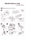
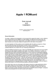
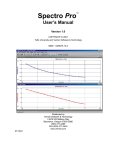
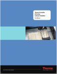
Mesa Laboratories, Inc. Torqo Model 1600 Data Connectivity User Manual Rev A1 (DRAFT) 6‐September‐2013 Page 1 of 17 I. Connectivity Options The Mesa Labs Torqo Model 1600 has several connectivity options to allow data to be sent to a remote computer or network folder. Data can be output from the Torqo Model 1600 using: Serial Port USB Flash memory stick plugged into the Torqo USB Port Ethernet file transfer Ethernet Network Shared Variables Ethernet OPC published variables Ethernet link using Torqo Graph‐It application Some control over the amount and type of data which is sent to the remote computer can be configured in the Torqo System Options menu. The Ethernet shared variable and OPC methods are configured so the remote PC or server computer pulls the data from the Torqo machine. In these cases the data which is archived is selected by the remote computer application which must choose which data items are important, and pull them into the archived storage. Please Note: Implementation of some of these connectivity options requires Torqo Model 1600 operating firmware to be installed with Version 6.0 or later. II. Serial Port The Model 1600 Serial Port can be used to output results data from each test. The Serial Port is a DB‐9 Male connector and can be found on the rear panel of the Model 1600 Tower. The port is labelled "PC OUT" and can be seen in the photograph below. Page 2 of 17 The serial port is set to the following settings by default: 115200 Baud 8 data bits 1 stop bit No parity No handshaking XON/XOFF = Yes The cable that connects the Torqo II+ to the PC should be an RS‐232 cable with the following description. Serial Type, Null Modem, 9 Sub‐D female to 9 Sub‐D female. Mesa Part Number 51.004470 Pin connections are as shown below (RS232 Standard, RS422/485 not used). Page 3 of 17 Configuring the Torqo to send results data out the Serial Port From the Main Menu, select the System Options button. You will see Page 1 as shown below. Press the Auto Transmit to PC button to bring up the Auto Transmit to PC screen. Figure 1 System Options Page 1 Page 4 of 17 Auto Transmit to PC Menu The Auto Transmit to PC Screen allows the user to configure the Torqo Model 1600 to output results data to the Serial Port in ASCII text format at the successful end of each test. This is enabled as shown in the image below. Please note that if Graphit output is enabled the Single Line – End of Test output is disabled automatically. Only one of these output modes may be selected at a time. Figure 2 Auto Transmit to PC Menu with Single Line End of Test Enabled Once the Single Line – End of Test Data mode is enabled, the Configure End of Test Data button becomes visible. Page 5 of 17 Configure End of Test Data Menu The Configure End of Test Data menu allows certain output data to be suppressed from the ASCII data stream if it is not desired. Please note the Units Name and Main Results data are always output at the end of each test in this mode and these cannot be disabled. They are shown greyed out and enabled as a reminder that they will always be output. Figure 3 Configure End of Test Data Menu showing all items Enabled Page 6 of 17 Interpreting Single Line End of Test Data from the Serial Port When transmitting Single Line End of Test results the following data strings are used for the different Test Profile Types. These examples are shown with Configure End of Test Data settings to enable all outputs. If a specific output is disabled, for example Date and Time String the affected ASCII data will not be sent. Please note the <CR><LF> text below are nonprintable ASCII end of line characters. Please note the _ characters represent spaces. Removal Torque Data String Date_Time_Units_Removal Torque_Test Type_Re‐Application Torque<CR><LF> Example: 01/01/00 09:00 lb‐in 10.80 removal 12.00<CR><LF> Example without re‐application torque or test name: 01/01/00 09:00 lb‐in 10.80<CR><LF> Incremental Torque Data String Date_Time_Units_Removal Torque_Test Type_Incremental Torque<CR><LF> Example: 01/01/00 09:00 lb‐in 10.80 inc 12.00<CR><LF> Bridge Torque Data String Date_Time_Units_Removal Torque_Test Type_Bridge Torque<CR><LF> Example: 01/01/00 09:00 lb‐in 10.80 rrt <CR><LF> Reverse Ratchet Torque Data String Date_Time_Units_Torque_Test Type_<CR><LF> Example: 01/01/00 09:00 lb‐in 10.80 rrt<CR><LF> Close Torque Data String Date_Time_Units_Close Torque_Test Type_<CR><LF> Example: 01/01/00 09:00 lb‐in 10.80 close<CR><LF> Strip Torque Data String Date_Time_Units_Strip Torque_Test Type_<CR><LF> Example: 01/01/00 09:00 lb‐in 10.80 close<CR><LF> Page 7 of 17 Testing Single Line End of Test Data from the Serial Port Configure the Torqo Model 1600 as described above. Connect the Serial Cable to the PC on which you will run the test. If your PC does not have a serial port, obtain a USB to Serial adapter similar to the Keyspan USB to Serial Adapter (Mesa PN 300355‐001) and connect the serial cable to the 9‐pin serial port on the PC and the 9‐pin PC OUT port on the Torqo. Run the Hyperterminal serial port emulator application ( which can be downloaded from Hilgraeve ) or a similar serial port terminal emulator. Select the Port number of the serial port to which the cable is connected. Select 115200 baud, 8 bits, 1 stop, no parity, XON/XOFF. This should connect the Hyperterminal to the serial port and it will be waiting for data from the Torqo. On the Torqo insert a bottle into the clamp and press Open. When the test finishes you should be able to observe the result data you have selected on the Hyperterminal screen. Troubleshooting the Serial Port If Hyperterminal is not displaying anything, confirm the COM port number: One way to do this is to bring up the Device Manager; on Windows 7 click Start, right click Computer and click Manage then choose Device Manager and expand the Ports (COM and LPT) selection. While viewing the list of COM ports, unplug the USB to Serial adapter and plug it back in. The COM port for that adapter will be removed from the list and replaced in the list when it is plugged back in. In the image below there are 3 Keyspan USB serial ports (COM1,COM3, and COM4) so unplugging and replugging one will identify it because it will disappear from the list and then reappear. Confirm the type of the serial cable : Using an ohmmeter, verify pin 2 on one end of the cable connects to pin 3 on the other end of the cable. Confirm the serial cable is connected to the PC OUT port on the Torqo and confirm Single Line End Of Test Data is Enabled on the Torqo. If it displays garbled characters check the baud rate; the baud rate is 115,200 by default on the Model 1600. The baud rate is 9600 by default on the Model 1590. Confirm the Handshaking setting is Xon/Xoff or None. Page 8 of 17 III. USB Flash Memory Stick Data may be exported to a file on a USB Flash drive plugged into the USB connector on the Torqo touchpanel – the connector is under the bottom of the touchpanel enclosure and it has a threaded watertight cover on it. Unscrew the cover and plug in the USB Flash Drive. Wait about 30‐40 seconds for the Windows Embedded operating system to recognize the Flash drive has been added. Configure the Torqo to send data to the USB Flash drive by selecting System Options from the Main Menu and pressing Next Page until Page 3 is reached. You will see the Export Format button and the Export Options button as shown below. Figure 4 System Options Page 3 Showing Export Format and Export Options Buttons The Export Format button cycles thru the selections for the export data format. The selections are: Excel (actually tab separated values are used). CSV (comma separated values). Text (this is the same report as appears in the View/Print screen). XML (this is the native Torqo XML schema containing all the data, test profile and conditions of the test) ‐ a copy of the native Torqo data file. The Export Options button brings up the following Export Options screen where the destination of the Export is selected to be the USB Flash drive or a network shared folder. For USB data export select Export Destination to be USB Flash Drive as shown. Page 9 of 17 Export Waveform Data is disabled and greyed out, this is a future feature. Export All Details can be enabled or disabled. Export All Details disabled will export the test results. Export All Details Enabled will also export pass fail conditions of the test. Figure 5 Export Options button showing USB Flash Drive as the destination. Exporting Data from a test run: Once you have opened a set of bottles, press the View/Print button to review the results data. Page 10 of 17 Figure 6 General screen showing View/Print button The View/Print Report screen is shown, an example is below. If data has been collected the Export button is enabled. Pressing the Export button will export the data to the USB memory stick in the selected format. Figure 7 View/Print Report with Data showing Export button Page 11 of 17 The filename is the name of the profile with a date and time stamp appended to the name. A screen will appear confirming the file transfer was completed and giving the new filename on the USB stick. If the file transfer could not be completed – the USB stick was not plugged in or could not be written to or was full – an error will be displayed. Figure 8 Confirmation screen for USB File Export Troubleshooting the Flash Drive Confirm that the Flash Drive is plugged into the Torqo USB socket: There are two USB sockets, one underneath the touchpanel enclosure, typically used for the Flash Drive, and one on the rear of the unit, typically used for the USB printer option. The USB ports are identical and either one may be used for the Flash Drive. Confirm that the Flash Drive works and has free space available on it : Plug the Flash Drive into a Windows PC and verify it can be read and is not full. Wait for 30‐40 seconds after plugging the Flash Drive into the Torqo: The Windows operating system takes a short time to recognize the Flash Drive is plugged in and to make it available to the Torqo application. Confirm that the Export Options are set to USB Flash Drive. Confirm that the Export Format is set to the desired file format. Confirm that there are data samples visible in View/Print. The Export Data button is disabled and greyed out if there are no samples. Page 12 of 17 IV. Ethernet File Transfer Exporting data to a file located on an Ethernet connected drive is similar to the USB file export; please refer to that section for more details. The Export Destination in the Export Options menu in System Options Page 3 is set to Network Folder as shown below. Figure 9 Export Destination set to Network Folder When the Select Export Folder button is clicked, a folder browser appears to allow you to browse the network to locate the desired destination folder. Select Network on the left side then select the network location and the folder and then click Current Folder. Page 13 of 17 There are a few requirements to being able to select a network folder for export; your local IT department can help satisfy these requirements: The network drive, target computer, and folder must be able to be seen in the file browser. The selected network folder is tested to make sure the Torqo can write to the folder – the Torqo touchpanel PC must have write permissions to the selected folder. It is possible that network permissions will need to be created by creating a user on the Torqo touchpanel and having users log in to the Torqo touchpanel at the start of their shift; This will depend on your local IT requirements for the plant and network. See the Network Security section below or contact Mesa Labs for more information if this is required. When a network folder location is seected, the Torqo attempts to create and then delete a test file in the selected network folder. If the network folder cannot be written to an error message will appear telling you that the location may not be used. V. Ethernet Link to Torqo Graph‐It Application When the Torqo is used in a laboratory setting or detailed torque studies are desired to be run using the machine, the torque waveform data as well as the torque results may be sent to a PC in another location using an Ethernet link. The target PC will run the Torqo Graph‐It Windows application which will harvest the waveform and results data and store them to an Excel file. There are three steps to setting this up: Connect the Torqo instrument to the Ethernet; Set up the Torqo instrument to output data to Graph‐It over the Ethernet; Set up the PC to run the Torqo Graph‐It Windows application to harvest the data. Step 1: Connect the Torqo instrument to the Ethernet. Using an Ethernet cable, connect the LAN connector on the rear of the Torqo tower to an Ethernet connection in the plant. The LAN connector has a watertight cover that must be removed before a connection is made. The Ethernet connection can be any Ethernet local area network, network router, network switch, network hub or a PC running, for example, Windows 7. The network connection must run DHCP and must issue a network address to the Torqo instrument touchpanel PC when it is connected. Your local IT support must be able to grant network access to the Torqo touchpanel PC. See the Network Security section below for more details. The Torqo instrument's touchpanel PC must be routable from the PC running the Torqo Graph‐It Application. That means there is not a firewall, subnetwork or other security measures which keep the PC from 'seeing' the Torqo instrument. If the PC can 'ping' the Torqo instrument successfully or see it on a list of named computers on the network then it is routable. Step 2: Set up the Torqo instrument to output data to Graph‐It over the Ethernet. From the Main Menu select System Options. On Page 1 of System Options as shown below, press the Auto Transmit to PC button to get the Auto Transmit to PC Menu. Page 14 of 17 Figure 10 System Options Page 1 Showing Auto Transmit to PC Button. In the Auto Transmit to PC menu set the Graphit button to Enabled. Note this will disable Single Line – End of Test data. Select the Graphit Interface to be Ethernet. The current IP Address of the Torqo instrument will be displayed as My IP Address. Note you may need to press OK then go back into the Auto Transmit to PC menu after selecting Ethernet mode to refresh My IP Address in the display. Figure 11 Auto Transmit to PC Menu showing Graphit set to Ethernet mode. Step 3: Run the Torqo Graph‐It application to harvest the data from the Torqo instrument. Page 15 of 17 On the PC also connected to the Ethernet and routable to the Torqo instrument, run the Torqo Graphit application. Select Options, Com Ports as shown below. Figure 12 Torqo Graphit application showing the Options Com Ports menu selection. Select the Ethernet radio button. You can then type in the My IP Address that was shown on the Torqo Instrument in the Auto Transmit to PC menu. Make sure you type in the numbers exactly. Alternately you can Search for Torqo machines on the network. Torqo machines are recognized by having computer names TORQO2M‐YY‐XXXX where YY‐XXXX is the serial number of the individual machines. Figure 13 Ethernet interface mode showing Torqo Network Address and Search for Torqo buttons. Page 16 of 17 Please note some IT departments will require the default factory Torqo Instrument computer names to be changed for security. If there is a specific name or base naming convention used at your plant, these can be used in the Search for Torqo function but they may no longer conform to the Mesa naming convention TORQO2M‐YY‐XXXX. If you want to 'Ping' the Torqo instrument from the PC to see if the network address is routable, note My IP Address from the Torqo instrument. Our example is 192.168.254.203. Open a Command window on the PC which will run Torqo Graphit. Type the command 'ping' followed by the My IP Address with dot separators: Ping 192.168.254.203 The command will attempt to ping to the Torqo instrument and will either succeed or fail with some failure diagnostic text. Make sure you typed the IP address correctly as it's easy to make a mistake here. You might try to recheck the My IP Address on the instrument to make sure the whole setup was plugged in and running when the IP address was issued. VI. Ethernet Network Shared Variables and OPC published variables VII. Network Security Page 17 of 17