1
VoIP Orderwire Version 2
USER MANUAL
Visit our website at www.dpstelecom.com for the latest PDF manual and FAQs.
August 17, 2015
D-UM-216OW
Firmware Version 1.0A
Revision History
August 17, 2015
Initial Release
This document contains proprietary information which is protected by copyright. All rights are reserved. No part of this
document may be photocopied without prior written consent of DPS Telecom.
All software and manuals are copyrighted by DPS Telecom. Said software and manuals may not be reproduced, copied,
transmitted or used to make a derivative work, by either mechanical, electronic or any other means in whole or in part, without
prior written consent from DPS Telecom, except as required by United States copyright laws.
© 2010 DPS Telecom
Notice
The material in this manual is for information purposes and is subject to change without notice. DPS Telecom shall not be
liable for errors contained herein or consequential damages in connection with the furnishing, performance, or use of this
manual.
Contents
Visit our w ebsite at w w w .dpstelecom .com for the latest PDF m anual and FAQs
1 VoIP Orderwire Overview
1
2 Specifications
2
3 Shipping List
3
4 Optional Accessories
4
5 Build Options
4
6 Installation
5
6.1 Tools Needed
5
6.2 Mounting
6
6.3 External Speaker
6
7 VoIP Orderwire Back Panel
7
7.1 Single Amphenol Build Option
7
7.2 Dual Amphenol Build Option
8
7.3 Power Connection (-48 or -24VDC Build Option)
9
7.3.1
Line Connection
10
7.4 LAN Connection
11
7.5 Optional 10/100 Switch
11
7.6 RTU Build Only
12
7.6.1
50-Pin Alarm and Control Relay Connector
12
7.6.2
Discrete Alarms
12
7.6.3
Analogs
13
7.6.3.1
Switching Analog Alarms to Current Operation
8 VoIP Orderwire Front Panel
8.1 Craft Port
9 Quick Start: How to Give the Orderwire an IP Address
13
14
14
15
9.1 ...via Craft Port (using TTY interface)
18
9.2 ...via LAN
18
10 TTY Interface
19
10.1 Change Ethernet Settings
19
10.2 View Directory
20
10.3 View Hardware Config & Stats
20
11 Three Modes of Operation
21
11.1 Direct Station-to-Station Calling (Option #1)
21
11.2 Hoot 'n Holler (Option #2)
21
11.3 Bridge Party Line (Option #3)
22
12 Web Browser
12.1 Logging on to the VoIP Orderwire
23
23
12.2 Changing the Default Password
24
12.3 System Settings
25
12.3.1
Offnet Settings
27
12.4 Ethernet Settings
28
12.5 Notifications
29
12.5.1
SNMP Notification
29
12.5.2
Relay Notification
30
12.5.3
Schedule
30
12.6 Alarms
31
12.7 Systerm Alarms
32
12.8 Controls
33
12.9 Analogs
34
12.9.1
Basic Configuration
34
12.9.2
Detailed Configuration
35
13 How to: Setup Directory Listings
36
14 How To: Navigate the Voice Menus
38
15 How To: Talk to Third-Party SIP Devices
38
16 How To: Upgrade Firmware
39
17 Front and Back Panel LEDs
40
18 Reference Section
41
18.1 Display Mapping
41
18.2 System Alarms Display Map
42
18.3 SNMP Manager Functions
44
18.4 SNMP Granular Trap Packets
45
19 Technical Support
46
20 End User License Agreement
49
1
1
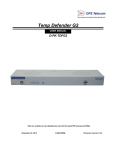
VoIP Orderwire Overview
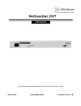
Fig. 1.1 VoIP Orderwire delivers fast, convenient communication between sites.
This next-gen orderwire product from DPS Telecom delivers voice communication at all your LAN sites.
Using VoIP (Voice over IP) technology, you call another orderwire station, a select group of stations, or
use the Hoot ‘n Holler “all call” feature to page someone when you’re not sure where they are.
Minimum Bandwidth Requirement: 128Kbps for peer to peer calls, or at least two DS0's in a
fractional T1 WAN.
Plus, in the same chassis, you have the option of also getting an RTU with 16 discrete alarm inputs, 8
analog inputs, and 2 control relays. Each VoIP OrderWire unit installs easily - just plug into your LAN
hub. In just 1 RU of space, you can get rid of all those costly telephone lines and long-distance fees.
VoIP communication uses the industry-standard SIP 2.0 protocol and G.711 codec, making this
orderwire system even easier to work with if you’re already familiar with VoIP.
2
2
Specifications
Dimensions:
1.72" H x 17.0" W x 6.64" D
Weight:
2.6 lbs
Mounting:
19" or 23" rack or wall mount
Protocol:
SIP 2.0, RTP
Voice Codec:
G.711 Mu-Law
Power Input:
Dual -48 VDC, +24 VDC, or -24 VDC (build options)
Current Draw:
300mA
Fuse:
Dual 3/4 Amp GMT Fuses recommended
Interfaces:
1 RJ45 10/100BaseT Ethernet port
Visual Interface:
1 DB9 craft port, 9600 Baud serial
1 RJ-11 Telco jack (optional)
1 or 2 50-pin Amphenol connectors (RTU-builds only)
1 2-Wire handset jack *
1 External speaker jack *
(Optional) 4 Port 10/100BaseT Switch
5 or 6 Front Panel LED
5 Back Panel LEDs
Operating Temperature:
32°–140° F (0°–60° C)
Operating Humidity:
0%–95% non-condensing
RoHS:
5/6
Handset:
Standard 2-Wire telephone (optional)
External Speaker:
Yes (optional)
* These jacks can be located on the front or the back of the unit, specified when you order.
RTU Build Only:
Alarm Termination: Via 50-pin Amphenol connector on back panel
Discrete alarms:
16
Analogs:
8
Controls:
2 or 18
This unit does not contain any operator-serviceable parts.
All servicing is to be performed by DPS Telecom only.
3
3
Shipping List
Please make sure all of the following items are included with your VoIP Orderwire. If parts are missing,
or if you ever need to order new parts, please refer to the part numbers listed and call DPS Telecom at
1-800-622-3314.
VoIP Orderwire
D-PK-216OW
VoIP Orderwire User Manual
D-UM-216OW
VoIP OrderWire Resource CD
(Includes Manual, MIBs, & Firmware)
14 ft. Ethernet Cable
D-PR-923-10A-14
6 ft. DB9M-DB9F Download Cable
D-PR-045-10A-04
2-Pin Connector
2-820-00862-02
x2
x2
19" Rack Ears
D-CS-325-10A-00
x2
Two Standard Rack Screws
1-000-12500-06
x2
23" Rack Ears
D-CS-325-10A-01
x4
Four 3/8" Ear Screws
1-000-60375-05
x2
Two Metric Rack Screws
2-000-80750-03
Pads
2-015-00030-00
4
x4
3/4 Amp Fuses
2-741-00750-00
2-Wire Telephone (Optional)
D-PR-675-10A-00
External Speaker (Optional)
pair wire
FDO-1200-10A-00
Small 2-Pin Connector and 6ft of 2
4
(for plugging in External Speaker)
2-820-00812-02
Optional Accessories
Pluggable Back Panel
D-PK-16PAN
The VoIP OrderWire's pluggable back panel allows for screw-in barrier plug connections for the
NetGuardian's alarms and control relays. (The Pluggable Back Panel is only for RTU models of
the OrderWire.)
5
Build Options
The VoIP OrderWire has the option to be ordered with single or dual Amphenol connectors for adding
alarm monitoring capability.
Single Amphenol RTU build option:16 Discrete alarms, 8 Analogs, 2 Control Relays
Dual Amphenol RTU build option: 16 Discrete alarms, 8 Analogs, 18 Control Relays
5
6
6.1
Installation
Tools Needed
To install the VoIP Orderwire, you'll need the following tools:
Phillips No. 2 Screwdriver
PC with terminal emulator,
such as HyperTerminal
Small Standard No. 2 Screwdriver
6
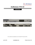
6.2
Mounting
Flush mount - Rack ears are installed @ front of the unit, with front panel flush to the rack
Rack mount - Rack ears are installed @ back of the unit
Fig. 4.1 The VoIP Orderwire can be flush or rear-mounted
The Orderwire mounts in a 19" or 23" rack, and can be mounted on the right or left, in the flush-mount
or rear mount locations.
Fig. 4.2
Fig. 4.3
6.3
External Speaker
Fig. 4.4 - Connecting the external speak er.
7
7
VoIP Orderwire Back Panel
7.1
Single Amphenol Build Option
VoIP Orderwire back panel connections. NOTE: 50-pin Amphenol connector is only on the RTUversions of the VoIP Orderwire.
8
7.2
Dual Amphenol Build Option
VoIP Orderwire back panel connections. NOTE: 50-pin Amphenol connectors are only on the RTUversions of the VoIP Orderwire.
9
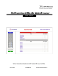
7.3
Power Connection (-48 or -24VDC Build Option)
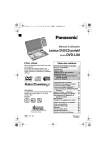
VoIP Orderwire is powered by two screw terminal barrier plug power connectors.
Fig. 5.2 Screw terminal barrier plugs
To connect the VoIP Orderwire to a power supply, follow these steps:
1. Always use safe power practices when making power connections. Be sure to remove fuses from
the fuse distribution panel, as well as the back of the VoIP Orderwire, before making your power
connections.
2. Use the grounding lug to connect the unit to earth ground. The grounding lug is next to the
symbol. Insert the eyelet of the earth ground cable between the two bolts on the grounding lug
(Ground cable not included).
3. Insert a battery ground into the power connector plug's right terminal and tighten the screw; then
insert a battery line to the plug's left terminal and tighten its screw.
4. Insert a fuse into the fuse distribution panel and measure voltage. The voltmeter should read between
–40 and –70VDC (for -48VDC build option) or -18 and -36VDC (-24VDC build option).
5. The power plug can be inserted into the power connector only one way to ensure the correct polarity.
Note that the negative voltage terminal is on the left and the GND terminal is on the right.
6. Insert fuse into the Power A fuse slot. The power LED should be lit green. If the LED is red, the power
connection is reversed. To confirm that power is correctly connected, the front panel LEDs will flash
RED and GREEN, indicating that the firmware is booting up.
7. Repeat steps 1 -6 for Power B connector.
10
7.3.1
Line Connection
Your VoIP Orderwire unit may include a line connection on the back panel. The line connection provides
for Offnet capability, which allows a person can access the Orderwire system via POTS (Plain Old
Telephone Service.)
Note: The Orderwire's Offnet feature is not available with alarming features.
11
7.4
LAN Connection
To connect the VoIP Orderwire to LAN, insert a standard RJ45 Ethernet cable into the 10/100BaseT
Ethernet port on the back of the unit. (See Fig. 5.1) If the LAN connection is OK, the LNK LED will light
SOLID GREEN.
7.5
Optional 10/100 Switch
The VoIP Orderwire 10/100BaseT switch option extends LAN access at your site
The VoIP OrderWire can be built with a 10/100 switch replacing the unit's standard ethernet port,
allowing you to extend LAN access at your site without installing a separate switch.
Note: The VoIP Orderwire operates at 10BaseT. The switch offers 10/100BaseT speeds to other
devices connected to the switch.
To power and activate the integrated ethernet switch, insert a 1/2 amp GMT fuse in the switch's
fuse socket.
RJ45 Ethernet Connection
8
7
6
5
4
3
2
1
Trasm it Out – (TO–)
Trans mit Out + (TO+)
Receive In – (RI–)
Receive In + (RI+)
Fig. 6.8.2. Regular Ethernet port pinout
LED
1-4
LNK
LAN
Status
Description
Blink Green
Activity over indicated integrated Ethernet Switch port
Solid Green
Link detected
Solid Green
Switch is active
Off
Solid Green
Switch malfunction or switch top board not powered
LAN activity detected at RTU
Back panel LED Status message descriptions
12
7.6
RTU Build Only
7.6.1
50-Pin Alarm and Control Relay Connector
The primary connector for discrete alarms, analog alarms and control relays is the 50-pin connector on
the VoIP Orderwire's back panel.
7.6.2
Discrete Alarms
Dry Contact
Contact to Ground
NetGuardian case
– Batt.
NetGuardian case
GND
GND
Alarm
Alarm
– Batt.
Note: Make sure that grounds have a common reference this is usually done by tying grounds together.
Fig. 5.3 Discrete alarm points can connect as a dry contact or a contact to ground
The VoIP Orderwire features 16 discrete alarm inputs - also called digital inputs or contact closures.
Discrete alarms are either active or inactive, so they're typically used to monitor on/off conditions like
power outages, equipment failures, door alarms and so on. The NetGuardian's discrete alarm points
are single-lead signals referenced to ground. The ground side of each alarm point is internally wired to
ground, so alarm points can connect either as a dry contact or a contact to ground.
In a dry contact alarm: The alarm lead brings a contact to the ground lead, activating the alarm.
In a contact to ground alarm: A single wire brings a contact to an external ground, activating the
alarm.
You can reverse the polarity of each individual discrete alarm point, so that the alarm is activated when
the contact is open. This is done with a software configuration change.
13
7.6.3
Analogs
The VoIP Orderwire's 8 analog alarm inputs measure continuous ranges of voltage or current. Analog
alarms are typically used to monitor battery voltage, charging current, temperature, humidity, wind
speed, or other continuously changing conditions. The measurement range of the analog channels is –
90 to +90 VDC or 4 to 20 mA. To configure the analogs for current sensing (4 - 20mA) please review
the next section for jumper position.
You can use analogs 1 through 4 to monitor whatever you like. Analogs 5 through 8 are pre-configured
to monitor Battery A and B, Internal Temperature, and External Temperature. Read the following table to
see where to connect the analogs.
Analog #
ANA 1
ANA 2
ANA 3
ANA 4
ANA 5
ANA 6
ANA 7
ANA 8
7.6.3.1
Connection
User-definable; connects to the 50-pin amphenol.
User-definable; connects to the 50-pin amphenol.
User-definable; connects to the 50-pin amphenol.
User-definable; connects to the 50-pin amphenol.
Pre-configured to monitor Battery A.
Pre-configured to monitor Battery B.
Pre-configured to monitor Internal Temperature. Located in the
center or edge of PCB.
Pre-configured to monitor External Temperature via jack to
external temperature probe.
Switching Analog Alarms to Current Operation
Fig. 5.4. Adjustable jumpers on the VoIP Orderwire circuit board
By default, the analog inputs are configured to measure voltage. You can switch the analog inputs
to measure current by resetting jumpers on the VoIP Orderwire's circuit board.
To test the analog alarm voltage/current jumpers, follow these steps:
1. Make sure the VoIP Orderwire is depowered and disconnected from all network connections.
2. Remove the screws from the sides of the VoIP Orderwire case.
3. Slide the top cover of the case off to expose the circuit board.
14
4. The adjustable jumpers are shown above. All alarm inputs can be individually configured for
current or voltage operation. Remember that the default jumper position is OPEN for measuring
voltage. Note: Each jumper inserts a 250-ohm shunt resistor across the input. This must be
taken into account when defining the analog input reference scale.
Jumper installed for current
Current
+
250 Ohm
Shunt
-
4 to 20 mA
Current Source
Transducer
Analog
Channel
Input
Jumper removed for voltag e
Voltage
+
Voltage Source
Transducer
Analog
Channel
Input
Unjumpered/Open Position:
Voltage Operation (default)
Jumpered/Closed Position:
Current Operation
Jumper
J20
J21
J22
J23
Analog
ANA 1
ANA 2
ANA 3
ANA 4
-
Fig. 5.6. Jumper settings for analog alarms inputs.
5. Slide the top cover of the case back into position and replace the screws.
6. Reconnect and power up the VoIP Orderwire.
8
VoIP Orderwire Front Panel
Fig. 6.1. The VoIP Orderwire's front panel connections
8.1
Craft Port
Use the front panel craft port to connect the VoIP Orderwire to a PC for onsite unit configuration. To use
the craft port, connect the included DB9 download cable from your PC's COM port to the craft port.
Pinout is shown in Fig. 6.1 for reference, but you will most likely be using a straight-through cable.
15
9
Quick Start: How to Give the Orderwire an IP Address
1. In this step, we'll use create a physical cable connection between your PC's COM port and the
unit's craft port. Note: You must be connected via craft port or Telnet to use the TTY interface.
Make sure you are using the straight through (1 to 1) Male to Female DB9-DB9 download cable
provided with your VoIP Orderwire to make a craft port connection.
Fig. 7.1 Connection through front Craft Port
To access HyperTerminal using Windows:
2. Click on the Start menu > select Programs > Accessories > Communications >
HyperTerminal.
Fig. 7.2 How to access HyperTerminal.
16
3. At the Connection Description screen, enter a
name for this connection. You may also select an
icon. The name and icon do not affect your ability
to connect to the unit.
4. At the Connect To screen, select COM1
(most commonly used) from the drop down and
click OK.
Fig. 7.3
Fig. 7.4
5. Select the following COM port options:
• Connect using COM1 or appropriate COM
port
• Bits per second: 9600
• Data bits: 8
• Parity: None
• Stop bits: 1
• Flow control: None
Once connected, you will see a blank, white
HyperTerminal screen. Press Enter to activate
the configuration menu.
6. When prompted, enter the default user
name admin and password dpstelecom.
NOTE: If you don't receive a prompt for your
user name and password, check the port you
are using on your PC and make sure you are
using the cable provided.
Fig. 7.6
Fig. 7.5
17
7. The Orderwire's main main menu will appear. 8. ESC to the main menu. When asked if you'd
Type C for C)onfig, then E for E)thernet. Configure like to save your changes, type Y for Y)es.
the unit's IP address, subnet mask, and default
Reboot the unit to save its IP Address.
gateway.
When this is complete, you are ready to assign
your station a Station ID number.
See section "How To: Navigate the Voice
Menus" to accomplish this via the handset
or....
See section "How To: Setup Directory
Listings" to perform this task via the web
interface.
Fig. 7.7
18
9.1
...via Craft Port (using TTY interface)
The TTY interface is the VoIP Orderwire's built-in interface for basic configuration. You can configure
unit's Ethernet port settings and view debug. For more advanced configuration tools, please use the
Web Browser Interface.
For Telnet, connect to the IP address at port 2002 to access the configuration menus after initial LAN/
WAN setup. Telnet sessions are established at port 2002, not the standard Telnet port as an
added security measure.
Menu Shortcut Keys
The letters before or enclosed in parentheses () are menu shortcut keys. Press the shortcut key to
access that option. Pressing the ESC key will always bring you back to the previous level. Entries are
not case sensitive.
9.2
...via LAN
Fig. 7.8 - Connection through Ethernet port
To connect to the Orderwire via LAN, all you need is the unit's IP address (Default IP address
is 192.168.1.100).
If you DON'T have LAN, but DO have physical access to the VoIP Orderwire, connect using a
LAN crossover cable. NOTE: Newer PCs should be able to use a standard straight-through LAN cable
and handle the crossover for you. To do this, you will temporarily change your PC's IP address and
subnet mask to match the Orderwire's factory-default IP settings. Follow these steps:
1. Get a LAN crossover cable (not included) and plug it directly into the VoIP Orderwire's LAN
port.
2. Look up your PC's current IP address and subnet mask, and write this information down.
3. Reset your PC's IP address to 192.168.1.200.
4. Reset your PC's subnet mask to 255.255.192.0. You may have to reboot your PC to apply your
changes.
5. Once the IP address and subnet mask of your computer coincide with the unit, you can access
the Orderwire via a Telnet session or via Web browser by using the unit's default IP address of
192.168.1.100.
6. Provision the unit with the appropriate information, then change your computer's IP address and
subnet mask back to their original settings
19
10 TTY Interface
The TTY interface is the built-in interface for basic configuration. From the TTY interface, you can:
Edit the IPA, subnet, and gateway
Debug and troubleshoot
View hardware config
Set unit back to factory defaults
For more advanced configuration tools, please use the Web Browser Interface.
For Telnet, connect to the IP address at port 2002 to access the configuration menus after initial LAN/
WAN setup. Telnet sessions are established at port 2002, not the standard Telnet port as an
added security measure.
Menu Shortcut Keys
The letters before or enclosed in parentheses () are menu shortcut keys. Press the shortcut key to
access that option. Pressing the ESC key will always bring you back to the previous level. Entries are
not case sensitive.
10.1
Change Ethernet Settings
Fig. 8.1 - View and edit network settings.
1. Login to the TTY interface, then press C)onfig > E)thernet.
2. From this screen, you have the option to edit the IPA, Subnet, Gateway, DHCP, and Host Name.
20
10.2
View Directory
The Directory serves as your internal "phonebook", used when calling other Orderwire stations in your
network.
Fig. 8.2 - See your list of other orderwire stations on the network.
1. Login to the TTY interface, then press C)onfig > D)irectory.
2. You will see the Station IDs currently setup in your orderwire system. The TTY interface will display
the ID, Station Number, IP address, and Location.
10.3
View Hardware Config & Stats
Fig. 8.3 - Confirm the build options of your Remote Power Switch.
1. Login to the TTY interface, then press C)onfig > S)tats.
2. You will see the hardware options available on your VoIP Orderwire unit, as well as the firmware
version, uptime, etc.
21
11 Three Modes of Operation
11.1
Direct Station-to-Station Calling (Option #1)
How It Works
User picks up the handset and dials another orderwire station directly by dialing the 4-digit "Station ID".
The station will “ring” until the party has answered by picking up the handset. This call is considered
private because other stations will not be able to hear the conversation. If you receive a call while in a
private conversation you will hear a beep. Hang up, and wait for the handset to ring to pick up.
Fig. 9.1. Station-to-station calling topology.
11.2
Hoot 'n Holler (Option #2)
How It Works
Hoot 'n Holler is a non-private form of communication. This “all call” type feature allows you to speak to
every Orderwire station in the same subnet. Personnel will hear your voice through the speaker at each
station - Great if you’re trying to locate someone or page all your staff. To join the call, simply pick up the
telephone. The conversation is heard by other stations not on the call. If another orderwire station
picks up the hand set, a private call will be initiated.
NOTE: Hoot 'n Holler mode only works on stations within the same IP subnet. This mode requires more
bandwidth on the subnet for which this station is assigned. (UDP traffic)
22
Fig. 9.3. Hoot 'n Holler mode topology.
11.3
Bridge Party Line (Option #3)
How It Works
This mode is similar to Hoot 'n Holler in that up to 5 stations may be joined in a conversation. Multiple
stations join a private call where parties dial into a conference bridge to talk at the same time. This
allows you to privately conference with two or more Orderwire stations across the network. For added
security and privacy, the bridge will give an audible indication when another station joins or exits the
call.
To access a conference bridge, dial 3 then the ID of the conference bridge.
NOTE: Bridge Party Line mode only works with a VoIP Bridge Server (D-PK-216ow-12008)
Fig. 9.4. Bridge party line (conference) topology.
23
12 Web Browser
The VoIP Orderwire unit features a built-in Web Browser Interface that allows you to configure the unit
through the Internet / Intranet. You can quickly change the sign-in password, setup your Directory
Listings, and reboot the unit using the most commonly used browsers.
NOTE: Max # of users allowed to simultaneously access the VoIP Orderwire via the Web is 2.
12.1
Logging on to the VoIP Orderwire
For Web Interface functionality, the unit must first be configured with some basic network information. If
this step has not been done, refer to the section "Quick Start: How to Give the Orderwire an IPA" for
instructions on initial configuration setup.
1. To connect to the Orderwire from your Web browser, enter its IP address in the address bar of your
web browser. It may be helpful to bookmark the logon page to avoid entering this each time.
2. After connecting to the unit's IP address, enter your login information and click OK. NOTE: The
factory default username is "admin" and the password is "dpstelecom".
Fig. 10.1. Enter your password to enter the Web Browser Interface
24
12.2
Changing the Default Password
The password can be configured from the Edit > System screen. The minimum password length is
four characters; however, DPS recommends setting the minimum password length to at least five
characters.
Use the following steps to change the logon password:
1. From the Edit menu select System.
2. Enter the new user name in the User field.
3. Enter the new password in the Password field.
4. Click the Save button.
Fig. 10.2 - Global System Settings section of the Edit > System menu
NOTE: You will see the following popup when making changes to the VoIP Orderwire from the Edit
menu. It will appear when confirming your changes to the database, either by clicking Next in the setup
wizards or the Save button.
Fig. 10.3 - Commit to NVRAM popup
25
12.3
System Settings
Name
Location
Contact
SNMP Get String
SNMP Set String
User
Fig. 10.4
Global System Settings
Enter a name to help you identify this VoIP Orderwire
station.
Enter the location of this VoIP Orderwire station. This field
will be reported to other stations during the Auto-Discovery
process.
Enter the contact phone number for the person responsible
for this unit.
Community name for SNMP requests. {case-sensitive).
Community name for SNMP SET requests. (casesensitive).
The logon user name used to access this unit via the web
or TTY interface. Default is "admin"
26
Password
English/Russian
Voice Over Serial
DCP Unit ID/Protocol
DCP over LAN port/protocol
DCP over Serial
Disable/Enable
Enable Alarm Echo over
Serial
Remote Unit IP / LAN Port /
Protocol
Remote DCP Unit ID /
Protocol
Poll delay
Timeout
Initialize Configuration
Backup Configuration
Restore Configuration
The logon password used to access this unit via the web or
TTY interface. Default is "dpstelecom"
Global Call Settings
Sets the Language for the Orderwire's Voice Prompts
Using G.726 encoding, sends voice over back serial port.
Note: Works with DVF64 G2 Device.
DCP Responder Settings
Set the address identifying this Orderwire unit to T/Mon
Set the DCP Port address.
Listens to DCP requests over back serial port. If Voice over
Serial enabled, DCP over Serial can still be used.
Alarm Echo Settings
Enable or Disable the Alarm Echo feature. You need two
separate RTUs in order to use Alarm Echoes.
Sends DCP requests over back serial port. If voice over
serial enabled, this feature can still be used.
Enter the IP Address of the target unit. You can find this IP
in the ethernet settings of the target device. The LAN Port
will specify the communication line that will be used to talk
to the unit. The Protocol will define the format that data will
be sent and received. The LAN Port should match the DCP
Unit's LAN Port located in the DCP Responder section
above. The Protocol should match the device you are
polling.
Enter the DCP Unit ID of the device you want to monitor.
This should match the DCP Unit ID located in the DCP
Responder section above. The Protocol will define the
format that data will be sent and received.
How often the Orderwire will poll the DCP Responder unit.
The poll delay is the interval of time between polls.
How long the Orderwire will wait to receive a response
before it times out. If the Orderwire is unable to
communicate with the responder unit, and times out three
times in a row, a system alarm will become enabled.
System Controls
Sets the unit's configuration back to all factory defaults.
NOTE: Initializing the Orderwire's config means the
Directory listings will have to be entered again.
Used to backup (save) the current configuration to your PC
or on the network.
Allows you to browse for a saved configuration file on your
PC or on the network.
27
12.3.1 Offnet Settings
Certain Global Call Settings are only available on Orderwire units equipped with the Offnet option.
Setting
English/Russian
Description
The language of the voice prompts given when using the Orderwire
This setting sets the number of rings before the Orderwire will go off hook
Number of Rings (PTSN)
and play menu options.
This setting indicates the number of rings before the Orderwire will forward
Number of Rings (VOIP)
VoIP incoming calls
Set the country of operation for your phone system. This setting adjusts
Country
the Orderwire's POTS settings for compliance with your country's
standards
The frequency of the disconnect tone. If the disconnect tone for your PBX
Disconnect Tone (Hz) network consists of a single frequency, insert the same value for both
frequencies 1 and 2. (Default value is 420 for both frequencies 1 and 2.)
The disconnect threshold is the number of times the Orderwire must
detect a disconnect tone in a 10 second period to go on hook. If having
Disconnect Threshold trouble with frequent disconnects, increase this value. If the line is
remaining off hook too long after calls, decrease this value. (Default value
is 15.)
The number of seconds before the Orderwire will begin detecting a
Disconnect Tone. This setting can be helpful on those networks where the
Disconnect Timeout
dial tone and disconnect tones are identical, preventing the Orderwire from
hanging up on users initiating calls through the Orderwire.
28
12.4
Ethernet Settings
Fig. 10.5 - Edit > Ethernet menu.
MAC Address
Enable VLAN
VLAN ID
PCP
Unit IP
Gateway
Subnet Mask
DNS Server 1
DNS Server 2
Ethernet Settings
Hardware address of the VoIP Orderwire. (Not editable - For
reference only.)
Used to turn on Virtual LAN. Uncheck to disable VLAN.
Used to turn on Virtual LAN. Uncheck to disable VLAN.
PCP is the Priority Code Point. Values listed in parentheses are the
priority for each class; 0 represents the lowest priority, 7 is the
highest. VLAN PCP is placed on 2 by default.
IP address of the VoIP Orderwire station. This field will be reported to
other stations during the Auto-Discovery process.
An important parameter if you are connected to a wide-area network.
It tells the unit which machine is the gateway out of your local network.
Set to 255.255.255.255 if not using.
A road sign to the VoIP Orderwire, telling it whether your packets
should stay on your local network or be forwarded somewhere else
on a wide-area network.
Primary IP address of the domain name server. Set to
255.255.255.255 if not using. Not currently used by this application
- Designed for future use.
Secondary IP address of the domain name server. Set to
255.255.255.255 if not using. Not currently used by this
application - Designed for future use.
29
12.5
Notifications
From the initial Edit > Notifications menu, you will see which of the 8 notifications are enabled, their
server, and schedule. Click on the number link for one of the notifications to begin configuration.
Fig. 10.6 - The Edit > Notifications menu
Once you've chosen which notification you want to setup, check the Enable Notification to turn it "on."
Then choose a notification method, either email or SNMP.
12.5.1 SNMP Notification
SNMP Notification Fields
SNMP Trap Server IP
Trap Port No.
Trap Community
SNMP Trap Version
SNMP Notification
The SNMP trap manager's IP address.
The SNMP port (UDP port) set by the SNMP trap manager to
receive traps, usually set to 162.
Community name for SNMP TRAP requests.
Choose between SNMP v1 or v2c
30
12.5.2 Relay Notification
Relay Notification
Relay Number
Relay Notification
Relay to be latched when any alarm assigned to this notification
is set.
12.5.3 Schedule
The Edit > Schedule menu is where you will tell the VoIP Orderwire exactly which days and times you
want to receive alarm notifications. You set 2 different schedules for each discrete base alarm.
Fig. 10.8 - The Schedule creation screen
Days of the week
Any Time
Notification Time
Notification Scheduling
From either Schedule 1 or 2, check which days you want to receive
notifications.
Select to tell the VoIP Orderwire you want to receive alarm notifications at
any time for the day(s) you've selected.
Used to tell the NetGuardian to only send alarm notifications during
certain hours on the day(s) you've selected.
31
12.6
Alarms
The VoIP Orderwire's discrete base alarms are configured from the Edit >Alarms menu. Descriptions
for the alarm points, polarity (normal or reversed) and notification type(s) are defined from this menu.
Fig. 10.9
Editing Base Alarms
Description
Rev (Reverse)
Notification devices
Qual. Time
(Qualification Time)
Qual. Type
User-definable description for the discrete alarm input.
Reverse: Check this box to reverse the polarity of the alarm point. Left unchecked, this means a normally-open contact closure is a clear condition.
When polarity is reversed, a normally-closed alarm point is clear when closed.
Example: Door with a magnetic door sensor. When the door is closed, the
magnetic sensor acts like a closed relay. However, you know this should not
trigger an alarm condition. This means you'd want the door alarm reversed in the
NetGuardian because we are looking for a normally closed condition.
Check which notification device(s), 1 through 8, you want to send alarm
notifications for that alarm point. These notification devices correlate to one of
the 8 devices you setup for notification (email, SNMP trap, etc.) Check the box
in the green bar (top) to have a notification device send an alarm for all alarm
points.
The length of time that must pass, without interruption, in order for the condition
to be considered an Alarm or a Clear.
Example: If you have a loose door contact and you receive a false alarm every
time the wind blows, you might want to set a 3-second qualification time. This
means the door would have to be in the Alarm state for at least 3 seconds
before the alarm is triggered and a notification is sent.
Allows you to choose whether you want to apply the Qualification Time to the
32
(Qualification Type)
12.7
alarm Set, Clear, or Both. (Most people use only Set.)
Systerm Alarms
Fig. 10.10 - The Edit > System Alarms menu
Pnt (Point)
Description
Rpt (Report)
Notification
devices
Editing System Alarms
Alarm point number
Non-editable description for this System (housekeeping) Alarm.
Check this box to choose to report this alarm.Check the box in the
green bar (top) to have all System Alarms reported. Leave unchecked
to ignore.
Check which notification device(s), 1 through 8, you want to send alarm
notifications for that alarm point. Check the box in the green bar (top) to
have that notification device send a notification for all the System
Alarms.
33
12.8
Controls
The VoIP Orderwire's relay can be configured in the Edit > Controls menu. You can enter your own
description for this relay and designate it to a notification device(s).
Fig. 10.11
Fig. 11.15 - The Edit > Controls menu. Note: The number of available controls depends on your build option. Refer
to the appendix of your Sales quote for specifications.
Editing Control Relays
Description
User-definable description for the VoIP Orderwire's control.
Stands for "Momentary Time," which is the time (in milli-seconds) when
Momentary Time
you quick-latch the relay from Monitor Mode, T/Mon or other SNMP
manager.
Check
which notification device(s), 1 through 8, you want to send alarm
Notification devices
notifications for the control.
34
12.9
Analogs
12.9.1 Basic Configuration
Basic configuration for the VoIP Orderwire's analog channels can be accomplished from the Edit >
Analogs menu. From this screen, you enable or disable the analog channels, select notification
devices, and set thresholds.
Fig. 10.12- The basic Edit > Analogs menu
Chan (Channel)
Description
Rev (Reverse)
Notifications
MjU (Major Under)
MnU (Minor Under)
MnO (Minor Over)
MjO (Major Over)
Editing Analogs - Basic
Check which analog channel you want to use.
User-definable description for the analog channel
Check this box to reverse the polarity. (This is not typically used.
Reversing polarity is the same as reversing your wiring.
Example: -54VDC becomes +54VDC)
Check which notification device(s), 1 through 8, you want to send alarm
notifications for that analog alarm. Check the box in the green bar (top)
to have a notification device send an alarm for all analog channels.
Threshold settings. These user-defined value are used to indicate the
severity of the alarm by indicating when the threshold values you've set
have been passed.
35
12.9.2 Detailed Configuration
To access the Advanced configuration screen, click the Advanced Config link near the Description.
From the Advanced configuration screen, you can now select which analog gauges you want to
represent the changing values.
Fig. 10.13- Detailed analog editing options
DeadBand
Units
Low Reference *
High Reference *
Thresholds
Editing Analogs - Advanced
The amount (in volts) that the channel needs to go above or below a
threshold in order to cause an alarm.
User-definable display units or optional choice between Fahrenheit and
Celsius temperatures. The most common are:
VDC = Voltage
%H = Humidity
F = Fahrenheit
C = Celsius
User-definable lower threshold settings
User-definable upper threshold settings
Threshold settings. These temperature settings are used to indicate
the severity of the alarm depending on which threshold values have
been passed. Enter values for Major Under (MjU), Minor Under (MnU),
Minor Over (MnO), and Major Over (MjO).
* These values are gathered from your sensor. Keep in mind that the NetGuardian is trying to build a
linear equation to give the most accurate results. See examples below.
Example 1: If you are measuring battery voltage, we want the NetGuardian to show that the input is 54.2 VDC if -54.2 VDC is really being measured. However, if you are measuring temperature, the values
are typically not a 1 : 1 ratio.
Example 2: Your X-Type sensor outputs 4 - 20mA. (We use a 250 ohm resistor to convert current to
voltage measurement. Ohms Law tells us that 4mA x 250 ohms = 5 VDC. The sensor should tell us
what the output current references. In this example, 4mA = 23º F and 20mA = 131º F OR 1V = 23º F
and 5V = 131º F.
36
13 How to: Setup Directory Listings
Your Orderwire's directory serves as the unit's internal "phonebook", used when calling other Orderwire
stations in your network. From the Orderwire Config Utility, you can establish station numbers for
your Orderwire units and associate them with IP addresses. You can have up to 512 devices in the
Orderwire directory.
Note: Do not attempt to configure the Orderwire's call directory from the Web Interface.
To setup your Directory:
1. Install and run the Orderwire Config utility. You will find the utility on the CD that shipped with
your Orderwire unit.
2. In the Station Number field, enter a 4-digit station ID number. This is the number you'll dial to
call a particular station (Station-to-station calling).
3. Provide a Description of up to 32 characters to each station.
4. In the IP field, enter the IP address for each station.
Best Practice Tip: Have the IP address correspond to the station ID you want to assign.
5. The station's Call Group will determine which stations it can call. You can set restrictions for
each call group in the Call Group tab.
6. In the H&H Team field, you can decide which stations within the subnet can communicate with
each other using the Hoot N' Holler feature. By default, all stations are set to H&H Team 0,
allowing all station's on the subnet to use and hear Hoot N' Holler calls. You can restrict access
to the feature from the H&H Teams tab.
7. Once you have finished configuring the Orderwire Directory, you must upload the directory to
the Orderwire. To write the call directory to the currently selected Orderwire unit, click the
button or click Connect and select Write to device. If you wish to upload the directory to all of
the Orderwire units in the call directory, click the
to all devices.
button or click Connect and select Write
Note: The Login and Password fields are reserved for future implementation. They are currently
inconsequential to the Orderwire's calling features.
37
Fig. 11.1 - The Orderwire Config Directory
For more information about the Orderwire Config Utility, see the separate Orderwire Config User
Manual.
38
14 How To: Navigate the Voice Menus
Pickup the handset, and the voice prompt will ask you for a menu option. To hear the entire list of menu
options, press #.
#1: Station-to-station calling
Call another station directly using the Station ID.
#2: Hoot 'n Holler mode
The conversation will be emitted through the external speakers at other stations.
#3: Bridge Party Line
Join or create a bridge conference call. This call is private and cannot be heard through the
external speakers at other stations.
15 How To: Talk to Third-Party SIP Devices
VoIP Orderwire is compatible with most third-party SIP devices. These devices must run a compatible
version of SIP 2.0 protocol. These devices are compatible only for Station-to-Station (direct) calling.
To "talk" to third-party SIP devices, simply define them in the Directory listing. You must know the IP
addresses of the third-party devices to associate them to a station number.
See section "How to: Setup Directory Listings" for details.
39
16 How To: Upgrade Firmware
To upgrade firmware, click on the Edit > System menu. At the bottom of this screen under System
Controls, you have the following options:
1. Backup Configuration - Click Save to backup your current config file to your PC or to the
network.
2. Restore Configuration - Allows you to browse for a firmware update you have downloaded.
Fig. 14.1 - The click able link to upgrade firmware from the Edit > System menu
If you choose Restore Configuration, click the "Upload" link. This will take you to the Firmware Load
screen, where you'll browse for the firmware update. Click Upload to finish.
Fig. 14.2 - Browse for downloaded firmware upgrade
40
17 Front and Back Panel LEDs
Fig. 15.1. Front panel LEDs
0
LED
Status
Craft
Flashing Green
Flashing Red
Status
2-Wire
Phone
VoIP
Power
Description
Unit data transmit over craft port
Data receive over craft port
Flashing Green
Application is running
Flashing Red
Boot Loader is running
Solid Green
The handset is off hook
Off
The handset is on hook
Blinking Green
Transmit voice traffic
Blinking Red
Receive voice traffic
Green
Power is connected
Table 9.1. Front Panel LED Descriptions
Fig. 15.2 - Back panel LEDs
LED
Status
Solid Green
Power A
Off
Solid Green
Power B
Off
FA
(Fuse Alarm)
Solid Red
LNK
Blink Green
LAN
Solid Green
Description
Polarity is correct on Power Feed A.
No power, or polarity is reversed on
Power Feed A.
Polarity is correct on Power Feed B.
No power, or polarity is reversed on
Power Feed B.
Fuse failure on Power Feed A, B, or both.
Ethernet link OK.
Transmit or receive activity on Ethernet
port.
Table 9.2 - Back Panel LED Descriptions
41
18 Reference Section
18.1
Display Mapping
Display 1
Display 2
Display 3
Description
Discrete Alarms
Control Relays
System Alarms
Analog 1 Minor Under
Analog 1 Minor Over
Analog 1 Major Under
Analog 1 Major Over
Analog Value
Analog 2 Minor Under
Analog 2 Minor Over
Analog 2 Major Under
Analog 2 Major Over
Analog Value
Port
99
99
99
99
99
99
99
99
99
99
99
99
99
Address
1
1
1
1
1
1
1
1
1
1
1
1
1
Point
1-16
17-18
25-45
1
2
3
4
5-64
1
2
3
4
5-64
42
18.2
System Alarms Display Map
Display Points
25
Default
configuration
26
DCP Poller
Inactive
Description
Solution
The internal NVRAM may be damaged. Login to the NetGuardian's web browser
The unit is using default configuration
and configure the unit. Power cycle to
settings.
see is the alarm clears.
The NetGuardian is configured to listen
for DCP polls but has not received a poll - - - - in over 5 minutes
MAC Address
The MAC Address is not set.
not set
Call DPS Tech Support: (559) 454-1600
28
IP Address not
The IP is not set.
set
See Section "Quick Start: How to
Connect to the NetGuardian 216 G3 via
Craft Port." If not using the NetGuardian
over LAN, set the IP address to
255.255.255.255
29
LAN hardware The unit does not have a solid LAN link If connecting to a hub you might require
error
to the hub, switch, or router.
a LAN crossover cable.
27
30
SNMP
processing
error
SNMP trap address is not defined and
an SNMP trap event occurred.
31
SNMP
community
error
Community string does not match your Verify both community strings to make
SNMP master's community string.
sure they match.
32
1
Alarm Point
Define the IP Address where you would
like to send SNMP trap events, or
configure the event not to trap.
LAN TX packet An error occurred transmitting data over
Verify that you can ping both devices.
drop
LAN.
33
Notification 1
failed
A notification 1 event, such as a page
or email, was unsuccessful.
Use RPT filter debug to help diagnose
notification problems.
34
Notification 2
failed
A notification 2 event, such as a page
or email, was unsuccessful.
Use RPT filter debug to help diagnose
notification problems.
35
Notification 3
failed
A notification 3 event, such as a page
or email, was unsuccessful.
Use RPT filter debug to help diagnose
notification problems.
36
Notification 4
failed
A notification 4 event, such as a page
or email, was unsuccessful.
Use RPT filter debug to help diagnose
notification problems.
37
Notification 5
failed
A notification 5 event, such as a page
or email, was unsuccessful.
Use RPT filter debug to help diagnose
notification problems.
38
Notification 6
failed
A notification 6 event, such as a page
or email, was unsuccessful.
Use RPT filter debug to help diagnose
notification problems.
39
Notification 7
failed
A notification 7 event, such as a page
or email, was unsuccessful.
Use RPT filter debug to help diagnose
notification problems.
40
Notification 8
failed
A notification 8 event, such as a page
or email, was unsuccessful.
Use RPT filter debug to help diagnose
notification problems.
41
NTP failed
Communication with Network Time
Server has failed.
Try pinging the Network Time Server’s IP
Address as it is configured. If the ping
test is successful, then check the port
setting and verify the port is not being
blocked on your network.
42
Timed Tick
Toggles state at constant rate as
To turn the feature off, set the Timed Tick
43
configured by the Timed Tick timer
variable. Useful in testing integrity of
SNMP trap alarm reporting.
43
Serial port 1 (or appropriate serial port
Serial 1 RcvQ
number) receiver filled with 8 K of data
full
(4 K if BAC active).
44
Dynamic
memory full
45
Unit reset
timer to 0.
Check proxy connection. The serial port
data may not be getting collected as
expected.
Not expected to occur.
Call DPS Tech Support (559) 454-1600
Unit has rebooted.
If unintentional, call DPS Tech Support:
(559) 454-1600.
44
18.3
SNMP Manager Functions
The SNMP Manager allows the user to view alarm status, set date/time, issue controls, and perform a
resync. The display and tables below outline the MIB object identifiers. Table 14.2 begins with dpsRTU;
however, the MIB object identifier tree has several levels above it. The full English name is as follows:
root.iso.org.dod.internet.private.enterprises.dps-Inc.dpsAlarmControl.dpsRTU. Therefore, dpsRTU's full
object identifier is 1.3.6.1.4.1.2682.1.4. Each level beyond dpsRTU adds another object identifying
number. For example, the object identifier of the Display portion of the Control Grid is
1.3.6.1.4.1.2682.1.4.3.3 because the object identifier of dpsRTU is 1.3.6.1.4.1.2682.1.4 + the Control
Grid (.3) + the Display (.3).
Table 14.2
Tbl. B1 (O.)_OV_Traps points
Tbl. B2 (.1) Identity points
Tbl. B3 (.2) DisplayGrid points
_OV_vTraps
(1.3.6.1.4.1.2682.1.4.0)
Ident
(1.3.6.1.4.1.2682.1.4.1)
DisplayEntry
(1.3.6.1.4.1.2682.1.4.2.1)
PointSet (.20)
Manufacturer (.1)
Port (.1)
PointClr (.21)
Model (.2)
Address (.2)
SumPSet (.101)
Firmware Version (.3)
Display (.3)
SumPClr (.102)
DateTime (.4)
DispDesc (.4)*
ComFailed (.103)
ResyncReq (.5)*
PntMap (.5)*
ComRestored (.014)
P0001Set (.10001) through
P0064Set (.10064)
* Must be set to "1" to perform the resync
request which will resend TRAPs for any
standing alarm.
P0001Clr (.20001) through
P0064Clr (.20064)
Tbl. B3 (.3) ControlGrid
points
ControlGrid
(1.3.6.1.4.1.2682.1.4.3)
Tbl. B5 (.5) AlarmEntry points
AlarmEntry
(1.3.6.4.1.2682.1.4.5.1)
Aport (.1)
Port (.1)
AAddress (.2)
Address (.2)
ADisplay (.3)
Display (.3)
APoint (.4)
Point (.4)
APntDesc (.5)*
Action (.5)
AState (.6)
* For specific alarm points, see
Table B6
Table 14.3
The NetGuardian OID has changed from 1.3.6.1.4.1.2682.1.2 to 1.3.6.1.4.1.2682.1.4 Updated MIB files
are available on the Resource CD or upon request.
45
18.4
SNMP Granular Trap Packets
Tables Table 14.4 and Table 14.1.5 provide a list of the information contained in the SNMP Trap packets
sent by the NetGuardian.
SNMP Trap managers can use one of two methods to get alarm information:
1.Granular traps (not necessary to define point descriptions for the unit) OR
2.The SNMP manager reads the description from the Trap.
UDP Header
Description
1238
162
303
0xBAB0
Source port
Destination port
Length
Checksum
Table 14.4 UDP Headers and descriptions
SNMP Header
Description
0
Version
Public
Request
Trap
Request
1.3.6.1.4.1.2682.1.4
Enterprise
126.10.230.181
Agent address
Enterprise Specific
Generic Trap
8001
Specific Trap
617077
Time stamp
1.3.7.1.2.1.1.1.0
Object
NetGuardian v1.0K
Value
1.3.6.1.2.1.1.6.0
Object
1-800-622-3314
Value
1.3.6.1.4.1.2682.1.4.4.1.0
Object
01-02-1995 05:08:27.760
Value
1.3.6.1.4.1.2682.1.4.5.1.1.99.1.1.1
Object
99
Value
1.3.6.1.4.1.2682.1.4.5.1.2.99.1.1.1
Object
1
Value
1.3.6.1.4.1.2682.1.4.5.1.3.99.1.1.1
Object
1
Value
1.3.6.1.4.1.2682.1.4.5.1.4.99.1.1.1
Object
1
Value
1.3.6.1.4.1.2682.1.4.5.1.5.99.1.1.1
Object
Rectifier Failure
Value
1.3.6.1.4.1.2682.1.4.5.1.6.99.1.1.1
Object
Alarm
Value
Table 14.5. SNMP Headers and descriptions
46
19 Technical Support
DPS Telecom products are backed by our courteous, friendly Technical Support representatives, who
will give you the best in fast and accurate customer service. To help us help you better, please take the
following steps before calling Technical Support:
1. Check the DPS Telecom website.
You will find answers to many common questions on the DPS Telecom website, at http://www.
dpstele.com/support/. Look here first for a fast solution to your problem.
2. Prepare relevant information.
Having important information about your DPS Telecom product in hand when you call will greatly
reduce the time it takes to answer your questions. If you do not have all of the information when you
call, our Technical Support representatives can assist you in gathering it. Please write the information
down for easy access. Please have your user manual and hardware serial number ready.
3. Have access to troubled equipment.
Please be at or near your equipment when you call DPS Telecom Technical Support. This will help us
solve your problem more efficiently.
4. Call during Customer Support hours.
Customer support hours are Monday through Friday, from 7 A.M. to 6 P.M., Pacific time. The DPS
Telecom Technical Support phone number is (559) 454-1600.
Emergency Assistance: Emergency assistance is available 24 hours a day, 7 days a week. For
emergency assistance after hours, allow the phone to ring until it is answered with a paging message.
You will be asked to enter your phone number. An on-call technical support representative will return
your call as soon as possible.
47
48
49
20 End User License Agreement
All Software and firmware used in, for, or in connection with the Product, parts, subsystems, or derivatives thereof,
in whatever form, including, without limitation, source code, object code and microcode, including any computer
programs and any documentation relating to or describing such Software is furnished to the End User only under a
non-exclusive perpetual license solely for End User's use with the Product.
The Software may not be copied or modified, in whole or in part, for any purpose whatsoever. The Software may not
be reverse engineered, compiled, or disassembled. No title to or ownership of the Software or any of its parts is
transferred to the End User. Title to all patents, copyrights, trade secrets, and any other applicable rights shall
remain with the DPS Telecom.
DPS Telecom's warranty and limitation on its liability for the Software is as described in the warranty information
provided to End User in the Product Manual.
End User shall indemnify DPS Telecom and hold it harmless for and against any and all claims, damages, losses,
costs, expenses, obligations, liabilities, fees and costs and all amounts paid in settlement of any claim, action or
suit which may be asserted against DPS Telecom which arise out of or are related to the non-fulfillment of any
covenant or obligation of End User in connection with this Agreement.
This Agreement shall be construed and enforced in accordance with the laws of the State of California, without
regard to choice of law principles and excluding the provisions of the UN Convention on Contracts for the
International Sale of Goods. Any dispute arising out of the Agreement shall be commenced and maintained only in
Fresno County, California. In the event suit is brought or an attorney is retained by any party to this Agreement to
seek interpretation or construction of any term or provision of this Agreement, to enforce the terms of this
Agreement, to collect any money due, or to obtain any money damages or equitable relief for breach, the prevailing
party shall be entitled to recover, in addition to any other available remedy, reimbursement for reasonable attorneys'
fees, court costs, costs of investigation, and other related expenses.
Warranty
DPS Telecom warrants, to the original purchaser only, that its products a) substantially conform to DPS' published
specifications and b) are substantially free from defects in material and workmanship. This warranty expires two
years from the date of product delivery with respect to hardware and ninety days from the date of product delivery
with respect to software. If the purchaser discovers within these periods a failure of the product to substantially
conform to the specifications or that the product is not substantially free from defects in material and workmanship,
the purchaser must promply notify DPS. Within reasonable time after notification, DPS will endeavor to correct any
substantial non-conformance with the specifications or substantial defects in material and workmanship, with new or
used replacement parts. All warranty service will be performed at the company's office in Fresno, California, at no
charge to the purchaser, other than the cost of shipping to and from DPS, which shall be the responsiblity of the
purchaser. If DPS is unable to repair the product to conform to the warranty, DPS will provide at its option one of the
following: a replacement product or a refund of the purchase price for the non-conforming product. These remedies
are the purchaser's only remedies for breach of warranty. Prior to initial use the purchaser shall have determined the
suitability of the product for its intended use. DPS does not warrant a) any product, components or parts not
manufactured by DPS, b) defects caused by the purchaser's failure to provide a suitable installation environment for
the product, c) damage caused by use of the product for purposes other than those for which it was designed, d)
damage caused by disasters such as fire, flood, wind or lightning unless and to the extent that the product
specification provides for resistance to a defined disaster, e) damage caused by unauthorized attachments or
modifications, f) damage during shipment from the purchaser to DPS, or g) any abuse or misuse by the purchaser.
THE FOREGOING WARRANTIES ARE IN LIEU OF ALL OTHER WARRANTIES, EXPRESS OR IMPLIED,
INCLUDING BUT NOT LIMITED TO THE IMPLIED WARRANTIES OF MERCHANTABILITY AND FITNESS FOR A
PARTICULAR PURPOSE.
In no event will DPS be liable for any special, incidental, or consequential damages based on breach of warranty,
breach of contract, negligence, strict tort, or any other legal theory. Damages that DPS will not be responsible for
include but are not limited to, loss of profits; loss of savings or revenue; loss of use of the product or any associated
equipment; cost of capital; cost of any substitute equipment, facilities or services; downtime; claims of third parties
including customers; and injury to property.
The purchaser shall fill out the requested information on the Product Warranty Card and mail the card to DPS. This
card provides information that helps DPS make product improvements and develop new products.
For an additional fee DPS may, at its option, make available by written agreement only an extended warranty
Technical
Support
providing an additional
period of time for the applicability of the standard warranty.
If a purchaser believes that a product is not operating in substantial conformance with DPS' published specifications or there
appear to be defects in material and workmanship, the purchaser should contact our technical support representatives. If the
problem cannot be corrected over the telephone and the product and problem are covered by the warranty, the technical
support representative will authorize the return of the product for service and provide shipping information. If the product is
out of warranty, repair charges will be quoted. All non-warranty repairs receive a 90-day warranty.
Free Tech Support is Only a Click Away
Need help with your alarm monitoring? DPS Information Services are ready to
serve you … in your email or over the Web!
www.DpsTele.com
Free Tech Support in Your Email: The Protocol Alarm Monitoring Ezine
The Protocol Alarm Monitoring Ezine is your free email
tech support alert, delivered directly to your in-box
every two weeks. Every issue has news you can use
right away:
•
Expert tips on using your alarm monitoring
equipment - advanced techniques that will save
you hours of work
•
Educational White Papers deliver fast informal
tutorials on SNMP, ASCII processing, TL1 and
other alarm monitoring technologies
•
New product and upgrade announcements keep
you up to date with the latest technology
•
Exclusive access to special offers for DPS
Telecom Factory Training, product upgrade offers
and discounts
To get your free subscription to
The Protocol register online at
www.TheProtocol.com/register
Free Tech Support on the Web: MyDPS
MyDPS is your personalized, members-only online resource.
Registering for MyDPS is fast, free, and gives you exclusive
access to:
•
•
•
•
Firmware and software downloads and upgrades
Product manuals
Product datasheets
Exclusive user forms
Register for MyDPS online at
www.DpsTele.com/register
(800) 622-3314 • www.DpsTelecom.com • 4955 E. Yale Avenue, Fresno, California 93727