1
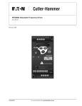
Fusion™ Series
Installation Manual
Industrial Control Unit
Model 57550-400
Model 57551-400
November 2004
Supersedes December 2003
IM05401001E (57550-900-02)
For more information visit: www.durant.com
Fusion Series
November 2004
Important Notice – Please Read
The product discussed in this literature is subject to terms and conditions outlined in Eaton
Electrical Inc. selling policies. The sole source governing the rights and remedies of any
purchaser of this equipment is the relevant Eaton Electrical Inc. selling policy.
NO WARRANTIES, EXPRESS OR IMPLIED, INCLUDING WARRANTIES OF FITNESS FOR A
PARTICULAR PURPOSE OR MERCHANTABILITY, OR WARRANTIES ARISING FROM COURSE
OF DEALING OR USAGE OF TRADE, ARE MADE REGARDING THE INFORMATION,
RECOMMENDATIONS AND DESCRIPTIONS CONTAINED HEREIN. In no event will Eaton
Electrical Inc. be responsible to the purchaser or user in contract, in tort (including
negligence), strict liability or otherwise for any special, indirect, incidental or consequential
damage or loss whatsoever, including but not limited to damage or loss of use of equipment,
plant or power system, cost of capital, loss of power, additional expenses in the use of
existing power facilities, or claims against the purchaser or user by its customers resulting
from the use of the information, recommendations and descriptions contained herein.
The information contained in this manual is subject to change without notice.
Cover Photo: Model 57550-400 Durant Fusion
IM05401001E (57550-900-02)
For more information visit: www.durant.com
i
Fusion Series
November 2004
Table of Contents
SAFETY
Definitions and Symbols . . . . . . . . . . . . . . . . . . . . . . . . . . . . . . . . . . . . . . . . . . . .
Warnings and Cautions . . . . . . . . . . . . . . . . . . . . . . . . . . . . . . . . . . . . . . . . . . . . .
iii
iv
INTRODUCTION . . . . . . . . . . . . . . . . . . . . . . . . . . . . . . . . . . . . . . . . . . . . . . . . . . . . . . . .
DESCRIPTION . . . . . . . . . . . . . . . . . . . . . . . . . . . . . . . . . . . . . . . . . . . . . . . . . . . . . . . . . .
Count Module . . . . . . . . . . . . . . . . . . . . . . . . . . . . . . . . . . . . . . . . . . . . . . . . . . . . .
Logic Control . . . . . . . . . . . . . . . . . . . . . . . . . . . . . . . . . . . . . . . . . . . . . . . . . . . . . .
Mounting Dimensions . . . . . . . . . . . . . . . . . . . . . . . . . . . . . . . . . . . . . . . . . . . . . .
1
1
1
2
3
WIRING AND DIP SWITCHES . . . . . . . . . . . . . . . . . . . . . . . . . . . . . . . . . . . . . . . . . . . . .
General Wiring Guidelines . . . . . . . . . . . . . . . . . . . . . . . . . . . . . . . . . . . . . . . . . . .
4
5
SPECIFICATIONS . . . . . . . . . . . . . . . . . . . . . . . . . . . . . . . . . . . . . . . . . . . . . . . . . . . . . . .
WARRANTY . . . . . . . . . . . . . . . . . . . . . . . . . . . . . . . . . . . . . . . . . . . . . . . . . . . . . . . . . . .
11
13
List of Figures
Figure 1: Approximate Dimensions in Inches (mm) . . . . . . . . . . . . . . . . . . . . . . .
Figure 2: Rear Terminal Layout . . . . . . . . . . . . . . . . . . . . . . . . . . . . . . . . . . . . . . .
Figure 3: DC Power Input (for DC Powered Model 57550400) . . . . . . . . . . . . . . .
Figure 4: AC Power Input (for AC Powered Model 57551400) . . . . . . . . . . . . . . .
Figure 5: High Speed Counter Inputs I15 – I17 and DIP Switches . . . . . . . . . . . .
Figure 6: High Speed Counter Input DIP Switch . . . . . . . . . . . . . . . . . . . . . . . . . .
Figure 7: Control Inputs I1 – I10 . . . . . . . . . . . . . . . . . . . . . . . . . . . . . . . . . . . . . . .
Figure 8: Analog Inputs I11 – I14 . . . . . . . . . . . . . . . . . . . . . . . . . . . . . . . . . . . . . .
Figure 9: Relay Outputs K1, K2 & K3 . . . . . . . . . . . . . . . . . . . . . . . . . . . . . . . . . . .
Figure 10: Relay Outputs K4 & K5 . . . . . . . . . . . . . . . . . . . . . . . . . . . . . . . . . . . . .
Figure 11: Transistor and Analog Outputs K6 – K9 . . . . . . . . . . . . . . . . . . . . . . . .
Figure 12: RS-232 Serial Port (DCE polarity) . . . . . . . . . . . . . . . . . . . . . . . . . . . . .
Figure 13: RS-485 Serial Port . . . . . . . . . . . . . . . . . . . . . . . . . . . . . . . . . . . . . . . . .
3
4
5
5
6
6
7
7
8
8
9
9
10
Table 1: DIP Switch Settings . . . . . . . . . . . . . . . . . . . . . . . . . . . . . . . . . . . . . . . . . .
Table 2: Fusion Technical Data . . . . . . . . . . . . . . . . . . . . . . . . . . . . . . . . . . . . . . . .
7
11
List of Tables
ii
For more information visit: www.durant.com
IM05401001E (57550-900-02)
Fusion Series
November 2004
Safety
Definitions and Symbols
WARNING
This symbol indicates high voltage. It calls your attention to items
or operations that could be dangerous to you and other persons
operating this equipment. Read the message and follow the
instructions carefully.
This symbol is the “Safety Alert Symbol.” It occurs with either of
two signal words: CAUTION or WARNING, as described below.
WARNING
Indicates a potentially hazardous situation which, if not avoided,
can result in serious injury or death.
CAUTION
Indicates a potentially hazardous situation which, if not avoided,
can result in minor to moderate injury, or serious damage to the
product. The situation described in the CAUTION may, if not
avoided, lead to serious results. Important safety measures are
described in CAUTION (as well as WARNING).
IM05401001E (57550-900-02)
For more information visit: www.durant.com
iii
Fusion Series
November 2004
Warnings and Cautions
WARNING
This device is an Open Type, Listed Process Control Equipment,
and must be mounted in an overall enclosure.
WARNING
To reduce the risk of fire or electrical shock, install in a controlled
environment relatively free of contaminants.
WARNING
Disconnect all power before wiring terminals. A safety hazard may
exist if this precaution is not observed. Treat all power and output
terminals as hazardous, since they may carry line voltage.
CAUTION
To reduce the risk of fire or electrical shock, do not interconnect the
outputs of different SELV, limited energy circuits.
CAUTION
Risk of electrical shock — more than one disconnect switch may be
required to de-energize the equipment before servicing.
CAUTION
This equipment generates, uses and can radiate radio frequency
energy and if not installed and used in accordance with the instruction
manual, may cause interference to radio communications. It has
been tested and found to comply with the limits for a Class A
computing device pursuant to Subpart J of Part 15 of FCC rules,
which are designed to provide reasonable protection against such
interference when operated in a commercial environment. Operation
of this equipment in a residential area is likely to cause interference
in which case the user at his own expense will be required to take
whatever measures may be required to correct the interference.
iv
For more information visit: www.durant.com
IM05401001E (57550-900-02)
Fusion Series
November 2004
Introduction
This manual describes the installation of the Durant® Fusion™ from Eaton Corporation,
Catalog Numbers 57550-400 (10 – 30V DC) and 57551-400 (85 – 265V AC). Following a brief
description of the control, this manual provides mounting and wiring information and
specifications. A separate user manual, Part Number 57590-900, gives programming,
operating and diagnostic information, and may be obtained by contacting the Durant
Literature Department at 800-540-9242, option 3 (US and Canada), or 920-261-4070,
option 3, or by fax at 920-261-9097. The user manual is also available from our website
at www.durant.com.
Description
The Durant Fusion from Eaton is an industrial control unit consisting of a high speed count
control module and a logic control capable of processing up to 100 rungs of ladder logic. The
Fusion also features a multi-line, alphanumeric display and 18 front panel input keys as an
operator interface. Configuration programming may be done using the display and keys, or
may be accomplished by serially downloading from a PC.
Count Module
The count module has two dedicated count inputs and a high speed reset input. These inputs
can be simultaneously used as ladder logic input contacts. The unit has 10 discreet control
inputs that can be used as counter control inputs and/or ladder logic inputs. Four analog
inputs, two 4 – 20 mA and two 0 – 10V, are dedicated to ladder comparators only.
The Fusion has three form C and two form A relay outputs, and two NPN transistor outputs.
These outputs can be individually assigned to counter functions, or as ladder outputs. Two
analog outputs, one 0 – 10V and one 4 – 20 mA, are also available. These outputs may be
used as followers assigned to count or rate functions, or as open loop control outputs from
the counter or the ladder.
The high speed count module is capable of counting at a sustained count speed of 6 kHz in any
of 13 count modes. The module consists of a ratemeter and three counters, a main counter, a
totalizer and a batch counter. The six digit main counter has up to five presets, plus prewarn.
The eight digit totalizer and six digit batch counter each have a single preset, and the five digit
ratemeter has two presets. Presets can be pre-loaded as “parameter sets” for programming
recipes or for job stacking. Up to 10 parameter sets are available. Both the main counter and
the totalizer are bi-directional (for up-down counting), and can be reset to zero, or to a selected
offset value. The batch counter counts up only, and can be reset to zero only.
IM05401001E (57550-900-02)
For more information visit: www.durant.com
1
Fusion Series
November 2004
Logic Control
The ladder logic processor can process a program of up to 100 rungs. Each rung can contain
up to six contacts and one coil. In addition to the 10 control inputs and three high speed
count inputs, contacts also include:
●
one power up signal
●
11 front panel keys
●
eight analog comparators for use with the four analog inputs
●
eight real time clock comparators
●
seven digital and two analog outputs
●
16 memory bits
●
16 display and print messages
●
eight counters
●
eight timers
●
one totalizer preset, one batch counter preset and two ratemeter presets (from the high
speed counter)
Coil types include:
2
●
seven digital and two analog outputs
●
16 memory bits
●
16 display and print messages
●
eight counters
●
eight timers
●
seven high speed counter inputs
●
nine high speed counter output unlatches
●
nine high speed counter output latches
For more information visit: www.durant.com
IM05401001E (57550-900-02)
Fusion Series
November 2004
Mounting Dimensions
WARNING
This device is an Open Type, Listed Process Control Equipment,
and must be mounted in an overall enclosure.
WARNING
To reduce the risk of fire or electrical shock, install in a controlled
environment relatively free of contaminants.
5.33 (135.5)
I-O
L1 L2
2.677± 0.028
(68 ± 0.7)
24V 6 7
8 9 RTN
1 2 3 4 5 6 7 8 9 10
11 12 13 14
12V 15 16 17
P/N 57551-400
5.433 ± 0.039
(138 ±1)
Recommended Panel Cutout
0.375 (9.5) Max. Panel Thickness
F1
F2
1
F4
Run
Program
Reset
F3
2
F5
3
F6
4
5
1
2
3
5
Enter
Edit
Clear
6
3.42
(86.9)
2.57
(65.3)
View
6.18 (157)
0.38
(9.7)
2.50 (63.5)
2.79 (70.8)
Figure 1: Approximate Dimensions in Inches (mm)
Mounting Instructions
1. Slide O ring gasket over unit body until it is tucked under the back of the front bezel.
2. Slide unit into cutout in panel.
3. Attach mounting clips and screws.
Tighten screws until the unit is firmly in place. DO NOT OVERTIGHTEN screws. Once the
bezel makes contact with the panel, further tightening may break the bezel.
IM05401001E (57550-900-02)
For more information visit: www.durant.com
3
Fusion Series
November 2004
Wiring and DIP Switches
All wiring to the Fusion is done to rear terminal, de-pluggable connectors. There are nine
headers on the back of the control to accept the wired connectors. The input and output
terminals are grouped by function, such as Power In, Outputs 1 – 3, RS-485, etc. in the
headers. Functions that are not needed for the application are simply left open. The same is
true for individual terminals on connectors that are not used. The wiring to each connector,
and the designation for each terminal is shown in the wiring diagrams below.
WARNING
Disconnect all power before wiring terminals. A safety hazard may
exist if this precaution is not observed. Treat all power and output
terminals as hazardous, since they may carry line voltage.
CAUTION
To reduce the risk of fire or electrical shock, do not interconnect the
outputs of different SELV, limited energy circuits.
CAUTION
Risk of electrical shock — more than one disconnect switch may be
required to de-energize the equipment before servicing.
A switch shall be included in the building installation:
●
It shall be in close proximity to the equipment and within easy reach of the operator.
●
It shall be marked as the disconnecting device for the equipment.
●
Switches and breakers in Europe must comply with IEC 947.
Transistor
and Analog
Outputs
Control
RS-232
Inputs Serial Port
Analog
Inputs
High Speed
Counter Inputs
RS-485
Serial
Port
Power Input
2 Terminals for
DC Powered Units
Relay Outputs
K1, K2, K3
Relay Outputs
K4, K5
3 Terminals for
AC Powered Units
Figure 2: Rear Terminal Layout
4
For more information visit: www.durant.com
IM05401001E (57550-900-02)
Fusion Series
November 2004
General Wiring Guidelines
1. Keep all signal wires as short as possible.
2. Use shielded cable for signal wiring.
3. Connect shielded cable drain wires to earth or machine ground.
4. Do not bundle signal wires with power wiring.
�
No Internal Fuse
External Fuse Size
U.S.
2.0A, 50V
Time
Delay
Power In +
10 – 30V DC –
15 VA
European
T2A, 50V
Time
Delay
�
Figure 3: DC Power Input (for DC Powered Model 57550400)
Terminal ratings: 10A, 380V AC, wire size 12 – 24 AWG (3.1 mm2 – 0.24 mm2) 600V
�
No Internal Fuse
External Fuse Size
U.S.
0.2A,
250V
Time
Delay
Power In
85 – 265V AC
47 – 63 Hz
20 VA
European
T200 mA,
250V
Time
Delay
�
Figure 4: AC Power Input (for AC Powered Model 57551400)
Terminal ratings: 10A, 250V AC, wire size 12 – 24 AWG (3.1 mm2 – 0.24 mm2) 600V
IM05401001E (57550-900-02)
For more information visit: www.durant.com
5
Fusion Series
November 2004
Ground
Input I17
Input I16
Input I15
+ 12V DC
High Speed Counter Input
Terminal Identification:
Input I15 – Count Input A
Input I16 – Count Input B
Input I17 – Reset Input
Sensor Power Out:
12V DC +/– 10%, 75 mA max.,
short circuit protected.
Typical Count Input Wiring
(Match DIP Switch Settings to Input)
NPN
A, B,
Reset
Contact
A, B,
Reset
PNP
(30V DC Max.)
Mag
Pickup
A
A, B
For 95 – 130V AC/DC signals, use Durant 36059450 input module or equivalent.
Figure 5: High Speed Counter Inputs I15 – I17 and DIP Switches
Terminal ratings: 8A, 125V AC, wire size 16 – 28 AWG (1.3 mm2 – 0.1 mm2) 600V
DIP Switch
1
6
Figure 6: High Speed Counter Input DIP Switch
Set the DIP switches to electrically match the type of input wired to count inputs A and B, and
the reset input. “Sink” refers to an NPN or contact input as shown in Figure 5. “Source”
refers to a PNP input as shown in Figure 5. For any of the inputs used, set all of the switches
for that input to the proper setting as determined by Table 1. If a mag input is wired to input
A, switch 1 must be set to Source. Slow response is 140 Hz maximum for NPN, push-pull, and
mag inputs, and 60 Hz maximum for PNP inputs. Fast response is 14 kHz maximum.
6
For more information visit: www.durant.com
IM05401001E (57550-900-02)
Fusion Series
November 2004
Table 1: DIP Switch Settings
DIP Switch Number
“1” Setting
“0” Setting
1
A Input Sink
A Input Source
2
A Input Slow Response
A Input Fast Response
3
A Input Mag Pickup
A Input Single Ended
4
B Input Sink
B Input Source
5
B Input Slow Response
B Input Fast Response
6
Reset Input Slow Response
Reset Input Fast Response
Ground
Input I1
Typical Control Input Wiring
Input I10
Ground
NPN
I1 - I10
Contact
I1 - I10
For 95 – 130V AC/DC signals,
use Durant 36059450 input
module or equivalent.
For 10 – 32V DC or 15 – 32V AC
signals, use Durant 36059451
input module or equivalent.
Figure 7: Control Inputs I1 – I10
Terminal ratings: 8A, 125V AC, wire size 16 – 28 AWG (1.3 mm2 – 0.1 mm2) 600V
Ground
Input I14
Input I13
Input I12
Input I11
Ground
Analog Input Terminal Identification:
I11 4 – 20 mA Input
I12 0 – 10V Input
I13 4 – 20 mA Input
I14 0 – 10V Input
Typical Analog Input Wiring
4 – 20 mA
Control
Powered Loop
+
–
or
Sensor
Powered
Loop
+24V DC
I11, I13
+
–
I11, I13
Ground
0 – 10V
I12, I14
Ground
+
–
Figure 8: Analog Inputs I11 – I14
Terminal ratings: 8A, 125V AC, wire size 16 – 28 AWG (1.3 mm2 – 0.1 mm2) 600V
IM05401001E (57550-900-02)
For more information visit: www.durant.com
7
Fusion Series
November 2004
Com
NC
NO
Com
Output K2 NC
NO
Com
Output K3 NC
NO
Output K1
An RC surge suppressor
is recommended across
all inductive loads, Durant
part number 38091400 or
equivalent for most applications.
Figure 9: Relay Outputs K1, K2 & K3
Terminal ratings: 10A, 250V AC, wire size 12 – 24 AWG (3.1 mm2 – 0.24 mm2) 600V
Com
NO
Com
Output K5
NO
Output K4
An RC surge suppressor
is recommended across
all inductive loads, Durant
part number 38091400 or
equivalent for most applications.
Figure 10: Relay Outputs K4 & K5
Terminal ratings: 10A, 250V AC, wire size 12 – 24 AWG (3.1 mm2 – 0.24 mm2) 600V
8
For more information visit: www.durant.com
IM05401001E (57550-900-02)
Fusion Series
November 2004
Transistor /Analog Output Terminal Description:
Output K6 – NPN Open Collector Output
Output K7 – NPN Open Collector Output
Output K8 – the Positive (+) Side of the Isolated 4 – 20 mA Output
Output K9 – the Positive (+) Side of the Isolated 0 – 10V Output
Analog Output Return –
the Negative (-) Side of Isolated 4 – 20 mA and 0 – 10V Outputs
Analog Output Return
Output K9
Output K8
Ground
Output K7
Output K6
+24V DC
Sensor Power Out:
24V DC +/– 15%, 100 mA max., short circuit protected,
at +24V DC with respect to the ground terminal.
Typical Transistor and Analog Out Wiring
(Match DIP Switch Settings to Input)
4 – 20 mA Out
Transistor Out
0 – 10V Out
V+ (30V DC Max.)
K8
�
Analog
Out Return
+
>450Ω
–
K9
Analog
Out Return
+
>2500Ω
–
K6, K7
150 mA Max.
Ground
V-
� Suppress inductive loads with a diode, 1N4004 or equivalent.
Figure 11: Transistor and Analog Outputs K6 – K9
Terminal ratings: 10A, 250V AC, wire size 12 – 24 AWG (3.1 mm2 – 0.24 mm2) 600V
Receive Data Out (Pin 2)
Transmit Data In (Pin 3)
Data Terminal Ready In (Pin 4)
Ground (Pin 5)
Figure 12: RS-232 Serial Port (DCE polarity)
Mating connector: DB-9P
IM05401001E (57550-900-02)
For more information visit: www.durant.com
9
Fusion Series
November 2004
Common
RS-485 +
RS-485 –
RS-485 –
RS-485 +
Common
Figure 13: RS-485 Serial Port
Mating connector: RJ-12 plug
Typical wiring: Both commons are connected inside the control, as are both RS-485+
terminals, and both RS-485- terminals. Connect all devices on the RS-485 network + to +,
- to -, and common to common, using three-conductor cable.
10
For more information visit: www.durant.com
IM05401001E (57550-900-02)
Fusion Series
November 2004
Specifications
Table 2: Fusion Technical Data
Description
Specifications
Environmental
Operation
Indoor use to 2000m
Temperature
32° to 122°F (0° to 50°C) operating;
-4° to 158°F (-20° to 70°C) storage
Humidity
0 to 85% RH, non-condensing
Vibration
2.5 Gs, 30 – 200 Hz
Shock
30 Gs, 11 mS half sinewave
EMC
EN61326:1997
All I/O lines except RS-485 <30m
Front Panel
Type 4X indoor use only, when mounted with gasket provided
Safety
UL, cUL Listed, CE Compliant
Mechanical
Cutout
138 mm x 68 mm DIN standard
Outline
157 mm x 87 mm x 81 mm
Panel depth
72 mm maximum
Enclosure
Polycarbonate/ABS
Label
Polyester
Input Power
AC Model
85 – 265V AC, 47 – 63 Hz, 20 VA; Isolation 2300V AC
DC Model
10 – 30V DC, 15 VA
Inputs
Control:
Number
Impedance
Thresholds
Counter:
Number
Impedance
Thresholds
Response
Analog:
Number
Type
Accuracy
Impedance
Overrange
IM05401001E (57550-900-02)
10
4.75k Ohms to +5V DC
High 3.5 – 30V DC; Low 0 – 1.0V DC
3 (including reset)
4.75k Ohms to +5V DC or 26.9k Ohms to ground
High 3.5 – 30V; Low 0 – 1.5V, or 200 mV p-p to 50V rms
@ 26.9k Ohms (mag pickup)
140 Hz or 14 kHz for sinking, push-pull or mag pickup inputs
60 Hz or 6 kHz for sourcing only inputs
All frequencies based on 50-50 duty cycle
6 kHz maximum sustained count speed
4
4 – 20 mA and two 0 – 10V DC
+/- 0.5% FS and +/- 200 PPM/°C
100 Ohms (current input), 1.27M Ohms (voltage input)
45 mA maximum (current input), 20V maximum (voltage input)
For more information visit: www.durant.com
11
Fusion Series
November 2004
Table 2: Fusion Technical Data (continued)
Description
Specifications
Outputs
Power
24V DC +/- 15%, 100 mA maximum, short circuit protected
12V DC +/- 10%, 75 mA maximum, short circuit protected
Relays:
Number
Contacts
Isolation
3 (Form C), 2 (Form A)
5A, 250V AC, 30V DC
2300V AC
Transistors:
Number
Type
Ratings
2
NPN Darlington
150 mA maximum ON current, 30V DC maximum OFF voltage
Analog:
Number
Type
Accuracy
Common Mode Voltage Rating
Isolation
2, short circuit protected
4 – 20 mA (<450 Ohms), 0 – 10V (>2500 Ohms)
+/- 0.5% FS and +/- 200 PPM/°C
250V AC
2300V AC
RS-232:
Connector
Polarity
Baud Rate
DB-9S
DCE
1200 – 19200
RS-485:
Connector
Baud Rate
6 wire RJ-12 phonejack
1200 – 19200
Data Retention
Program Data:
Type
Duration
Non-volatile
100 Years, no batteries
Real Time Clock:
Type
Charge Time
Retention
Capacitor
3 Minutes
1 – 5 Days
Human Interface
Display:
Type
Character Size
12
128 x 64 pixel graphic LCD with LED backlight
0.12" high, 21 characters per line, 6 lines maximum
0.24" high, 10 characters per line, 3 lines maximum
0.35" high, 7 characters per line, 2 lines maximum
Keys:
Number
Type
18
membrane switches with tactile feedback
Real Time Clock Format
Seconds, minutes, hours, day and date
For more information visit: www.durant.com
IM05401001E (57550-900-02)
Fusion Series
November 2004
Warranty
Seller warrants that the Products manufactured by it will conform to Seller’s applicable
specifications and be free from failure due to defects in workmanship and material for one (1)
year from the date of installation of the Product or eighteen (18) months from the date of
shipment of the Product, whichever occurs first.
In the event any Product fails to comply with the foregoing warranty Seller will, at its option,
either (a) repair or replace the defective Product, or defective part or component thereof, F.O.B.
Seller’s facility freight prepaid, or (b) credit Buyer for the purchase price of the Product. All
warranty claims shall be made in writing. Seller requires all non-conforming Products be
returned at Seller’s expense for evaluation unless specifically stated otherwise in writing by
Seller.
This warranty does not cover failure or damage due to storage, installation, operation or
maintenance not in conformance with Seller’s recommendations and industry standard practice
or due to accident, misuse, abuse or negligence. This warranty does not cover reimbursement
for labor, gaining access, removal, installation, temporary power or any other expenses which
may be incurred in connection with repair or replacement.
This warranty does not apply to equipment not manufactured by Seller. Seller limits itself to
extending the same warranty it receives from the supplier.
Limitation on Warranties for Products, Services and Power Systems Studies
THE FOREGOING WARRANTIES ARE EXCLUSIVE EXCEPT FOR WARRANTIES OF TITLE AND
AGAINST PATENT INFRINGEMENT. SELLER DISCLAIMS ALL OTHER WARRANTIES INCLUDING
ANY IMPLIED WARRANTIES OF MERCHANTABILITY AND FITNESS FOR A PARTICULAR
PURPOSE.
CORRECTION OF NON-CONFORMITIES IN THE MANNER AND FOR THE PERIOD OF TIME
PROVIDED ABOVE SHALL CONSTITUTE SELLER’S SOLE LIABILITY AND BUYER’S EXCLUSIVE
REMEDY FOR FAILURE OF SELLER TO MEET ITS WARRANTY OBLIGATIONS, WHETHER
CLAIMS OF THE BUYER ARE BASED IN CONTRACT, IN TORT (INCLUDING NEGLIGENCE OR
STRICT LIABILITY), OR OTHERWISE.
IM05401001E (57550-900-02)
For more information visit: www.durant.com
13
Company Information
Eaton’s electrical business is a global leader in electrical control, power distribution, and
industrial automation products and services. Through advanced product development,
world-class manufacturing methods, and global engineering services and support,
Eaton’s electrical business provides customer-driven solutions under brand names such
as Cutler-Hammer®, Powerware®, Durant®, Heinemann®, Holec® and MEM®, which
globally serve the changing needs of the industrial, utility, light commercial, residential,
and OEM markets. For more information, visit www.EatonElectrical.com.
Eaton Corporation is a diversified industrial manufacturer with 2003 sales of $8.1 billion.
Eaton is a global leader in fluid power systems and services for industrial, mobile and
aircraft equipment; electrical systems and components for power quality, distribution and
control; automotive engine air management systems and powertrain controls for fuel
economy; and intelligent drivetrain systems for fuel economy and safety in trucks. Eaton
has 55,000 employees and sells products to customers in more than 100 countries. For
more information, visit www.eaton.com.
Eaton Electrical Inc.
1000 Cherrington Parkway
Moon Township, PA 15108-4312
USA
tel: 1-800-525-2000
www.EatonElectrical.com
Durant Products
901 S. 12th Street
Watertown, WI 53094
USA
tel: 1-920-261-4070
tel: 1-800-540-9242
www.durant.com
© 2004 Eaton Corporation
All Rights Reserved
Printed in USA
Publication No. IM05401001E (57550-900-02)/CPG
November 2004