1
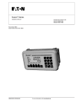
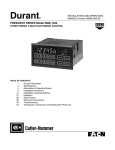
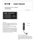
Fusion™ Series
Technical Data
New Information
December 2003
Product Description
Durant®
The
Fusion from Eaton
Electrical® is an industrial control unit
consisting of a high speed count control module and a logic control capable of processing up to 100 rungs of
ladder logic. The Fusion also features
a multi-line, alphanumeric display and
18 front panel input keys as an operator interface. Configuration programming may be done using the display
and keys, or may be accomplished by
serially downloading from a PC.
Durant Fusion
Description
Page
Product Description . . . . . . . . . . . .
Features and Benefits . . . . . . . . . .
Technical Data and
Specifications . . . . . . . . . . . . . . .
Wiring Diagrams . . . . . . . . . . . . . .
Dimensions . . . . . . . . . . . . . . . . . .
Product Selection. . . . . . . . . . . . . .
The count module has two dedicated
count inputs and a high speed reset
input. These inputs can be simultaneously used as ladder logic input
contacts. The unit has 10 discreet control inputs that can be used as counter
control inputs and/or ladder logic inputs.
Four analog inputs, two 4 – 20 mA and
two 0 – 10V, are dedicated to ladder
comparators only.
and can be reset to zero, or to a
selected offset value. The batch
counter counts up only, and can be
reset to zero only.
The Fusion has three form C and two
form A relay outputs, and two NPN
transistor outputs. These outputs can
be individually assigned to counter
functions, or as ladder outputs. Two
analog outputs, one 0 – 10V and one
4 – 20 mA, are also available. These
outputs may be used as followers
assigned to count or rate functions, or
as open loop control outputs from the
counter or the ladder.
■
■
■
The high speed count module is capable of counting at a sustained count
speed of 6 kHz in any of 13 count
modes. The module consists of a ratemeter and three counters, a main
counter, a totalizer and a batch counter.
The six digit main counter has up to
five presets, plus prewarn. The eight
digit totalizer and six digit batch
counter each have a single preset, and
the five digit ratemeter has two presets. Presets can be pre-loaded as
“parameter sets” for programming
recipes or for job stacking. Up to 10
parameter sets are available. Both the
main counter and the totalizer are bidirectional (for up-down counting),
TD05401001E
Contents
For more information visit: www.durant.com
1
2
2
3
8
8
The ladder logic processor can process
a program of up to 100 rungs. Each
rung can contain up to six contacts
and one coil. In addition to the 10 control inputs and three high speed count
inputs, contacts also include:
■
■
■
■
■
■
■
one power up signal
11 front panel keys
eight analog comparators for use
with the four analog inputs
eight real time clock comparators
seven digital and two analog outputs
16 memory bits
16 display and print messages
eight counters
eight timers
one totalizer preset, one batch
counter preset and two ratemeter
presets (from the high speed
counter)
Coil types include:
■
■
■
■
■
■
■
seven digital and two analog outputs
16 memory bits
16 display and print messages
eight counters
eight timers
seven high speed counter inputs
nine high speed counter output
unlatches
■ nine high speed counter output
latches
Technical Data
Page 2
Fusion™ Series
Effective: December 2003
Features and Benefits
■
Table 1. Features and Benefits
Feature
Customer Benefit
High speed count functions; including scaling,
main counter, five presets, prewarn, totalizer,
batch and rate
“Canned” count functions offer flexibility and
ease of setup in the desired units of measure.
High speed counting independent of ladder scan Precise and repeatable output response for high
time
performance applications.
Flexible display with selectable character sizes
(large, medium, small), run screens and ladder
triggered messages.
Simple front panel layout and keypad. Four soft
keys & six function keys can be used as inputs.
Minimizes confusion and operator errors as
information can be tailored to what they need
and in their language. Maintenance/management data can be separated. Different character
sizes allow optimization of information displayed. Machine status information can be displayed allowing operators to take action.
Ease of use for operator. Numeric keypad allows
for ease of preset and machine parameter entry.
Function keys and soft keys allow easy and quick
access to information and/or parameters needed
by the operator and don’t require using additional inputs. Eliminates cost associated with
external pushbuttons and inputs.
Parameter sets
Allows for predefined recipes/jobs to be preloaded for the operator. Simplifies operator
interaction and minimizes errors.
Programmable relay logic
Well understood programming method that
allows flexibility in control functionality. Easy to
tailor the control to various applications.
26 I/O (digital & analog)
Provides application flexibility. Analog inputs
allow monitoring key process parameters. Analog outputs allow interfacing to drives and other
control products.
Integrated solution
Reduced overall control costs, installation and
commissioning. More flexible and capable than
traditional count/control solutions but less complex than many PLC solutions.
Windows® and front panel programming
Ease of programming and configuration control.
RS-232 and RS-485 serial communication ports
Allow for direct connection to PC for programming, connection to Modbus® networks, interface to serial printer.
Robust type 4X package. DIN cutout and short
depth 2.82 Inches (71.6 mm).
Suited for wet applications. Same cutout as the
President Series — easing the migration. Short
depth minimizes the cost and size of the
machine panel or control enclosure.
Input power:
85 – 265V AC 50/60 Hz or 10 – 30V DC models
Greatly reduces models required for different
control voltages.
Output power:
12V DC @75 mA, 24V DC @100 mA
Eliminates the need for an external power supply for encoders, analog transducers, etc.
Depluggable screw terminals
Allows for ease of wiring and removal of control.
Terminals are different sizes to error-proof
installation.
Non-volatile memory and capacitor backed real
time clock
Don’t have to worry about a battery failing down
the road.
Real time clock
Allows for control functions to be performed on
day/time and allows for date/time stamping on
printouts.
UL, cUL and CE marked
Ease of meeting machine agency requirements
and robust EMC performance.
Technical Data and Specifications
Environmental
■
■
Operation: Indoor use to 2000m
Temperature:
❑ 32° to 122°F (0° to 50°C) operating
❑ -4° to 158°F (-20° to 70°C) storage
■
Humidity: 0 to 85% RH,
non-condensing
■ Vibration: 2.5 Gs, 30 – 200 Hz
■ Shock: 30 Gs, 11 mS half
sinewave
For more information visit: www.durant.com
EMC:
❑ EN61326:1997
❑ All I/O lines except RS-485 <30m
■
Front Panel:
Type 4X indoor use only, when
mounted with gasket provided
■ Safety: UL, cUL Listed, CE Compliant
❑
Mechanical
■
■
■
■
■
Cutout: 138 mm x 68 mm DIN
standard
Outline: 157 mm x 87 mm x 81 mm
Panel depth: 72 mm maximum
Enclosure: Polycarbonate/ABS
Label: Polyester
Input Power
■
AC Model: 85 – 265V AC, 47 – 63 Hz,
20 VA; Isolation 2300V AC
■ DC Model: 10 – 30V DC, 15 VA
Inputs
■
Control:
❑ Number: 10
❑ Impedance: 4.75k Ohms to +5V DC
❑ Thresholds:
– High 3.5 – 30V DC
– Low 0 – 1.0V DC
■ Counter:
❑ Number: 3 (including reset)
❑ Impedance : 4.75k Ohms to +5V DC
or 26.9k Ohms to ground
❑ Thresholds:
– High 3.5 – 30V
– Low 0 – 1.5V, or 200 mV p-p to
50V rms @ 26.9k Ohms (mag
pickup)
❑ Response:
– 140 Hz or 14 kHz for sinking,
push-pull or mag pickup inputs
– 60 Hz or 6 kHz for sourcing only
inputs
– All frequencies based on 50-50
duty cycle
– 6 kHz maximum sustained
count speed
■ Analog:
❑ Number: 4
❑ Type: 4 – 20 mA and two 0 – 10V DC
❑ Accuracy: +/- 0.5% FS and
+/- 200 PPM/°C
❑ Impedance: 100 Ohms (current
input), 1.27M Ohms (voltage input)
❑ Overrange: 45 mA max. (current
input), 20V max. (voltage input)
TD05401001E
Fusion™ Series
Technical Data
Effective: December 2003
Outputs
■
■
■
■
■
■
Power (AC input model only):
❑ 24V DC +/- 15%, 100 mA max.,
short circuit protected
❑ 12V DC +/- 10%, 75 mA max.,
short circuit protected
Relays:
❑ Number: 3 (Form C), 2 (Form A)
❑ Contacts: 5A, 250V AC, 30V DC
❑ Isolation: 2300V AC
Transistors:
❑ Number: 2
❑ Type: NPN Darlington
❑ Ratings: 150 mA max. ON current,
30V DC max. OFF voltage
Analog:
❑ Number: 2, short circuit protected
❑ Type: 4 – 20 mA (<450 Ohms),
0 – 10V (>2500 Ohms)
❑ Accuracy: +/- 0.5% FS and
+/- 200 PPM/°C
❑ Common Mode Voltage Rating:
250V AC
❑ Isolation: 2300V AC
RS-232:
❑ Connector: DB-9S
❑ Polarity: DCE
❑ Baud Rate: 1200 – 19200
RS-485:
❑ Connector: 6 wire RJ-12 phonejack
❑ Baud Rate: 1200 – 19200
Page 3
Table 2. DIP Switch Settings
DIP Switch Number
“1” Setting
“0” Setting
1
A Input Sink
A Input Source
2
A Input Slow Response
A Input Fast Response
3
A Input Mag Pickup
A Input Single Ended
4
B Input Sink
B Input Source
5
B Input Slow Response
B Input Fast Response
6
Reset Input Slow Response
Reset Input Fast Response
Wiring Diagrams
Transistor
and Analog
Outputs
Control
RS-232
Inputs Serial Port
Analog
Inputs
High Speed
Counter Inputs
RS-485
Serial
Port
Power Input
2 Terminals for
DC Powered Units
Relay Outputs
K1, K2, K3
Relay Outputs
K4, K5
3 Terminals for
AC Powered Units
Data Retention
■
Program Data:
❑ Type: Non-volatile
❑ Duration: 100 Years, no batteries
■
Real Time Clock:
Type: Capacitor
❑ Charge Time: 3 Minutes
❑ Retention: 1 – 5 Days
Figure 1. Rear Terminal Layout
❑
�
U.S.
2.0A, 50V
Time
Delay
Human Interface
■
Display:
❑ Type: 128 x 64 pixel graphic LCD
with LED backlight
❑ Character Size:
– 0.12" high, 21 characters per
line, 6 lines maximum
– 0.24" high, 10 characters per
line, 3 lines maximum
– 0.35" high, 7 characters per
line, 2 lines maximum
■ Keys:
❑ Number: 18
❑ Type: membrane switches with
tactile feedback
■ Real Time Clock Format: Seconds,
minutes, hours, day and date
TD05401001E
No Internal Fuse
External Fuse Size
Power In +
10 – 30V DC –
15 VA
European
T2A, 50V
Time
Delay
�
Figure 2. DC Power Input (for DC powered model 57550400)
Terminal ratings: 10A, 380V AC, wire size 12 – 24 AWG (3.1 mm2 – 0.24 mm2) 600V
For more information visit: www.durant.com
Technical Data
Page 4
Fusion™ Series
Effective: December 2003
�
No Internal Fuse
External Fuse Size
U.S.
0.2A,
250V
Time
Delay
Power In
85 – 265V AC
47 – 63 Hz
20 VA
European
T200 mA,
250V
Time
Delay
�
Figure 3. AC Power Input (for AC powered model 57551400)
Terminal ratings: 10A, 250V AC, wire size 12 – 24 AWG (3.1 mm2 – 0.24 mm2) 600V
Ground
Input I17
Input I16
Input I15
+ 12V DC
High Speed Counter Input
Terminal Identification:
Input I15 – Count Input A
Input I16 – Count Input B
Input I17 – Reset Input
Sensor Power Out:
12V DC +/– 10%, 75 mA max.,
short circuit protected.
Typical Count Input Wiring
(Match DIP Switch Settings to Input)
NPN
A, B,
Reset
Contact
A, B,
Reset
PNP
(30V DC Max.)
Mag
Pickup
A
A, B
For 95 – 130V AC/DC signals, use Durant 36059450 input module or equivalent.
Figure 4. High Speed Counter Inputs I15 – I17 and DIP Switches
Terminal ratings: 8A, 125V AC, wire size 16 – 28 AWG (1.3 mm2 – 0.1 mm2) 600V
For more information visit: www.durant.com
TD05401001E
Fusion™ Series
Technical Data
Effective: December 2003
Ground
Input I1
Typical Control Input Wiring
Input I10
Ground
NPN
I1 - I10
Contact
I1 - I10
For 95 – 130V AC/DC signals,
use Durant 36059450 input
module or equivalent.
For 10 – 32V DC or 15 – 32V AC
signals, use Durant 36059451
input module or equivalent.
Figure 5. Control Inputs I1 – I10
Terminal ratings: 8A, 125V AC, wire size 16 – 28 AWG (1.3 mm2 – 0.1 mm2) 600V
Ground
Input I14
Input I13
Input I12
Input I11
Ground
Analog Input Terminal Identification:
I11 4 – 20 mA Input
I12 0 – 10V Input
I13 4 – 20 mA Input
I14 0 – 10V Input
Typical Analog Input Wiring
4 – 20 mA
Control
Powered Loop
+
–
or
Sensor
Powered
Loop
+24V DC
I11, I13
+
–
I11, I13
Ground
0 – 10V
I12, I14
Ground
+
–
Figure 6. Analog Inputs I11 – I14
Terminal ratings: 8A, 125V AC, wire size 16 – 28 AWG (1.3 mm2 – 0.1 mm2) 600V
Com
NC
NO
Com
Output K2 NC
NO
Com
Output K3 NC
NO
Output K1
An RC surge suppressor
is recommended across
all inductive loads, Durant
part number 38091400 or
equivalent for most applications.
Figure 7. Relay Outputs K1, K2 and K3
Terminal ratings: 10A, 250V AC, wire size 12 – 24 AWG (3.1 mm2 – 0.24 mm2) 600V
TD05401001E
For more information visit: www.durant.com
Page 5
Technical Data
Page 6
Fusion™ Series
Effective: December 2003
Com
NO
Com
Output K5
NO
An RC surge suppressor
is recommended across
all inductive loads, Durant
part number 38091400 or
equivalent for most applications.
Output K4
Figure 8. Relay Outputs K4 and K5
Terminal ratings: 10A, 250V AC, wire size 12 – 24 AWG (3.1 mm2 – 0.24 mm2) 600V
Transistor /Analog Output Terminal Description:
Output K6 – NPN Open Collector Output
Output K7 – NPN Open Collector Output
Output K8 – the Positive (+) Side of the Isolated 4 – 20 mA Output
Output K9 – the Positive (+) Side of the Isolated 0 – 10V Output
Analog Output Return –
the Negative (-) Side of Isolated 4 – 20 mA and 0 – 10V Outputs
Analog Output Return
Output K9
Output K8
Ground
Output K7
Output K6
+24V DC
Sensor Power Out:
24V DC +/– 15%, 100 mA max., short circuit protected,
at +24V DC with respect to the ground terminal.
Typical Transistor and Analog Out Wiring
(Match DIP Switch Settings to Input)
4 – 20 mA Out
Transistor Out
0 – 10V Out
V+ (30V DC Max.)
K8
�
Analog
Out Return
+
>450Ω
–
K9
Analog
Out Return
+
>2500Ω
–
K6, K7
150 mA Max.
Ground
V-
� Suppress inductive loads with a diode, 1N4004 or equivalent.
Figure 9. Transistor and Analog Outputs K6 – K9
Terminal ratings: 10A, 250V AC, wire size 12 – 24 AWG (3.1 mm2 – 0.24 mm2) 600V
For more information visit: www.durant.com
TD05401001E
Fusion™ Series
Technical Data
Effective: December 2003
Receive Data Out (Pin 2)
Transmit Data In (Pin 3)
Data Terminal Ready In (Pin 4)
Ground (Pin 5)
Figure 10. RS-232 Serial Port (DCE polarity)
Mating connector: DB-9P
Common
RS-485 +
RS-485 –
RS-485 –
RS-485 +
Common
Figure 11. RS-485 Serial Port
Mating connector: RJ-12 plug
Typical wiring: Both commons are connected inside the control, as are both RS-485+
terminals and both RS-485- terminals. Connect all devices on the RS-485 network + to +, - to
- and common to common, using three conductor cable.
TD05401001E
For more information visit: www.durant.com
Page 7
Technical Data
Page 8
Fusion™ Series
Effective: December 2003
Dimensions
Product Selection
Table 3. Fusion Product Selection
5.33 (135.5)
Input
Power
Catalog
Number
10 – 30V DC
57550-400
85 – 265V AC
57551-400
I-O
L1 L2
24V 6 7
Table 4. Accessories
8 9 RTN
1 2 3 4 5 6 7 8 9 10
11 12 13 14
12V 15 16 17
P/N 57551-400
3.42
(86.9)
F1
F2
1
F4
Run
Reset
Program
F3
2
F5
3
F6
4
5
6
1
2
3
5
Enter
View
Edit
Clear
2.57
(65.3)
6.18 (157)
2.50 (63.5)
2.79 (70.8)
0.38
(9.7)
2.677± 0.028
(68 ± 0.7)
5.433 ± 0.039
(138 ±1)
Description
Catalog
Number
Windows Programming
Software & User Manual
57590-400
AC (95 – 130) to DC
Input Module – Wire Leads
36059-450
Eight Slot I/O Module
Mounting Board
58490-444
120V AC Input Module
36059-200
DC (10 – 32V) Input Module
36059-201
240V AC Input Module
36059-206
Analog to Frequency
Converter
48160-45X
Surge Suppressor
38091-400
Comm Converter, RS-485/
RS-232 with Terminals
58801-461
Comm Converter, RS-485/
RS-232 with AC Line Cord
58801-460
Medium Duty, Single Channel 38150-XXX
Shaft Encoder
Medium Duty, Quadrature
Shaft Encoder
38151-XXX
Heavy Duty, Single Channel
Shaft Encoder
48370-XXX
Heavy Duty, Quadrature Shaft 48371-XXX
Encoder
Mating Connector and
Encoder Cable (10')
29665-300
Rotary Contactor
41100-4XX
39100-4XX
Vane Pickup
39400-400
Solid-State Relays
E45 Series
Desk Mounting Kit
58802-420
Recommended Panel Cutout
0.375 (9.5) Max. Panel Thickness
Figure 12. Approximate Dimensions in Inches (mm)
Eaton Electrical
1000 Cherrington Parkway
Moon Township, PA 15108-4312
USA
tel: 1-800-525-2000
www.eatonelectrical.com
Durant Products
901 S. 12th Street
Watertown, WI 53094
USA
tel: 1-920-261-4070
tel: 1-800-540-9242
www.durant.com
© 2003 Eaton Corporation
All Rights Reserved
Printed in USA
Publication No. TD05401001E/CPG
December 2003