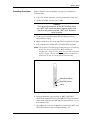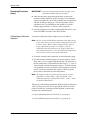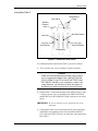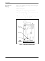
1
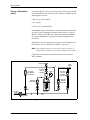
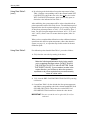
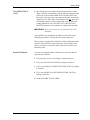
Model MG101
Field Calibration
System
January 2004
Process Control Instruments
Model MG101
Field Calibration System
User’s Manual
910-115B
January 2004
MG101 Field Calibration System
iii
January 2004
Warranty
Each instrument manufactured by GE Panametrics is warranted to be
free from defects in material and workmanship. Liability under this
warranty is limited to restoring the instrument to normal operation or
replacing the instrument, at the sole discretion of GE Panametrics. Fuses
and batteries are specifically excluded from any liability. This warranty
is effective from the date of delivery to the original purchaser. If GE
Panametrics determines that the equipment was defective, the warranty
period is:
•
one year for general electronic failures of the instrument
•
one year for mechanical failures of the sensor
If GE Panametrics determines that the equipment was damaged by
misuse, improper installation, the use of unauthorized replacement parts,
or operating conditions outside the guidelines specified by GE
Panametrics, the repairs are not covered under this warranty.
The warranties set forth herein are exclusive and are in lieu of
all other warranties whether statutory, express or implied
(including warranties or merchantability and fitness for a
particular purpose, and warranties arising from course of
dealing or usage or trade).
Return Policy
If a GE Panametrics instrument malfunctions within the warranty period,
the following procedure must be completed:
1. Notify GE Panametrics, giving full details of the problem, and
provide the model number and serial number of the instrument. If the
nature of the problem indicates the need for factory service, GE
Panametrics will issue a RETURN AUTHORIZATION NUMBER
(RAN), and shipping instructions for the return of the instrument to a
service center will be provided.
2. If GE Panametrics instructs you to send your instrument to a service
center, it must be shipped prepaid to the authorized repair station
indicated in the shipping instructions.
3. Upon receipt, GE Panametrics will evaluate the instrument to
determine the cause of the malfunction.
Then, one of the following courses of action will then be taken:
iv
•
If the damage is covered under the terms of the warranty, the
instrument will be repaired at no cost to the owner and returned.
•
If GE Panametrics determines that the damage is not covered under
the terms of the warranty, or if the warranty has expired, an estimate
for the cost of the repairs at standard rates will be provided. Upon
receipt of the owner’s approval to proceed, the instrument will be
repaired and returned.
January 2004
Table of Contents
Introduction . . . . . . . . . . . . . . . . . . . . . . . . . . . . . . . . . . . . . . . . . . . . . . . . . . . . . . . . . . . . . . . . . . . 1
Theory Of Operation . . . . . . . . . . . . . . . . . . . . . . . . . . . . . . . . . . . . . . . . . . . . . . . . . . . . . . . . . . . . 1
Initial Considerations. . . . . . . . . . . . . . . . . . . . . . . . . . . . . . . . . . . . . . . . . . . . . . . . . . . . . . . . . . . . 3
Operating Range . . . . . . . . . . . . . . . . . . . . . . . . . . . . . . . . . . . . . . . . . . . . . . . . . . . . . . . . . . . . 3
Operating Environment. . . . . . . . . . . . . . . . . . . . . . . . . . . . . . . . . . . . . . . . . . . . . . . . . . . . . . . 3
Operating Requirements . . . . . . . . . . . . . . . . . . . . . . . . . . . . . . . . . . . . . . . . . . . . . . . . . . . . . . 4
Preliminary Setup . . . . . . . . . . . . . . . . . . . . . . . . . . . . . . . . . . . . . . . . . . . . . . . . . . . . . . . . . . . . . . 5
Operating Procedure . . . . . . . . . . . . . . . . . . . . . . . . . . . . . . . . . . . . . . . . . . . . . . . . . . . . . . . . . . . . 7
Calibrating the Moisture Samples. . . . . . . . . . . . . . . . . . . . . . . . . . . . . . . . . . . . . . . . . . . . . . . 8
Using Data Table 3 . . . . . . . . . . . . . . . . . . . . . . . . . . . . . . . . . . . . . . . . . . . . . . . . . . . . . . . . . . 9
Using Data Table 2 . . . . . . . . . . . . . . . . . . . . . . . . . . . . . . . . . . . . . . . . . . . . . . . . . . . . . . . . . 10
System Shutdown . . . . . . . . . . . . . . . . . . . . . . . . . . . . . . . . . . . . . . . . . . . . . . . . . . . . . . . . . . 11
Preparation for Shipping . . . . . . . . . . . . . . . . . . . . . . . . . . . . . . . . . . . . . . . . . . . . . . . . . . . . . . . . 12
Specifications. . . . . . . . . . . . . . . . . . . . . . . . . . . . . . . . . . . . . . . . . . . . . . . . . . . . . . . . . . . . . . . . . 13
Performance Specifications. . . . . . . . . . . . . . . . . . . . . . . . . . . . . . . . . . . . . . . . . . . . . . . . . . . 13
Operating Specifications . . . . . . . . . . . . . . . . . . . . . . . . . . . . . . . . . . . . . . . . . . . . . . . . . . . . . 13
Physical Specifications . . . . . . . . . . . . . . . . . . . . . . . . . . . . . . . . . . . . . . . . . . . . . . . . . . . . . . 13
Spare Parts List . . . . . . . . . . . . . . . . . . . . . . . . . . . . . . . . . . . . . . . . . . . . . . . . . . . . . . . . . . . . . . . 13
Formulas . . . . . . . . . . . . . . . . . . . . . . . . . . . . . . . . . . . . . . . . . . . . . . . . . . . . . . . . . . . . . . . . . . . . 15
Typical Examples . . . . . . . . . . . . . . . . . . . . . . . . . . . . . . . . . . . . . . . . . . . . . . . . . . . . . . . . . . . . . 16
Example 1 . . . . . . . . . . . . . . . . . . . . . . . . . . . . . . . . . . . . . . . . . . . . . . . . . . . . . . . . . . . . . . . . 16
Example 2 . . . . . . . . . . . . . . . . . . . . . . . . . . . . . . . . . . . . . . . . . . . . . . . . . . . . . . . . . . . . . . . . 16
Vapor Pressure and Calibration Tables . . . . . . . . . . . . . . . . . . . . . . . . . . . . . . . . . . . . . . . . . . . . . 16
v
January 2004
Introduction
The MG101 Field Calibration System is a portable moisture
generator used for checking and if necessary, re-calibrating GE
Panametrics moisture probes. The MG101 can generate dew/frost
points in the range of -75 to +20°C (-103 to 68°F) dew/frost point
temperature. It is a totally mechanical device requiring only a supply
of dry nitrogen and is inherently explosion-proof. Although
specifically designed for calibrating GE Panametrics moisture probes,
the MG101 can be used for any application requiring accurate and
repeatable moisture samples.
Theory Of Operation
Precise moisture concentrations are generated by passing dry nitrogen
through a water saturator and mixing the resulting saturated stream
with a dry nitrogen stream from the same source, for a first dilution.
This resulting first dilution is then further diluted in a second mixing
stage, resulting in dew/frost point temperatures as low as -75°C
(-103°F).
The MG101 Moisture Calibrator consists of a pressure regulator, four
adjustable rotameters (flowmeters with valves), a saturator bottle, a
filter, a temperature gauge, and a vent valve. The diagram and
explanation on the following page describe how the MG101 works.
1
January 2004
Theory of Operation
(cont.)
As shown in Figure 1 below, dry nitrogen enters at the dry gas inlet A,
passes through the fixed internal pressure regulator, and splits into the
following three streams:
•
B - dry gas “first dilution”
•
C - wet gas
•
D - dry gas “second dilution”
Stream B (the dry gas “first dilution”) is mixed with stream C (the wet
gas) after it passes through the saturator bottles to form a “Wet gas
diluted” mixture (stream E). This is then mixed with stream D (the
“dry gas second dilution”) to generate the desired output mixture
(stream F).
Obtaining an accurate output mixture requires careful adjustment of
the rotameter valves as described in Chapter 2, Operation.
Note: The rotameter scales are used in later steps to reference a
lookup table. By themselves they do not indicate units of flow.
Calibration of all rotameters and the thermometer is traceable to
NIST standards.
Vent Valve
Gas
Outlet
E
Dry Down
Valve
Dry Gas
First Dilution
Flowmeter
F
Temp
5µ Filter
Wet Gas
Diluted
Flowmeter
Wet Gas
Flowmeter
B
Dry Gas
Inlet
A
Pressure
Regulator
C
Saturator
Bottle
D
Figure 1: Flow Schematic
2
Dry Gas
Second
Dilution
Flowmeter
January 2004
Initial Considerations
Operating Range
While the driest dew/frost point temperature capability specified for
the MG101 is -75°C (-103°F), the actual limit is determined by the
moisture content of the dry nitrogen source and by the ambient
temperature. The driest dew/frost point temperature the MG101 can
produce is the dew/frost point temperature of the dry nitrogen source
plus 25°C (45°F). If dry nitrogen of this quality is not available,
please contact GE Panametrics for assistance.
The wettest dew/frost point temperature that can be generated is
determined by the ambient temperature and must be at least 10°C
(18°F) below the ambient temperature.
Operating Environment
The MG101 is designed to be used indoors or in an environment
where ambient temperature changes are not extreme and where the
device will not be subject to dramatic heating or cooling. It is
important to ascertain that the temperature of the calibrator and in
particular the saturator bottle will not change between the beginning
and the end of the calibration cycle.
Caution!
Changes in saturator bottle temperature after
calibration parameters have been established will
cause errors in generated dew/frost point temperature.
The MG101 can be damaged by freezing. Do not operate it in
freezing temperatures.
3
January 2004
Operating Requirements
You will need the following additional equipment to set up and
operate the MG101 calibrator:
•
Nitrogen, preferably from a liquid source. Cylinders may be used;
however, the supply gas must be 25°C (45°F) drier than the driest
dew/frost point temperature to be generated. If cylinders must be
used, two cylinders in parallel, plumbed to the inlet of the MG10,
will increase the stability of the gas supply.
•
A stainless steel pressure regulator to set the inlet pressure to
55 psig.
•
1/4” OD stainless steel tubing.
•
An appropriate test chamber (GE Panametrics Sample Cell # 2830
preferred for M2 Type probes).
•
A hygrometer to monitor the moisture sensor for either:
•
the dew/frost point reading, if simply verifying the moisture
sensor performance, or
•
the sensor output signal, if generating a new calibration curve.
Note: The hygrometer can be a dedicated instrument for use only
with the moisture generator or the process instrument which
will be used with the recalibrated sensor after the calibration
is completed.
4
January 2004
Preliminary Setup
Caution!
Be sure you read and understand Initial Considerations
on page 3 before proceeding.
1. Take off the back panel by removing the two small back screws
(see Figure 2 below).
2. Fill the supplied plastic squeeze bottle with distilled (not
deionized) water and connect it to the fill tubing at the bottom of
the saturator bottle (see Figure 2 below). This length of plastic
tubing is left permanently attached to the fitting at the bottom of
the saturator bottle.
Saturator
Bottle
Fill Mark
Fill Tubing
Petcock
Screw
2 places
Figure 2: MG101 Rear View (with panel removed)
3. Open the petcock.
4. Fully open the vent valve on the front panel by turning it counterclockwise, and turn the WET/DRY SELECTOR VALVE to WET
(see Figure 3 on page 6).
5. Using the squeeze bottle, fill the saturator bottle until the water
level reaches the fill mark on the bottle (see Figure 2 above).
6. Then, close the petcock and replace the back panel.
5
January 2004
Preliminary Setup
(cont.)
Wet/Dry
Selection
Valve
Vent Valve
Inlet Fitting
Outlet Fitting
Figure 3: MG101 Front View
7. Connect the nitrogen supply to the inlet fitting via the stainless
steel pressure regulator using 1/4” OD stainless steel tubing
(Swagelok® fittings are preferred throughout).
8. Connect the calibration chamber to the outlet fitting, using 1/4”
OD SS tubing, and leak test the connection. The preferred
calibration chamber for use with Type M2 moisture probes is GE
Panametrics Sample Cell, part number 2830. At the outlet of the
calibration chamber, connect at least 5 ft (1.5 m) of 1/4” OD
tubing as a vent to the atmosphere. The tubing may be coiled to
save space.
9. Insert the sensor to be calibrated into the calibration chamber and
tighten it sufficiently to ensure a leak-proof seal (do not overtighten).
N2 Supply Tank
Pressure
Regulator
Calibration
Chamber
MG101
Figure 4: A Typical MG101 Test Setup
6
January 2004
Operating Procedure
Refer to Figure 5 below and Figure 6 on page 9 to complete the
following steps:
1. Fully close all four rotameter valves by turning them clockwise.
2. Set the WET/DRY selector valve to DRY.
Caution!
This valve must always be in the WET position before
the “WET GAS” flowmeter valve is opened, and it must
remain in this position until the “WET GAS” flowmeter
valve is closed.
3. Set the pressure regulator on the inlet gas (nitrogen) line to
approximately 55 psig.
4. Make sure the vent valve at the top of the front panel is fully open.
5. Fully open the valve on the WET GAS DILUTED rotameter.
Note: The rotameters are dual range floating ball types, each having
both a steel ball and a glass ball. When reading the
rotameters be careful to watch either the steel ball or the glass
ball (see Figure 5 below) as directed (numbers in tables are
followed by an S or G to designate the ball material).
Glass Ball (black)
Steel Ball (silver)
Valve
Figure 5: Rotameter Valve and Balls
6. Open and adjust the valves on both the DRY GAS FIRST
DILUTION and the DRY GAS SECOND DILUTION rotameters.
Adjust each so that the steel ball indicates approximately “10” on
the rotameter scale.
7. Next, adjust the vent valve so that the steel ball on the WET GAS
DILUTED rotameter also reads approximately “10.”
7
January 2004
Operating Procedure
(cont.)
IMPORTANT: Leak test all connections from the N2 supply to the
calibration chamber before proceeding.
8. Allow the nitrogen to purge through the entire system at the
rotameter settings defined on the previous page. The calibration
system will begin to dry down and eventually come to equilibrium
with the dry nitrogen supply gas. The time required to achieve
equilibrium will vary depending on the moisture level of the
nitrogen (approximately 6 to 18 hours will be required).
9. Once the calibration system has reached equilibrium, set the valve
on the WET/DRY rotometer to the WET position.
Calibrating the Moisture
Samples
To generate calibrated moisture samples, proceed as follows:
Note: Be sure to start with the driest calibration value and proceed
to the wetter values since you cannot readily go from a wetter
to a drier value. (Wetter to drier changes always require a
longer equilibration period). For example, if you are
calibrating a moisture probe over the range of -60°C dew/
frost point temperature to +10°C dew/frost point temperature,
start with the -60°C dew/frost point temperature.
1. Check the saturator bottle temperature on the temperature gauge.
2. For each moisture calibration point you wish to generate, look at
Data Tables 2 and 3 (supplied with the MG101). Note that above
the line which reads “Generated Dew Points (Deg C),” is a row of
values headed “Ambient Temperature (Deg C).” Find the column
corresponding as closely as possible to the temperature measured
in Step 1 above and read down the column of dew/frost points
(dew points) in the table below this temperature.
Note: The moisture value you wish to generate may be in either
Data Table 2 or Data Table 3. You will find that “drier”
calibration points are in Data Table 3 while “wetter” values
are found in Data Table 2.
The purpose of determining which table holds the desired calibration
value is to direct you to the correct operating procedure. From this
point on, the MG101 operating procedure depends on which table
contains your calibration point.
8
•
If your calibration point is in Data Table 3, go to page 9.
•
If your calibration point is in Data Table 2, go to page 10.
January 2004
Using Data Table 3
Vent Valve
Temperature
Gage
Wet/Dry
Selector
Valve
Wet Gas
Wet Gas Diluted
Dry Gas
First Dilution
Dry Gas
Second Dilution
Rotameters
Figure 6: Rotameters and Valves
For calibration points found in Data Table 3, proceed as follows:
1. Fully open the vent valve by turning it counter-clockwise.
Caution!
Make the following adjustments slowly, being careful
not to overshoot the target value. (DO NOT ALLOW
THE SYSTEM TO GO TO A VALUE WETTER THAN
THE TARGET VALUE). If you overshoot a value in the
wetter direction, you will have to allow the system to
equilibrate (dry down) again before you can proceed.
2. In Data Table 3, look below the body of the table for Notes 1 and
2. Adjust both the valves on the DRY GAS FIRST DILUTION
and the DRY GAS SECOND DILUTION rotameters to the values
shown.
IMPORTANT: Be sure to read the steel or glass ball (S or G) as
indicated.
3. Consult Data Table 3 for the desired dew/frost point temperature
and find the corresponding value in the column headed WET
GAS. Adjust the WET GAS valve to obtain the value indicated in
Data Table 3.
9
January 2004
Using Data Table 3
(cont.)
4. By referring to the desired dew/frost point temperature in Data
Table 3, find the corresponding value in the column headed WET
GAS DILUTED. Adjust the vent valve (but not the valve on the
WET GAS DILUTED rotameter, which remains fully open) to
obtain the value indicated in Data Table 3.
After stabilizing, the system output will be at the selected dew/frost
point temperature and it will be ready for use. The stabilization period
depends on the dew/frost point temperature you are using. In general,
for dew/frost point temperatures of -60°C (-76°F) and drier, allow 2
hours. For dew/frost point temperatures between -60°C (-76°F) and
-40°C (-40°F), allow 1 hour. For wetter dew/frost points, allow 30
minutes.
When you have completed the calibration or other calibrated moisture
operation at this dew/frost point temperature, either shut down the
system (see page 11), or repeat the steps in this section for the next
calibration point.
Using Data Table 2
For calibration points found in Data Table 3, proceed as follows:
1. Fully close the vent valve by turning it clockwise.
Caution!
Make the following adjustments slowly, being careful
not to overshoot the target value. (DO NOT ALLOW
THE SYSTEM TO GO TO A VALUE WETTER THAN
THE TARGET VALUE). If you overshoot a value in the
wetter direction, you will have to allow the system to
equilibrate or dry down again before you can accurately
return to a drier value.
2. Fully close the DRY GAS FIRST DILUTION VALVE by turning
it clockwise.
3. Consult Data Table 2 for the desired dew/frost point temperature
and find the corresponding value in the column headed DRY GAS
SECOND (DILUTION). Adjust the valve on the DRY GAS
SECOND DILUTION rotameter to obtain the value shown.
IMPORTANT: Be sure to read the steel or glass ball (S or G) as
indicated.
10
January 2004
Using Data Table 2
(cont.)
4. By referring to the desired dew/frost point temperature in Data
Table 2, find the corresponding value in either the column headed
WET GAS or the column headed WET GAS DILUTED. Note
that a given value appears in one column or the other but not both.
Adjust the valve on the WET GAS rotameter (but not on the Wet
Gas Diluted rotameter, which remains fully open) to obtain the
reading indicated on either the WET GAS or the WET GAS
DILUTED rotameter scales (whichever is indicated in the table).
IMPORTANT: Be sure to read the steel or glass ball (S or G) as
indicated.
After equilibrium is established, the MG101 will be delivering a
calibration gas with the selected dew/frost point temperature.
When you have completed the calibration or other calibrated moisture
operation at this dew/frost point temperature, either shut down the
system (see below), or repeat the steps in this section for the next
calibration point.
System Shutdown
If you are not planning another calibration run, you must shut the
system down as follows:
1. Fully open the vent valve by turning it counter-clockwise.
2. Fully close the WET GAS VALVE by turning it clockwise.
3. Fully close the DRY GAS FIRST DILUTION VALVE by turning
it clockwise.
4. Fully close the DRY GAS SECOND DILUTION VALVE by
turning it clockwise.
5. Set the WET/DRY VALVE to DRY.
11
January 2004
Preparation for
Shipping
To ship or to move the MG101, refer to Figure 7 below and empty the
saturator bottle as follows:
1. Remove the rear panel.
2. Fully open the vent valve by turning it counter-clockwise.
3. Place the end of the fill tubing in a container below the level of the
saturator bottle and open the petcock.
4. When the saturator bottle is completely empty, close the petcock
and the vent valve, and replace the rear panel.
Saturator
Bottle
Fill Tubing
Petcock
Screw
(2 places)
Figure 7: Emptying the Saturator Bottle
12
January 2004
Specifications
Performance
Specifications
Generated Dew/Frost Point Temperature Range:
-75°C up to 10°C (18°F) below ambient temperature
Accuracy:
Operating Specifications
±1°C (±1.8°F)
Inlet Gas Supply:
Must be a minimum of 25°C (45°F) drier than
the driest sample to be generated.
Flow Rate: 0.2 liters/minute, maximum
Inlet Pressure: 55-60 psig
Outlet Pressure: Ambient to 10 psig, adjustable
Power Requirements: None
Physical Specifications
Dimensions: 12W x 18H x 6D in. (304.8W x 457.2H x 152.4D mm)
Inlet and Outlet Connections:
1/4” Swagelok® tube fitting
Spare Parts List
Part Number
Qty
Description
MG-B125-20
1
20 mm flowmeter tube
MG-B125-30
1
30 mm flowmeter tube
MG-B125-50
2
50 mm flowmeter tube
MG-V1
1
V1 standard valve
MG-HR1
1
HR2 high resolution valve
R16-201-N10A
1
Pressure Regulator
13
January 2004
18.00
(457)
12.00 (305)
Notes:
1. Depth = 6.00 (152)
2. Dimensions are in inches (millimeters).
3. Inlet, Outlet and Vent Connections are 1/4” tube fittings.
Figure 8: MG101 Moisture Generator Outline Dimensions
14
January 2004
Formulas
The generated moisture content, as determined by the water vapor
pressure, is calculated from:
⎛ P s F w1 + P d1 F d1⎞
F w ⎜ ---------------------------------------⎟ + P d × F d
F w1 + F d1 ⎠
⎝
P w = ----------------------------------------------------------------------------Fw + Fd
(1)
where:
Pw = the generated vapor pressure of water
Ps = the saturation vapor pressure of water as determined by the water
temperature of the saturator.
Pd = the vapor pressure of water in the dry nitrogen stream
Fw = the flow rate of the wet gas diluted stream
Fw1 = the flow rate of the wet gas stream
Fd = the flow rate of the dry gas second dilution stream.
Fd1 = the flow rate of the dry gas first dilution stream.
In general PdFd << PsFw and Pd1Fd1 << PsFw1; therefore Equation
C-1 above simplifies to:
F w ⎞ ⎛ F w1 ⎞
⎛
P w = ⎜ -------------------⎟ ⎜ -------------------------⎟ P s
⎝ F w + F d⎠ ⎝ F w1 + F d1⎠
(2)
The value of Ps and the dew point (from the calculated value pw) are
determined from a chart of vapor pressure of water as a function of
temperature (see Table 1 on page 17). Equation 1 above produces an
error of less than 2°C (3.6°F) dew/frost point temperature at the
lowest generated dew/frost point temperatures, and virtually no error
at higher generate dew/frost point temperatures. The advantage of
Equation 2 above is that a precise determination of the dew/frost
point temperature of the gas supply is not necessary. It is good
practice, however, to use the hygrometer to determine an approximate
dew/frost point temperature of the dry gas supply. To obtain the
lowest dew/frost point temperatures within the specified accuracy, the
dry gas supply should not exceed 3% of the desired mixture
concentration.
15
January 2004
Typical Examples
The following examples show typical calculations based on the
equations presented on page 15.
Example 1
Data Table 2 is provided with the MG101 to enable you to use the
field calibration system to check sensor probe calibration without
calculating the value of pw. Data Table 2 was compiled by calculating
pw and thus, the dew/frost point temperature by Equation 2 on
page 15. To use Data Table 2, set the rotameters per the columns
headed “Dry Gas Setting” and either “High” or “Low Wet Gas
Setting.” Moving horizontally across the chart, read the generated
dew/frost point temperature under the appropriate temperature
reading.
Note: The term “Flowmeter” is used in the data tables and is
equivalent to the word “rotameter” used in this manual.
Example 2
To determine generated dew/frost point temperatures other than those
listed in Data Table 2, Equation 2 on page 15 must be used as shown
in the following example:
If,
Dry Gas first dilution flowmeter setting Fd1 = 4,500 cc/min
Dry Gas second dilution flowmeter setting Fd = 4,500 cc/min
Wet Gas flowmeter setting = 20 cc/min Fw1 = 140 cc/min
Wet Gas diluted flowmeter setting Fw = 347 cc/min
Thermometer reading T = 20°C
and, Ps = 17.535 mm Hg at 20°C (from Table D-1 on page D-1)
Then,
P
w
F w ⎞ ⎛ F w1 ⎞
⎛
P w = ⎜ -------------------⎟ ⎜ -------------------------⎟ P s
⎝ F w + F d⎠ ⎝ F w1 + F d1⎠
140 cc ⁄ m in
347 cc ⁄ min
= ⎛ --------------------------------------------------------------------⎞ ⎛ -------------------------------------------------------------------- ⎞ ⋅ ( 17.353m mHg )
⎝ 347 cc ⁄ min + 4500 cc ⁄ min⎠ ⎝ 140 cc ⁄ m in + 4500 cc ⁄ m in⎠
And, Pw = 0.0375 mm Hg, which is equivalent to a dew/frost point
temperature of 48°C (by interpolation).
Vapor Pressure and
Calibration Tables
16
Table 1 on page 17 is the vapor pressure of water as a function of
temperature. Two tables not supplied here, Data Tables 2 and 3, are
sets of calibrations generated at the factory for each MG101. These
tables are supplied with the unit. You must use these tables to operate
the MG101. Since each table is specific to your instrument, you
cannot use a set from another unit. If you lose these tables, contact the
factory and duplicates will be provided.
January 2004
Table 1: Vapor Pressure of Water
Note: If the dew/frost point is known, the table will yield the partial water vapor pressure
(PW) in mm of Hg. If the ambient or actual gas temperature is known, the table will
yield the saturated water vapor pressure (PS) in mm of Hg.
Water Vapor Pressure Over Ice
Temp. (°C)
0
2
4
6
8
-90
-80
-70
-60
0.000070
0.000400
0.001940
0.008080
0.000048
0.000290
0.001430
0.006140
0.000033
0.000200
0.001050
0.004640
0.000022
0.000140
0.000770
0.003490
0.000015
0.000100
0.000560
0.002610
-50
-40
-30
0.029550
0.096600
0.285900
0.023000
0.076800
0.231800
0.017800
0.060900
0.187300
0.013800
0.048100
0.150700
0.010600
0.037800
0.120900
Temp. (°C)
0.0
0.2
0.4
0.6
0.8
-29
-28
-27
-26
0.317
0.351
0.389
0.430
0.311
0.344
0.381
0.422
0.304
0.337
0.374
0.414
0.298
0.330
0.366
0.405
0.292
0.324
0.359
0.397
-25
-24
-23
-22
-21
0.476
0.526
0.580
0.640
0.705
0.467
0.515
0.569
0.627
0.691
0.457
0.505
0.558
0.615
0.678
0.448
0.495
0.547
0.603
0.665
0.439
0.486
0.536
0.592
0.652
-20
-19
-18
-17
-16
0.776
0.854
0.939
1.031
1.132
0.761
0.838
0.921
1.012
1.111
0.747
0.822
0.904
0.993
1.091
0.733
0.806
0.887
0.975
1.070
0.719
0.791
0.870
0.956
1.051
-15
-14
-13
-12
-11
1.241
1.361
1.490
1.632
1.785
1.219
1.336
1.464
1.602
1.753
1.196
1.312
1.437
1.574
1.722
1.175
1.288
1.411
1.546
1.691
1.153
1.264
1.386
1.518
1.661
-10
-9
-8
-7
-6
1.950
2.131
2.326
2.537
2.765
1.916
2.093
2.285
2.493
2.718
1.883
2.057
2.246
2.450
2.672
1.849
2.021
2.207
2.408
2.626
1.817
1.985
2.168
2.367
2.581
-5
-4
-3
-2
-1
3.013
3.280
3.568
3.880
4.217
2.962
3.225
3.509
3.816
4.147
2.912
3.171
3.451
3.753
4.079
2.862
3.117
3.393
3.691
4.012
2.813
3.065
3.336
3.630
3.946
0
4.579
4.504
4.431
4.359
4.287
17
January 2004
Table 1: Vapor Pressure of Water (Continued)
Aqueous Vapor Pressure Over Water
18
Temp. (°C)
0.0
0.2
0.4
0.6
0.8
0
1
2
3
4
4.579
4.926
5.294
5.685
6.101
4.647
4.998
5.370
5.766
6.187
4.715
5.070
5.447
5.848
6.274
4.785
5.144
5.525
5.931
6.363
4.855
5.219
5.605
6.015
6.453
5
6
7
8
9
6.543
7.013
7.513
8.045
8.609
6.635
7.111
7.617
8.155
8.727
6.728
7.209
7.722
8.267
8.845
6.822
7.309
7.828
8.380
8.965
6.917
7.411
7.936
8.494
9.086
10
11
12
13
14
9.209
9.844
10.518
11.231
11.987
9.333
9.976
10.658
11.379
12.144
9.458
10.109
10.799
11.528
12.302
9.585
10.244
10.941
11.680
12.462
9.714
10.380
11.085
11.833
12.624
15
16
17
18
19
12.788
13.634
14.530
15.477
16.477
12.953
13.809
14.715
15.673
16.685
13.121
13.987
14.903
15.871
16.894
13.290
14.166
15.092
16.071
17.105
13.461
14.347
15.284
16.272
17.319
20
21
22
23
24
17.535
18.650
19.827
21.068
22.377
17.753
18.880
20.070
21.324
22.648
17.974
19.113
20.316
21.583
22.922
18.197
19.349
20.565
21.845
23.198
18.422
19.587
20.815
22.110
23.476
25
26
27
28
29
23.756
25.209
26.739
28.349
30.043
24.039
25.509
27.055
28.680
30.392
24.326
25.812
27.374
29.015
30.745
24.617
26.117
27.696
29.354
31.102
24.912
26.426
28.021
29.697
31.461
30
31
32
33
34
31.824
33.695
35.663
37.729
39.898
32.191
34.082
36.068
38.155
40.344
32.561
34.471
36.477
38.584
40.796
32.934
34.864
36.891
39.018
41.251
33.312
35.261
37.308
39.457
41.710
35
36
37
38
39
42.175
44.563
47.067
49.692
52.442
42.644
45.054
47.582
50.231
53.009
43.117
45.549
48.102
50.774
53.580
43.595
46.050
48.627
51.323
54.156
44.078
46.556
49.157
51.879
54.737
40
41
55.324
58.340
55.910
58.960
56.510
59.580
57.110
60.220
57.720
60.860
January 2004
Table 1: Vapor Pressure of Water (Continued)
Aqueous Vapor Pressure Over Water (cont.)
Temp. (°C)
0.0
0.2
0.4
0.6
0.8
42
43
44
61.500
64.800
68.260
62.140
65.480
68.970
62.800
66.160
69.690
63.460
66.860
70.410
64.120
67.560
71.140
45
46
47
48
49
71.880
75.650
79.600
83.710
88.020
72.620
76.430
80.410
84.560
88.900
73.360
77.210
81.230
85.420
89.790
74.120
78.000
82.050
86.280
90.690
74.880
78.800
82.870
87.140
91.590
50
51
52
53
54
92.51
97.20
102.09
107.20
112.51
93.50
98.20
103.10
108.20
113.60
94.40
99.10
104.10
109.30
114.70
95.30
100.10
105.10
110.40
115.80
96.30
101.10
106.20
111.40
116.90
55
56
57
58
59
118.04
123.80
129.82
136.08
142.60
119.10
125.00
131.00
137.30
143.90
120.30
126.20
132.30
138.50
145.20
121.50
127.40
133.50
139.90
146.60
122.60
128.60
134.70
141.20
148.00
60
61
62
63
64
149.38
156.43
163.77
171.38
179.31
150.70
157.80
165.20
172.90
180.90
152.10
159.30
166.80
174.50
182.50
153.50
160.80
168.30
176.10
184.20
155.00
162.30
169.80
177.70
185.80
65
66
67
68
69
187.54
196.09
204.96
214.17
223.73
189.20
197.80
206.80
216.00
225.70
190.90
199.50
208.60
218.00
227.70
192.60
201.30
210.50
219.90
229.70
194.30
203.10
212.30
221.80
231.70
70
71
72
73
74
233.70
243.90
254.60
265.70
277.20
235.70
246.00
256.80
268.00
279.40
237.70
248.20
259.00
270.20
281.80
239.70
250.30
261.20
272.60
284.20
241.80
252.40
263.40
274.80
286.60
75
76
77
78
79
289.10
301.40
314.10
327.30
341.00
291.50
303.80
316.60
330.00
343.80
294.00
306.40
319.20
332.80
346.60
296.40
308.90
322.00
335.60
349.40
298.80
311.40
324.60
338.20
352.20
80
81
82
83
355.10
369.70
384.90
400.60
358.00
372.60
388.00
403.80
361.00
375.60
391.20
407.00
363.80
378.80
394.40
410.20
366.80
381.80
397.40
413.60
19
January 2004
Table 1: Vapor Pressure of Water (Continued)
Aqueous Vapor Pressure Over Water (cont.)
20
Temp. (°C)
0.0
0.2
0.4
0.6
0.8
84
416.80
420.20
423.60
426.80
430.20
85
86
87
88
89
433.60
450.90
468.70
487.10
506.10
437.00
454.40
472.40
491.00
510.00
440.40
458.00
476.00
494.70
513.90
444.00
461.60
479.80
498.50
517.80
447.50
465.20
483.40
502.20
521.80
90
91
92
93
94
525.76
546.05
566.99
588.60
610.90
529.77
550.18
571.26
593.00
615.44
533.80
554.35
575.55
597.43
620.01
537.86
558.53
579.87
601.89
624.61
541.95
562.75
584.22
606.38
629.24
95
96
97
98
99
633.90
657.62
682.07
707.27
733.24
638.59
662.45
687.04
712.40
738.53
643.30
667.31
692.05
717.56
743.85
648.05
672.20
697.10
722.75
749.20
652.82
677.12
702.17
727.98
754.58
100
101
760.00
787.57
765.45
793.18
770.93
798.82
776.44
804.50
782.00
810.21
WORLDWIDE
OFFICES
MAIN OFFICES:
GE PANAMETRICS INTERNATIONAL OFFICES:
USA
GE Panametrics
221 Crescent St., Suite 1
Waltham, MA 02453-3497
USA
Telephone: 781-899-2719
Toll-Free: 800-833-9438
Fax: 781-894-8582
E-mail: [email protected]
Web: www.gepower.com/panametrics
ISO 9001 Certified
Australia
P.O. Box 234
Gymea N.S.W. 2227
Australia
Telephone 61 (02) 9525 4055
Fax 61 (02) 9526 2776
E-mail [email protected]
Japan
2F, Sumitomo Bldg.
5-41-10, Koishikawa, Bunkyo-Ku
Tokyo 112-0002
Japan
Telephone 81 (03) 5802-8701
Fax 81 (03) 5802-8706
E-mail [email protected]
Austria
Waldgasse 39
A-1100 Wien
Austria
Telephone +43-1-602 25 34
Fax +43-1-602 25 34 11
E-mail [email protected]
Korea
Kwanghee Bldg., 201, 644-2
Ilwon-dong, Kangnam-Ku
Seoul 135-945
Korea
Telephone 82-2-445-9512
Fax 82-2-445-9540
E-mail [email protected]
Benelux
Postbus 111
3870 CC Hoevelaken
The Netherlands
Telephone +31 (0) 33 253 64 44
Fax +31 (0) 33 253 72 69
E-mail [email protected]
Spain
Diamante 42
28224 Pozuelo de Alarcon
Madrid
Spain
Telephone 34 (91) 351.82.60
Fax 34 (91) 351.13.70
E-mail [email protected]
France
BP 106
11 Rue du Renard
92253 La Garenne Colombes Cedex
France
Telephone 33 (0) 1 47-82-42-81
Fax 33 (0) 1 47-86-74-90
E-mail [email protected]
Sweden
Box 160
S147 23 Tumba
Sweden
Telephone +46-(0)8-530 685 00
Fax +46-(0)8-530 357 57
E-mail [email protected]
Germany
Mess-und Pruftechnik
Robert-Bosch-Straße 20a
65719 Hofheim
Germany
Telephone +49-6122-8090
Fax +49-6122-8147
E-mail [email protected]
Taiwan
7th Fl 52, Sec 3 Nan-Kang Road
Taipei, Taiwan
ROC
Telephone 02-2788-3656
Fax 02-2782-7369
E-mail [email protected]
Italy
Via Feltre, 19/A
20132 Milano
Italy
Telephone 02-2642131
Fax 02-26414454
E-mail [email protected]
United Kingdom
Unit 2, Villiers Court
40 Upper Mulgrave Road
Cheam
Surrey SM2 7AJ
England
Telephone 020-8643-5150
Fax 020-8643-4225
E-mail [email protected]
Ireland
GE Panametrics
Shannon Industrial Estate
Shannon, Co. Clare
Ireland
Telephone 353-61-470200
Fax 353-61-471359
E-mail [email protected]
ISO 9002 Certified
July 2003
USA
GE Panametrics
221 Crescent Street, Suite 1
Waltham, MA 02453-3497
Telephone: (781) 899-2719
Toll-free: (800) 833-9438
Fax: (781) 894-8582
E-Mail: [email protected]
Web: www.gepower.com/panametrics
Ireland
GE Panametrics
Shannon Industrial Estate
Shannon, County Clare
Ireland
Telephone: 353-61-470200
Fax: 353-61-471359
E-Mail: [email protected]