1
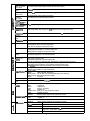
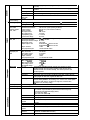
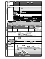
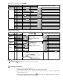
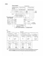
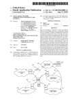
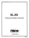
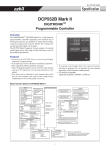
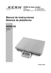
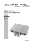
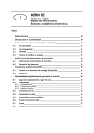
57-77-03-13 1/00 Page 1 of 12 DigitroniK DCP552 Digital Control Programmer Specification The DCP552 is a high-function programmer/ controller supporting two channels (up to 49 program patterns per channel) to which thermocouple, resistance temperature detector (RTD), DC voltage, DC current and other signals can be input. The DCP552 supports a memory card interface, 16 event outputs, 16 external switch inputs and a wide range of other functions as part of the standard specification. FEATURES ● Accuracy of ?0. 1 ‘AFS. Easy-to-view large display characters. Compact design ● Any input type can be selected by console key operation. ● Easy operation aided by guidance messages ● Up to 49 program patterns can be stored to each channel and up to 99 segments can be programmed to each pattern. ● ● ● ● Program patterns can be saved or loaded using the Smart Proximity Card (sold separately).SKM series ● The Smart Proximity Card uses highly durableSKM series and non-contact type cards Any event can be selected to each channel and set for the 16 event outputs, and code events comprising a combination of two or more points can be set. 16 external switch inputs allow the control of remote se/ection of program Nos. or operation on each channel separately or both channels simultaneously CE marking-compatible Applicable standards: EN61O 10-1, EN5008 1-2, EN50082-2 BASIC FUNCTION BLOCKS of DCP552 Input 1 • Thermocouple • Resistance temperature detector (RTD) • DC current • DC voltage • Thermocouple • Resistance temperature detector (RTD) • DC current • DC voltage • O2 sensor • Root extraction • Linearization table approximation • Input bias • Filter 12 external switch inputs RUN HOLD RESET ADV • • • • FAST RAMP-E AUTO/MANUAL AT • • • • • Output change limiter • Upper/lower limiter • Current-proportional • Voltage time-proportional • Open-collector time-proportional 16 event outputs • PID control • Auto-tuning • SP limit • SP bias • • • • • • • Time event PV SP Deviation MV Code Code w/timer • • • • PV SP Deviation MV • • • • • • • Modes Alarm Segment No. code Unique segments Program No. code PV rate-of-change O2 sensor error 1, 2 auxiliary outputs • PV2 channel selection 4 external switch inputs • Current-proportional • Voltage time-proportional • Open-collector time-proportional • Mode transition • Direct/reverse action • ON-OFF control • Program No. • CH1 operation cancel • CH2 operation cancel Output 1 • Output change limiter • Upper/lower limiter Output 2 *3 Input 2 • • • • Control operation block • Root extraction • Linearization table approximation • Input bias • Filter G.Soak cancel Direct/reverse action Autoload O2 sensor check RS-485/RS-232C communications I/O *1 *1 Key operation • Display selection • Display channel selection • Program No. • RUN/HOLD • RESET • ADV • • • • • • Loader communications I/O FAST AUTO/MANUAL AT Program setup Parameter setup Memory card operation Memory card Program • • • • • • *2 • Program • Parameter 2 channels x 49 patterns x 99 segments PID sets/output limiter sets Events • PV start G.Soak • Cycle PV shift • Pattern link Repeat Parameter • • • • • Variable parameter Event configuration PID parameter Setup Constant-value operation *1: Option according to Model No. *2: Sold separately *3: Thermocouple, RTD, DC current and DC voltage can be selected on models not supporting CP. Models supporting CP become O2 sensors. Memory card read/write + Smart Loader package *2 E m a o k Number of progrems 49 programs x 2 channels Number of segments 99 per program, total 2000 Segment setting system RAMP-X: Set by set points (SP) and time. RAMP-T: Set by set points (SP) and ramp (13) RAMP-E: Set by set points (SP) and ASP per external switch input 1 pulse Segment time 0 to 500 hours 0 minute, 0 to 500 minutes 0 second, 0.0 to 3000.0 seconds (time unit selectable) Segment ramp 1 to 10000 U/hour, 1 to 10000 U/minute, 1 to 10000 U/second (time unit selectable) Segment ASP 1 to 10000 U/l pulse Number of aubfunctions 4000 Sub-function action Events, PID set, output limiter set, G. Soak, PV shift, repeat Eventa (16) Set operating point corresponding to event type PID set No. Set 0 (continuation of previous segment), 1 to 9, A set (automatically switched) and ON-OFF control Output limiter aet Set 0 (continuation of previous segment), 1 to 9 G.Seek Set type (start/end points and overall) and G.Soak width 0 to 1000 U. PV shift -10000 to +10000 U Repeat Set return destination segment No. and repeat count. PV start Set type (rising/falling or both) for each program. Cycle Set cycle count for each program. Pattern link Set program No.O to 49 (0: no link) for each program. Tag Set 8 alphanumerics or symbols for each program. Baeic time accuracy +0.01 % (segment time setting = 0, with 0.1 second delay for each repeat and cycle) Input type Thermocouple, resistance temperature detector (RTD), DC voltage, DC current multi-range Sampling cycle 0.1 seconds Input bias current Thermocouple, DC voltage input: Max. ±1.3 uA (at peak value and reference conditions) 1 V or higher range: Max. -3 @ Input impedance DC current input: approx. 50 Cl (under operating conditions) Measuring current RTD input: Approx. 1 mA current flow from terminal A (under operating conditions) Influence of wiring resistance Thermocouple, DC voltage input: Thermocouple: 0.5 pvm DC voltage (max. 1 V range): 0.5 pV/Q DC voltage (5 V range): 3 pvm DC voltage (10 V range): 6 pVIQ Max. ~0.01 %FS/Q in wiring resistance range 0 to 10 Cl RTD input: Range of F01, F33, P01 and P33: +0.02 %FS/~ max. RTD input allowable wiring reslstance g a g (See pages 6, 7.) Ranges other than F01, F33, P01 and P33: 85 Q max. (including Zener barrier resistance. Note that site adjustment is required.) . Ranges of F01, F33, PO1 and P33: 10 Q max. (Zener barrier cannot be used.) ● Allowable parallel resistance Thermocouple disconnection detection allowable parallel resistance: 1 ML? min. Max. allowable Input Thermocouple, DC voltage input: -5 to+15V dc DC current input: 50 mA dc, 2.5V dc Burnout Detection selectable Over-range detection threshold 110%FS min.: Upscaled -10%FS max.: Downscaled (Note that F50 range is not downscaled.) Cold-junction compensation accuracy *0.5°C (under standard conditions) Cold- junction compensation system Internal/external (O”C only) compensation selectable Scaling -19999 to +20000 U (possible in case of linear input only. Inverse scaling possible. Decimal point position settable at any point) Square root extraction Possible. Dropout: 0.2 to 10.0% in case of DC current or DC voltage range PV equalizer (linearization table approximation) PV1: 9 segments (1 O points set) PV2: 9 segments (1 O points set) CP: 9 segments (1 O points set) Input bias -1000 to +1000 U variable Digital filter 0.0 to 120.0 seconds variable (0.0: filter OFF) 2 a s g c f.r e 3 al z c $ z w k E E ~ m o a 2 o = ; u = Number of inputs 16 Types of connectable outputs Dry contacts (relay contact) and open-collector (current sink to ground) Terminal voltage (open) 8.5 WO.5 V between common terminals (terminals 12, 40) and each input terminal (under operating Terminal current (short-circuit) Approx. 6 mA between each terminal (under operating conditions) Allowable contact resistance (dry contact) ON: 250 ohm max. (under operating conditions) OFF: 100 kohm min. (under operating conditions) Voltsge drop (at opan-collector ON) 2 V max. (under operating conditions) conditions) Leaksge current (at 0.1 mA max. (under operating conditions) open-collactor OFF) Aealgnmants (fixed) RUN, HOLD, RESET, ADV, program No., CH1 operation cancel, CH2 operation cancel Asslgnmants (variable) RAMP-E, FAST, AT, AUTO/MANUAL, G.Soak cancel, auto-load, 0, sensor check Input sampling cycle 0.1 seconds ON datectlon min. hold time 0.2 seconds (0.4 seconds for program No.) Upper display Green 5-digit, 7-segment LED This displays PV values in the basic display state. Item codes are displayed in the parameter setup. Lower display Orange 5-digit, 7-segment LED This displays SP and output % in the basic display state. Setting values are displayed in the parameter setup. Program No. display Green 2-digit, 7-segment LED This displays program No. in the basic display state. Segment No. displsy Green 2-digit, 7-segment LED This displays segment No. in the basic display state. Item Nos. are displayed in parameter setup, and alarm No. is displayed when alarm occurs. Message display This displays output graph, deviation graph, event state and tags in the basic display state. This displays reference messages in the parameter setup and program setup. This displays operation details and operation results of memory card operation. Profile display 7 orange LEDs Displays program pattern rise, soak and fall trends. Statua diaplaya 22 round LEDs Modes: Display details: Battery voltage: Status: RUN, HLD, MAN, PRG (green) PV, SP, OUT, TM, CYC, SYN, DEV (green), EG1, EG2 (red) BAT (red) (blinks at low voltage) AT (green) Operation keys 18 rubber keys Loader connector port 1 (dedicated cable with stereo miniplugs) Progrsm operation modaa READY: RUN: HOLD: FAST: END: READY FAST: Ready to run program (control stop/program No. selectable) Program run Program hold Program, fast-forward Program end Ready to run and fast-forward program AUTO: MANUAL: Automatic operation Manual operation (output can be controlled on console) READY: RUN: Ready to run program (control stop) Program run In $ : Constsnt-value operation modes AUTO: MANUAL PID control; 3 = : E Automatic operation Manual operation (output can be controlled on console) Proportional band (P) 0.0 to 1000.0’% (0.0: ON-OFF control) Resat time (1) 0 to 3600 seconds. 0 seconds: PD control Rste time (D) 0 to 1200 seconds. 0 seconds: PI control MV limit Lower limit: Upper limit: Manual reset 0.0 to 100.0% 6 3 -5.0 to upper limit Y. Lower limit to +105.0% PID controls Direct/reverse action switching Auxiliary output Nu mber of PID sets 16 sets for program operation (9 segment unique sets + 7 sets for automatic zone selection) PID set selection Segment designation/automatic zone seiection can be switched by program operation. MV change 0.1 to 110.0%/0.1 seconds Auto-tuning Automatic setting of PiD value by limit cycle system ON-OFF control differential 0 to 1000 U Possible Output types SP1, PV1, deviation 1, MV1, SP2, PV2, deviation 2, 0, sensor mV value Scaling Possible Current output (SG) CH1, CH2 auxiliary outputs CH1, CH2 Output current: Allowable load resistance: Output accuracy: Output resolution: Max. output current: Min. output current: Output updating cycle: Open terminai voitage: 4 to 20 mA dc 600 ohm max. (under operating conditions) &3.1 %FS max. (under standard conditions) 1 If 0000 21.6 mA dc 2.4 mA dc 0.1 seconds 25 V max. Voltage output (6D) CH1, CH2 Allowable load resistance: Load current adjustment: Variable open terminal voltage: OFF leakage current: Output response time: Output resolution: Time-proportional cycle: 600 Q max. (under operating conditions) 2 to 22 mA variable 25 V max. 100 PA max. At ON-OFF 600 Q load: 0.5 ms max. At OFF-ON 600 Q load: 0.5 ms max. 1/1000 1 to 240 seconds variabie Open-collector output (8D) CH1 CH2 External supply voltage: Max. load current OFF leakage current: ON residual voltage: Output resolution: Time-proportional cycle: 12 to 24 Vdc 100 mA/load 0.1 mA max. 2 V max. 1/1000 1 to 240 seconds variable Open-collector External supply voltage: Max. load current Max. common current: OFF leakage current: ON residual voltage 12 to 24V dc 70 mAlload 500 mA 0.1 mA max. 2 V max. Event types PV type PV, deviation, w/deviation standby, absoiute value deviation, w/ absoiul deviation standby, PV rate-of-change, SP, MV, G.Soak absolute valued w/G.Soak absolute value deviation standby, PV1 constant operation, PV2 constant operation Time type Time events, RAMP-E time monitor, segment time, program time Code type Code event, code event w/ timer, program No. binary code, segment No. binary code, program No. BCD code, segment No. BCD code Mode type Unique segment, RUN+HOLD+END+FAST, HOLD, READY+READY FAST, END G.Soak standby, MANUAL, AT executing, FAST+ READY FAST, console operation in progress, RUN, advance, all alarms, PV range alarm, controller alarm, 02 sensor error, low battery voltage Event hysteresis In case of PV type set, 0 to 1000 U Event ON delay 0.0 to 3000.0 can be set to four events Multidrop Network This controller is provided with only slave instrument functionality excep connected to ST221 (dedicated display device). 1 to 16 units max. (DIM) 1 to 31 units max. (CMA, SCM) RS-485 Data flow Half dupiex Synchronization Start-stop synchronization Transmission system Balanced (differential) Data iine Bit seriai Signal line 5 transmit/receive lines (3-wire connection also possible) Transmission speed 1200, 2400,4800, 9600 bps Transmission distance 500 m max. (totai) (300 m max. for MA500 DIM connection) Other Conforming to RS-485 interface specifications 4 RS-485 11 bits/character Char. bit count Format 1 start bit, even parity, 1 stop bI~ or 1 start bk, no parity, and 2 stop bits Data length 8 bits Isolation All inputs and outputs are completely isolated except external switch inputs. RS-485 communications can be performed by connecting to a computer equipped with an RS-485 interface. RS-232C Network 1:1 Connected, This controller is provided with only slave instrument functionality. Data flow Half duplex Synchronization Start-stop synchronization Transmission system Unbalanced type Data iine Bit seriai Si9nai iine 3 transmiVreceive iines I 1200, Tranamiaaion i Saaed Tranemiaaion distance 15 m max. Other Conforrnintr to RS-232C intertace .fmecifications Char. bit count 11 bits/character Format 1 start bit, even garitv, 1 stoD bit or 1 start bit, no Daritv. and 2 stoD bits \ Data length I 8 bits isoiation i 2400, 4800, 9600 bps Aii inputs and outputs are completely isoiated except externai switch inputs. Program, PiD, various parameters (SETUP, PARA, event) and other data can be saved and ioaded to and from memory card (sold seDarateiv). Function for copying DCP552 data to memory card. Save (SAVE) Load (LOAD) I Function for copying memory card data to DCP552. I Memory card (sold separately) Number of Progrems Battery Replacement Parameters Model No. Memory Type Size (bytes) SKMO08A RAM 7.00 K SKM018A RAM 14.50 K SKM064A RAM 61.75 K SKM256C RAM 251 K Max. 49 Possibie Event configuration data SKMO08E EEPROM 7.00 K Max. 10 Battery not required Constant-value operation data Max. 10 Not Dossibie SetuD data Max. 26 Not possibie Variable parameters Max. 49 Not possible PiD parameters reauired ● Number of bytes per program is 26 + (5x number of segments) + (5x number of sub-functions). ● Number of bytes per parameter Memory backup Memory Battery iife Setup data: 217 bytes (17+2x100) Variabie parameters: 257 bytes (17+2x120) PiD parameters+ constant-vaiue operation data: 565 bytes (17+2x2x8x16+2x2x9) Event configuration data: 209 . bytes (17+2x3x32) Battery backed up RAM Controiier power OFF: Approx. 5 years under standard conditions Controiier power ON: Approx. 10 years under standard conditions Rated power voita!re 100 to 240V ac, 50/60 Hz Power consumption 25 VA max. Power ON rush current ] 50A max. m c o = m o ~ [ Power ON operstian Reset time: 10 seconds max. (time untii normai operation is possibie under normai operating conditions) Aiiowebie transient powar ioss 20 ms max. (under operating conditions) Insulation resistance Min. 50 Mfl across power terminai 39 or 40 and FG terminal 52 or 53 (by 500V dc megger) Dieiectri;strength 1500V ac 50/60 Hz for 1 minute between power terminai and FG terminai Standard conditions Note) The primary side and secondary side capacities are joined inside the product. For this reason, when carrying out a withstand voltage test, disconnect the wiring of the grounded secondary side terminals (e.g. when grounding type thermocouple is used) from tha terminai. if the test is carried out with the wiring as it is, this might resuit in malfunction, Ambient temperature 23ti°C ~ a! c 8 Ambient humidity Rated power voitage 60k5%RH Power frequency 105V acfl % 50+1 l+z, Or 60*1 Vibration resistance 0 mls’ Shock resistance 0 mls’ M o u n t i n g angie - l+ Reference piane (verticai) *SO 5 Operating conditions Transport/storage conditions Ambisnt tempereturs range O to 50”C (ambient temperature at the bottom side of case when gang-mounted) Ambient humidity range 10 to 90%RH (condensation not allowed) Rated power voltage 100 to 240V ac Allowable power voltage 90 to 264V ac Power frequency 5&t2 Hz, or 60& Hz Vibration resistance 0 to 1.96 IT@z Shock resistance 0 to 9.80 nlk+z Mounting angle Reference plane (vertical) *1 0 degrees Ambient temperature range -20 to +71)”C Ambient humidity range 10 to 95%RH (condensation not ailowed) Vibration resistance O to 4.90 m/s2 (1 O to 60 Hz for 2 hours each in X, Y and Z directions) Shock resistance O to 490 m/s2 (3 times vertically) Peckege drop test Drop height: 60 cm (1 angle, 3 edges and 6 planes; free fall) Terminal ecrew M3.5 self-tapping screws Terminal screw tightening torque 0.76 to 0.98 N.m Masfdcese materials Mask MultiIon Case: MultiIon Masfdcase color Mask: Dark gray (Munsell 5Y3.5/1) Case: Light gray (Munsell 2.5Y7.5/l ) Inetalletion SDeciallv desianed mountino bracket I Approx. 1.5 kg Weight Item Model No. — Q’tv Item Model No. 1 61446141-001 Q’ty — Mounting bracket 81446044-001 1 set (2 p’ces) Soft dust-proof cover eet User’s Manual CP-UM-5017E 1 Lithium battery set 81448140-001 Approx. 200 g SKMO08A SKM016A SKM064A Approx. 30 g Unit Indlcsting label Memory csrd (RAM, battery replscament not possible) Table 1 Input Types and Ranges (selectable in setup) ● Thermocouple Input Type Symbol Input Range (FS) I Code ] Range No. ] 16 K46 K (CA) °C “F Accuracy (under standard conditions) -200.0 to +200.0 -300.0 to +400.0 +0.l%FS K (CA) K09 o 0.0 to 1200.0 0 to 2400 +O.l YoFS K (CA) K08 1 0.0 to 800.0 0 to 1600 Mll%FS K (CA) K04 2 0.0 to 400.0 0 to 750 ?O.l%FS E08 3 0.0 to 800.0 0 to 1800 %0.l%FS J (iC) J08 4 0.0 to 800.0 0.0 to 1600 M.19”FS T (CC) T44 -200.0 to +300.0 -300 to +700 M.l%FS M.3%FS between -200”C to -45°C B (PR30-6) B18 6 0.0 to 1800.0 0 to 3300 m.l%Fs *4.0”/’FS between 0 to260”C, MI. 15°/’FS between 260 to 800°C R (PR13) R16 7 0.0 to 1600.0 0 to 3100 &lYoFS S (PR1 O) S16 8 0.0 to 1600.0 0 to 3100 M. 1 %FS W (WRe5-26) W23 9 0.0 to 2300.0 0 to 4200 Mll%FS W (WRe5-26) W14 10 0.0 to 1400.0 0 to 2552 kO.l%FS PR40-20 D19 11 0.0 to 1900.0 0 to 3400 *0.2%FS N U13 12 0.0 to 1300.0 32 to 2372 *0.l%FS PLII yl 3 13 0.0 to 1300.0 32 to 2372 kO.l%FS Ni-Ni.Mo 213 14 0.0 to 1300.0 32 to 2372 kO.l%FS Golden iron chromel 206 15 E (CRC) – 5 0.0 to 300.0 K (K: Kelvin) 6 M3.4%FS tO.9”/!FS between 0 to 300”C, fl.5°/QFS between 300 to 800”C ● Resistance temperature detector (RTD) Input Type Input Range (FS) Accuracy (under standard conditions) Symbol Code Range No. °C ‘F JIS’89Pt100 F50 64 -200.0 to +500,0 -300.0 to +900.0 ~0.l%FS (IEC Pt100Q) JIS’89JPt100 F46 65 -200.0 to +200,0 -300.0 to +400.0 +0.l%FS F32 66 -100.0 to +150.0 -150.0 to +300.0 *0.l%FS F36 67 -50.0 to +200.0 -50.0 to +400,0 fO.l%FS F33 68 -40.0 to +60.0 -40.0 to +140.0 iO.15%FS FO1 69 0,0 to 100.0 0.0 to 200.0 +0. 15%FS F03 70 0.0 to 300.0 0.0 to 500.0 *O.l YoFS F05 71 0,0 to 500.0 0.0 to 900.0 *0.l%FS P50 96 -200.0 to +500.0 -300.0 to +900.0 fO,l%FS P46 97 -200.0 to +200,0 -300.0 to +400.0 fO.l%FS P32 98 -100.0 to +150,0 -150,0 to +300.0 *0.l%FS P36 99 -50.0 to +200.0 -50.0 to +400.0 +0.l%FS P33 100 -40.0 to +60.0 -40.0 to +140.0 tO.15%FS Pol 101 0.0 to 100.0 0.0 to 200.0 tO.15%FS P03 102 0.0 to 300.0 0.0 to 500,0 tO.l%FS P05 103 0,0 to 500.0 0.0 to 900,0 +0.l%FS ● DC current, DC voltage Input Type Svmbol mA (linear) mV (linear) mA (linear) V (linear) O2 sensor* Input Range (FS) I Code ~Ranae No. C01 48 4 to 20 mA Z51 52 2.4 to 20 mA MO1 49 Otol OmV L02 — 50 -1Oto+l OmV Accuracy (under standard conditions) Programmable range tO,l%FS -19999 to +20000 +O,l%FS tO.l YoFS (decimal point position can be changed) tO.l%FS 51 0 to 100mV 1 Col 128 4 to 20 mA Z51 — 134 2.4 to 20 mA 129 Otolv — 130 -1 to +1 V Vol — 131 lto5v iO.l%FS 132 0 to 5V tO,l%FS — 133 Otolov 10.l YoFS — 135 0 to 1250 mV I *0.15%FS Programmable range +0.15~oFS -19999 to +20000 +0.l%FS (decimal point position can be *0.l%FS changed) +0.l%FS *O,l%FS I When converted to mV value Carbon potential (CP value) indication range: 0.000 to 4.000%C (Note that PID control is calculated in input range 0.000 to 2.000% C.) 02 partial pressure (POZ) indication range: 0.000 to 1.500 x 10⁻²⁰ atm *. Any 02 sensor made by Marathon Monitors, Cambridge, Corning, AACC (Advanced Atmosphere Control Corporation), and Furnace Control can be used. . PV2 is fixed for the 0, sensor in the case of models supporting carbon potential, El Handling Precautions The unit of code Z06 is Kelvin (K). The PV lower limit alarm does not occur with codes F50 and P50. The number of digits past the decimal point for DC current and DC voltage is programmable within the range 0 to 4. The PV upper limit alarm is output by the 02 sensor when the voltage exceeds 1375 mV. The PV lower limit alarm, however, is not output. 7 MODEL SELECTION GUIDE Key # - I - II - III - IV - V Key # I Basic Key No. — DCP552 I E II III Number of PV inputs Carbon Potential IV V Option Specifications Additions Digital Programmable Controller (2-loop model) —— Universal Output I 2 Two Inputs o None 1 Oxygen Sensor Input for Carbon Potential 0 None 1 1 Auxiliary output 2 2 Auxiliary outputs, Communications 00 None EXTERNAL DIMENSIONS (Unit: mm) 144 185 15,5 3 1- 4-+ 137 9’ ,, ~ — oe— — .— ——— ~~ ~ ——— ( ( c F P r IU=F. JJ ‘1 PANEL CUTOUT (Unit: mm) 138+; 8 Input 9 +–w w+– 9+– 9+– . Current output CH1 control output (current output) 43 CH2 control output (current output) 44 45 + 46 + Load +– ‘d SSR . Open collector output CH 1 control output (voltage output) CH2 control output (current output) +– 44 43 12 to 24V dc Load 46 45 12 to 24V dc Load t? CH1 CH2 m ?3 PI 48 49 50 51 — . +–- +– Receiver Receiver 44 43 — + Load CH1 control output (voltage output) 10 — CH2 control output (voltage output) 45 46 + SSR WIRING PRECAUTIONS 1. Isolating Inputs and Outputs Inside the Controller commutators, phase angle control SCR, radio communications equipment, welding equipment, high-voltage ignition equipment. Solid lines ———— show isolated items. Dotted lines - - - - - - show non-isolated items. (1) PV input CH1 PV input CH2 Loader communications External switch input Communications Memory card input Digital circuit Control output CH1 Auxiliary output CH1 Control output CH2 Auxiliary output CH2 Event output 2. Noise Countermeasures for Instrument Power Supplies (1) Reducing noise Connect the DCP552 to a single-phase power supply for instruments, and take measures to prevent the influence of electrical noise. Fast-rising noise CR filters are effective in countering fast-rising noise. Recommended CR filter: Yamatake Corporation Model No. 81446365-001 (2) Noise with a high wave height Varisters are effective in countering noise with a high wave height. However, note that the varister may become short-circuited when trouble occurs. Pay attention to this when providing a varister on a controller. Recommended varister: Yamatake Corporation Model No. 81446366-001 (for 100 Vac) 81446367-001 (for 200 Vac) 4. Ground Use only the FG terminal 52 or 53 on the DCP552 for grounding. Do not ground across other terminals. When it is difficult to ground shielded cable, prepare a separate GND terminal plate (earth bar). Ground type: Ground cable: Cable length: (2) 100 PD[ 2 mm2 min. annealed-copper wire (AWG14) Max. 20 m When there is a lot of noise If there is a lot of electrical noise, we recommend inserting an insulating transformer in the power circuit and using a line filter. 5. Precautions During Wiring (1) After providing anti-noise measures, do not bundle primary and secondary power leads together, or pass them through the same piping or wiring duct. (2) Maintain a distance of at least 50 cm between I/O signal leads or communications leads and the power lead. Also, do not pass these leads through the same piping or wiring duct. 3. Noise Generating Sources and Countermeasures 6. Inspection After Wiring Generally, the following generate electrical noise: After wiring is completed, be sure to inspect and check the wiring state. Wrong wiring may cause controller malfunction or accidents. Relays and contacts, electromagnetic coils, solenoid valves, power lines (in particular, 90 Vac min.) induction loads, inverters, motor WARRANTY / REMEDY Honeywell warrants goods of its manufacture as being free of defective materials and faulty workmanship. Contact your local sales office for warranty information. If warranted goods are returned to Honeywell during the period of coverage, Honeywell will repair or replace without charge those items it finds defective. The foregoing is Buyer's sole remedy and is in lieu of all other warranties, expressed or implied, including those of merchantability and fitness for a particular purpose. Specifications may change without notice. The information we supply is believed to be accurate and reliable as of this printing. However, we assume no responsibility for its use. While we provide application assistance personally, through our literature and the Honeywell web site, it is up to the customer to determine the suitability of the product in the application. Sensing and Control Honeywell Inc. 11 West Spring Street Freeport, IL 61032 www.honeywell.com/sensing 57-77-03-13 0100 Printed in USA