1
E
m
a
o
k
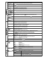
Number of progrems
49 programs x 2 channels
Number of segments
99 per program, total 2000
Segment setting
system
RAMP-X: Set by set points (SP) and time.
RAMP-T: Set by set points (SP) and ramp (13)
RAMP-E: Set by set points (SP) and ASP per external switch input 1 pulse
Segment time
0 to 500 hours 0 minute, 0 to 500 minutes 0 second, 0.0 to 3000.0 seconds (time unit selectable)
Segment ramp
1 to 10000 U/hour, 1 to 10000 U/minute, 1 to 10000 U/second (time unit selectable)
Segment ASP
1 to 10000 U/l pulse
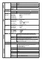
Number of aubfunctions
4000
Sub-function action
Events, PID set, output limiter set, G. Soak, PV shift, repeat
Eventa (16)
Set operating point corresponding to event type
PID set No.
Set 0 (continuation of previous segment), 1 to 9, A set (automatically switched) and ON-OFF control
Output limiter aet
Set 0 (continuation of previous segment), 1 to 9
G.Seek
Set type (start/end points and overall) and G.Soak width 0 to 1000 U.
PV shift
-10000 to +10000 U
Repeat
Set return destination segment No. and repeat count.
PV start
Set type (rising/falling or both) for each program.
Cycle
Set cycle count for each program.
Pattern link
Set program No.O to 49 (0: no link) for each program.
Tag
Set 8 alphanumerics or symbols for each program.
Baeic time accuracy
+0.01 % (segment time setting = 0, with 0.1 second delay for each repeat and cycle)
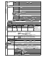
Input type
Thermocouple, resistance temperature detector (RTD), DC voltage, DC current multi-range
Sampling cycle
0.1 seconds
Input bias current
Thermocouple, DC voltage input: Max. ±1.3 uA (at peak value and reference conditions)
1 V or higher range: Max. -3 @
Input impedance
DC current input: approx. 50 Cl (under operating conditions)
Measuring current
RTD input: Approx. 1 mA current flow from terminal A (under operating conditions)
Influence of wiring
resistance
Thermocouple, DC voltage input: Thermocouple:
0.5 pvm
DC voltage (max. 1 V range): 0.5 pV/Q
DC voltage (5 V range):
3 pvm
DC voltage (10 V range):
6 pVIQ
Max. ~0.01 %FS/Q in wiring resistance range 0 to 10 Cl
RTD input:
Range of F01, F33, P01 and P33: +0.02 %FS/~ max.
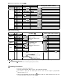
RTD input allowable wiring reslstance
g
a
g
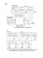
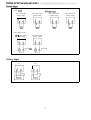
(See pages 6, 7.)
Ranges other than F01, F33, P01 and P33: 85 Q max.
(including Zener barrier resistance. Note that site adjustment is required.)
. Ranges of F01, F33, PO1 and P33: 10 Q max.
(Zener barrier cannot be used.)
●
Allowable parallel
resistance
Thermocouple disconnection detection allowable parallel resistance: 1 ML? min.
Max. allowable
Input
Thermocouple, DC voltage input: -5 to+15V dc
DC current input:
50 mA dc, 2.5V dc
Burnout
Detection selectable
Over-range
detection threshold
110%FS min.: Upscaled
-10%FS max.: Downscaled (Note that F50 range is not downscaled.)
Cold-junction
compensation
accuracy
*0.5°C (under standard conditions)
Cold- junction
compensation
system
Internal/external (O”C only) compensation selectable
Scaling
-19999 to +20000 U (possible in case of linear input only. Inverse scaling possible. Decimal point position
settable at any point)
Square root
extraction
Possible. Dropout: 0.2 to 10.0% in case of DC current or DC voltage range
PV equalizer
(linearization table
approximation)
PV1: 9 segments (1 O points set)
PV2: 9 segments (1 O points set)
CP: 9 segments (1 O points set)
Input bias
-1000 to +1000 U variable
Digital filter
0.0 to 120.0 seconds variable (0.0: filter OFF)
2