1
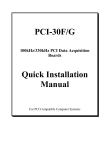
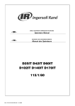
PC104-30FG Series
PCI PnP Analog Input Board
User’s Manual
Eagle Technology – Cape Town, South Africa
Copyright © 2002-2003
www.eagledaq.com
PC104-30FG User Manual
Analog Input Boards
Data Acquisition and Process Control
© Eagle Technology
31-35 Hout Street • Cape Town • South Africa
Phone +27 21 423 4943 • Fax +27 21 424 4637
Email [email protected]
Eagle Technology © Copyright 2003
i
PC104-30FG User Manual
Copyright
All rights reserved. No part of this publication may be reproduced, stored in a
retrieval system, or transmitted, in any form or any means, electronic,
mechanical, by photographing, recording, or otherwise without prior written
permission.
Copyright © Eagle Technology, South Africa
March 2003
Revision 1.0
Information furnished in this manual is believed to be accurate and reliable;
however no responsibility is assumed for its use, or any infringements of
patents or other rights of third parties, which may result from its use.
Trademarks and Logos in this manual are the property of their respective
owners.
Product Warranty
Eagle Technology, South Africa, warrants its products from defect in material
and workmanship from confirmed date of purchase for a period of one year if
the conditions listed below are met. The product warranty will call the Eagle
Technology Data Acquisition Device short as ETDAQD.
•
•
•
The warranty does not apply to an ETDAQD that has been previously
repaired, altered, extended by any other company or individual outside the
premises of Eagle Technology.
That a qualified person configure and install the ETDAQD, and damages
caused to a device during installation shall make the warranty void and
null.
The warranty will not apply to conditions where the ETDAQD has been
operated in a manner exceeding its specifications.
Eagle Technology, South Africa, does not take responsibility or liability of
consequential damages, project delays, damaging of equipment or capital
loss as a result of its products.
Eagle Technology, South Africa, holds the option and final decision to repair
or replace any ETDAQD. Proof of purchase must be supplied when
requesting a repair.
Eagle Technology © Copyright 2003
ii
PC104-30FG User Manual
TABLE OF CONTENTS
1
INTRODUCTION
1
Features
1
Key Specifications
1
Software Support
1
2
2
INSTALLATION
Package
2
Operating System Support
2
Hardware Installation
3
Software Installation
Windows 2000/XP
Resource Setup
Post installation
3
3
9
10
3
13
INTERCONNECTIONS
Pin Assignments
13
Signal Definitions
14
Analog Input
Single Ended Inputs
Differential Inputs
15
16
17
Analog Output
18
Digital Input/Output
18
Counter-Timer
18
4
19
PROGRAMMING GUIDE
EDR Enhanced API
19
Digital Inputs/Outputs
Reading the Digital Inputs
Writing to the Digital Outputs
20
20
20
Counters
Writing the initial counter value
21
21
Eagle Technology © Copyright 2003
iii
PC104-30FG User Manual
Reading a counter
Configuring a counter
Controlling the counter gate
21
22
22
Analog Output
Writing to a DAC channel
23
23
Analog Input
Reading a single voltage from a channel
Streaming Data
Configuring the ADC subsystem for scanning
Starting and Stopping the ADC process
Getting data from the driver buffer
Querying the ADC subsystem
24
24
25
26
28
29
30
5
31
CALIBRATION
A/D Calibration
Requirements
Equipment Required
Setting the Reference Voltage
Calibration Procedure
31
31
32
32
33
A/D Calibration Software
34
DAC0 to DAC3 Calibration
34
A.
35
CONFIGURATION CONSTANTS
Query Codes
35
Error Codes
36
Digital I/O Codes
36
B.
37
ORDERING INFORMATION
Eagle Technology © Copyright 2003
iv
PC104-30FG User Manual
Table of Figures
Figure 2-1 Step 1 .............................................................................................3
Figure 2-2 Step 2 .............................................................................................4
Figure 2-3 Step 3 .............................................................................................4
Figure 2-4 Step 4 .............................................................................................5
Figure 2-5 Step 5 .............................................................................................5
Figure 2-6 Step 6 .............................................................................................6
Figure 2-7 Step 7 .............................................................................................6
Figure 2-8 Step 8 .............................................................................................7
Figure 2-9 Step 9 .............................................................................................7
Figure 2-10 Step 10 .........................................................................................8
Figure 2-11 Step 11 .........................................................................................8
Figure 2-12 Device Manager..........................................................................11
Figure 2-13 EAGLE DAQ Dialog ....................................................................12
Figure 3-1 Single ended analog input ............................................................16
Figure 3-2 Differential Analog Inputs..............................................................17
Figure 4-A EDR Enhanced Design.................................................................19
Figure 5-1 A/D Calibration Connections.........................................................32
Eagle Technology © Copyright 2003
v
PC104-30FG User Manual
Table of Tables
Table 2-1 Operating System Support...............................................................2
Table 3-1 External Analog Connector – IDC-26M ..........................................13
Table 3-2 Internal DIO/CT Connector – IDC-40M ..........................................14
Table 3-3 Signal definitions ............................................................................14
Table 4-1 Counter Assignment.......................................................................21
Table 4-2 Counter Configuration ....................................................................22
Table 4-3 Gate Configuration .........................................................................22
Table D-D-1 Ordering Information..................................................................37
Eagle Technology © Copyright 2003
vi
PC104-30FG User Manual
1 Introduction
The PC104-30FG series PC104 bus architecture data acquisition boards.
They are available in two basic models, the G and F series. They can samples
at 100kHz or 330kHz respectively. Addition to analog input, they also have
analog output, digital input/output and counter-timer capabilities. For this
reason the PC104-30FG is an excellent all purpose data acquisition device
with extensive analog input capabilities.
Features
The PC104-30FG does have some very unique features and are short listed
below:
•
•
•
•
•
•
8/16 differential or 16/32 single-ended A/D inputs
330kHz or 100kHz sampling rate
Software controlled input ranges and gains
12bit Resolution
3 x 8-bit I/O ports
1 user counter-timers
Key Specifications
•
•
•
•
•
A/D resolution: 12-bits
D/A resolution: 12-bits
DIO width: 8-bits
CT width: 16-bits
A/D scan rate: 100kHz or 330kHz
Software Support
The PC104-30FG is supported by EDR Enhanced and comes with an
extensive range of examples. The software will help you to get your hardware
going very quickly. It also makes it easy to develop complicated control
applications quickly. All operating system drivers and utility are supplied on a
CD-Rom.
Eagle Technology © Copyright 2003
1
PC104-30FG User Manual
2 Installation
This chapter describes how to install and configure the PC104-30FG for the
first time. Minimal configuration is necessary; almost all settings are done
through software.
Package
PC104-30FG package will contain the following:
• PC104-30FG board
• EDR Enhanced Software Development Kit CD-Rom
Operating System Support
The PCI104-30FG series support the Windows NT and Windows Driver
Models (WDM) driver types. The operating systems are listed in the table
below.
Board Type
PC104-30FG
Revision
Revision 1
Operating Systems
Windows 2000/XP
Driver Type
WDM PnP
Table 2-1 Operating System Support
Eagle Technology © Copyright 2003
2
PC104-30FG User Manual
Hardware Installation
This section will describe how to install your PC104-30FG into your computer.
•
Switch off the computer and disconnect from power socket.
Failure to disconnect all power cables
can result in hazardous conditions, as
there may be dangerous voltage levels
present in externally connected
cables.
•
•
•
•
•
Remove the cover of the PC.
Insert bracket screw and ensure that the board sits firmly in the PC104
socket.
Replace the cover of the PC.
Reconnect all power cables and switch the power on.
The hardware installation is now completed.
Software Installation
Windows 2000/XP
Installing the Windows 2000/XP device driver is a very straightforward task.
The board does support plug and play so Windows needs to be told that a
new device was installed. The Add New Hardware Wizard will be used for this
task.
Click Start-> Settings-> Control Panel-> Add New/Remove Hardware.
Figure 2-1 Step 1
Eagle Technology © Copyright 2003
3
PC104-30FG User Manual
Select Add a device.
Figure 2-2 Step 2
Select Add a new device.
Figure 2-3 Step 3
Select No, I want to select the hardware from a list
Eagle Technology © Copyright 2003
4
PC104-30FG User Manual
Figure 2-4 Step 4
Select Other Device or Eagle Data Acquisition if it exists.
Figure 2-5 Step 5
Eagle Technology © Copyright 2003
5
PC104-30FG User Manual
Select Have Disk.
Figure 2-6 Step 6
Use the browse dialog to search for the file pc10430h.inf.
Figure 2-7 Step 7
Eagle Technology © Copyright 2003
6
PC104-30FG User Manual
Figure 2-8 Step 8
The next dialog will display the model name of the board you are trying
to install.
Figure 2-9 Step 9
Select the Next button.
Eagle Technology © Copyright 2003
7
PC104-30FG User Manual
Figure 2-10 Step 10
Select the Finish button to complete the installation.
Figure 2-11 Step 11
Eagle Technology © Copyright 2003
8
PC104-30FG User Manual
Resource Setup
After hardware installation you will have to setup the necessary resources for
the PC104-30FG.
Setup the interrupt and DMA channels. Base address setup as 700 HEX as
default.
Eagle Technology © Copyright 2003
9
PC104-30FG User Manual
DIP Switch Settings
Base Address
SW1
0H
On
20H
On
40H
On
60H
On
80H
On
…
…
…
…
300H
On
320H
On
…
…
…
…
700H
On
720H
On
…
…
…
…
1FA0H
Off
1FC0H
Off
1FE0H
Off
SW2
On
On
On
On
On
…
…
On
On
…
…
On
On
…
…
Off
Off
Off
SW3
On
On
On
On
On
…
…
On
On
…
…
Off
Off
…
…
Off
Off
Off
SW4
On
On
On
On
On
…
…
Off
Off
…
…
Off
Off
…
…
Off
Off
Off
SW5
On
On
On
On
On
…
…
Off
Off
…
…
Off
Off
…
…
Off
Off
Off
SW6
On
On
On
On
Off
…
…
On
On
…
…
On
On
…
…
Off
Off
Off
SW7
On
On
Off
Off
On
…
…
On
On
…
…
On
On
…
…
On
Off
Off
SW8
On
Off
On
Off
On
…
…
On
Off
…
…
On
Off
…
…
Off
On
Off
Post installation
When done with the driver installation the device manager can be open to
make sure the installation was a success.
•
•
First make sure that the driver is working properly by opening the
Device Manager.
Check under the Eagle Data Acquisition list if your board is listed and
working properly. The picture below shows a typical board that is
installed.
Eagle Technology © Copyright 2003
10
PC104-30FG User Manual
Figure 2-12 Device Manager
•
•
•
•
Clearly you can see that the PCI device is listed and working properly.
Now the first part of your installation has been completed and ready to
install the EDR Enhanced Software Development Kit.
Run edreapi.exe found on the Eagle CD-Rom and follow the on screen
instructions
Further open the control panel and then the EagleDAQ folder. This
dialog should list all installed hardware. Verify your board’s properties
on this dialog. See picture below
Eagle Technology © Copyright 2003
11
PC104-30FG User Manual
Figure 2-13 EAGLE DAQ Dialog
Eagle Technology © Copyright 2003
12
PC104-30FG User Manual
3 Interconnections
The PC104-30FG is designed so that there is a connector for analog signals
and digital signals.
Pin Assignments
The table below shows the pin assignments for the PCI30FG.
Pin
1
3
5
7
9
11
13
15
17
19
21
23
25
Name
CH1
CH3
CH5
CH7
CH9
CH11
CH13
CH15
AGND
SENS0
SENS1
SENS2
SENS3
Pin
2
4
6
8
10
12
14
16
18
20
22
24
26
Name
CH0
CH2
CH4
CH6
CH8
CH10
CH12
CH14
AGND
DAC0
DAC1
DAC2
DAC3
Table 3-1 External Analog Connector – IDC-26M
Eagle Technology © Copyright 2003
13
PC104-30FG User Manual
Pin
1
3
5
7
9
11
13
15
17
19
21
23
25
27
29
31
33
35
37
39
Name
PA1
PA3
PA5
PA7
PB1
PB3
PB5
PB7
PC1
PC3
PC4
PC7
DGND
GATE2
OUT2
OUT1
CLK2
EXT_TRIG
EXT_CLK
+5V
Pin
2
4
6
8
10
12
14
16
18
20
22
24
26
28
30
32
34
36
38
40
Name
PA0
PA2
PA4
PA6
PB0
PB2
PB4
PB6
PC0
PC2
PC4
PC6
DGND
CLK0
GATE1
DGND
DGND
DGND
DGND
DGND
Table 3-2 Internal DIO/CT Connector – IDC-40M
Signal Definitions
This sections deal with all the signals abbreviations.
Signal
CH0-15
DAC0-3
SENSE0-3
PA0-7
PB0-7
PC0-7
GATE1
CLK0
OUT1
GATE2
CLK2
OUT2
EXT_TRIG
EXT_CLK
Description
Analog input channel
Analog output channel
Sensing line for analog output channel
Port A on PPI
Port B on PPI
Port C on PPI
Internal counter gate
Internal counter clock input
Internal clock output
User counter 0 gate
User counter 0 input
User counter 0 output
A/D external trigger
A/D external clock
Table 3-3 Signal definitions
Eagle Technology © Copyright 2003
14
PC104-30FG User Manual
Analog Input
The following three aspects of A/D operation can be configured:
• A/D input mode (single ended or differential)
• A/D voltage range
• A/D clock/trigger
A/D Input Mode
The PC104-30F, FA, G and GA models can provide either 16 single ended or
eight differential inputs. The use of differential inputs is recommended in
environments with high levels of electrical noise, when using long lines to
connect the analogue inputs, or for any input operating at a gain of greater than
10. Default power-up configuration is for single ended inputs.
A/D Voltage Range Setting
On the G and GA models you can switch between ±5V and 0V to 10V. LK1 must be
used to achieve the ±10V range (see board silk screen for jumper settings for the G
and GA models only). On the F and FA models, the range can be switched between
±5V and ±10V from software.
On the PC104-30 F/G board, you can refer to the text written on the silkscreen layer with regard to jumper settings.
CHANGING JUMPER LK1 TO THE 20
V POSITION DOES NOT ENABLE
YOU TO SELECT UNIPOLAR RANGE
0 TO 10 V.
Note that the default range setting is -5 to +5V.
Eagle Technology © Copyright 2003
15
PC104-30FG User Manual
Single Ended Inputs
With single ended inputs, connections share a common low reference that is
connected to analog ground. See figure below.
The advantage of such a connection is that you have a maximum number of
inputs. Its major disadvantage is the loss of common mode rejection
obtainable from differential mode. Single ended inputs are very sensitive to
noise lead lengths should be kept as short as possible.
CH0
V0
V15
CH15
AGND
Figure 3-1 Single ended analog input
Eagle Technology © Copyright 2003
16
PC104-30FG User Manual
Differential Inputs
In differential input mode two multiplexer switches per channel are used. The
A/D converter measures the difference in potential between the two channels.
Channels are paired to form a single differential input. Channel 0 and channel
8 is used as channel 0, channels 1 and 9 etc. To connect see diagram below.
It is also very important to know that each return connection must be
referenced to analog ground.
CH0
CH0 RET
V0
V7
CH7
CH7 RET
AGND
Figure 3-2 Differential Analog Inputs
In differential mode, all signal inputs to
the PCI30FG must be referred to ground.
This can be done by connecting a 1 to 10
kΣ
Σ resistor from the low end of each input
to ground.
Eagle Technology © Copyright 2003
17
PC104-30FG User Manual
Analog Output
The analog outputs come with sense lines and it is important to make sure
that they are connected to the correct channel. If left unconnected the output
will simple float at +10V or –10V. The analog output range is ±10V and is fully
software configurable. The EDR Enhanced driver support auto ranging and
will always select the range with the best possible resolution. For normal
operation simply connect SENSE0 to DAC0.
OVERLOADING ANY DIGITAL I/O LINE
WILL CAUSE SERIOUS DAMAGE TO THE
DIGITAL I/O CHIP. OPERATING OUTSIDE
THE TTL VOLTAGE RANGE WILL CAUSE
PERMANENT DAMAGE TO THE DIGITAL
I/O CONTROL CIRCUIT.
Digital Input/Output
The PCI30FG has got 3x8-bit digital I/O ports that are fully configurable as
inputs or outputs. The digital I/O uses a chip that is fully compatible with the
Intel 8255 programmable peripheral interface. Make sure not to overload the
PPI because it will cause serious damage and will need to be repaired.
Counter-Timer
There are three counter-timers on the PC104-30FG of which one are available
for the user. Two are used for A/D timing. The timers are compatible with the
Intel 8254 counter-timer device. The 8254 counter-timer datasheets can be
used as reference for configuring the counter-timer sub-system.
Eagle Technology © Copyright 2003
18
PC104-30FG User Manual
4 Programming Guide
The PC104-30FG is supplied with a complete software development kit. EDR
Enhanced (EDRE SDK) comes with a common application program interface
(API). The API also serves as a hardware abstraction layer (HAL) between the
control application and the hardware. The EDRE API make it possible to write
one application that can be used on all hardware with common sub-systems.
EDR Enhanced API
The EDR Enhanced SDK comes with both ActiveX controls and a Windows
DLL API. Examples are provided in many different languages and serve as
tutorials. EDRE is also supplied with a software manual and user’s guide.
The EDRE API hides the complexity of the hardware and makes it really easy
to program the PC104-30FG. It has got functions for each basic sub-system
and is really easy to learn.
Figure 4-A EDR Enhanced Design
Eagle Technology © Copyright 2003
19
PC104-30FG User Manual
Digital Inputs/Outputs
The PC104-30FG has 24 digital I/O lines, configured as 3 x 8-bit ports. The
EDRE API supports auto direction configuration. By writing to or reading from
a port, it is automatically configured as an output or input. A port is defined as
a collection of simultaneous configurable entities. Thus in the case of the
PC104-30FG each port is only 8-bits wide.
Reading the Digital Inputs
A single call is necessary to read a digital I/O port.
API-CALL
Long EDRE_DioRead(ulng Sn, ulng Port, ulng *Value)
The serial number, port, and a pointer to variable to hold the result must be
passed by the calling function. A return code will indicate if any errors
occurred.
ACTIVEX CALL
Long EDREDioX.Read(long Port)
Only the port-number needs to be passed and the returned value will either
hold an error or the value read. If the value is negative an error did occur.
Writing to the Digital Outputs
A single call is necessary to write to a digital I/O port.
API-CALL
Long EDRE_DioWrite(ulng Sn, ulng Port, ulng Value)
The serial number, port, and a value must be passed by the calling function. A
return code will indicate if any errors occurred.
ACTIVEX CALL
Long EDREDioX.Write(long Por, ulng Value)
The port number and value to be written needs to be passed and the returned
value holds an error or the value read. If the value is negative an error did
occur.
Eagle Technology © Copyright 2003
20
PC104-30FG User Manual
Counters
The counter sub-system is supported by functions to Write, Read and
Configure. There are 1 counters that are available to the user and are
compatible with the industry standard 8254 counter-timer. The table below
shows all counters and their assigned function on the board. Please note that
only some are available for the user. The 8254 datasheet has more
information on the counter-timer modes.
Counter
0
Software Assigned Number
0
Description
User Counter 0
Table 4-1 Counter Assignment
Writing the initial counter value
A single call is necessary to write a counter’s initial load value.
API-CALL
Long EDRE_CTWrite(ulng Sn, ulng Ct, ulng Value)
The serial number, counter-number, and a value must be passed by the
calling function. A return code will indicate if any errors occurred.
ACTIVEX CALL
Long EDRECTX.Write(long Port, ulng Value)
The port number and value to be written needs to be passed and the returned
value holds an error or the value read. If the value is negative an error did
occur.
Reading a counter
A single call is necessary to read a counter’s current value.
API-CALL
Long EDRE_CTRead(ulng Sn, ulng Ct, pulng Value)
The serial number, counter-number, and a pointer must be passed by the
calling function. A return code will indicate if any errors occurred. The value
buffer will hold the value read from the counter.
ACTIVEX CALL
Long EDRECTX.Read(long Port)
The port number needs to be passed. The returned value will either hold the
error code or the value read from the counter. If negative it means an error
occurred, otherwise it is the value read from the counter.
Eagle Technology © Copyright 2003
21
PC104-30FG User Manual
Configuring a counter
A single call is necessary to configure a counter.
API-CALL
Long EDRE_CTConfig(ulng Sn, ulng Ct, ulng Mode, ulng Type, ulng ClkSrc, ulng
GateSrc)
The serial number, counter-number, mode, type, clock source and gate
source is needed to specify a counter’s configuration. A return code will
indicate if any errors occurred.
ACTIVEX CALL
Long EDRECTX.Configure(long ct, long mode, long type, ulng source, ulng gate)
The counter-number, mode, type, clock source and gate source is needed to
specify a counter’s configuration. A return code will indicate if any errors
occurred.
Only the counter mode parameter is used by the PC104-30FG. The table
below shows the options for each parameter.
Parameter
Sn
Ct
Mode
Type
Source
Gate
Description
Serial Number
Counter Number:
0 : User Counter 0
8254 Counter Mode. See 8254 datasheet for details
0 : Binary Counting (16-bits)
1 : Binary Coded Decimal (BCD)
0 : Internal (8MHz)
1 : External (External connector)
0: Internal (Softgate)
1: External
Table 4-2 Counter Configuration
Controlling the counter gate
A single call is necessary to control a counter’s gate.
API-CALL
Long EDRE_CTSoftGate(ulng Sn, ulng Ct, ulng Gate)
The serial number, counter-number and gate are needed to control a
counter’s gate. A return code will indicate if any errors occurred.
ACTIVEX CALL
Long EDRECTX.SoftGate(ulng Ct, ulng Gate)
The counter-number and mode is needed to control a counter’s gate. A return
code will indicate if any errors occurred.
These values are acceptable as a gate source.
Value
0
1
Description
Gate disabled
Gate enabled
Table 4-3 Gate Configuration
Eagle Technology © Copyright 2003
22
PC104-30FG User Manual
Analog Output
The PC104-30FG-A version has 4 x 12-bit DAC channels that support single
write.
Writing to a DAC channel
A single call is necessary to set a voltage on a DAC channel.
API-CALL
Long EDRE_DAWrite (ulng Sn, ulng Channel, long uVoltage)
The serial number, DAC channel and micro-voltage is needed to set a DAC
channel’s voltage. A return code will indicate if any errors occurred.
ACTIVEX CALL
Long EDREDAX.Write (long Channel, long uVoltage)
The DAC channel and micro-voltage is needed to set a DAC channel’s
voltage. A return code will indicate if any errors occurred.
Eagle Technology © Copyright 2003
23
PC104-30FG User Manual
Analog Input
Analog input is when a voltage is read from a specific A/D channel or when
A/D channels are scanned in a specific sequence at a fixed rate.
Reading a single voltage from a channel
To read a single ADC channel you need to know the voltage range and gain.
API-CALL
Long EDRE_ADSingle (ulng Sn, ulng Channel, ulng Gain, ulng Range, plong uVoltage)
Parameter
Sn
Channel
Gain
Type
Unsigned long
Unsigned long
Unsigned long
Range
Unsigned long
uVoltage
Return
Pointer to a long
Long
Description
Board’s serial number
ADC Channel
0: Gain x 1
1: Gain x 10
2: Gain x 100
3: Gain x 1000
0: -5V to +5V, Single Ended
1: 0 to +10V, Single Ended
2: -10V to +10V, Single Ended
3: -5V to +5V, Differential
4: 0 to +10V, Differential
5: -10V to +10V, Differential
Voltage read from channel
Error Code
ACTIVEX CALL
Long EDREADX.SingleRead (long Channel)
Parameter
Channel
Return
Long
Long
Type
Description
ADC Channel
Voltage returned from channel.
Make sure to set the Gain and Range properties of the ADC ActiveX control.
This will in turn set the range and gain when reading the ADC channel.
Eagle Technology © Copyright 2003
24
PC104-30FG User Manual
Streaming Data
You must first setup the A/D sub-system A/D channels can be scanned. The
most important part is the channel and gain list. This tells the hardware in
which order to scan the channels and what gain to use. Other settings include
scanning frequency, voltage range, trigger source and mode.
Dual channel DMA is used when streaming data. Please note that each DMA
channel is 32K bytes, thus data will be updated in blocks of 16384 samples.
If you are scanning at a very slow speed it might take a while before any data
get be read from the driver buffer.
It is also important to understand the scanning mode. Normal mode means
the channels will be scanned one by one according to the channel list at the
specified frequency.
Eagle Technology © Copyright 2003
25
PC104-30FG User Manual
Configuring the ADC subsystem for scanning
This is the most complicated part of configuring the PC104-30FG for auto
scanning. Make sure that you use the correct format when applying the
channel list configuration. There are many loopholes and care should be
taken when implementing code to configure the PC104-30FG.
The channels list size should always consist of 2 or more channel, but not
more then 16. If you only want to read one channel, the same channel should
be placed in the channels list twice.
API-CALL
Long EDRE_ADConfig (ulng Sn, pulng Freq, ulng ClkSrc, ulng Burst, ulng Range,
pulng ChanList, pulng GainList, ulng ListSize)
The following parameters must be specified when configuring the ADC subsystem.
Parameter
Sn
Freq
ClkSrc
Burst
Range
ChanList
GainList
ListSize
Type
Unsigned
long
Pointer to
an unsigned
long
Unsigned
long
Unsigned
long
Unsigned
long
Pointer to
an unsigned
long
Pointer to
an unsigned
long
Unsigned
long
Description
Board’s serial number.
Sampling frequency. The actual sampling frequency will be returned with this
parameter.
0: Internal clock to A/D clock trigger and to external trigger.
1: External trigger disconnected, internal clock to A/D clock/trigger.
2: External trigger to A/D clock/trigger, internal clock disconnected.
3: External trigger to gate 1, internal clock to A/D clock/trigger.
0: Normal Mode
1: Burst Mode
0: -5V to +5V, Single Ended
1: 0 to +10V, Single Ended
2: -10V to +10V, Single Ended
3: -5V to +5V, Differential
4: 0 to +10V, Differential
5: -10V to +10V, Differential
This is an array of unsigned longs that contains the channels to be sampled when
scanning the ADC sub-system. The max size of the channel list is 16
This is an array of unsigned longs that contains the gains of channels to be
sampled when scanning the ADC sub-system.
This parameter determines the length the two previous arrays. This is also the
depth of the channel list that is programmed to the board.
Eagle Technology © Copyright 2003
26
PC104-30FG User Manual
ACTIVEX CALL
Long EDREADX.Configure (plong Channels, plong Gains, long ListSize)
Parameter Type
Description
Channels
Pointer to
This is an array of unsigned longs that contains the channels to be sampled when
an unsigned scanning the ADC sub-system. The max size of the channel list is 16
long
Gains
Pointer to
This is an array of unsigned longs that contains the gains of channels to be
an unsigned sampled when scanning the ADC sub-system.
long
ListSize
Unsigned
This parameter determines the length the two previous arrays. This is also the
long
depth of the channel list that is programmed to the board.
The Frequency and ClockSource ADC ActiveX control must be setup
before calling the configure function.
EDREADX.Frequency
Frequency
The ADC sampling frequency
WARNING!!
In normal sampling mode
channels are sampled sequentially
according to the given channels
list. The time spacing between
each channel is the same as the
frequency in normal mode. The
maximum frequency is the same
as the maximum speed of the
board.
In burst mode the all channels in
the channel list is converted as
fast as possible (depends on the
A/D converter speed) every
period. The period is the same as
the sampling frequency. The
maximum sampling frequency is
the maximum frequency of the
board divided by the number of
channels in the channel list.
Frequency Example:
Normal Mode
Frequency = 100 000 Hz
Channel List Length = 10
Time = 10 uS
Time between channels = 10 uS
Eagle Technology © Copyright 2003
Burst Mode
Max of Board = 100 000 Hz
Frequency = 20 000 Hz
Channel List Length = 10
Max Frequency = 2 000 Hz
Time = 500 uS
Time between channels = 10 uS (ADC Rating)
Time between sets = 50 uS
27
PC104-30FG User Manual
EDREADX.ClockSource
ClockSource
0: Internal clock to A/D clock trigger and to external trigger.
1: External trigger disconnected, internal clock to A/D clock/trigger.
2: External trigger to A/D clock/trigger, internal clock disconnected.
3: External trigger to gate 1, internal clock to A/D clock/trigger.
Starting and Stopping the ADC process
A single call is necessary to start or stop the ADC process
API-CALL
Long EDRE_ADStart (ulng Sn)
Parameter
Sn
Return
Type
Unsigned long
Long
Description
Board’s serial number
Error Code
ACTIVEX CALL
Long EDREADX.Start ()
Parameter
Return
Long
Type
Description
Error Code
API-CALL
Long EDRE_ADStop (ulng Sn)
Parameter
Sn
Return
Type
Unsigned long
Long
Description
Board’s serial number
Error Code
ACTIVEX CALL
Long EDREADX.Stop ()
Parameter
Return
Long
Type
Description
Error Code
Eagle Technology © Copyright 2003
28
PC104-30FG User Manual
Getting data from the driver buffer
A single call is necessary copy data from the driver buffer to the user buffer.
API-CALL
Long EDRE_ADGetData (ulng Sn, plong Buf, pulng BufSize)
Parameter
Sn
Buf
BufSize
Return
Type
Unsigned long
Pointer to a long
buffer.
Pointer to an
unsigned long
Long
Description
Board’s serial number
Buffer to copy micro voltages too.
Size of buffer must be passed or number of
samples requested. The returned value will
indicate the number of actual samples copied
to the buffer.
Error Code
ACTIVEX CALL
Long EDREADX.GetData (plong Buffer, plong Size)
Parameter
Buf
BufSize
Type
Pointer to a long
buffer.
Pointer to a long
Return
Long
Description
Buffer to copy micro voltages too.
Size of buffer must be passed or number of
samples requested. The returned value will
indicate the number of actual samples copied
to the buffer.
Error Code
Eagle Technology © Copyright 2003
29
PC104-30FG User Manual
Querying the ADC subsystem
The driver can be queried to check the status of the ADC subsystem. The
number of unread samples is one example.
API-CALL
Long EDRE_Query (ulng Sn, ulng QueryCode, ulng Param)
Parameter
Sn
QueryCode
Type
Unsigned long
Unsigned long
Param
Return
Unsigned long
Long
Description
Board’s serial number
Query code. See appendix
Example:
ADUNREAD: This will tell you the number of
available samples.
ADBUSY: Is the ADC subsystem busy?
Extra parameter.
Returned query code
ACTIVEX CALL
Long EDREADX.GetUnread ()
Parameter
Return
Long
Type
Description
Number of samples available in the driver.
This function automatically queries the ADC driver buffer for the number of
available samples.
Eagle Technology © Copyright 2003
30
PC104-30FG User Manual
5 Calibration
This chapter contains information to calibrate the A/D and D/A sub-systems of
the PC104-30FG. The PC104-30FG is calibrated during the manufacturing
test and therefore does not require recalibration under normal conditions.
However under extreme conditions or to optimize accuracy, the board needs
to be recalibrated.
Allow the host PC and the board to warm up
for at least one hour before calibration.
A/D Calibration
Requirements
•
•
•
Calibration is done on channel 1. The recommended connector wiring is
shown in Figure 5-1.
Calibration is performed with the board configured into its intended operating
mode.
All cables should be as short as possible. Note that screened cable is preferable
in order to minimize noise interference.
Eagle Technology © Copyright 2003
31
PC104-30FG User Manual
Figure 5-1 A/D Calibration Connections
Equipment Required
•
•
Precision voltage source. Range +10V to -10V, with an absolute accuracy
better than 0.005%, resolution 100 nV or better.
Precision digital multimeter with ±10V range, absolute accuracy better than
0.0005%, resolution 100 nV or better.
Setting the Reference Voltage
Before calibrating the A/D, the reference voltages must be set properly. This is
normally done during manufacturing, but if the voltage does not match, re-calibrate as
follows:
+10V
Connect the multimeter to analogue ground and U16 Pin 1 or C24 +ve Side (Indicated
on the component by a line). The voltage reading should be +10.0000V. If the voltage
is out of specification, adjust VR4.
Another method is to set DACs to ±10V output. Set DAC output to +10V using
Waveview. Connect SENSE0 [Pin 19 of AD-CON Connector] to DAC0 [Pin 20 of
AD-CON Connector]. Measure the output voltage on the output of DAC0 (ie: Pin 19
of IDC26 Male Header [AD-CON]). Adjust VR4 until a voltage of 9.995V is reached.
Eagle Technology © Copyright 2003
32
PC104-30FG User Manual
Calibration Procedure
Run the CAL30FG.exe program installed in the PC104-30 directory.
A/D Calibration for the PC104-30G/PC104-30GA Boards
Bipolar Mode
a) Adjust A/D for maximum gain (ie. 1000) and apply 0.00mV to Channel
1 (all other channels must be grounded to AGND). Adjust VR1 (PC10430FG Rev1B), the instrumentation amplifier offset pot, for output 800H.
b) . Set A/D for a gain of 1 and apply (-FS+2LSB) to channel 1 (ie. 4.9988V for ±5V or -9.9976V for ±10V). Adjust VR2 (PC104-30FG
Rev1c), bipolar A/D offset, for an output code which flickers between 000H
and 001H.
c) Set A/D for a gain of 1 and apply (+FS-3/2LSB) to channel 1 (ie.
+4.9963V for ±5V range or +9.9927V for ±10V). Adjust VR5 (PC10430FG Rev1c),gain pot, for an output code which flickers between FFEH and
FFFH.
d) . Repeat the above steps until no further adjustment is required.
Monopolar Mode
a) Adjust A/D for maximum gain (ie. 1000) and apply 0.00mV to Channel
1 (all other channels must be grounded to AGND). Adjust VR1 (PC10430FG Rev1B), the instrumentation amplifier offset pot, for output code 000H.
b) Set A/D for a gain of 1 and apply (FS+½LSB) to channel 1 (ie. for 0 to
10V range it should be +1.22mV). Adjust VR3 (PC104-30FG Rev1B),
A/D offset, for an output code which flickers between 000H and 001H.
c) Set A/D for a gain of 1 and apply (+FS-3/2LSB) to channel 1 (ie.
+9.9963V). Adjust VR6 (PC104-30FG Rev1B),gain pot, for an output
code which flickers between FFEH and FFFH.
d) Repeat the above steps until no further adjustment is required.
A/D Calibration for the PC104-30F/PC104-30FA Boards
Bipolar Mode (±5V)
a) Adjust A/D for maximum gain (ie. 1000) and apply 0.00mV to Channel 1 (all
other channels must be grounded to AGND). Adjust VR1 (PC104-30FG
Rev1B), the instrumentation amplifier offset pot, for output code 800H.
b) Set A/D for a gain of 1 and apply (+FS-3/2LSB) to channel 1 (ie. +4.9963V).
Adjust VR7 (PC104-30FG Rev1B), gain pot, for an output code which flickers
between FFEH and FFFH.
c) Set A/D for a gain of 1 and apply (-FS+½LSB) to channel 1 (ie. -4.9988V).
Adjust VR3 (PC104-30FG Rev1B), bipolar A/D offset, for an output code
which flickers between 000H and 001H.
d) Repeat the above steps until no further adjustment is required. Note that steps
2 and 3 above are inter-related, and it therefore requires some expertise to
enable ± Full Scale Convergence.
Eagle Technology © Copyright 2003
33
PC104-30FG User Manual
Bipolar Mode (±10V)
a) Adjust A/D for maximum gain (ie. 1000) and apply 0.00mV to Channel 1 (all
other channels must be grounded to AGND). Adjust VR1 (PC104-30FG
Rev1B), the instrumentation amplifier offset pot, for output code 800H.
b) Set A/D for a gain of 1 and apply (+FS-3/2 LSB) to channel 1 (ie. +9.9927V).
Adjust VR8 (PC104-30FG Rev1B), gain pot, for an output code which flickers
between FFEH and FFFH.
c) Set A/D for a gain of 1 and apply (-FS+½LSB) to channel 1 (ie. -9.9976V).
Adjust VR9 (PC104-30FG Rev1B), bipolar A/D offset, for an output code
which flickers between 000H and 001H.
d) Repeat the above steps until no further adjustment is required. Note
that steps 2 and 3 above are inter-related, and it therefore requires
some expertise to enable ± Full Scale Convergence.
A/D Calibration Software
The program CAL30FG.EXE, supplied on the distribution disk, automates the above
procedure. Note that for correct operation, the set-up information supplied in the first
menu must be correct.
DAC0 to DAC3 Calibration
In general, you do not need to calibrate the DACs at all, because it has already been
done when adjusting the reference voltages (ie. usually during manufacturing).
However, if you require a different full scale (+10 down to +8V) output on these
DACs, proceed as follows:
• Run the CAL30FG.exe program from the EDR sub-directory.
• Select DAC calibration. Alternatively, you can run Waveview and set DAC0 (with
SENSE0 shorted to DAC0) to maximum full scale (ie. 10V in WaveView).
• Connect the multimeter to the output of DAC0 (with SENSE0 shorted to DAC0)
and analogue ground.
• Adjust the reference pot VR4 (PC104-30FG Rev 1B) until you obtain the required
voltage output.
Eagle Technology © Copyright 2003
34
PC104-30FG User Manual
A. Configuration Constants
Query Codes
Name
APIMAJOR
APIMINOR
APIBUILD
APIOS
APINUMDEV
BRDTYPE
BRDREV
BRDYEAR
BRDMONTH
BRDDAY
BRDSERIALNO
DRVMAJOR
DRVMINOR
DRVBUILD
ADNUMCHAN
ADNUMSH
ADMAXFREQ
ADBUSY
ADFIFOSIZE
ADFIFOOVER
ADBUFFSIZE
ADBUFFOVER
ADBUFFALLOC
ADUNREAD
ADEXTCLK
ADEXTTRIG
ADBURST
ADRANGE
DANUMCHAN
D3AMAXFREQ
DABUSY
DAFIFOSZ
CTNUM
CTBUSY
DIONUMPORT
DIOQRYPORT
DIOPORTWIDTH
INTNUMSRC
Value
1
2
3
4
5
10
11
12
13
14
15
20
21
22
100
101
102
103
104
105
106
107
108
109
110
111
112
113
200
201
202
203
300
301
400
401
402
500
Eagle Technology © Copyright 2003
Description
Query EDRE API major version number.
Query EDRE API minor version number.
Query EDRE API build version number.
Query EDRE API OS type.
Query number of devices installed.
Query a board’s type.
Query a board’s revision.
Query a board’s manufactured year.
Query a board’s manufactured month.
Query a board’s manufactured day.
Query a board’s serial number.
Query a driver’s major version number.
Query a driver’s minor version number.
Query a driver’s build version number.
Query number of ADC channel.
Query number of samples-and-hold channels.
Query maximum sampling frequency.
Check if ADC system is busy.
Get ADC hardware FIFO size.
Check for FIFO overrun condition.
Check software buffer size.
Check for circular buffer overrun.
Check if software buffer is allocated.
Get number of samples available.
Get status of external clock line – PCI30FG.
Get status of external trigger line – PCI30FG.
Check if burst mode is enabled.
Get ADC range.
Query number of DAC channels.
Query maximum DAC output frequency.
Check if DAC system is busy.
Get DAC FIFO size.
Query number of counter-timer channels.
Check if counter-timer system is busy.
Query number of digital I/O ports.
Query a specific port for capabilities.
Get a specific port’s width.
Query number of interrupts sources.
35
PC104-30FG User Manual
INTSTATUS
INTBUSCONNECT
INTISAVAILABLE
INTNUMTRIG
501
502
503
504
Queries interrupt system’s status.
Connect interrupt system to bus.
Check if an interrupt is available.
Check number times interrupted
Error Codes
Name
EDRE_OK
EDRE_FAIL
EDRE_BAD_FN
EDRE_BAD_SN
EDRE_BAD_DEVICE
EDRE_BAD_OS
EDRE_EVENT_FAILED
EDRE_EVENT_TIMEOUT
EDRE_INT_SET
EDRE_DA_BAD_RANGE
EDRE_AD_BAD_CHANLIST
EDRE_BAD_FREQUECY
EDRE_BAD_BUFFER_SIZE
EDRE_BAD_PORT
EDRE_BAD_PARAMETER
EDRE_BUSY
EDRE_IO_FAIL
EDRE_BAD_ADGAIN
EDRE_BAD_QUERY
EDRE_BAD_CHAN
EDRE_BAD_VALUE
EDRE_BAD_CT
EDRE_BAD_CHANLIST
EDRE_BAD_CONFIG
EDRE_BAD_MODE
EDRE_HW_ERROR
EDRE_HW_BUSY
EDRE_BAD_BUFFER
EDRE_REG_ERROR
EDRE_OUT_RES
EDRE_IO_PENDING
Value
0
-1
-2
-3
-4
-5
-6
-7
-8
-9
-10
-11
-12
-13
-14
-15
-16
-17
-18
-19
-20
-21
-22
-23
-24
-25
-26
-27
-28
-29
-30
Description
Function successfully.
Function call failed.
Invalid function call.
Invalid serial number.
Invalid device.
Function not supported by operating system.
Wait on event failed.
Event timed out.
Interrupt in use.
DAC value out of range.
Channel list size out of range.
Frequency out of range.
Data passed by buffer incorrectly sized
Port value out of range.
Invalid parameter value specified.
System busy.
IO call failed.
ADC-gain out of range.
Query value not supported.
Channel number out of range.
Configuration value specified out of range.
Counter-timer channel out of range.
Channel list invalid.
Configuration invalid.
Mode not valid.
Hardware error occurred.
Hardware busy.
Buffer invalid.
Registry error occurred.
Out of resources.
Waiting on I/O completion
Digital I/O Codes
Name
DIOOUT
DIOIN
DIOINOROUT
DIOINANDOUT
0
1
2
3
Value
Eagle Technology © Copyright 2003
Description
Port is an output.
Port is an input.
Port can be configured as in or out.
Port is an input and an output.
36
PC104-30FG User Manual
B. Ordering Information
For ordering information please contact Eagle Technology directly or visit our
website www.eagledaq.co.za. They can also be emailed at
[email protected].
PC104-30FA
PC104-30F
PC104-30GA
PC104-30G
Board
Description
330kHz 16 Channel A/D and (4x) 12bit DACs
330kHz 16 Channel A/D
100kHz 16 Channel A/D and (4x) 12bit DACs
100kHz 16 Channel A/D
Table D-B-1 Ordering Information
Please visit our website to have a look at our wide variety of data acquisition
products and accessories.
Eagle Technology © Copyright 2003
37