1
MITSUBISHI ELECTRIC
MELSEC System Q
Programmable Logic Controllers
User's Manual
QJ71WS96
Web Server Module
Art. no.: 149241
01 04 2005
SH (NA)-080320
Version D
MITSUBISHI ELECTRIC
INDUSTRIAL AUTOMATION
• SAFETY PRECAUTIONS •
(Be sure to read these instructions before using the product.)
Before using this product, read this manual and the relevant manuals introduced in this manual carefully
and handle the product correctly with full attention to safety.
Note that these precautions apply only to this product. Refer to the user's manual of the CPU module for
the PLC system safety precautions.
In this manual, the safety instructions are ranked as "DANGER" and "CAUTION".
DANGER
Indicates that incorrect handling may cause hazardous conditions,
resulting in death or severe injury.
CAUTION
Indicates that incorrect handling may cause hazardous conditions,
resulting in minor or moderate injury or property damage.
Note that failure to observe the ! CAUTION level instructions may lead to serious results depending on
the circumstances.
Be sure to observe the instructions of both levels to ensure personal safety.
Please keep this manual in an accessible place and be sure to forward it to the end user.
[Design Instructions]
!
DANGER
• When controlling a running PLC (e.g. modifying data), establish an interlock circuit in a
sequence program for safety of the overall system.
Also, be sure to read the manual carefully and ensure safety before making controls such as
change of operation status.
Especially, when controlling a PLC from a remote location via the Internet, problems on the PLC
side may not be dealt with promptly due to abnormal data communication.
Establish an interlock circuit in a sequence program.
• For the operation status of each station in the event of a communication error in the data link,
see the manual for each data link.
Failure to do so can cause an accident due to false output or malfunction.
• When the e-mail function is utilized, it may take time to send e-mail or is disabled depending on
the status of the send server, transmission path, receive server and/or receive device.
To ensure the safety of the PLC system, provide calling circuits using lamps and buzzers.
• Provide a safety circuit outside the PLC so that safety of the whole system can be ensured
against an external power failure or PLC failure.
Failure to do so may cause an accident due to false output or malfunction.
• If it is necessary to ensure the security of the PLC system against unauthorized and illegal
access from external devices via the Internet, appropriate measures (firewall, etc.) must be
taken by the user.
A-1
A-1
[Design Instructions]
!
DANGER
• Do not write any data into the "System area" of the buffer memory of the intelligent function
module.
Also, do not output (turn on) the "Use prohibited" signal, which is one of the output signals from
the PLC CPU to the intelligent function module.
If data is written to the "System area" or the "Use prohibited" signal is output, there is a risk that
the PLC system may malfunction.
!
CAUTION
• Do not bundle the control lines or communication cables together with the main circuit or power
lines, or bring them close to each other.
The distance of 100mm (3.9inch) or more should be ensured.
Failure to do so may cause malfunctions due to noise.
• Do not power off a station where this module is mounted and do not reset the PLC CPU while
storing the settings into the standard ROM of the module using a Web browser.
This may make the data unstable within the standard ROM and require resetting and re-storing,
or it may cause a failure or malfunctions of the module.
[Installation Precautions]
!
CAUTION
• Use the PLC in the environment specified in the user's manual of the CPU module.
Failure to do so may cause electric shock, fires, malfunctions, product deterioration or damage.
• While pressing the installation lever located at the bottom of module, insert the module fixing tab
into the fixing hole in the base unit until it stops. Then, securely mount the module with the fixing
hole as a supporting point.
Incorrect mounting may cause malfunctions, failures or a fall of the module.
The module should be secured with screws in an environment of frequent vibration.
• Before mounting/dismounting the module, be sure to shut off all phases of external power supply
used by the system.
Failure to do so may damage the module.
• Tighten the screws within the specified torque range.
Loose tightening may cause a fall, short circuits, or malfunctions.
Overtightening may damage the screws and/or the module, resulting in a fall of the module,
short circuits or malfunctions.
• Do not directly touch the conductive part or electronic components of the module.
This may cause malfunctions or a failure of the module.
A-2
A-2
[Installation Precautions]
!
CAUTION
• For connector wiring, correctly press, pressure-weld or solder the connecting part by using the
tool specified by the manufacturer.
Poor connection may cause short circuits, fires or malfunctions.
• Be sure to set the Compact FlashTM card by pressing it into the Compact FlashTM card slot.
Confirm it is completely set.
Poor contact may lead to malfunctions.
[Wiring Instructions]
!
CAUTION
• Be sure to fix communication cables and power cables to the module by ducts or clamps.
Failure to do so may cause damage of the module or the cables due to accidental pull or
unintentional shifting of the cable, or malfunctions due to poor contact of the cables.
• Connect the connectors to the module securely.
• Tighten the terminal screws within the specified torque range.
Loose tightening may result in a fall short circuits or malfunctions.
Overtightening may cause damage to the screws and/or the module, resulting in a fall, short
circuits or malfunctions.
• Do not hold the communication cable by hand when pulling it out from the module.
Be sure to hold the connector by hand, when removing the cable with a connector from the
module.
Failure to do so may cause malfunctions or damage to the module or cable.
• Be careful not to let foreign matter such as dust or wire chips get inside the module.
This may cause a fire, failure or malfunctions.
• A protection label is attached to cover the upper part of a module to prevent the entry of foreign
matter.
Do not remove the label during wiring.
However, be sure to remove it for heat dissipation during system operation.
[Startup/Maintenance Instructions]
!
DANGER
• Do not touch the terminals while the power is on.
Doing so may cause malfunctions.
• Before cleaning up and retightening terminal screws and module mounting screws, be sure to
shut off all phases of external power supply used by the system.
Failure to do so can cause the failure or malfunctions of module.
Loose tightening may cause a fall, short-circuits, or malfunctions of the module.
Overtightening may damage the screws and module and cause a fall, short-circuits, or
malfunctions of the module.
A-3
A-3
[Startup/Maintenance Instructions]
!
CAUTION
• Never disassemble or modify the module.
This may cause failure, malfunctions, injuries or a fire.
• Before mounting/dismounting the module, be sure to shut off all phases of external power supply
used by the system.
Failure to do so may cause failure or malfunctions of the module.
• Do not mount/remove the module onto/from base unit more than 50 times (IEC61131-2compliant), after the first use of the product.
Failure to do so may cause the module to malfunction due to poor contact of connector.
• Do not drop the battery installed to the module, and do not give it a shock.
Doing so may damage the battery, causing battery fluid leakage in the battery.
If the battery has been dropped or given a shock, do not use it but dispose of it.
• Always make sure to touch the grounded metal to discharge the electricity charged in the body,
etc., before touching the module.
Failure to do so may cause a failure or malfunctions of the module.
[Operating Precautions]
!
DANGER
• Before controlling a running PLC (e.g. modifying data), fully ensure safety.
• Do not write any data into the "System area" of the buffer memory of the intelligent function
module.
Also, do not output (turn on) the "Use prohibited" signal, which is one of the output signals from
the PLC CPU to the intelligent function module.
If data is written to the "System area" or the "Use prohibited" signal is output, there is a risk that
the PLC system may malfunction.
[Disposal Instructions]
!
CAUTION
• Dispose of this product as industrial waste.
[Transportation Precautions]
!
CAUTION
• When transporting lithium batteries, make sure to treat them based on the transport regulations.
(Refer to Appendix 8 for details of the controlled models.)
A-4
A-4
REVISIONS
* The manual number is given on the bottom left of the back cover.
Print Date
* Manual Number
Revision
Dec., 2002 SH (NA)-080320E-A First Printing
Apr., 2003 SH (NA)-080320E-B Correction
Operating Instructions, Section 4.9.1, Section 9.1 (1)(9)
Addition
Section 4.9.2
Nov., 2003 SH (NA)-080320E-C The whole manual was reexamined with the enhancement of the Web
server module functions.
Refer to Appendix 5 for the enhancement of the Web server module
functions.
Apr., 2005 SH (NA)-080320E-D Correction
SAFETY PRECAUTIONS, Operating Instructions, Section 2.4 (1), 2.5 (1),
Section 3.1 (2), Section 4.9.1, Section 6.3.3 REMARK, 6.4.4 REMARK,
Section 7.2, Section 9.1 (5), 9.3 (064Ch), Appendix 5.2 (2)
Addition
Section 7.2.6, Section 9.3 (0B07h, 0B08h, 0B09h), Appendix 5.1 (2),
Appendix 7
Japanese Manual Version SH-080319-F
This manual confers no industrial property rights or any rights of any other kind, nor does it confer any patent
licenses. Mitsubishi Electric Corporation cannot be held responsible for any problems involving industrial property
rights which may occur as a result of using the contents noted in this manual.
2002 MITSUBISHI ELECTRIC CORPORATION
A-5
A-5
Operating Instructions
This section explains the precautions in the following order.
1) Precautions for network connection
2) Precautions for performance/specifications
3) Precautions for security
4) Precautions for tag function
5) Precautions for logging function
6) Precautions for user screen creating function
7) Precautions for other functions
8) Precautions for access to Web server module
9) Precautions for battery
TM
10) Precautions for using Compact Flash card
Precautions for network connection
(1) Infrastructure for Internet connection
For devices applicable to the Web server module for the Internet connection or
Internet service providers, refer to Section 2.4.
Note that Internet connection of the Web server module may not be available in
some regions or in some countries depending on the Internet infrastructure.
In this case, please consult your local Mitsubishi service center or representative.
(2) Connection to mail server or FTP server
Powering on the PLC immediately after powering it off may cause failure to
connect to the mail server or FTP server. After powering it off, wait for several
minutes before turning it on.
Precautions for performance and specifications
(1) Number of writes to standard ROM (flash ROM)
Data can be written to the same area of a standard ROM up to 100,000 times, and
there are some write restrictions (standard ROM drive life).
Refer to Section 3.1 Remarks (1) for the life of the standard ROM drive and how to
check the used condition.
(2) Time handled by Web server module (Refer to Section 3.9)
Transfer delay may occur since the Web server module acquires the clock data
from CPU No.1 at the following timings.
• When the PLC is powered off and then on or CPU module is reset
• Once per minute
Precautions for security
(1) Security of the Web server module
The Web server module supports the basic authentication (account setting) by the
user name and password and the IP filter function, however, it does not prevent all
of illegal access from the outside.
Preventive measures must be taken by users against illegal access to ensure the
PLC system safety. (Refer to Section 4.6.5 (3))
A-6
A-6
(2) Remote password function of QCPU
The remote password function of the QCPU is not used for the Web server
module.
When restricting access to the QCPU, use the user authentication function of the
Web server module.
Precautions for tag function
(1) Tag setting and component setting (Refer to Section 6.3.3)
(a) When a component setting is deleted, the settings of the components after
the deleted setting No. are shifted up.
When the component has been set in the user part of the user screen creation
function, reexamine the parameters since the setting No. is changed. (Refer to
Chapter 7 for user part details.)
(b) If a component has a wrong device number in the component setting, the
other component that will obtain the device of the same access target CPU
will result in an error. Check the device number set in the component setting.
(c) If the data type is set as "String" in the component setting, device values
may be replaced.
(2) Tag sampled at high speed
(a) Be sure to create a user-set system area in the program memory of the
control CPU. (Refer to REMARKS in Section 6.3.3.)
(b) "Sampling: High speed" can be registered to only one tag. (Multiple setting is
not allowed)
(c) The access target CPU of the tag component selected to execute "Sampling:
High speed" is the access target CPU setting No. 1 (control CPU). (Fixed)
(d) Total points of 96 or less can be set for the devices of the tag component
selected to execute "Sampling: High speed".
Precautions for logging function
(1) Logging setting (Refer to Section 6.4.4)
(a) When the logging file storage has been set to the standard ROM, pay
attention to the free user area of the standard ROM or the number of writes
to standard ROM.
(b) E-mail transmission/File transfer requires several to several tens of seconds
depending on the network line and data size.
Depending on the logging setting, the target file may be deleted before e-mail
transmission or file transfer is completed.
Examine the settings, such as the timing, file capacity and number of saved
files to increase the time to file deletion.
A-7
A-7
(2) High-speed logging
(a) Be sure to create a user-set system area in the program memory of the
control CPU. (Refer to REMARKS in Section 6.3.3.)
(b) A delay may occur in the logging interval depending on the scan time of the
control CPU and the time of access from a peripheral device/intelligent
function module to the PLC CPU.
Precautions for user screen creating function
(1) User parts
(a) Be sure to set the must-be-set parameters of the user parts.
Failure to do so will result in an error.
(b) The file names and parameters of the user parts are not case sensitive.
(c) When the contents of a user screen have been changed, delete the
temporary Internet files (cache), and then read the user screen on the Web
browser.
(Refer to Section 6.2.7 (1) for how to delete the temporary Internet files.)
(d) The device value corresponding to the tag component specified in the user
parts parameter must be retained for a time longer than the tag collection
interval and communication time in the sequence program.
(Especially, be careful when accessing the user screen via the Internet.)
When the retention time of the device value is too short, value change may
not be displayed in user parts accurately.
(2) Sample screens
Sample screens for the user parts are available in the /ROM/WWW/USER/
directory of the Web server module.
Delete all sample screen files before starting actual operation. (To prevent write
to the devices using the sample screens)
The sample screens can be restored by initializing the module. (Refer to Section
4.13.)
Precautions for other functions
(1) Account setting (Refer to Section 4.6.5)
After completion of initial setting, make sure to register at least one account with
administrator authority, and then connect to the network.
(2) IP filter setting (Refer to Section 4.6.6)
(a) When using a mail server, FTP server, DHCP server, DNS server and/or
router, do not block the IP packets of these devices.
To do so will disable communication with the above devices.
(b) When a proxy server exists on the LAN, block the IP address of the proxy
server. If the IP packet from the proxy server is passed, access to the Web
server module is available from a personal computer that can access the
proxy server regardless of the other setting.
(c) When accessing the Web server module from a personal computer on the
LAN, do not use the proxy server.
A-8
A-8
(3) Access target CPU setting (Refer to Section 4.6.7)
(a) Web server module requires preparatory time to communicate with the
access target CPU when the "Update" button on the Setting update screen is
clicked, the PLC is powered off and then on, or the CPU module is reset.
Therefore, it may take several minutes before the communication will be
available if many access target CPUs are set.
Confirm that the setting update has been completed or the Web server
module has been ready (X0 is on), and make access from the personal
computer to the Web server module.
(b) Carefully set the "PLC series" of the access target CPU setting.
A wrong "PLC series" setting will generate an error in the PLC CPU or
module on the route to the access target CPU, and a response time-out error
(error code: 0002h) is displayed on the Web server module.
(4) Event setting (Refer to Section 6.5.3)
When the display form of the component is set to "Exponential" in the tag event
setting, a rounding error is produced in the range outside the number of digits
set in the number of decimal places.
Hence, when the exponential form component is set in the tag event setting, an
event may not be detected correctly.
Refer to Section 6.5.3 (3) for the tag event setting.
(5) Access log function (Refer to Section 6.8)
Though several login records may be registered for one login, it is not an error
and means that several logins have been executed internally.
(6) Data management function (Refer to Section 6.10)
(a) Backup
Do not alter the backup data. Using the altered backup data can cause the
module to fail or malfunction.
(b) Restore
The setting information file of the product with first 5 digits of serial No.
05111 or earlier can be restored to the product with first 5 digits of serial No.
05112 or later.
However, the setting information file of the product with first 5 digits of serial
No. 05112 or later cannot be restored to the product with first 5 digits of
serial No. 05111 or earlier.
(7) CSV export/import function (Refer to Section 6.10.3)
(a) When editing the setting information file, be sure to use the CSV-exported
setting information file. The user should not create a new setting information
file.
(b) CSV-import the setting information file in the procedure given in Section
6.10.3 (3).
(c) While CSV export/import is being executed in the data management, do not
switch power from on to off, reset the CPU module, or perform management
menu operation.
To do so can cause the setting information file to be corrupted or cleared.
(d) As the setting information file includes the password and other important
information and its information may be obtained illegally, delete the file from
the standard ROM or Compact Flash card after the setting is completed.
A-9
A-9
Precautions for access to Web server module
(1) Monitor screen and user screen
(a) Since the monitor screens and user screen use the Java applet, JavaVM is
required for the Web browser to execute the applet.
Refer to Section 3.1 Remarks (2) and (3).
(b) Displaying each monitor screen and user screen may take a little while.
When displaying a monitor or user screen on the Web browser, do not switch
the screen to another or update the setting until it is displayed completely.
(c) If communication is interrupted due to some reason while monitoring the
system from a monitor or user screen, or if monitoring is executed before
connecting the Web server module to the network, the monitor or user
screen may not be correctly displayed on the Web browser even after
restoration or restart of communications.
(c) If communication is interrupted while monitoring the system from the monitor
screen, the monitor screen may not be displayed normally even after
communication is restored.
(d) When using the Web server module in a local area, make setting in Local
Area Network (LAN) Settings of the Web browser so that the proxy server is
not used for the local address.
Refer to Section 4.5 (3).
(e) Values and states displayed on monitor and user screens may have been
delayed.
Also, when more than one Web browser has been activated, the display
timing varies among them.
(f) Select any other than "Never" for "Check for newer versions of stored pages"
in the temporary Internet files settings of the Web browser.
If "Never" is set, the old screen (the one saved in the temporary Internet
files) is displayed unchanged when the file is read from the Edit screen, etc.
Refer to Section 4.5 (3).
(g) The old screen (the one saved in the temporary Internet files) may be
displayed unchanged if read is performed on the monitor screen and user
screen, etc. In that case, delete the temporary Internet files (cache) of the
Web browser and read it again.
Refer to Section 4.5 (3).
(h) In the security level setting of the Web browser, set the security level of the
Internet and Intranet zones to "Default Level".
Refer to Section 4.5 (3).
(i) In the advanced settings of the Web browser, set to "Restore Defaults".
Refer to Section 4.5 (3).
(j) When displaying the TOP page of the standard screen using an operating
system and a Web browser of English version, do not click on the
"Japanese" button provided for link to the Japanese version.
Doing so may display an incorrect screen.
(k) When displaying the standard screen of English version using an operating
system and a Web browser of Japanese version, words and phrases used
by the operating system (e.g. the "Cancel" button to a confirmation message)
are displayed in Japanese.
A - 10
A - 10
(2) Display of administrative menu screen
(a) On individual administrative menu screens, make sure to click on the "Save"
button after changing the settings.
Switching to another screen or ending the Web browser before clicking on
the "Save" button deletes the new settings.
(b) Before complete screen is displayed, do not operate the buttons, etc.
(3) Device test and tag component test
(a) The device test or tag component test may affect the control of the PLC
CPU. Ensure safety before execution.
(b) An error may be produced between the value set in the tag component
setting and the actually written component value. (Refer to Section 6.2.2 (2).)
(c) In the tag component test, a rounding error may be produced when a real
number is written to the target component. (Refer to Section 6.2.2 (2).)
(4) FTP server function (Refer to Section 6.7.1)
(a) It is required to end the FTP operation once and restart connection to FTP
from the beginning if a wrong user name or password is entered to FTP, due
to the restrictions on the FTP client side application.
Even when the correct user name or password is entered to "user" of the
FTP command, FTP may not operate normally.
(b) The maximum number of simultaneous connections to the FTP server is 10.
However, since several internal connections may be made simultaneously
depending on the FTP client, login may not be allowed even if the number of
connections does not seem to reach 10.
(c) If many files are transferred at once by FTP, a 426 (Data connection error)
error may occur.
In that case, transfer the files again in numbers.
(d) When a file of the Web server module is overwritten via FTP, the file will be
deleted if an error occurs during write of the file.
Write the file again via FTP.
(e) In the case of FTP access by the Internet Explorer, the user authentication
screen may not be displayed depending on the Internet Explorer's
specifications.
In this case, enter the Web server module address as follows:
ftp://<User name>:<Password>@<Web server module address or host
name>/
A - 11
A - 11
Precautions for battery
In any of the following cases, erasure of data (e.g. logging data) being proccessed,
TM
corruption of data in the standard ROM drive/Compact Flash card during access,
or a file system fault may occur. ( )
1) When the battery is not replaced after battery error occurrence (Refer to Section
4.10.3)
2) When shut-down operation is not performed before power off during operation
without battery (Refer to Section 4.11)
3) When the battery is removed without shut-down operation being performed (Refer
to Section 4.12)
It is recommended to back up the standard ROM data (setting information,
TM
logging data, user HTML, etc.) to the Compact Flash card periodically in case
of corruption of data in the standard ROM drive. (Refer to Section 6.10)
TM
Precautions for use of Compact Flash
card
TM
(1) Removal or replacement of Compact Flash card
(a) Be sure to stop file access before removing or replacing the Compact
TM
Flash card. (Refer to Section 4.9.2.)
(b) Failure to observe the procedures indicated in Section 4.9.2 may result in
erasure of logging data during processing, corruption of data in the Compact
TM
Flash card during access, or a file system fault.
TM
(c) If a Compact Flash
restore the card.
card fault has occurred, refer to Section 9.1 (9) and
TM
(2) Diagnostic time of Compact Flash card
(a) The Web server module executes diagnosis (including file restoration) of the
TM
Compact Flash card when:
1) Power is turned OFF and ON, or the CPU module is reset.
TM
2) The Compact Flash card is inserted while the power is ON.
TM
(b) The diagnostic time of the Compact Flash card is lengthened if many files
are stored in the card.
It takes approx. 5 seconds for 100 files, and approx. 10 seconds for 1000
files.
(c) Since the following times may be lengthened due to too many files, delete
unnecessary files.
TM
1) Rising time of the Compact Flash card setting status. (X1)
2) Web server module's ready time. (Rising time of the Module READY (X0))
TM
(3) Compact Flash card formatting
(a) Use the formatting function of the Web server module to format the Compact
TM
Flash card. (Refer to Section 6.10.2.)
TM
R
(b) Do not format the Compact Flash card on Windows XP/2000.
If it is formatted on Windows XP/2000 by mistake, recover it according to
TM
the manual of the Compact Flash card.
R
A - 12
A - 12
TM
(4) Precaution for Compact Flash card lifetime (limited number of writes)
TM
The Compact Flash card has its own lifetime (the limited number of writes).
For details, check the specifications of each product.
TM
Since the lifetime of the Compact Flash card generally varies depending on its
free space, it is advisable to use the card with sufficient free space.
TM
For the size of the data written to the Compact Flash card, refer to Appendix
7.2.
A - 13
A - 13
INTRODUCTION
Thank you for purchasing the Mitsubishi MELSEC-Q series general-purpose PLC.
Before using the equipment, please read this manual carefully to fully understand the functions and
performance of the Q series PLC so as to ensure correct use.
CONTENTS
SAFETY PRECAUTIONS..............................................................................................................................A- 1
REVISIONS ....................................................................................................................................................A- 5
Operating Instructions ....................................................................................................................................A- 6
CONTENTS....................................................................................................................................................A-14
Compliance with the EMC and Low Voltage Directives................................................................................A-20
How to Use This Manual................................................................................................................................A-21
Generic Terms and Abbreviations .................................................................................................................A-22
Meanings and Definitions of Terms ...............................................................................................................A-23
Packing List ....................................................................................................................................................A-24
1 OVERVIEW
1- 1 to 1-11
1.1 Features .................................................................................................................................................. 1- 1
2 SYSTEM CONFIGURATION
2.1
2.2
2.3
2.4
2.5
2- 1 to 2- 8
Applicable Systems................................................................................................................................. 2Network Connections.............................................................................................................................. 2System Configuration for Initial Setting, Maintenance and Inspection.................................................. 2Connection Device .................................................................................................................................. 2Checking Function Version..................................................................................................................... 2-
3 SPECIFICATIONS
1
2
4
5
8
3- 1 to 3-58
3.1 Performance Specifications .................................................................................................................... 3- 1
3.2 RS-232 Connector Specifications .......................................................................................................... 3- 5
3.3 Function List ............................................................................................................................................ 3- 6
3.4 Dedicated Instruction List........................................................................................................................ 3- 7
3.5 Web Browser Setting Item List ............................................................................................................... 3- 8
3.6 I/O Signals for PLC CPU ........................................................................................................................ 3- 9
3.6.1 I/O signals list ................................................................................................................................... 3- 9
3.6.2 I/O signals details ............................................................................................................................. 3-11
3.7 Buffer memory list ................................................................................................................................... 3-17
3.8 Buffer memory details ............................................................................................................................. 3-31
3.8.1 Module status area (Address: 0 to 11) ............................................................................................ 3-31
3.8.2 Network connection status area (Address: 28 to 69)...................................................................... 3-31
3.8.3 System setting status area (Address: 70 to 86) .............................................................................. 3-33
3.8.4 Dial-up setting status area (Address: 90 to 134)............................................................................. 3-33
3.8.5 Current error area (Address: 140 to 145) ........................................................................................ 3-33
3.8.6 Error log area (Address: 150 to 247) ............................................................................................... 3-34
A - 14
A - 14
3.8.7 Login history area (Address: 250 to 380) ........................................................................................ 3-35
3.8.8 IP filter area (Address: 382 to 383).................................................................................................. 3-36
3.8.9 Collection monitor cycle area (Address: 800 to 803) ...................................................................... 3-36
3.8.10 Tag status area (Address: 1000 to 1075)...................................................................................... 3-38
3.8.11 Logging status area (Address: 2000 to 2267)............................................................................... 3-39
3.8.12 CPU event monitor status area 1 (Address: 3300 to 3375).......................................................... 3-41
3.8.13 CPU event monitor status area 2 (Address: 3000 to 3018).......................................................... 3-42
3.8.14 Tag event monitor status area 1 (Address: 10000 to 10447) ....................................................... 3-43
3.8.15 Tag event monitor status area 2 (Address: 3100 to 3118) ........................................................... 3-45
3.8.16 Time/Interval monitor status area (Address: 3200 to 3217) ......................................................... 3-46
3.8.17 Access target CPU setting status area (Address: 4000 to 4071)................................................. 3-47
3.8.18 E-mail transmission status area (Address: 5000 to 5984)............................................................ 3-48
3.8.19 FTP server status area (Address: 6000 to 6001).......................................................................... 3-51
3.8.20 FTP client status (PUT) area (Address: 6002 to 6553) ................................................................ 3-51
3.8.21 FTP client status (GET) area (Address: 8002 to 8553) ................................................................ 3-54
3.8.22 Module initialization request area (Address: 9999)....................................................................... 3-56
3.9 Time Data Handling ................................................................................................................................ 3-57
3.10 Files Handled by Web Server Module.................................................................................................. 3-58
4 SET-UP AND PROCEDURE BEFORE OPERATION
4- 1 to 4-61
4.1 Handling Precautions.............................................................................................................................. 4- 1
4.2 Set-up and Procedure before Operation ................................................................................................ 4- 2
4.3 Part Names and Functions ..................................................................................................................... 4- 6
4.4 Cable Connection.................................................................................................................................... 4- 8
4.4.1 10BASE-T/100BASE-TX connection .............................................................................................. 4- 9
4.4.2 RS-232 connection........................................................................................................................... 4-10
4.5 Network Setting of Personal Computer for One-to-one Connection..................................................... 4-11
4.6 Setting from Web Browser...................................................................................................................... 4-16
4.6.1 Display of standard screen .............................................................................................................. 4-16
4.6.2 Common operations for the standard screen.................................................................................. 4-19
4.6.3 System setting.................................................................................................................................. 4-22
4.6.4 Dial-up setting................................................................................................................................... 4-27
4.6.5 Account setting................................................................................................................................. 4-32
4.6.6 IP filter setting................................................................................................................................... 4-37
4.6.7 Access target CPU setting ............................................................................................................... 4-41
4.7 Intelligent Function Module Switch Setting ............................................................................................ 4-44
4.8 Self-diagnostics Function........................................................................................................................ 4-47
4.8.1 CH1 self-loopback test ..................................................................................................................... 4-47
4.8.2 CH2 self-loopback test ..................................................................................................................... 4-48
4.8.3 Hardware test ................................................................................................................................... 4-49
TM
4.9 Setting/Removal of Compact Flash Card and Precautions for Use .................................................. 4-50
TM
4.9.1 Precautions for using Compact Flash card.................................................................................. 4-50
TM
4.9.2 Setting/Removal of Compact Flash card ..................................................................................... 4-51
4.10 Mounting and Replacement of Battery................................................................................................. 4-55
4.10.1 Battery specifications ..................................................................................................................... 4-55
4.10.2 Mounting of battery ........................................................................................................................ 4-55
4.10.3 Battery replacement ....................................................................................................................... 4-56
4.11 Operation without Battery Being Mounted ........................................................................................... 4-59
A - 15
A - 15
4.12 Removing Battery for Storage .............................................................................................................. 4-60
4.13 Returning the Web Server Module to the Default Setting ................................................................... 4-61
5 CONNECTING WEB SERVER MODULE TO NETWORK
5- 1 to 5-21
5.1 Network Connection through LAN.......................................................................................................... 5- 1
5.1.1 Access procedure when using static IP address ............................................................................ 5- 1
5.1.2 Access procedure when obtaining IP address from DHCP server ................................................ 5- 4
5.2 Network Connection by Dial-up (Modem, ADSL) .................................................................................. 5- 8
5.2.1 Access procedure............................................................................................................................. 5- 8
5.3 Operation for Returning to One-to-one Connection............................................................................... 5-13
5.3.1 Procedure for returning to one-to-one connection .......................................................................... 5-13
5.4 Network connection/disconnection procedures for non-continuous connection................................... 5-15
5.4.1 Network connection and disconnection methods and their combinations ..................................... 5-15
5.4.2 Network Connection/Disconnection Processing Using Sequence Program.................................. 5-18
6 FUNCTIONS
6- 1 to 6-127
6.1 Function List of Web Server Module ...................................................................................................... 6- 1
6.2 Monitor Function ..................................................................................................................................... 6- 2
6.2.1 Device monitor ................................................................................................................................. 6- 2
6.2.2 Tag data monitor .............................................................................................................................. 6- 6
6.2.3 Logging monitor................................................................................................................................ 6-10
6.2.4 Event history monitor ....................................................................................................................... 6-13
6.2.5 PLC diagnostics monitor .................................................................................................................. 6-18
6.2.6 Self-diagnostics monitor................................................................................................................... 6-20
6.2.7 Precautions for using monitor function ............................................................................................ 6-22
6.3 Tag Function ........................................................................................................................................... 6-26
6.3.1 Tag function...................................................................................................................................... 6-26
6.3.2 Setting procedure for tag function ................................................................................................... 6-27
6.3.3 Tag setting........................................................................................................................................ 6-28
6.4 Logging Function..................................................................................................................................... 6-35
6.4.1 Logging function ............................................................................................................................... 6-35
6.4.2 Logging file ....................................................................................................................................... 6-37
6.4.3 Setting procedure for logging function............................................................................................. 6-40
6.4.4 Logging setting ................................................................................................................................. 6-41
6.5 Event Monitor Function ........................................................................................................................... 6-49
6.5.1 Event monitor function ..................................................................................................................... 6-49
6.5.2 Setting procedure for event monitor function .................................................................................. 6-51
6.5.3 Event setting..................................................................................................................................... 6-52
6.6 E-mail Function ....................................................................................................................................... 6-65
6.6.1 E-mail function.................................................................................................................................. 6-65
6.6.2 Setting procedure for e-mail function............................................................................................... 6-67
6.6.3 E-mail setting.................................................................................................................................... 6-69
6.6.4 E-mail transmission by PLC CPU.................................................................................................... 6-71
6.6.5 E-mail transmission by logging function .......................................................................................... 6-75
6.6.6 E-mail transmission by event monitor function ............................................................................... 6-77
6.7 FTP Function........................................................................................................................................... 6-83
6.7.1 FTP server function.......................................................................................................................... 6-83
A - 16
A - 16
6.7.2 FTP client function............................................................................................................................ 6-86
6.7.3 FTP setting ....................................................................................................................................... 6-89
6.7.4 File transfer by PLC CPU (PUT)...................................................................................................... 6-91
6.7.5 File transfer by PLC CPU (GET) ..................................................................................................... 6-94
6.7.6 File transfer by logging function....................................................................................................... 6-96
6.8 Access Log Function............................................................................................................................... 6-97
6.9 Address Notification Function ................................................................................................................. 6-99
6.9.1 Address notification function ............................................................................................................ 6-99
6.9.2 Address notification setting ............................................................................................................ 6-100
6.10 Data Management Function ............................................................................................................... 6-107
6.10.1 Backup/Restore function.............................................................................................................. 6-107
6.10.2 Format function ............................................................................................................................ 6-109
6.10.3 CSV export/import function.......................................................................................................... 6-110
6.10.4 Data management........................................................................................................................ 6-115
6.11 Diagnostics Function........................................................................................................................... 6-120
6.11.1 Diagnostics function ..................................................................................................................... 6-120
6.11.2 Setting test.................................................................................................................................... 6-121
6.11.3 PING test by IBM-PC/AT-compatible personal computer .......................................................... 6-127
7 USER SCREEN CREATION FUNCTION
7- 1 to 7-59
7.1 User Screen Creation Function .............................................................................................................. 7- 1
7.1.1 User screen creation function .......................................................................................................... 7- 1
7.1.2 Precautions for user screen creation function................................................................................. 7- 2
7.2 Applets Parts ........................................................................................................................................... 7- 3
7.2.1 Method of Describing Applet Parts in HTML ................................................................................... 7- 4
7.2.2 Data block parts ............................................................................................................................... 7- 6
7.2.3 Level display parts............................................................................................................................ 7-10
7.2.4 Graphic display parts ....................................................................................................................... 7-14
7.2.5 Comment display parts .................................................................................................................... 7-17
7.2.6 Audio parts ....................................................................................................................................... 7-21
7.2.7 Historical graph display parts........................................................................................................... 7-27
7.2.8 Historical data display parts ............................................................................................................. 7-32
7.2.9 Write button parts ............................................................................................................................. 7-36
7.2.10 Device monitor parts ...................................................................................................................... 7-41
7.2.11 Tag data monitor parts................................................................................................................... 7-42
7.2.12 Logging monitor parts .................................................................................................................... 7-43
7.2.13 Event history monitor parts ............................................................................................................ 7-44
7.2.14 PLC diagnostics monitor parts....................................................................................................... 7-45
7.2.15 Self-diagnostics monitor parts ....................................................................................................... 7-46
7.3 SSI Parts ................................................................................................................................................. 7-47
7.3.1 SSI read parts................................................................................................................................... 7-47
7.4 CGI Parts................................................................................................................................................. 7-49
7.4.1 CGI write parts.................................................................................................................................. 7-49
7.4.2 CGI read parts .................................................................................................................................. 7-54
7.4.3 Disconnect parts............................................................................................................................... 7-57
7.5 User Part Errors ...................................................................................................................................... 7-59
A - 17
A - 17
8 DEDICATED INSTRUCTION
8- 1 to 8-36
8.1 Dedicated Instruction List........................................................................................................................ 8- 1
8.2 WMSEND Instruction .............................................................................................................................. 8- 2
8.3 FTPPUT Instruction ................................................................................................................................ 8- 7
8.4 FTPGET Instruction ................................................................................................................................ 8-11
8.5 TAG Instruction ....................................................................................................................................... 8-15
8.6 LOG Instruction ....................................................................................................................................... 8-18
8.7 LOGDEL Instruction................................................................................................................................ 8-21
8.8 WFWRITE Instruction ............................................................................................................................. 8-24
8.9 WFREAD Instruction............................................................................................................................... 8-29
8.10 WFDEL Instruction................................................................................................................................ 8-34
9 TROUBLE SHOOTING
9- 1 to 9-44
9.1 Trouble Shooting..................................................................................................................................... 9- 1
9.2 Error Codes ............................................................................................................................................. 9- 9
9.2.1 About error code............................................................................................................................... 9- 9
9.2.2 System monitor ................................................................................................................................ 9-11
9.3 Error Code List ........................................................................................................................................ 9-13
APPENDIX
App- 1 to App-66
Appendix 1 External Dimensions..............................................................................................................App- 1
Appendix 2 Accessible Devices and Ranges...........................................................................................App- 2
Appendix 3 Directory Structure.................................................................................................................App- 6
Appendix 4 Applicable Characters and ASCII Code Tables by Setting Items........................................App- 8
Appendix 5 Improvement of Web Server Module Functions ...................................................................App-11
Appendix 5.1 Functions added to/changed from old version...............................................................App-11
Appendix 5.2 Precautions for replacing the old version with the new version ....................................App-14
Appendix 6 Setting Information File Formats ...........................................................................................App-16
Appendix 6.1 Setting information file list and storage area..................................................................App-16
Appendix 6.2 Setting information file formats and editing precautions................................................App-17
Appendix 6.3 SYSTEM.CSV (System setting) .....................................................................................App-20
Appendix 6.4 DIALUP.CSV (Dial-up setting)........................................................................................App-24
Appendix 6.5 CPU.CSV (Access target CPU setting) .........................................................................App-27
Appendix 6.6 TAG.CSV (Tag setting)...................................................................................................App-31
Appendix 6.7 COMPONENT.CSV (Tag setting - Component setting)................................................App-33
Appendix 6.8 LOGGING.CSV (Logging setting) ..................................................................................App-35
Appendix 6.9 FTP.CSV (FTP setting)...................................................................................................App-42
Appendix 6.10 EMAIL.CSV (E-mail setting) .........................................................................................App-43
Appendix 6.11 EVENT.CSV (Event setting - Common setting) ..........................................................App-45
Appendix 6.12 CPUEVT.CSV (Event setting - CPU event setting) .....................................................App-46
Appendix 6.13 TAGEVT.CSV (Event setting - Tag event setting).......................................................App-49
Appendix 6.14 TIMEEVT.CSV (Event setting - Time/Interval event setting) ......................................App-52
Appendix 6.15 ADDRESS.CSV (Address notification setting) ............................................................App-55
Appendix 6.16 ACCOUNT.CSV (Account setting)...............................................................................App-59
Appendix 6.17 IPFILTER.CSV (IP filter setting) ...................................................................................App-61
A - 18
A - 18
TM
Appendix 7 Sizes of Data Written to Standard ROM and Compact Flash Card .................................App-63
Appendix 7.1 Size of data written to standard ROM drive ...................................................................App-63
TM
Appendix 7.2 Size of data written to Compact Flash card................................................................App-63
Appendix 7.3 Size of data written to logging file...................................................................................App-64
Appendix 7.4 Size of data written to event history file..........................................................................App-64
Appendix 7.5 Size for file writing by dedicated instruction ...................................................................App-65
Appendix 7.6 Size of data written to file by FTP server function .........................................................App-65
Appendix 8 Transportation Precautions ...................................................................................................App-66
Appendix 8.1 Target models of regulations..........................................................................................App-66
Appendix 8.2 Transport guidelines .......................................................................................................App-66
INDEX
A - 19
Index- 1 to Index- 3
A - 19
Compliance with the EMC and Low Voltage Directives
When incorporating the Mitsubishi PLC into other machinery or equipment and keeping compliance with the
EMC and low voltage directives, refer to Chapter 3, "EMC Directives and Low Voltage Directives" of the
User's Manual (Hardware) included with the CPU module or base unit used.
The CE logo is printed on the rating plate of the PLC, indicating compliance with the EMC and low voltage
directives.
For information on compliance with the EMC and low voltage directives, please refer to Section 3.1.3.
"Cable" in Chapter 3 "EMC Directive and Low Voltage Directive" in the User’s Manual (Hardware) of the
CPU module used or the PLC CPU supplied with the base unit.
A - 20
A - 20
How to Use This Manual
For the Web server module (QJ71WS96), the explanation sections are indicated by the purpose of use.
Use this manual, when you need to know the following.
(1) Features, functions and components
(a) Features and functions
1) Chapter 1 describes the features of the Web server module.
2) Chapter 3 describes the common functions, specifications, etc. of the
Web server module.
(b) Supplied products and network components
1) The "Packing List" before Chapter 1 indicates the products included with
shipment of the Web server module.
2) Chapter 2 describes the system configuration of the Web server module.
Parts and members other than the supplied products should be obtained
by users separately.
(2) Procedures required before startup of the Web server module
(a) Startup procedure
Section 4.2 describes the rough procedure prior to the operation of the Web
server module.
(b) Connection to the Internet
1) Section 2.2 describes the devices required for network connection.
2) Section 4.4 describes the network connection method by connection
type.
3) Chapter 5 describes the examples of connection to the network.
(c) Processing required before startup of the Web server module
1) Section 4.6 describes the setting from the Web browser to use the Web
server module.
2) Section 3.5 list the items of setting made from the Web browser. After
confirming the descriptions of the setting items, set the parameters
according to the detailed explanation sections.
(d) How to check whether the Web server module is faulty or not
Section 4.8 describes the self-diagnostic function of the Web server module.
(e) How to check the connection with the external device for a fault
Section 6.11 describes how to conduct the PING test, e-mail transmission
test, file transfer test, etc.
(3) Functions of the Web server module
Chapter 6 describes the functions of the Web server module.
(4) How to create user-original HTML screens
Chapter 7 describes the Mitsubishi-supplied parts that can be used on usercreated HTML screens.
(5) Error check and corrective action
Chapter 9 provides the troubleshooting, how to check the error code, and error
code list.
(6) Enhancement of the Web server module functions
Appendix 5 describes the enhancement of the Web server module functions.
A - 21
A - 21
Generic Terms and Abbreviations
Unless otherwise specified, this manual uses the following generic terms and abbreviations to explain the
QJ71WS96 Web server module.
Generic Term/Abbreviation
Description
ACPU
Generic term for A1NCPU, A0J2HCPU, A1SCPU, A1SCPU-S1, A1SHCPU,
A1SJCPU, A1SJHCPU, A2CCPU, A2CJCPU, A2NCPU, A2NCPU-S1, A2SCPU,
A2SCPU-S1, A2SHCPU, A2SHCPU-S1, A1FXCPU, A2ACPU, A2ACPU-S1,
A2UCPU, A2UCPU-S1, A2USCPU, A2USCPU-S1, A2ASCPU, A2ASCPU-S1,
A2ASCPU-S30, A2USHCPU-S1, A3NCPU, A3ACPU, A3UCPU and A4UCPU.
CC-Link
Abbreviation for Control & Communication Link.
Ethernet
Generic term for 100BASE-TX, 10BASE-T, 10BASE5 and 10BASE2 network
systems.
Ethernet module
Abbreviation for E71, QE71 or Q series corresponding E71.
E71
Generic term for AJ71E71N3-T, AJ71E71N-B5, AJ71E71N-B2, A1SJ71E71N3-T,
A1SJ71E71N-B5 and A1SJ71E71N-B2.
GX Developer
Generic product name for product types SWnD5C-GPPW-E, SWnD5C-GPPW-EA,
SWnD5C-GPPW-EV and SWnD5C-GPPW-EVA.
(n indicates Version 4 or later)
-EA means a volume license product, and -EV an upgraded product.
MELSECNET/H
Abbreviation for Q corresponding MELSECNET/H network system.
MELSECNET/10
Abbreviation for AnU or QnA/Q4AR corresponding MELSECNET/10 network system.
QCPU (A mode)
Generic term for Q02CPU-A, Q02HCPU-A and Q06HCPU-A.
QCPU (Q mode)
Generic term for Q00JCPU, Q00CPU, Q01CPU, Q02CPU, Q02HCPU, Q06HCPU,
Q12HCPU, Q25HCPU, Q12PHCPU and Q25PHCPU.
QC24(N)
Generic term for AJ71QC24, AJ71QC24-R2, AJ71QC24-R4, A1SJ71QC24,
A1SJ71QC24-R2, AJ71QC24N, AJ71QC24N-R2, AJ71QC24N-R4, A1SJ71QC24N
and A1SJ71QC24N-R2.
QE71
Generic term for AJ71QE71N3-T, AJ71QE71N-B5, AJ71QE71N-B2,
A1SJ71QE71N3-T, A1SJ71QE71N-B5 and A1SJ71QE71N-B2.
QnACPU
Generic term for Q2ACPU, Q2ACPU-S1, Q2ASCPU, Q2ASCPU-S1, Q2ASHCPU,
Q2ASHCPU-S1, Q3ACPU, Q4ACPU and Q4ARCPU.
Q series corresponding C24
Generic term for QJ71C24N, QJ71C24N-R2, QJ71C24N-R4, QJ71C24 and
QJ71C24-R2.
Q series corresponding E71
Abbreviation for QJ71E71-100, QJ71E71-B5 or QJ71E71-B2.
UC24
Abbreviation for AJ71UC24, A1SJ71UC24-R2, A1SJ71UC24-R4, A1SJ71UC24-PRF,
A1SJ71C24-R2, A1SJ71C24-R4, A1SJ71C24-PRF, A1SCPUC24-R2, A2CCPUC24
and A2CCPUC24-PRF.
Web browser
Term for software used to locate and display Web pages.
Web server module
Abbreviation for QJ71WS96 Web server module.
Computer link module (serial
communication module)
Generic term for UC24, QC24(N) and Q series corresponding C24.
Described as a serial communication module when specifying QC24(N) or Q series
corresponding C24.
Switch setting
Abbreviation for intelligent function module switch setting.
Personal computer
Abbreviation for IBM PC/AT or compatible DOS/V-based personal computer.
A - 22
A - 22
Meanings and Definitions of Terms
The following table indicates the meanings and definitions of the terms used in the manual of the Web server
module.
Term
Description
ADSL
ADSL is an abbreviation for Asymmetric Digital Subscriber Line.
This service enables high-speed data communication using the existing analog telephone line.
CGI
CGI is an abbreviation for Common Gateway Interface.
This technology starts the program on the server and displays the execution result of the
program on the Web browser.
CHAP
CHAP is an abbreviation for Challenge Handshake Authentication Protocol.
This authentic method is used for the PPP connection.
Compact Flash card (CF)
A storage card stipulated in the “CF+ and Compact Flash Specification” published by the
Compact Flash Association.
DHCP
DHCP is an abbreviation for Dynamic Host Configuration Protocol.
This protocol automatically assigns the IP address, subnet mask, DNS server address, etc. in
response to a request from the DHCPU client.
DNS
DNS is an abbreviation for Domain Name System.
This system translates IP addresses into domain names easy for the user to remember and
manages them.
FTP
FTP is an abbreviation for File Transfer Protocol.
This protocol is designed to transfer a file.
HTML
HTML is an abbreviation for Hyper Text Makeup Language.
This language is used to describe Web pages.
HTTP
HTTP is an abbreviation for Hyper Text Transfer Protocol.
This protocol is designed to send/receive the WWW data (World Wide Web) of the Internet.
ICMP
ICMP is an abbreviation for Internet Control Message Protocol.
This protocol is designed to transfer errors that occur on the IP network and various data
related to the network.
ISP (Internet service
provider)
ISP is an abbreviation for Internet Service Provider.
It is a company that provides services for connection to the Internet.
NAT
NAT is an abbreviation for Network Address Translator.
This function makes conversion between the private IP address and global IP address.
PAP
PAP is an abbreviation for Password Authentication Protocol.
This authentic method is used for the PPP connection.
POP3
POP3 is an abbreviation for Post Office Protocol Ver. 3.
This protocol is designed to transfer e-mail received by the mail server to the local computer.
POP before SMTP
This system performs user authentication with the POP server when e-mail is sent.
PPP
PPP is an abbreviation for Point to Point Protocol.
This protocol is used for one-to-one computer connection.
SMTP
SMTP is an abbreviation for Simple Mail Transfer Protocol.
This protocol is designed to transfer e-mail.
SSI
SSI is an abbreviation for Server Side Include.
This technology replaces the part described in SSI format with the server side processing
result when the server returns HTML to the client.
Tag
Tag is a data table in which data (components) required to make access to the device data of
the PLC CPUs on the network are set as one.
UPnP
UPnP is an abbreviation for Universal Plug and Play.
This standard is stipulated to easily connect the personal computer, peripheral device, etc.
connected to the Internet.
URL
URL is an abbreviation for Uniform Resource Locator.
It represents a place on the Internet.
A - 23
A - 23
Packing List
The following table indicates the products that comprise the Web server module.
Model Name
QJ71WS96
A - 24
Product Name
QJ71WS96 Web server module
Quantity
1
A - 24
1 OVERVIEW
MELSEC-Q
1 OVERVIEW
This manual provides the specifications, preparatory procedures, functions,
troubleshooting, etc. of the MELSEC-Q Series QJ71WS96 Web server module
(hereafter referred to as the Web server module).
When applying the following program examples to the actual system, make sure to
examine the applicability and confirm that it will not cause system control problems.
1.1 Features
This section explains the features of the Web server module.
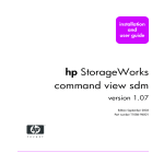
(1) Remote monitoring of PLC CPU via Internet
The Web server function allows users to monitor PLC CPUs at a remote location
using a commercially available Web browser on a personal computer connected
to the Internet/Intranet.
Internet
(General public line)
Internet service
provider (ISP)
Internet service
provider (ISP)
(2) Accesses from
personal computer
to Web server module.
Intranet
(Factory/Production site)
Web server module
Personal computer
Modem
Device
data
(1) Web server module
collects device data.
MELSECNET/H etc.
(3) Using Web browser,
controls and monitors
the PLC field devices.
1-1
1-1
1
1 OVERVIEW
MELSEC-Q
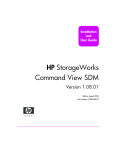
(2) Collection/Display of tag data (Tag function)
A set of individual PLC CPU's device data on a network is entered as a tag and
the Web server module collects those device data in tag unit.
The collected data can be displayed in a Web browser by specifying a tag name.
1
(2) Collects device data
in tag unit according
to the tag setting.
External device
(Client)
Web server module
(3) Specifies a tag
name to display
the tag data.
Tag data
CPU1:
Device
D100
D200
D300
D400
Value
100
20.3
9
70
(Component name)
Tag setting
Pressure
Temperature
Tag name :
01: Process A
Water level
Humidity
Component name
Value
1280
(Component name)
Tag name:
01: Process A
CPU name Device
Component name
Value
Pressure
CPU1
D100
Pressure
100
Temperature
CPU1
D200
Temperature
20.3
Water level
CPU1
D300
Water level
9
Humidity
CPU1
D400
Humidity
70
CPU2
D10
Quantity of production
1280
Quantity of production
CPU2:
Device
D10
Tag data monitor
(1) Sets a tag and its components
in Web browser.
Quantity of production
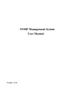
(3) Display of tag data logging/logging result (Logging function)
Tag data can be stored as a CSV file in time series at the user-specified
execution timing (by setting timing, start/stop condition).
The stored file can be displayed in a Web browser or downloaded by FTP
operation, etc.
Web server module
(2) According to the logging setting,
Web server module logs
tag data.
Tag data
External device
(Client)
(3) Specifies a logging
name to display the
logging data.
Logging data
Logging setting
Tag name:
Logging interval (seconds)
Process A
Interval specification (300 seconds)
Process B
Interval specification (60 seconds)
Process C Time specification (05:00:00)
(1) Makes logging setting in
Web browser.
Logging monitor
Logging name:
Process A
Date
Display form:
List (*)
Pressure Temperature Water level
02/07/01 09:00:00
90
20.3
9
02/07/01 09:05:00
97
20.5
7
02/07/01 09:10:00
101
20.4
8
02/07/01 09:15:00
100
20.4
10
02/07/01 09:20:00
103
20.2
13
Logging data can be viewed as a list or a graph.
1-2
1-2
1 OVERVIEW
MELSEC-Q
(4) Data write from Web browser to PLC CPU
Using the standard screen or user screen, device data or tag data can be written
from the Web browser to the PLC CPUs.
While data can be written in word unit, ON/OFF data can be used for ON/OFF
operation in bit unit.
Web server module
Requests for writing
in the device test or
user part.
External device
(Client)
MELSECNET/H, etc.
1-3
1-3
1 OVERVIEW
MELSEC-Q
(5) Event monitoring/History display (Event monitor function)
The Web server module can monitor the PLC CPU status (CPU monitor), tag
data (tag monitor) and time (time/interval monitor), and store the historical data of
occurred events into CSV files.
The stored files can be displayed in a Web browser or downloaded by FTP
operation.
The e-mail transmission at event occurrence is also available.
Web server module
(2) According to event setting,
Web server module performs
monitoring.
Tag monitor
External device
(Client)
(3) Displays event
histrical data on the
Event history monitor.
Time/
interval monitor
Tag data
CPU monitor
Event setting
Event history monitor
Tag Component
Trigger
Condition
name
name
value
Process A
Pressure
Process A Temperature
Process A Water level
120
30
200
(1) Makes event setting using Web
browser.
Event type:
Tag event
Date
Status
02/07/01 09:00:00 Occurrence
02/07/01 12:55:10 Occurrence
02/07/02 14:10:00 Occurrence
(4) Sending e-mail upon
event occurrence is
available.
Web server module
Tag
name
Component
Condition
name
Process A Water level
Process A
Pressure
Process A Temperature
External device
(Client)
E-mail
Event
occurred
Tag data
Logging data
1-4
1-4
1 OVERVIEW
MELSEC-Q
(6) Storage of logging data before and after event occurrence (Logging
function)
By setting the occurrence of an event as the start/stop condition of logging,
logging data before and after event occurrence can be stored.
This enables only necessary data to be stored without the logging data before
and after event occurrence being buried in the file.
Web server module
Event
occurrence
After event occurrence, logging
stops in specified time.
1-5
2003/11/01 13:54:00
2003/11/01 13:54:14
2003/11/01 13:54:24
2003/11/01 13:54:34
2003/11/01 13:54:44
2003/11/01 13:54:54
2003/11/01 13:55:04
2003/11/01 13:55:14
2003/11/01 13:55:24
2003/11/01 13:55:34
2003/11/01 13:55:44
2003/11/01 13:55:54
2003/11/01 13:56:04
2003/11/01 13:56:14
2003/11/01 13:56:24
2003/11/01 13:56:34
2003/11/01 13:56:44
2003/11/01 13:56:54
Data before and after
event occurrence are
always located in the
latest positions.
1-5
1 OVERVIEW
MELSEC-Q
(7) Data transmission/Alarm notification by e-mail (E-mail function)
(a) E-mail transmission by PLC CPU
With the dedicated instruction (WMSEND), a tag data/logging data/user
data file can be sent as an attached file of e-mail.
(1) Makes required setting for e-mail in
control data of dedicated instruction.
PLC CPU
[ZP.WMSEND]
Web server module
Subject
(ASCII data)
Subject
(ASCII data)
Main text
(ASCII data)
Main text
(ASCII data)
Tag/Logging No.
User data file name
Tag data
Logging data
User data file
Attached file
(Binary/CSV data)
Mail server
(2) Sends an e-mail by
dedicated instruction
(WMSEND).
(b) E-mail transmission by event monitor function
Event setting enables transmission of an event data, tag data or logging
data by e-mail when an event occurs.
PLC CPU
(1) Performs monitoring
according to event
setting.
Web server module
CPU monitor
Tag monitor
Time/
interval monitor
Event
conditions
satisfied
2002/07/01 09:00:00
Tag data
Logging data
(2) According to the tag
setting, collects device
data in tag unit.
1-6
Subject
(ASCII data)
Main text
(ASCII data)
Attached file
(CSV data)
Mail server
(3) When event conditions
are satisfied, an e-mail
will be sent.
1-6
1 OVERVIEW
MELSEC-Q
(8) Read/Write of file by FTP (FTP function)
(a) FTP client function
1) FTPPUT instruction
The tag data/logging data/user data file stored in the Web server
module can be written to an external device (FTP server).
PLC CPU
External device
(FTP server)
Web server module
(FTP client)
Write (Upload)
Program
Tag
Tag
[ZP.FTPPUT ]
Logging
User data
Logging
User data
2) FTPGET instruction
The user data file stored in the external device (FTP server) can be
read to the Web server module.
PLC CPU
External device
(FTP server)
Web server module
(FTP client)
Read (Download)
Program
[ZP.FTPGET ]
User data
User data
(b) FTP server function
The files stored in the Web server module can be read/written from the
external device (FTP server).
PLC CPU
Web server module
(FTP server)
External device
(FTP client)
Read (Download)
Logging
Logging
User HTML
User HTML
Write (Upload)
Event history
Event history
Setting data
User data
1-7
Setting data
User data
1-7
1 OVERVIEW
MELSEC-Q
(9) Read/write of user data file by PLC CPU (Dedicated instructions)
(a) WFREAD instruction
The user data file on the compact flash card mounted on the Web server
module can be read to the device data of the PLC CPU.
PLC CPU
Web server module
Program
[ZP.WFREAD ]
Device data
User data
(Example) User data file reading
Transfer the recipe data created with the personal computer to
the Web server module, and read the data from the Web server
module to the device data of the PLC CPU with the WFREAD
instruction. ( 1)
PLC CPU
2)
External device
(FTP client)
Web server module
(FTP server)
Program
CF file
read command
[ZP.WFREAD ]
3)
1)
Device data
Recipe data
Recipe data
1) Transfer the recipe data created with the personal computer to the Web server
module.
2) Give a file read command from the user screen.
3) Read the recipe data to the PLC CPU with the dedicated instruction (WFREAD).
1 File transfer to the Web server module can also be performed with the dedicated instruction (FTPGET).
(b) WFWRITE instruction
The device data of the PLC CPU can be written to the user data file of the
compact flash card mounted on the Web server module.
PLC CPU
Web server module
Program
[ZP.WFWRITE ]
Device data
1-8
User data
1-8
1 OVERVIEW
MELSEC-Q
(10) Easy Web server (Web server module) system configuration by
setting in Web browser
Setting in a Web browser allows easy Web server system configuration.
Once the Web server module is connected to the network, users can monitor
device data on the standard screen of the Web server module.
Web server module
Personal computer (Web browser)
[Various settings (Administrative menu)]
Standard screen HTML
Various settings
Administrative
menu
Monitor screen
[Monitor screen]
Monitor screen display
(11) Creation of user screens using parts supplied as standard
Creating HTML files using the standard-supplied user parts (applet, SSI, CGI
parts) allows the user to make original Web screens.
[Applet parts]
1-9
[SSI, CGI parts]
1-9
1 OVERVIEW
MELSEC-Q
(12) Compatibility with a variety of connection methods
(a)
A connection method that meets a user's network environment can be
selected.
Web server module
External device
(Client)
ADSL
Analog modem
LAN
For connection to the Internet, sign-up with the Internet service provider is required in advance.
(b)
The Web server module can be connected to an ADSL line via a UPnPcompatible broadband router.
1) By merely connecting the Web server module to an ADSL line, it can
be connected to the network without taking account of the NAT setting
of the router.
2) In the environment where a global IP address is dynamically assigned,
the Web server module can obtain the global IP address from the
router and notify the client of the address.
(Example) Using ADSL modem (router type, UPnP compatible)
Using the router type ADSL modem, a single ADSL line can be
shared with the personal computer, etc.
Using the security functions, e.g. firewall and VPN, of the router
prevents illegal entrance from external networks.
(Plant/Production field)
Personal computer,
etc.
Internet
Web server module
Client
ADSL
(Telephone line)
ADSL modem
(Router type, UPnP compatible)
Local IP address
Exchange station
ISP
Global IP address
UPnP communication
(global IP address
obtaining, NAT setting)
1 - 10
1 - 10
1 OVERVIEW
MELSEC-Q
(13) Seamless access beyond network hierarchies
Using the Web server module as a gateway, the statuses of the PLC CPUs
connected hierarchically with Ethernet, MELSECNET/H and/or CC-Link can be
monitored and those data can be collected.
(14) High capacity and backup memory
(a) Processing of large data volume
Large volume of data that is beyond capability of the PLC CPU can be
TM
processed using the standard ROM and Compact Flash card.
Saving device data in file format and accessing them from a remote
location is available using Web browser or FTP.
(b) Backup/Restoration of standard ROM data
The data (setting information, logging data, user HTML, etc.) of the
TM
standard ROM can be backed up on the Compact Flash card. It is also
TM
possible to restore the data of the Compact Flash card onto the standard
ROM.
(c) Power off without shut-down operation
The file protection battery allows power to be switched on/off any time
without troublesome shut-down operation. (When a battery is installed)
(15) Prevention of illegal access by user authentication and IP filter
functions
(a)
By basic authentication of the user name and password, the Web server
module can restrict access of users and setting operations.
(User authentication function)
(b)
The IP address of the access source can be identified to restrict access.
(IP filter function)
(Example) Using IP filter function
When access is made from an intra-company LAN (client 1), 2)),
registering the IP address of the proxy server to the IP filter
shuts off external access (client 3)), enabling access from only
the intra-company LAN.
(Plant/Production field)
Client 3)
Web server module
Client 2)
3)
2)
1)
Internet
Proxy server
Intra-company
LAN
Client 1)
1 - 11
1 - 11
2 SYSTEM CONFIGURATION
MELSEC-Q
2 SYSTEM CONFIGURATION
This chapter explains the system configuration of the Web server module.
2.1 Applicable Systems
2
This section explains the applicable systems.
(1) Applicable modules and number of mountable Web server modules
The following table shows the CPU module compatible with web server module
and the number of mountable web server modules.
Applicable module
CPU module
Number of mountable
web server modules
Q00JCPU
Maximum 8
Q00CPU
Q01CPU
Maximum 24
Q02CPU
Q02HCPU
Q06HCPU
Q12HCPU
Q25HCPU
Remarks
( 1)
Maximum 64
Q12PHCPU
Q25PHCPU
1 Refer to the User's Manual (Function Explanation/Programming Basic) of the CPU
module.
(2) Mountable position on base unit
The Web server module can be mounted on any I/O slot ( 2) of the base unit.
2 Limited to within the I/O point range of the CPU module.
(3) Application to multiple CPU system
The Web server module is compatible with a multiple CPU system.
When using the Web server module in a multiple CPU system, refer to the User's
Manual (Function Explanation/Programming Basic) of the CPU module used first.
(4) Compatible software package
The following table shows the systems where the Web server module will be
used and the corresponding software package.
It should be noted that GX Developer is not capable of accessing the PLC CPU
via the Web server module.
Software version
Q00J/Q00/Q01CPU
Q02/Q02H/Q06H/Q12H/
Q25HCPU
Q12PH/Q25PHCPU
2-1
Single CPU system
Multiple CPU system
Single CPU system
Multiple CPU system
Single CPU system
Multiple CPU system
GX Developer
Version 7 or later
Version 8 or later
Version 4 or later
Version 6 or later
Version 7.10L or later
2-1
2 SYSTEM CONFIGURATION
MELSEC-Q
2.2 Network Connections
This section explains the connection methods of the Web server module to the
network.
(1) LAN connection
2
The Web server module can be connected to a LAN using the 10BASET/100BASE-TX interface.
Web server module
Twisted pair cable
Ethernet
Intranet
External device
(2) Connection via ADSL modem
The Web server module can be connected to the Internet through ADSL modem
using 10BASE-T/100BASE-TX interface.
(a) When using bridge type ADSL modem
Web server module
Twisted pair cable
General
public line
Ethernet
PPPoE
ISP
Internet
ISP
ADSL modem
External device
(b) When using router type ADSL modem ( 1) ( 2)
Web server module
Twisted pair cable
General
public line
Ethernet
IP
ISP
Internet
ISP
ADSL modem
External device
(c) When using bridge type ADSL modem + broadband router
( 1) ( 2)
Web server module
Twisted pair cable
General
public line
Ethernet
IP
PPPoE
ISP
Internet
ISP
ADSL modem
Broadband router
2-2
External device
2-2
2 SYSTEM CONFIGURATION
MELSEC-Q
1 It is recommended to use a UPnP-compatible product.
When the product is incompatible with UPnP, contract on a static IP
address with an Internet service provider and the NAT setting on the
router are required.
2 Independently of whether the product is compatible or incompatible with
UPnP, the initial setting of the modem or router must be made before
start-up.
POINT
(1) Internet connection via ADSL modem is made in dial-up setting. (Refer to
Section 4.6.4.)
(2) A global IP address is assigned to the Web server module by the Internet
service provider.
With the address notification function, the external device can be informed of
the IP address that the Web server module has acquired. (Refer to Section
6.9.)
(3) Connection via analog modem
The Web server module can be connected to the Internet through analog modem
using the RS-232 interface.
Web server module
RS-232 cable
General public line
ISP
Internet
ISP
Modem
External device
POINT
(1) Internet connection via analog modem is made in dial-up setting. (Refer to
Section 4.6.4.)
(2) A global IP address is assigned to the Web server module by the Internet
service provider.
With the address notification function, the external device can be informed of
the IP address that the Web server module has acquired. (Refer to Section
6.9.)
2-3
2-3
2 SYSTEM CONFIGURATION
MELSEC-Q
2.3 System Configuration for Initial Setting, Maintenance and Inspection
This section shows a system configuration in the case of initial setting (system setting,
dial-up setting), maintenance and inspection of the Web server module.
(1) System configuration for initial setting, maintenance and inspection
by Web browser
Web server module
Twisted pair cable
(crossing cable)
Ethernet
External device
or
Web server module
Twisted pair cable
(straight cable)
Ethernet
Hub
External device
POINT
(1) Set the same network address to the Web server module and external device.
(2) When changing the Web server module's IP address after initial setting,
change the system setting to the default by the switch setting of GX Developer
and make initial setting again.
(Refer to Section 4.7 for the switch setting of GX Developer.)
(2) System configuration for switch setting, sequence program creation
and PLC diagnostics by GX Developer
Web server module
RS-232 cable
or
USB cable
External device
CPU module
2-4
2-4
2 SYSTEM CONFIGURATION
MELSEC-Q
2.4 Connection Device
This section explains the devices compatible with the Web server module.
(1) Compact FlashTM card
TM
The Compact Flash card applicable to the Web server module is a TYPE I
TM
storage card that meets the Compact Flash specifications.
TM
One Compact Flash card can be set to the Web server module.
POINT
TM
The Compact Flash card has its own lifetime (the limited number of writes).
For details, check the specifications of each product.
(2) Analog modem
The following table provides the specifications of the analog modem applicable to
the Web server module.
Item
Specifications
Operable with the interface specifications of the CH2 (RS-232) side on the
Web server module side interface
Web server module (refer to Section 3.1)
Data communication control command
Compatible with AT command of Hayes
DR Signal Control
Can turn on only the DR (DSR) signal independently
(3) ADSL modem
The following table provides the specifications of the ADSL modem applicable to
the Web server module.
Item
Web server module side interface
Specifications
Operable with the interface specifications of the CH1 (10BASET/100BASE-TX) side of the Web server module (refer to Section 3.1).
Protocol
PPPoE (PPP over Ethernet) or PPPoA (PPP over ATM)
Connection form
Bridge type or router type ( 1)
1 Use the router type ADSL modem that satisfies the following.
• The modem has the NAT (address conversion) function.
• The modem is compatible with Universal Plug and Play (UPnP).
• When the modem is incompatible with UPnP, it is necessary for the user to make a
contract on a static IP address with an Internet service provider and make the NAT
setting of the router.
2-5
2-5
2 SYSTEM CONFIGURATION
MELSEC-Q
(4) Broadband router
The following table provides the specifications of the broadband router applicable
to the Web server module.
Item
Specifications
Operable with the interface specifications of the CH1 (10BASE-
Web server module side interface
T/100BASE-TX) side of the Web server module (refer to Section 3.1).
NAT
Should have the NAT (address conversion) function.
UPnP
Should be compatible with Universal Plug and Play (UPnP). ( 2)
2 When the broadband router is incompatible with UPnP, it is necessary for the user to
make a contract on a static IP address with an Internet service provider and make the
NAT setting of the router.
(5) Twisted pair cable
Use the twisted pair cable that meets IEEE802.3 10BASE-T/100BASE-TX
standards.
(a) For 100Mbps
Use either of the following cables.
1) Unshielded twisted pair cable (UTP cable), Category 5
2) Shielded twisted pair cable (STP cable), Category 5
(b) For 10Mbps
Use either of the following cables.
1) Unshielded twisted pair cable (UTP cable), Category 3 (4, 5)
2) Shielded twisted pair cable (STP cable), Category 3 (4, 5)
POINT
During the high speed communication (100Mbps) via 100BASE-TX connection, a
communication error may occur due to the effect of high frequency noise generated
from the device other than PLC, depending on the installation environment.
Take the following countermeasures on the Web server module side to eliminate
the effect of high frequency noise.
(1) Wiring
• Do not bundle the twisted pair cables with the main circuit or power cables or
bring them close to each other.
• Make sure to place the twisted pair cable in a duct.
(2) Cable
• In the environment where the cable is susceptible to noise, use the shielded
twisted pair cable (STP cable).
(3) 10Mbps communication
• Connect the 10Mbps-compatible device with Web server module, and then
transmit the data to the device at transmission speed of 10Mbps.
2-6
2-6
2 SYSTEM CONFIGURATION
MELSEC-Q
(6) RS-232 cable
Use the RS-232-compliant cable of up to 15m.
[Recommended cable]
7/0. 127 P HRV-SV... Specify the number of pairs in
(for 13 pairs, specify 7/0. 127 13P HRV-SV.)
(Oki Electric Cable Company, Limited)
.
(7) Internet service provider
The following table provides the specifications of the Internet service provider to
be connected to the Web server module.
Item
Protocol
Authentic method
IP address
E-mail (When being set)
2-7
Specifications
PPP (Point to Point Protocol)
PAP or CHAP (Operable without authentication)
Global IP address must be assigned. ( 3)
SMTP server must be prepared.
3 When using a UPnP-incompatible router type ADSL modem or broadband router, it is
necessary for the user to make a contract on a static IP address with an Internet
service provider and make the NAT setting of the router.
2-7
2 SYSTEM CONFIGURATION
MELSEC-Q
2.5 Checking Function Version
This section explains how to check the function version of the Web server module.
(1) Checking at "SERIAL" section in the rating plate on the Web server
module
Serial No. (first 5 digits)
Function version
Compliant standard
(2) Checking with GX Developer
The function version of the Web server module is shown on the "Product
Information List" or "Module's Detailed Information" screen of GX Developer.
The following explains how to check the function version on the "Product
Information List" screen. (Refer to Section 9.2.2 for the "Module's Detailed
Information" screen.)
• The function version of the Web server module is displayed in the Ver.column.
[Startup procedure]
[Diagnostics] [System monitor]
2-8
"Product Inf. List"
2-8
3 SPECIFICATIONS
MELSEC-Q
3 SPECIFICATIONS
This chapter provides information on the performance specifications, transmission
specifications, etc. of the Web server module.
For the general specifications of the Web server module, refer to the user's manual of
the CPU module.
3.1 Performance Specifications
This section shows the performance specifications of the Web server module.
(1) Transmission and Interface specifications
3
Item
Specifications
10BASE-T/100BASE-TX
Interface ( 1)
Data transmission speed
10BASE-T
100BASE-TX
10Mbps
100Mbps
Transmission method
Base band
Number of cascaded stages
Cascade connection Maximum 4 stages
Maximum segment length ( 2)
Supported function
Cascade connection Maximum 2 stages
100m
Auto negotiation function (automatically recognizes 10BASE-T/10BASE-TX)
RS-232
Interface
Compliance with RS-232 (D-sub 9 pin)
Communication method
Full-duplex communication
Synchronization method
Start-stop synchronization method
Transmission speed
9600, 19200, 38400, 57600, 115200 bps
Transmission distance
Maximum 15m
Start bit
1
Data format Data bit
8
Stop bit
1
Parity check
None
Transmission control
Flow control (RS/CS control) is available
7/0. 127 P HRV-SV outside diameter: 8.5mm or longer
(Oki Electric Cable Company, Limited Specify the number of pairs in
Recommended cable
External wiring applicable connector
TM
Compact Flash
9 pin D-sub (Male) fixing type
card
Supply power voltage
3.3V 5%
Size
TYPE I card
Number of mountable cards
1
Number of occupied I/O points
32 points/1 slot (I/O assignment: intelligent 32 points)
Maximum number of writes for
Standard ROM (Flash ROM)
Maximum 100,000 times to one area (refer to Remarks (1))
Clock
Obtained from CPU No. 1 (every 60s) (Refer to Section 3.9)
5V DC internal current consumption
External dimensions
Weight
.)
0.65A
98 (3.86 in.) (H)
27.4 (1.08 in.) (W)
90 (3.54 in.) (D) [mm]
0.17kg (0.37Ib.)
1 Web server module recognizes 10BASE-T/10BASE-TX according to the external device.
For connection with the hub that does not have the auto negotiation function, set the hub
side to the half-duplex communication mode.
2 Distance between the hub and node.
3-1
3-1
3 SPECIFICATIONS
MELSEC-Q
(2) Software specifications
Item
Number of
simultaneously
connectable nodes
HTTP version
Specifications
5
1.0
Standard ROM: Maximum 5MB
TM
When Compact Flash card is used: Maximum 1GB
(Including the home page capacity and logging capacity)
Java applet: 15 types, SSI: 1 type, CGI: 3 types
(The file included as standard can be used (cannot be created by the user))
Web server
User area capacity
Parts for creating
user screen
Valid browser
Browser
E-mail
FTP server
FTP client
R
Internet Explorer 5.5/6.0 of Microsoft Corporation (Refer to (4) in Remarks)
R
Microsoft VM Build number: 3309 or later ( 1) (Refer to (2) in Remarks)
Sun Microsystems JRE (J2SE) v1.4.1_02 or later (Refer to (3) in Remarks)
Maximum 373 words
Maximum 960 words
Maximum 256k words (512k bytes)
MIME Format
1.0
CSV or binary format
Attached file cannot be divided
None
None
Java VM
Subject
Main text
Attached file
Attached file format
MIME version
Attached file Data
Division
Encryption
Compression
Communication with
mail server
Operation check
mailer
Others
Server function
Number of
simultaneously
connectable nodes
Client function
SMTP (send server) port number = 25
R
R
Internet Explorer 5.5/6.0 of Microsoft Corporation (Outlook Express 5.5/6.0)
POP before SMTP compatible
Provided
10
Provided (PUT, GET)
Account number: Maximum 16
User authentication
(User ID: 1 to 20 characters, password: 8 to 14 characters)
Security
Access log
Maximum 500
IP filter
Registration number: Maximum 32
No. of tags: Maximum 64, No. of components: Maximum 4096
Tag
(maximum 64 components for each tag)
Logging
No. of logging: Maximum 64, No. of lines (number of records): Maximum 10000 lines
Data collection
• When "Sampling: Execute at high speed" is selected in tag setting (control CPU only):
100 to 60000ms (total number of device points: Maximum 96)
Sampling interval
• When "Sampling: Execute" is selected in tag setting:
1 to 32767ms (number of components: Maximum 4096)
R
1 There are some restrictions on the use of audio parts in Microsoft VM. (Refer to Section
7.2.6 (4).)
Remarks
(1) Number of writes for Standard ROM (Flash ROM)
Data can be written to the same area of a standard ROM up to 100,000 times
and the life of a standard ROM drive is limited as shown below.
(a) Standard ROM drive life
Life of standard ROM drive (days) = 737000/write size per day (MB)
3-2
3-2
3
3 SPECIFICATIONS
MELSEC-Q
(Example) When executing 4 logging settings in which 64 "single word"-datatype components are to be collected at intervals of 10 seconds
LS=20+(18+1) 64+1=1237 bytes
Write size per day = 1237 (86400/10) 4 = 40.7MB
Life of standard ROM drive life = 737000/40.7MB = 18542 days =
50.8 years
LS: Write size to logging file at one time
For calculation of the size of the data written to the standard ROM drive
per day, refer to Appendix 7.1.
(b) Checking standard ROM drive usage
Used condition of a standard ROM drive can be checked by the number of
standard ROM erasure in the buffer memory area (buffer memory: 10 to
11).
When a standard ROM is erased frequently, take appropriate measures
such as stopping logging or changing the storage location of the logging file
TM
to Compact Flash card.
R
R
(2) Checking the Build number of Microsoft VM and downloading Microsoft VM
(a) Checking the Build number of Microsoft VM
By entering "jview" on the MS-DOS Prompt (command prompt) screen, the
Build number of Microsoft VM can be checked as shown below. ( )
R
R
R
When not displayed as below, Microsoft VM has not been installed and
must be installed. (Refer to (b).)
[Execution example]
The following is an example in which the above operation is executed on
the MS-DOS prompt of Microsoft Windows 98 operating system.
In this case, the Build number of Microsoft VM is "3802".
R
R
R
R
(b) Downloading Microsoft VM
When Microsoft VM has not been installed or the Build number of
Microsoft VM is earlier than "3309", download Microsoft VM of the latest
version (Windows Update, etc.) from the Microsoft Corporation Home
Page.
R
R
R
R
3-3
R
3-3
3 SPECIFICATIONS
MELSEC-Q
(3) Downloading Sun Microsystems Inc. Java VM and confirming its version
(a) Downloading Sun Microsystems Inc. Java VM
When using Sun Microsystems Inc. Java VM, download it from the Sun
Microsystems Inc. Home Page.
(b) Confirming version
The version can be confirmed by choosing the following.
[Control] "Java Plug-in" <<About>> tab "Java(TM) Plug-in Control
Panel" on Windows
R
(c) Precautions for use of Java VM of Sun Microsystems Inc.
1) Installation
When installing Java VM of Sun Microsystems Inc. into an English
operating system (OS), select Custom Setup and enable the "Support
for Additional Languages" setting.
(4) Combinations of Operating Systems (OS) and Web browsers
The following table shows the combinations of the Operating Systems (OS) and
Web browsers. The proper operation as a client computer has been
confirmed.( 1) ( 2)
Operating system (OS)
Web browser
R
R
Microsoft Internet Explorer 6.0
(English version)
R
R
Microsoft Internet Explorer 5.5/6.0
(English version)
Microsoft Windows XP Professional Operating System
(English version)
Microsoft Windows 2000 Professional Operating System
(English version)
R
R
Microsoft Windows NT Workstation Operating System Version 4.0
(English version)
R
R
R
Microsoft Internet Explorer 5.5/6.0
(English version)
R
R
Microsoft Internet Explorer 5.5/6.0
(English version)
R
R
Microsoft Internet Explorer 5.5/6.0
(English version)
R
R
Microsoft Internet Explorer 6.0
(Japanese version)
R
R
Microsoft Internet Explorer 5.5/6.0
(Japanese version)
Microsoft Windows Millennium Edition Operating System
(English version)
Microsoft Windows 98 Operating System
(English version)
Microsoft Windows XP Professional Operating System
(Japanese version)
Microsoft Windows 2000 Professional Operating System
(Japanese version)
R
R
Microsoft Windows NT Workstation Operating System Version 4.0
(Japanese version)
R
R
R
R
R
Microsoft Internet Explorer 5.5/6.0
(Japanese version)
R
R
Microsoft Internet Explorer 5.5/6.0
(Japanese version)
R
R
Microsoft Internet Explorer 5.5/6.0
(Japanese version)
Microsoft Windows Millennium Edition Operating System
(Japanese version)
Microsoft Windows 98 Operating System
(Japanese version)
R
R
1 When displaying the TOP page of the standard screen using an operating system
and a Web browser of English version, do not click on the "Japanese" button
provided for link to the Japanese version.
Doing so may display an incorrect screen.
2 When displaying the standard screen of English version using an operating system
and a Web browser of Japanese version, words and phrases used by the operating
system (e.g. the "Cancel" button to a confirmation message) are displayed in
Japanese.
3-4
3-4
3 SPECIFICATIONS
MELSEC-Q
(5) Relationship between scan time of PLC CPU and maximum delay time of highspeed sampling
DT = 2
ST + 5 (unit: ms)
DT: Maximum delay time of high-speed sampling (See below)
ST: Scan time of PLC CPU
0
100
Scheduled sampling time
(Preset sampling time)
200
DT
Time (ms)
DT
: Actual sampling time
3.2 RS-232 Connector Specifications
The RS-232 connector specifications are shown below.
(1) RS-232 connector specifications
1
6
2
7
Signal
abbreviation
1
CD(DCD)
Data Carrier Detect
2
RD(RXD)
Received Data
3
SD(TXD)
Transmitted Data
Signal name
4
ER(DTR)
Data Terminal Ready
8
5
SG(GND)
Signal Ground
9
6
DR(DSR)
Data Set Ready
7
RS(RTS)
Request To Send
8
CS(CTS)
Clear To Send
9
CI(RI)
Ring Indicator
3
4
5
Pin No.
Signal direction
Web server module
Modem
(2) RS-232 interface connector
The Web server module uses the following RS-232 interface connector.
9 pin D-sub (Female) fixing type
Use either of the following products as a connector shell for the connection cable
on the Web server module side.
3M
Plug type: 8209-6009
Shell type: 3702-2209 M2.6
Tyco Electronics AMP K.K.
Plug type: 747904-2
Shell type: 747515 or 174469-2
Connector fitting screw (M2.6)
3-5
3-5
3 SPECIFICATIONS
MELSEC-Q
3.3 Function List
The following is the function list of the Web server module.
Function
Monitor
Description
Device monitor
Monitors device values.
Tag data monitor
Monitors tag data.
Logging monitor
Monitors logging data.
Function Event history
monitor
PLC diagnostics
monitor
Self-diagnostics
monitor
Monitors event histories.
Monitors PLC CPU operation status.
Monitors Web server module operation status.
Reference
Section
Section
6.2.1
Section
6.2.2
Section
6.2.3
Section
6.2.4
Section
6.2.5
Section
6.2.6
Stores a set of device data of individual PLC CPUs on a network as a tag, and
Tag function
collects those device data in tag unit.
Section 6.3
Collected data can be displayed in the Web browser.
Stores tag data as a CSV file in time series at the user-specified execution
Logging function
timing (by setting timing, start/stop condition).
The stored file can be displayed in the Web browser or downloaded by FTP
Section 6.4
operation, etc.
Monitors the PLC CPU status (CPU monitor), tag data (tag monitor) and time
(time/interval monitor), and stores the historical data of occurred events into
Event monitor function
CSV files.
The stored files can be can be displayed in the Web browser or downloaded by
Section 6.5
FTP operation.
At event occurrence, e-mail can be sent as necessary.
Used to send e-mail.
E-mail function
E-mail transmission by PLC CPU
Section 6.6
E-mail transmission by event monitor function
Used to transfer a file between the Web server module and external device.
FTP function
FTP server function
Section 6.7
FTP client function
Access log function
Used to record access from the external device to the Web server module.
Address notification function Used to notify the external device of the Web server module address.
Data management function
Backs up/restores the standard ROM, formats the compact flash card, and
performs CSV export/import.
Diagnostic function
Used to perform self-diagnostics and connection test of the Web server module.
User screen creation
Creates user-original Web screens using the standard-supplied user parts
function
(applet, SSI, CGI).
3-6
Section 6.8
Section 6.9
Section
6.10
Section
6.11
Chapter 7
3-6
3 SPECIFICATIONS
MELSEC-Q
3.4 Dedicated Instruction List
The following is a list of the dedicated instructions available for the Web server module.
Application
Instruction
E-mail transmission WMSEND
FTPPUT
FTP
Tag
Logging
Reference
Section
Sends e-mail.
Section 8.2
Transfers (PUT) a file to the FTP server.
Section 8.3
FTPGET
Transfers (GET) a file from the FTP server.
Section 8.4
TAG
Issues a tag collection command. (Triggers a tag collection.)
Section 8.5
LOG
Issues a logging command. (Triggers a logging.)
Section 8.6
LOGDEL
Deletes the saved file of logging data.
Section 8.7
WFWRITE
WFREAD
WFDEL
3-7
Description
Writes the device data of the PLC CPU to the user data file on the
compact flash card.
Reads the user data file on the compact flash card to the device data of
the PLC CPU.
Deletes the user data file on the compact flash card.
Section 8.8
Section 8.9
Section 8.10
3-7
3 SPECIFICATIONS
MELSEC-Q
3.5 Web Browser Setting Item List
The following is a list of the parameter setting items to be set on a Web browser.
Item
Description
Top page
This screen is displayed first when the URL of the Web server module is
specified.
Monitor screen
Monitors device data, tag data, logging data, event historical data, PLC
diagnostics and self-diagnostics.
Device monitor
Monitors device values.
Tag data monitor
Monitors tag data.
Logging monitor
Monitors logging data.
Reference
Section
Section 6.2
Event history monitor Monitors event historical data.
PLC diagnostics
monitor
Self-diagnostics
monitor
Administrative menu
3-8
Monitors PLC CPU operation status.
Monitors Web server module operation status.
Allows initial setting, various function setting, setting test, etc. for use of
the Web server module.
Only the user with administrator authority can use this menu.
System setting
Makes the initial setting required for network connection.
Be sure to perform this setting to use the Web server module.
Section
4.6.3
Dial-up setting
Makes setting required for Internet connection.
Access target CPU
setting
Sets the connection path to the access target CPU.
Tag setting
Makes setting for tag data collection.
Section 6.3
Logging setting
Sets the logging intervals, file capacity, etc. of logging data.
Section 6.4
FTP setting
Makes the setting to log in to the FTP server.
Section 6.7
E-mail setting
Sets the send server, e-mail address, etc.
Section 6.6
Event setting
Sets the event monitor conditions.
Section 6.5
Address notification
setting
Makes the setting to notify the external device of the Web server module's
Section 6.9
URL.
Account setting
Sets the account for making access to the Web server module.
IP filter setting
Sets the IP address at which access to the Web server module is
enabled/disabled.
4.6.5
Section
4.6.6
Data management
Backs up, restores and formats the compact flash card, and performs
CSV export/import.
Section
6.10
Setting test
Conducts connection tests such as e-mail transmission, file transfer and
PING tests.
Section
6.11
Access log
Displays the access log to the Web server module.
Setting update
Updates the setting made in the Administrative menu on the Web server
module operation.
Section
4.6.4
Section
4.6.7
Section
Section 6.8
Section
4.6.2 (3)
3-8
3 SPECIFICATIONS
MELSEC-Q
3.6 I/O Signals for PLC CPU
3.6.1 I/O signals list
The following is the I/O signal list of the Web server module for the PLC CPU.
The assignment of the I/O signals is shown, assumed that the Web server module is
mounted on Slot 0 of the main base unit.
If mounted on other than Slot 0, use the device numbers corresponding to the slot.
Device X indicates an input signal from the Web server module to the PLC CPU, and
device Y indicates an output signal from the PLC CPU to the Web server module.
Signal Direction Web server module
Device
PLC CPU
Device
Signal name
No.
Signal Direction PLC CPU
Web server module
Signal name
No.
Module READY
X0
Y0
ON: Module prepared
Use prohibited
OFF: Watch dog timer error occurrence
TM
X1
X2
X3
X4
X5
X6
X7
X8
Compact Flash
card setting status
ON: Set
OFF: Not set
File access status
ON: Stopped
OFF: Operating
Use prohibited
OFF: Not connected
Network connection processing
ON: Processing
OFF:
Network connection completion
ON: Connection completed
OFF:
Network disconnection processing
ON: Processing
OFF:
Network disconnection completion
ON: Disconnection completed
OFF:
X9
XA
XD
XE
XF
3-9
Y4
Y5
Y6
Y7
Y8
File access stop request
ON: Stop requested
OFF:
File access stop cancel request
ON: Stop request cancelled
OFF:
Use prohibited
Network connection request
ON: Connection requested
OFF:
Use prohibited
Network disconnection request
ON: Disconnection requested
OFF:
Use prohibited
Y9
Use prohibited
YA
For system
YC
XB
XC
Y2
Y3
Network connection status
ON: Connected
Y1
Device write disable request
ON: Disable
OFF: Enable
YB
CPU event status
ON: Event occurrence
OFF: Not occurred
Tag event status
ON: Event occurrence
Use prohibited
OFF: Not occurred
YD
Use prohibited
YE
YF
3-9
3 SPECIFICATIONS
MELSEC-Q
Signal Direction Web server module
Device
Signal name
No.
X10
X11
X12
X13
X14
X15
X16
X17
X18
X19
X1A
X1B
X1C
X1D
X1E
X1F
PLC CPU
ERR. LED status
ON: On, Flicker
OFF: Off
Tag collection error
ON: Error occurrence
OFF: Normal
Logging error
ON: Error occurrence
OFF: Normal
CPU event monitor error
ON: Error occurrence
OFF: Normal
Tag event monitor error
ON: Error occurrence
OFF: Normal
Time event monitor error
ON: Error occurrence
OFF: Normal
Access target CPU error
ON: Error occurrence
OFF: Normal
E-mail transmission error
ON: Error occurrence
OFF: Normal
FTP transfer error
ON: Error occurrence
OFF: Normal
Connection error
ON: Error occurrence
OFF: Normal
Signal Direction PLC CPU
Device
Signal name
No.
Y10
Web server module
Error clear request
ON: Error clear requested OFF:
Y11
Y12
Y13
Y14
Y15
Y16
Y17
Use prohibited
Y18
Y19
Y1A
Use prohibited
Y1B
Other error
ON: Error occurrence
OFF: Normal
Y1C
Y1D
Use prohibited
Y1E
Watch dog timer error
ON: Error occurrence
OFF: Normal
Y1F
Important
Do not output (turn on) the signal marked "use prohibited" among the I/O signals for
the PLC CPU.
Doing so can cause malfunction of the PLC system.
3 - 10
3 - 10
3 SPECIFICATIONS
MELSEC-Q
3.6.2 I/O signals details
The following table shows the details of the I/O signals of the Web server module.
(1) Input signals
Device
No.
Signal Name
Description
(1) Turns on when the Web server module becomes ready after the PLC is powered off and
X0
Module READY
then on or the CPU module is reset.
(2) Turns off when a watch dog timer error occurs in the Web server module.
X1
Compact FlashTM (1) Turns on when the Compact FlashTM card is set and File access status (X2) is off.
TM
card setting status (2) Turns off when the Compact Flash
card is not set or File access status (X2) is on.
(1) Is on during file access stop. ( )
The following operations are available during file access stop.
(a) Removing and setting the Compact FlashTM card. (Refer to Section 4.9.)
(b) Powering off during operation without battery. (Refer to Section 4.11.)
During file access stop,
1) Write of file to standard ROM is disabled.
2) Read from or write to Compact FlashTM card is disabled.
3) Tag collection, logging and event monitor are stopped.
(2) Is off during file access operation.
X2
File access status
File access stop request (Y2)
File access stop cancel request (Y3)
(Operating)
(Stopped)
(Operating)
File access status (X2)
CompactFlashTM card setting status
(X1)
Compact FlashTM card replacement
PLC power-OFF
3 - 11
3 - 11
3 SPECIFICATIONS
Device
No.
MELSEC-Q
Signal Name
Description
(1) Turns on when the Web server module is connected to the network.
(2) The Web server module is connected to the network. (Connection trigger) when:
(a) The PLC is powered off and then on or the CPU module is reset when "Automatic
connection to network at start-up." is set in the System setting. (Refer to Section
4.6.3)
(b) Network connection request (Y5) is turned from OFF to ON.
(c) A telephone call is made to the Web server module side modem when the CALL
function is set. (Refer to Section 4.6.4)
X4
Network
connection status
(d) E-mail transmission/file transfer is performed.
(3) The Web server module is disconnected from the network (Disconnection trigger) when:
(a) Network disconnection request (Y7) is turned from OFF to ON.
(b) No access is made from the external device within the preset time when the
disconnection function is set. (Refer to Section 4.6.4)
(c) E-mail transmission/file transfer is completed (when connected for
transmission/transfer (above (2) (d))
(d) Line disconnection is requested from the user screen (disconnection by line
disconnection part)
(e) Disconnection is made by the Internet service provider.
(f) The modem is powered off or the cable is disconnected.
(1) Is on while the Web server module is processing for connection to the network (during
dialing or authentication).
Turns on in response to any of the connection triggers shown in (2) of X4.
(2) Upon completion of the network connection processing, Network connection status (X4)
or Connection error (X19) turns on.
(a) When the network connection is normally completed, Network connection status
(X4) turns on.
(b) When the network connection is failed, Connection error (X19) turns on and a
corresponding error code is stored into the connection error code area (buffer
Network
X5
connection
memory: 30).
Connection trigger occurred
processing
Network connection
processing
(X5)
Network connection
status
(X4)
Connection error (X19)
3 - 12
When normally completed
When failed
3 - 12
3 SPECIFICATIONS
Device
No.
MELSEC-Q
Signal Name
Description
(1) Turns on at completion of connection made by Network connection request (Y5).
Does not turn on by any connection trigger other than Network connection request (Y5)
indicated in (2) of X4.
(2) Turns off when Network connection request (Y5) turns off.
( 1)
Network connection request (Y5)
Network
X6
Network connection
processing
(X5)
connection
completion
Network connection
completion
(X6)
Network connection status (X4)
Connection error (X19)
When normally completed
When failed
1 When Network connection request (Y5) is turned on while Network connection
status (X4) is on, Network connection processing (X5) turns off, and Network
connection completion (X6) turns on immediately.
3 - 13
3 - 13
3 SPECIFICATIONS
Device
No.
MELSEC-Q
Signal Name
Description
(1) Is on while the Web server module is processing for disconnection from the network.
Turns on in response to any of the disconnection triggers shown in (3) of X4.
(2) Upon completion of the network disconnection processing, Network connection status
(X4) turns off.
Disconnection trigger occurred
Network
X7
disconnection
processing
Network disconnection
processing
(X7)
Network connection status (X4)
(1) Turns on at completion of disconnection made by Network disconnection request (Y7).
Does not turn on by any connection trigger other than Network disconnection request
(Y7) shown in (3) of X4.
(2) Turns off when Network disconnection request (Y7) turns off.
Network disconnection
request
(Y7)
Network
X8
( 1)
Network disconnection
processing
(X7)
disconnection
completion
Network disconnection
completion
(X8)
Network connection status (X4)
1 When Network disconnection request (Y7) is turned on while Network connection
status (X4) is off, Network disconnection processing (X7) turns off, and Network
disconnection completion (X8) turns on immediately.
XD
CPU event status
XE
Tag event status
(1) Turns on when a CPU event occurs.
(2) Turns off when a CPU event is restored.
(1) Turns on when a tag event occurs.
(2) Turns off when a tag event is restored.
(1) Is on while the ERR. LED is on (during module continue error occurrence) or flickering
(during module stop error occurrence).
X10
ERR. LED status
(2) Turns off when the ERR. LED turns off by turning on Error clear request (Y10) with the
ERR. LED on. (Not for the case of flickering ERR. LED)
(3) While the ERR. LED is on or flickering (when X10 is on), one (or more) of X11 to X19
and X1C turns on.
(1) Turns on when an error of the tag collection occurs.
X11
Tag collection
error
(2) When this turns on, an error code is stored into the tag status area (buffer memory: 1000
to 1075).
(3) Turns off when Error clear request (Y10) is turned on.
3 - 14
3 - 14
3 SPECIFICATIONS
Device
No.
Signal Name
MELSEC-Q
Description
(1) Turns on when a logging error occurs.
X12
Logging error
(2) When this turns on, an error code is stored into the logging status area (buffer memory:
2000 to 2267).
(3) Turns off when Error clear request (Y10) is turned on.
(1) Turns on when an error of CPU event monitor occurs.
(2) When this turns on, an error code is stored into the CPU event monitor status area 1
X13
CPU event
monitor error
(buffer memory: 3300 to 3375). ( )
The statuses of CPU monitor setting No. 1 to 16 are also stored into the CPU event
monitor status area 2 (buffer memory: 3000 to 3018).
(3) Turns off when Error clear request (Y10) is turned on.
(1) Turns on when an error of tag event monitor occurs.
X14
(2) When this turns on, an error code is stored into the tag event monitor status area 1
(buffer memory: 10000 to 10447). ( )
Tag event monitor
The statuses of tag monitor setting No. 1 to 16 are also stored into the tag event
error
monitor status area 2 (buffer memory: 3100 to 3118).
(3) Turns off when Error clear request (Y10) is turned on.
(1) Turns on when an error of time event monitor occurs.
X15
Time event
monitor error
(2) When this turns on, an error code is stored into the time/interval event monitor status
area (buffer memory: 3200 to 3217).
(3) Turns off when Error clear request (Y10) is turned on.
X16
X17
Access target
CPU error
E-mail
transmission error
(1) Turns on when a communication error of the access target CPU occurs.
(2) When this turns on, an error code is stored into the access target CPU setting status
area (buffer memory: 4000 to 4071).
(3) Turns off when Error clear request (Y10) is turned on.
(1) Turns on when an e-mail transmission error occurs.
(2) When this turns on, an error code is stored into the e-mail transmission status area
(buffer memory: 5000 to 5984).
(3) Turns off when Error clear request (Y10) is turned on.
(1) Turns on when an FTP transfer error occurs.
(2) When this turns on, an error code is stored into the following area of the buffer memory.
(a) Error related to FTP transfer (PUT): FTP client status (PUT) area (buffer memory:
X18
FTP transfer error
6002 to 6553)
(b) Error related to FTP transfer (GET): FTP client status (GET) area (buffer memory:
8002 to 8553)
(3) Turns off when Error clear request (Y10) is turned on.
X19
Connection error
(1) Turns on when network connection fails.
(2) When this turns on, an error code is stored into the connection error code area (buffer
memory: 30).
(3) Turns off when Error clear request (Y10) is turned on.
(1) Turns on when an error not corresponding to X11 to X19 occurs.
X1C
Other error
(2) When this turns on, the error code is stored into the error log area (buffer memory: 150
to 247).
(3) Turns off when Error clear request (Y10) is turned on. (Only when the module continue
error occurs)
X1F
3 - 15
Watch dog timer
error
Turns on when a watch dog timer error occurs.
3 - 15
3 SPECIFICATIONS
MELSEC-Q
(2) Output signal details
Device
No.
Y2
Y3
Signal Name
File access stop
(1) Turns on when file access is stopped.
request
(2) Refer to X2 for ON/OFF timing.
File access stop
(1) Turns on when a file access stop is canceled.
cancel request
(2) Refer to X2 for ON/OFF timing.
Network
Y5
connection
request
Network
Y7
Description
disconnection
request
(1) Turns on when the Web server module is connected to the network.
(2) Refer to X6 for ON/OFF timing.
(1) Turns on when the Web server module is disconnected from the network.
(2) Refer to X8 for ON/OFF timing.
(1) When this turns on, writing from the device test/tag component test by a write-authorized
YA
Device write
disable request
user is disabled.
(2) When this turns off, writing from the device test/tag component test by a write-authorized
user is enabled.
(1) Turning this on during module continue error occurrence (ERR. LED on) turns off the
ERR. LED and X10 to X19 and X1C. ( )
The ERR. LED does not turn off if Y10 is turned on during module stop error
Y10
Error clear request
occurrence (ERR. LED flicker).
(2) Clears the current error area (address: 140 to 145) of the buffer memory.
Clears the latest error code displayed in the system monitor of GX Developer. (Refer to
Section 9.2.2)
3 - 16
3 - 16
3 SPECIFICATIONS
MELSEC-Q
3.7 Buffer memory list
The buffer memory addresses are listed below.
Address
(Decimal)
Application
0
1
2
Module status
area
3
4
5 to 6
Name
RUN LED status
0: Off
1: On
ERR. LED status
0: Off
1: On
2: Flicker
Switch 1 status (Mode setting)
: Online
0000H
0001H
: Hardware test
0002H
: CH1 self-loopback test
0003H
: CH2 self-loopback test
270FH (9999)
: Module initialization mode
Switch 2 status (Default operation setting/battery error detection setting/logging
monitor setting)
1) Default operation setting (Account setting) (b0)
0: Operates according to the account setting.
1: Operates according to the default account setting.
2) Default operation setting (System setting/IP filter setting) (b1)
0: Operates according to the system setting/IP filter setting.
1: Operates according to the default system setting/IP filter setting.
3) Battery error detection setting (b2)
0: Detects battery error.
1: Not detect battery error.
4) Logging monitor setting (b4)
0: Displays the last update time of the file.
0: Not display the last update time of the file.
Switch 3 status (Response monitoring time setting)
15 to 255 (second): Response monitoring time ( )
When switch setting 3 is not set or any of 0 to 14 has been set, the
response monitoring time is 15 seconds.
7
Use prohibited
Module status
area
System area
Battery status
0: Normal
8 to 9
Use prohibited
System area
10 to 11
Module status
area
Number of standard ROM erasure
12 to 27
1: Battery error occurrence
31
32
33
34
35
36
37
38
39
40
41 to 42
43 to 44
45 to 46
Use prohibited
System area
Network
connection status Router external IP address
area ( 1)
Connection error code
0: Normal
Other than 0: Error code
Number of successful connection
Number of failed connection
Number of connection tries by request signal (Y5)
Number of connection tries by automatic connection
Number of reconnection tries
Network
Number
of times of connection retry occurrence
connection status
Number
of disconnection
area
Number of disconnection by request signal (Y7)
Number of automatic disconnection
Number of line lost times
Total connection time (Unit: Minute)
LAN connection time (Unit: Minute)
Modem connection time (Unit: Minute)
47 to 48
Use prohibited
28 to 29
30
Initial value
0
0
Reference
section
Section
4.3 (1)
0
Section 4.7
0
0
0
Section
4.10.3
Section 3.1
0 Remarks
0
Section
3.8.2
0
0
0
0
0
0
0
0
0
0
0
0
0
0
Section
3.8.2
System area
(Continued on the next page)
3 - 17
3 - 17
3 SPECIFICATIONS
MELSEC-Q
(From the preceding page)
Address
(Decimal)
Application
Name
49 to 50
Network
connection status ADSL connection time (Unit: Minute)
area
51 to 52
Use prohibited
Initial value
0
Current connection time (Unit: Minute)
0
55 to 56
IP address
0
57 to 58
Subnet mask
0
59 to 60
Default gateway
0
63 to 64
65
Network
DNS server address 1
connection status DNS server address 2
area
HTTP port number
0
0
66
67
Access point
1 to 3: Access point number being used
69
0
3: ADSL
0
Network
FTP port number
connection status Number of disconnections from user screen (number of disconnections using
area (*1)
line disconnection part)
IP address setting
0: "Obtain an IP address automatically."
1: "Use the following IP address."
70
0
0
IP address setting: IP address
C0A80303H
73 to 74
IP address setting: Subnet mask
FFFFFF00H
IP address setting: Default gateway
0
DNS server setting: DNS server address 1
0
DNS server setting: DNS server address 2
0
81
Web server setting
0 to 1023
: "Use the default HTTP port number (80)."
1024 to 65535
: "Use the following HTTP port number."
0
82
Network type setting
0: "Connecting through LAN or the router."
1: "Dial-up to the network (modem, ADSL)."
0
83
Automatic network connection setting at start-up
0: "No connection to network at start-up."
1: "Automatic connection to network at start-up."
0
FTP server setting
0 to 1023
: "Use the default FTP port number (21)."
1024 to 65535 : "Use the following FTP port number."
0
85
Web server setting Register the HTTP port number to NAT of the router.
0: Not register
1: Register
0
86
FTP server setting Register the FTP port number to NAT of the router.
0: Not register
1: Register
0
77 to 78
79 to 80
84
87 to 89
System setting
status area
System setting
status area (*1)
Use prohibited
91
92
93
Dial-up setting
status area
Section
4.6.3
Section
4.6.3
System area
Dial method
0: Tone
90
Section
3.8.2
0
71 to 72
75 to 76
Section
3.8.2
0
Connection method
0: LAN
1: Modem
68
Section
3.8.2
System area
53 to 54
61 to 62
Reference
section
1: Pulse
0
Retry: Number of retries.
0
Retry: Change access point automatically.
0: None
1: Provided
0
Modem attribute: Communication speed (Unit: bps)
0
Section
4.6.4
(Continued on the next page)
3 - 18
3 - 18
3 SPECIFICATIONS
MELSEC-Q
(From the preceding page)
Address
(Decimal)
94 to 97
Application
Name
Initial value
Use prohibited System area
98
Modem attribute: Call timeout (Unit: Second)
0
99
Modem attribute: Dial pause time (Unit: Second)
0
Modem attribute: Addition set
Addition AT command string
0
Modem attribute: CALL function
0: None
1: Provided
0
Modem attribute: Disconnect function, Disconnect time (Unit: Minute)
0
100 to 132
Dial-up setting
status area
133
134
135 to 139
Current error
(*1)
142 to 145
146 to 149
Error code
0: Normal
Other than 0: Error code
0
Section
3.8.5
0
Section
3.8.5
System area (Use prohibited)
Time
Use prohibited System area
150
Number of times of error occurrence
0
151
Error log write pointer
0
152
Error log 1
153
154 to 157
Error code
0: Normal
Other than 0: Error code
Date and time
0
Error log 2
(Same as Error log 1)
164 to 169
Error log 3
(Same as Error log 1)
170 to 175
Error log 4
(Same as Error log 1)
176 to 181
Error log 5
(Same as Error log 1)
Error log
Error log 6
(Same as Error log 1)
188 to 193
Error log 7
(Same as Error log 1)
194 to 199
Error log 8
(Same as Error log 1)
200 to 205
Error log 9
(Same as Error log 1)
206 to 211
Error log 10
(Same as Error log 1)
212 to 217
Error log 11
(Same as Error log 1)
218 to 223
Error log 12
(Same as Error log 1)
224 to 229
Error log 13
(Same as Error log 1)
230 to 235
Error log 14
(Same as Error log 1)
236 to 241
Error log 15
(Same as Error log 1)
Error log 16
(Same as Error log 1)
242 to 247
248 to 249
0
Section
3.8.6
System area (Use prohibited)
158 to 163
182 to 187
Section
4.6.4
Use prohibited System area
140
141
Reference
section
Section
3.8.6
Use prohibited System area
(Continued on the next page)
3 - 19
3 - 19
3 SPECIFICATIONS
MELSEC-Q
(From the preceding page)
Address
(Decimal)
Application
250 to 251
252
Name
Number of login times
0
Login history write pointer
0
253
254 to 255
Login history 1
256
Initial value
257 to 260
User number
0
Source IP address
0
Login type
1: Web login
0
2: FTP login
Date and Time
0
261 to 268
Login history 2
(Same as Login history 1)
269 to 276
Login history 3
(Same as Login history 1)
277 to 284
Login history 4
(Same as Login history 1)
Login history 5
(Same as Login history 1)
Login history 6
(Same as Login history 1)
301 to 308
Login history 7
(Same as Login history 1)
309 to 316
Login history 8
(Same as Login history 1)
317 to 324
Login history 9
(Same as Login history 1)
325 to 332
Login history 10
(Same as Login history 1)
333 to 340
Login history 11
(Same as Login history 1)
341 to 348
Login history 12
(Same as Login history 1)
349 to 356
Login history 13
(Same as Login history 1)
357 to 364
Login history 14
(Same as Login history 1)
365 to 372
Login history 15
(Same as Login history 1)
Login history 16
(Same as Login history 1)
285 to 292
293 to 300
Login history
373 to 380
381
Section
3.8.7
Use prohibited System area
382 to 383
IP filter ( 1)
384 to 799
Use prohibited System area
800 to 801
802 to 803
Collection
monitor cycle
804 to 999
Use prohibited System area
Number of times when IP packet is blocked
0
Current cycle (Unit: Second)
0
Maximum cycle (Unit: Second)
0
1000 to 1003
Tag setting data
0
1004 to 1007
Tag collection data
0
Tag collection error data
0
Tag collection 1 error code
0
1008 to 1011
1012
Tag status
Logging setting data
0
2004 to 2007
Logging execute data
0
2008 to 2011
Logging error data
0
2013
Logging status
Logging 1 data
2014 to 2015
2016 to 2267
2268 to 2999
Section
3.8.9
Section
3.8.10
Use prohibited System area
2000 to 2003
2012
Section
3.8.8
The composition of each area is the same as that of the tag collection 1
Tag collection 2 to
error code.
64 error codes
Refer to 2 for assignment of each area.
1013 to 1075
1076 to 1999
Reference
section
Logging 2 to 64
data
Error code
0: Normal
Other than 0: Error code
0
Number of saved files
0
Number of the latest saved file
0
Section
3.8.11
The composition of each area is the same as that of the logging 1 data.
Refer to 3 for assignment of each area.
Use prohibited System area
(Continued on the next page)
3 - 20
3 - 20
3 SPECIFICATIONS
MELSEC-Q
(From the preceding page)
Address
(Decimal)
Application
Name
Initial value
3000
CPU event setting data
0
3001
CPU event occurrence data
0
3002
CPU event monitor error data
0
3003
CPU event monitor 1 error code
0
3004
CPU event monitor 2 error code
0
3005
CPU event monitor 3 error code
0
3006
CPU event monitor 4 error code
0
3007
CPU event monitor 5 error code
0
3008
CPU event monitor 6 error code
0
3010
CPU event
CPU event monitor 7 error code
monitor status 2
CPU event monitor 8 error code
3011
CPU event monitor 9 error code
0
3012
CPU event monitor 10 error code
0
3013
CPU event monitor 11 error code
0
3014
CPU event monitor 12 error code
0
3015
CPU event monitor 13 error code
0
3016
CPU event monitor 14 error code
0
3017
CPU event monitor 15 error code
0
3018
CPU event monitor 16 error code
0
3009
3019 to 3099
Use prohibited
0
System area
Tag event setting data
3101
Tag event occurrence data
0
3102
Tag event monitor error data
0
3103
Tag event monitor 1 error code
0
3104
Tag event monitor 2 error code
0
3105
Tag event monitor 3 error code
0
3106
Tag event monitor 4 error code
0
3107
Tag event monitor 5 error code
0
3108
Tag event monitor 6 error code
0
0
3110
Tag event
Tag event monitor 7 error code
monitor status 2
Tag event monitor 8 error code
3111
Tag event monitor 9 error code
0
3112
Tag event monitor 10 error code
0
3113
Tag event monitor 11 error code
0
3114
Tag event monitor 12 error code
0
3115
Tag event monitor 13 error code
0
3116
Tag event monitor 14 error code
0
3117
Tag event monitor 15 error code
0
3118
Tag event monitor 16 error code
0
3119
Use prohibited
Section
3.8.13
0
3100
3109
Reference
section
0
0
Section
3.8.15
System area
(Continued on the next page)
3 - 21
3 - 21
3 SPECIFICATIONS
MELSEC-Q
(From the preceding page)
Address
(Decimal)
Application
Name
Initial value
3200
Time event setting data
3201
Time event monitor error data
0
3202
Time event monitor 1 error code
0
3203
Time event monitor 2 error code
0
3204
Time event monitor 3 error code
0
3205
Time event monitor 4 error code
0
3206
Time event monitor 5 error code
0
3207
Time event monitor 6 error code
0
Time event monitor 7 error code
0
3208
3209
Time/Interval
event monitor
status
0
Time event monitor 8 error code
0
3210
Time event monitor 9 error code
0
3211
Time event monitor 10 error code
0
3212
Time event monitor 11 error code
0
3213
Time event monitor 12 error code
0
3214
Time event monitor 13 error code
0
3215
Time event monitor 14 error code
0
3216
Time event monitor 15 error code
0
3217
Time event monitor 16 error code
0
3218 to 3299
Use prohibited
3300 to 3303
3304 to 3307
3308 to 3311
3312
3313 to 3375
3376 to 3999
0
CPU event occurrence data
0
Access target CPU setting data
0
4004 to 4007
Access target CPU error data
0
Access target CPU 1 error code
0
Access target
CPU setting
status
4009 to 4071
4072 to 4999
Use prohibited
Section
3.8.12
System area
4000 to 4003
4008
Section
3.8.16
System area
CPU event monitor setting data
CPU event
CPU event monitor error data
0
monitor status 1 CPU event monitor 1 error code
0
( 1)
The composition of each area is the same as that of the
CPU event monitor 2 to 64
CPU event monitor 1 error code.
error code
Refer to 4 for assignment of each area.
Use prohibited
Reference
section
The composition of each area is the same as that of the
Access target CPU 2 to 64
access target CPU 1 error code.
error code
Refer to 5 for assignment of each area.
Section
3.8.17
System area
(Continued on the next page)
3 - 22
3 - 22
3 SPECIFICATIONS
MELSEC-Q
(From the preceding page)
Address
(Decimal)
Application
Name
Initial value
5000
Number of times when WMSEND instruction was normally completed
5001
Number of times when WMSEND instruction failed
0
5002
Number of normally completed e-mail transmission
0
5003
Number of sent attached files
0
0
5004
Number of undelivered e-mails
0
5005
Number of writes for error log
0
5006
Error log write pointer
0
5007
Error code
0
5008
To
0
Subject
0
Error log 1
5009 to 5023
5024 to 5027
5028 to 5048
Date
0
Error log 2
(Same as Error log 1)
Error log 3
(Same as Error log 1)
Error log 4
(Same as Error log 1)
5091 to 5111
Error log 5
(Same as Error log 1)
5112 to 5132
Error log 6
(Same as Error log 1)
5133 to 5153
Error log 7
(Same as Error log 1)
5154 to 5174
Error log 8
(Same as Error log 1)
5175 to 5195
Error log 9
(Same as Error log 1)
5196 to 5216
Error log 10
(Same as Error log 1)
5217 to 5237
Error log 11
(Same as Error log 1)
5238 to 5258
Error log 12
(Same as Error log 1)
5259 to 5279
Error log 13
(Same as Error log 1)
5280 to 5300
Error log 14
(Same as Error log 1)
5301 to 5321
Error log 15
(Same as Error log 1)
5322 to 5342
Error log 16
(Same as Error log 1)
5049 to 5069
5070 to 5090
E-mail
transmission
status
5343
Transmission log write count
5344
Transmission log write pointer
5345
5346 to 5360
5361 to 5364
5365 to 5984
5985 to 5999
E-mail
transmission
status ( 1)
Section
3.8.18
0
0
To
0
Transmission log 1 Subject
0
Date
Transmission log
2 to 32
Reference
section
0
Section
3.8.18
The composition of each area is the same as that of the
transmission log 1.
Refer to 6 for assignment of each area.
Use prohibited System area
(Continued on the next page)
3 - 23
3 - 23
3 SPECIFICATIONS
MELSEC-Q
(From the preceding page)
Address
(Decimal)
6000
Application
FTP server
status
Name
Initial value
Number of successful logins
0
Number of failed logins
0
6002
Number of times when the FTPPUT instruction was normally completed
0
6003
Number of times when the FTPPUT instruction was abnormally completed
0
6004
Number of normally completed FTP transfers (PUT)
0
6005
Number of abnormally completed FTP transfers (PUT)
0
6006
Number of writes for error log
0
6007
Error log write pointer
0
6001
6008
6009
Error log 1
6010 to 6015
6016 to 6019
Error code
0
Transfer destination
0
Transferred file name
0
Date
Error log 2
(Same as Error log 1)
6032 to 6043
Error log 3
(Same as Error log 1)
Error log 4
(Same as Error log 1)
Error log 5
(Same as Error log 1)
6068 to 6079
Error log 6
(Same as Error log 1)
6080 to 6091
Error log 7
(Same as Error log 1)
6092 to 6103
Error log 8
(Same as Error log 1)
6104 to 6115
Error log 9
(Same as Error log 1)
6116 to 6127
Error log 10
(Same as Error log 1)
6128 to 6139
Error log 11
(Same as Error log 1)
6140 to 6151
Error log 12
(Same as Error log 1)
6152 to 6163
Error log 13
(Same as Error log 1)
6164 to 6175
Error log 14
(Same as Error log 1)
6176 to 6187
Error log 15
(Same as Error log 1)
6188 to 6199
Error log 16
(Same as Error log 1)
6200
Transfer log write count
6201
Transfer log write pointer
6202
6203 to 6208
FTP client status
Transfer log 1
(PUT) ( 1)
6209 to 6212
Section
3.8.19
0
6020 to 6031
FTP client
6044 to 6055
Status (PUT)
6056 to 6067
Reference
section
Section
3.8.20
0
0
Transfer destination
0
Transferred file name
0
Data
0
6213 to 6553
Transfer log 2 to The composition of each area is the same as that of the transfer log 1.
32
Refer to 7 for assignment of each area.
6554 to 8001 Use prohibited
System area
Section
3.8.20
(Continued on the next page)
3 - 24
3 - 24
3 SPECIFICATIONS
MELSEC-Q
(From the preceding page)
Address
Application
(Decimal)
8002
8003
8004
8005
8006
8007
8008
8009
8010 to 8015
8016 to 8019
8020 to 8031
8032 to 8043
8044 to 8055
8056 to 8067
8068 to 8079
8080 to 8091 FTP client status
8092 to 8103 (GET) ( 1)
8104 to 8115
8116 to 8127
8128 to 8139
8140 to 8151
8152 to 8163
8164 to 8175
8176 to 8187
8188 to 8199
8200
8201
8202
8203 to 8208
8209 to 8212
8213 to 8553
8554 to 9998 Use prohibited
9999
Module
initialization
request
Name
Number of times when the FTPGET instruction was normally completed
Number of times when the FTPGET instruction was abnormally completed
Number of normally completed FTP transfers (GET)
Number of abnormally completed FTP transfers (GET)
Number of writes for error log
Error log write pointer
Error code
Transfer source
Error log 1
Transferred file name
Data
Error log 2
(Same as Error log 1)
Error log 3
(Same as Error log 1)
Error log 4
(Same as Error log 1)
Error log 5
(Same as Error log 1)
Error log 6
(Same as Error log 1)
Error log 7
(Same as Error log 1)
Error log 8
(Same as Error log 1)
Error log 9
(Same as Error log 1)
Error log 10
(Same as Error log 1)
Error log 11
(Same as Error log 1)
Error log 12
(Same as Error log 1)
Error log 13
(Same as Error log 1)
Error log 14
(Same as Error log 1)
Error log 15
(Same as Error log 1)
Error log 16
(Same as Error log 1)
Transfer log write count
Transfer log write pointer
Transfer source
Transfer log 1
Transferred file name
Data
Transfer log 2 to The composition of each area is the same as that of the transfer log 1.
32
Refer to 8 for assignment of each area.
System area
Module initialization request
0: No request
1: During module initialization mode
(The system is set up when the CPU module is reset)
2: Module initialization request
3: Completed (The system is set up.)
Other than 3: Failed (The system is set up.)
10000 to
10015
Tag event
monitor status 1 Tag event monitor setting data
( 1)
10016 to
10063
Use prohibited
10064 to
10079
Tag event
monitor status 1 Tag event occurrence data
( 1)
10080 to
10127
Use prohibited
10128 to
10143
Tag event
monitor status 1 Tag event monitor error data
( 1)
10144 to
10191
10192
10193 to
10447
3 - 25
Use prohibited
Initial value
Reference
section
0
0
0
0
0
0
0
0
0
0
Section
3.8.21
0
0
0
0
0
0
Section
4.13
0
Section
3.8.14
0
Section
3.8.14
0
Section
3.8.14
0
The composition of each area is the same as that of
the tag event monitor 1 error code 1.
Refer to 9 for assignment of each area.
Section
3.8.14
System area
System area
System area
Tag event monitor 1 error code
Tag event
monitor status 1
Tag event monitor 2 to 256 error code
( 1)
3 - 25
3 SPECIFICATIONS
MELSEC-Q
1 Can be used in the product whose first 5 digits of serial No. are 05112 or later.
(Assigned as system area for the product earlier than that)
2 The following shows the assignment of error code area for the tag collection 1 to 64
(address: 1012 to 1075).
Name
Tag Collection 1 to 64 Error Code Area
1
2
3
4
5
6
7
8
9
10
1012
1013
1014
1015
1016
1017
1018
1019
1020
1021
11
12
13
14
15
16
17
18
19
20
Error code
1022
1023
1024
1025
1026
1027
1028
1029
1030
1031
21
22
23
24
25
26
27
28
29
30
Error code
1032
1033
1034
1035
1036
1037
1038
1039
1040
1041
31
32
33
34
35
36
37
38
39
40
Error code
1042
1043
1044
1045
1046
1047
1048
1049
1050
1051
41
42
43
44
45
46
47
48
49
50
1052
1053
1054
1055
1056
1057
1058
1059
1060
1061
51
52
53
54
55
56
57
58
59
60
Error code
1062
1063
1064
1065
1066
1067
1068
1069
1070
1071
61
62
63
64
Error code
1072
1073
1074
1075
Error code
Error code
3 The following shows the assignment of the logging 1 to 64 data area (address:
2012 to 2267).
Name
Error code
Number of
saved files
Number of the
latest saved
file
Error code
Number of
saved files
Number of the
latest saved
file
Error code
Number of
saved files
Number of the
latest saved
file
Error code
Number of
saved files
Number of the
latest saved
file
3 - 26
Logging 1 to 64 Data Area
1
2
3
4
5
6
7
8
9
10
2012
2016
2020
2024
2028
2032
2036
2040
2044
2048
2013
2017
2021
2025
2029
2033
2037
2041
2045
2049
2014,
2015
2018,
2019
2022,
2023
2026,
2027
2030,
2031
2034,
2035
2038,
2039
2042,
2043
2046,
2047
2050,
2051
11
12
13
14
15
16
17
18
19
20
2052
2056
2060
2064
2068
2072
2076
2080
2084
2088
2053
2057
2061
2065
2069
2073
2077
2081
2085
2089
2054,
2055
2058,
2059
2062,
2063
2066,
2067
2070,
2071
2074,
2075
2078,
2079
2082,
2083
2086,
2087
2090,
2091
21
22
23
24
25
26
27
28
29
30
2092
2096
2100
2104
2108
2112
2116
2120
2124
2128
2093
2097
2101
2105
2109
2113
2117
2121
2125
2129
2094,
2095
2098,
2099
2102,
2103
2106,
2107
2110,
2111
2114,
2115
2118,
2119
2122,
2123
2126,
2127
2130,
2131
31
32
33
34
35
36
37
38
39
40
2132
2136
2140
2144
2148
2152
2156
2160
2164
2168
2133
2137
2141
2145
2149
2153
2157
2161
2165
2169
2134,
2135
2138,
2139
2142,
2143
2146,
2147
2150,
2151
2154,
2155
2158,
2159
2162,
2163
2166,
2167
2170,
2171
3 - 26
3 SPECIFICATIONS
MELSEC-Q
Logging 1 to 64 Data Area
Name
41
42
43
44
45
46
47
48
49
50
Error code
2172
2176
2180
2184
2188
2192
2196
2200
2204
2208
Number of
saved files
2173
2177
2181
2185
2189
2193
2197
2201
2205
2209
Number of the
latest saved
file
2174,
2175
2178,
2179
2182,
2183
2186,
2187
2190,
2191
2194,
2195
2198,
2199
2202,
2203
2206,
2207
2210,
2211
51
52
53
54
55
56
57
58
59
60
Error code
2212
2216
2220
2224
2228
2232
2236
2240
2244
2248
Number of
saved files
2213
2217
2221
2225
2229
2233
2237
2241
2245
2249
Number of the
latest saved
file
2214,
2215
2218,
2219
2222,
2223
2226,
2227
2230,
2231
2234,
2235
2238,
2239
2242,
2243
2246,
2247
2250,
2251
61
62
63
64
Error code
2252
2256
2260
2264
Number of
saved files
2253
2257
2261
2265
Number of the
latest saved
file
2254,
2255
2258,
2259
2262,
2263
2266,
2267
4 The following shows the assignment of the CPU event monitor 1 to 64 error code
area (address: 3312 to 3375).
Name
CPU Event Monitor 1 to 64 Error Code Area
1
2
3
4
5
6
7
8
9
10
3312
3313
3314
3315
3316
3317
3318
3319
3320
3321
11
12
13
14
15
16
17
18
19
20
3322
3323
3324
3325
3326
3327
3328
3329
3330
3331
21
22
23
24
25
26
27
28
29
30
Error code
3332
3333
3334
3335
3336
3337
3338
3339
3340
3341
31
32
33
34
35
36
37
38
39
40
Error code
3342
3343
3344
3345
3346
3347
3348
3349
3350
3351
41
42
43
44
45
46
47
48
49
50
3352
3353
3354
3355
3356
3357
3358
3359
3360
3361
51
52
53
54
55
56
57
58
59
60
3362
3363
3364
3365
3366
3367
3368
3369
3370
3371
61
62
63
64
3372
3373
3374
3375
Error code
Error code
Error code
Error code
Error code
3 - 27
3 - 27
3 SPECIFICATIONS
MELSEC-Q
5 The following shows the assignment of error code area for the access target CPU
1 to 64 (address: 4008 to 4071).
Name
Access Target CPU 1 to 64 Error Code Area
1
2
3
4
5
6
7
8
9
10
4008
4009
4010
4011
4012
4013
4014
4015
4016
4017
11
12
13
14
15
16
17
18
19
20
Error code
4018
4019
4020
4021
4022
4023
4024
4025
4026
4027
21
22
23
24
25
26
27
28
29
30
Error code
4028
4029
4030
4031
4032
4033
4034
4035
4036
4037
31
32
33
34
35
36
37
38
39
40
4038
4039
4040
4041
4042
4043
4044
4045
4046
4047
41
42
43
44
45
46
47
48
49
50
4048
4049
4050
4051
4052
4053
4054
4055
4056
4057
51
52
53
54
55
56
57
58
59
60
Error code
4058
4059
4060
4061
4062
4063
4064
4065
4066
4067
61
62
63
64
Error code
4068
4069
4070
4071
Error code
Error code
Error code
6 The following shows the assignment of the transmission log 1 to 32 area (address:
5345 to 5984).
Name
Transmission Log 1 to 32 Area
1
2
3
4
5
6
7
8
9
10
To
5345
5365
5385
5405
5425
5445
5465
5485
5505
5525
Subject
5346 to
5360
5366 to
5380
5386 to
5400
5406 to
5420
5426 to
5440
5446 to
5460
5466 to
5480
5486 to
5500
5506 to
5520
5526 to
5540
Date
5361 to
5364
5381 to
5384
5401 to
5404
5421 to
5424
5441 to
5444
5461 to
5464
5481 to
5484
5501 to
5504
5521 to
5524
5541 to
5544
11
12
13
14
15
16
17
18
19
20
To
5545
5565
5585
5605
5625
5645
5665
5685
5705
5725
Subject
5546 to
5560
5566 to
5580
5586 to
5600
5606 to
5620
5626 to
5640
5646 to
5660
5666 to
5680
5686 to
5700
5706 to
5720
5726 to
5740
Date
5561 to
5564
5581 to
5584
5601 to
5604
5621 to
5624
5641 to
5644
5661 to
5664
5681 to
5684
5701 to
5704
5721 to
5724
5741 to
5744
21
22
23
24
25
26
27
28
29
30
To
5745
5765
5785
5805
5825
5845
5865
5885
5905
5925
Subject
5746 to
5760
5766 to
5780
5786 to
5800
5806 to
5820
5826 to
5840
5846 to
5860
5866 to
5880
5886 to
5900
5906 to
5920
5926 to
5940
Date
5761 to
5764
5781 to
5784
5801 to
5804
5821 to
5824
5841 to
5844
5861 to
5864
5881 to
5884
5901 to
5904
5921 to
5924
5941 to
5944
31
32
To
5945
5965
Subject
5946 to
5960
5966 to
5980
Date
5961 to
5964
5981 to
5984
3 - 28
3 - 28
3 SPECIFICATIONS
MELSEC-Q
7 The following shows the assignment of the transfer (PUT) log 1 to 32 area
(address: 6202 to 6553).
Name
Transfer
destination
Transferred
file name
Date
Transfer
destination
Transferred
file name
Date
Transfer
destination
Transferred
file name
Date
Transfer
destination
Transferred
file name
Date
Transfer (PUT) Log 1 to 32 Area
5
6
7
1
2
3
4
8
9
10
6202
6213
6224
6235
6246
6257
6268
6279
6290
6301
6203 to
6208
6209 to
6212
11
6214 to
6219
6220 to
6223
12
6225 to
6230
6231 to
6234
13
6236 to
6241
6242 to
6245
14
6247 to
6252
6253 to
6256
15
6258 to
6263
6264 to
6267
16
6269 to
6274
6275 to
6278
17
6280 to
6285
6286 to
6289
18
6291 to
6296
6297 to
6300
19
6302 to
6307
6308 to
6311
20
6312
6323
6334
6345
6356
6367
6378
6389
6400
6411
6313 to
6318
6319 to
6322
21
6324 to
6329
6330 to
6333
22
6335 to
6340
6341 to
6344
23
6346 to
6351
6352 to
6355
24
6357 to
6362
6363 to
6366
25
6368 to
6373
6374 to
6377
26
6379 to
6384
6385 to
6388
27
6390 to
6395
6396 to
6399
28
6401 to
6406
6407 to
6410
29
6412 to
6417
6418 to
6421
30
6422
6433
6444
6455
6466
6477
6488
6499
6510
6521
6423 to
6428
6429 to
6432
31
6434 to
6439
6440 to
6443
32
6445 to
6450
6451 to
6454
6456 to
6461
6462 to
6465
6467 to
6472
6473 to
6476
6478 to
6483
6484 to
6487
6489 to
6494
6495 to
6498
6500 to
6505
6506 to
6509
6511 to
6516
6517 to
6520
6522 to
6527
6528 to
6531
6532
6543
6533 to
6538
6539 to
6542
6544 to
6549
6550 to
6553
8 The following shows the assignment of the transfer (GET) log 1 to 32 area
(address: 8202 to 8553).
Name
Transfer
source
Transferred
file name
Date
Transfer
source
Transferred
file name
Date
Transfer
source
Transferred
file name
Date
Transfer
source
Transferred
file name
Date
3 - 29
Transfer (GET) Log 1 to 32 Area
5
6
7
1
2
3
4
8
9
10
8202
8213
8224
8235
8246
8257
8268
8279
8290
8301
8203 to
8208
8209 to
8212
11
8214 to
8219
8220 to
8223
12
8225 to
8230
8231 to
8234
13
8236 to
8241
8242 to
8245
14
8247 to
8252
8253 to
8256
15
8258 to
8263
8264 to
8267
16
8269 to
8274
8275 to
8278
17
8280 to
8285
8286 to
8289
18
8291 to
8296
8297 to
8300
19
8302 to
8307
8308 to
8311
20
8312
8323
8334
8345
8356
8367
8378
8389
8400
8411
8313 to
8318
8319 to
8322
21
8324 to
8329
8330 to
8333
22
8335 to
8340
8341 to
8344
23
8346 to
8351
8352 to
8355
24
8357 to
8362
8363 to
8366
25
8368 to
8373
8374 to
8377
26
8379 to
8384
8385 to
8388
27
8390 to
8395
8396 to
8399
28
8401 to
8406
8407 to
8410
29
8412 to
8417
8418 to
8421
30
8422
8433
8444
8455
8466
8477
8488
8499
8510
8521
8423 to
8428
8429 to
8432
31
8434 to
8439
8440 to
8443
32
8445 to
8450
8451 to
8454
8456 to
8461
8462 to
8465
8467 to
8472
8473 to
8476
8478 to
8483
8484 to
8487
8489 to
8494
8495 to
8498
8500 to
8505
8506 to
8509
8511 to
8516
8517 to
8520
8522 to
8527
8528 to
8531
8532
8543
8533 to
8538
8539 to
8542
8544 to
8549
8550 to
8553
3 - 29
3 SPECIFICATIONS
MELSEC-Q
9 The following shows the assignment of the tag event monitor 1 to 256 error code
area (address: 10192 to 10447).
Name
Error code
Error code
Error code
Error code
Error code
Error code
Error code
Error code
Error code
Error code
Error code
Error code
Error code
Error code
Error code
Error code
Error code
Error code
Error code
Error code
Error code
Error code
Error code
Error code
Error code
Error code
3 - 30
1
2
3
10192
11
10202
21
10212
31
10222
41
10232
51
10242
61
10252
71
10262
81
10272
91
10282
101
10292
111
10302
121
10312
131
10322
141
10332
151
10342
161
10352
171
10362
181
10372
191
10382
201
10392
211
10402
221
10412
231
10422
241
10432
251
10442
10193
12
10203
22
10213
32
10223
42
10233
52
10243
62
10253
72
10263
82
10273
92
10283
102
10293
112
10303
122
10313
132
10323
142
10333
152
10343
162
10353
172
10363
182
10373
192
10383
202
10393
212
10403
222
10413
232
10423
242
10433
252
10443
10194
13
10204
23
10214
33
10224
43
10234
53
10244
63
10254
73
10264
83
10274
93
10284
103
10294
113
10304
123
10314
133
10324
143
10334
153
10344
163
10354
173
10364
183
10374
193
10384
203
10394
213
10404
223
10414
233
10424
243
10434
253
10444
Tag Event Monitor 1 to 256 Error Code Area
4
5
6
7
10195
14
10205
24
10215
34
10225
44
10235
54
10245
64
10255
74
10265
84
10275
94
10285
104
10295
114
10305
124
10315
134
10325
144
10335
154
10345
164
10355
174
10365
184
10375
194
10385
204
10395
214
10405
224
10415
234
10425
244
10435
254
10445
10196
15
10206
25
10216
35
10226
45
10236
55
10246
65
10256
75
10266
85
10276
95
10286
105
10296
115
10306
125
10316
135
10326
145
10336
155
10346
165
10356
175
10366
185
10376
195
10386
205
10396
215
10406
225
10416
235
10426
245
10436
255
10446
10197
16
10207
26
10217
36
10227
46
10237
56
10247
66
10257
76
10267
86
10277
96
10287
106
10297
116
10307
126
10317
136
10327
146
10337
156
10347
166
10357
176
10367
186
10377
196
10387
206
10397
216
10407
226
10417
236
10427
246
10437
256
10447
10198
17
10208
27
10218
37
10228
47
10238
57
10248
67
10258
77
10268
87
10278
97
10288
107
10298
117
10308
127
10318
137
10328
147
10338
157
10348
167
10358
177
10368
187
10378
197
10388
207
10398
217
10408
227
10418
237
10428
247
10438
8
9
10
10199
18
10209
28
10219
38
10229
48
10239
58
10249
68
10259
78
10269
88
10279
98
10289
108
10299
118
10309
128
10319
138
10329
148
10339
158
10349
168
10359
178
10369
188
10379
198
10389
208
10399
218
10409
228
10419
238
10429
248
10439
10200
19
10210
29
10220
39
10230
49
10240
59
10250
69
10260
79
10270
89
10280
99
10290
109
10300
119
10310
129
10320
139
10330
149
10340
159
10350
169
10360
179
10370
189
10380
199
10390
209
10400
219
10410
229
10420
239
10430
249
10440
10201
20
10211
30
10221
40
10231
50
10241
60
10251
70
10261
80
10271
90
10281
100
10291
110
10301
120
10311
130
10321
140
10331
150
10341
160
10351
170
10361
180
10371
190
10381
200
10391
210
10401
220
10411
230
10421
240
10431
250
10441
3 - 30
3 SPECIFICATIONS
MELSEC-Q
3.8 Buffer memory details
This section explains the buffer memory details.
POINT
(1) The value stored into the buffer memory is cleared when the PLC is powered off
and then on, or the CPU module is reset.
Normally, this area need not be read.
Read as necessary when maintenance is performed.
(2) When a value of 65536 or more is stored in the area consisting of one word, a
count is stopped at FFFFH (65535).
(3) If a value of more than two words is stored in the area consisting of two words, a
count is stopped at FFFFFFFFH (4294967295).
3.8.1 Module status area (Address: 0 to 11)
The Web server module LED ON/OFF status, intelligent function module switch setting
status, battery status, etc. can be confirmed.
Refer to corresponding sections in Section 3.7.
3.8.2 Network connection status area (Address: 28 to 69)
The connection status of the Web server module to the network can be confirmed.
(1) Router external IP address (Address: 28 to 29)
When the Web server module connects to the Internet after selection of "Notify
the global IP address obtained from the router" in the address notification setting,
this area stores the global IP address assigned to the router.
(2) Connection error code (Address: 30)
(a)
The error code output at the time of network connection processing.
Refer to Section 9.3 for the error code.
(b)
The connection error code is stored in binary when Connection error (X19)
turns on.
(c)
The connection error code is cleared when:
1) The network is connected normally by making reconnection (Network
connection status (X4) turns on); or
2) The PLC is powered off and then on or the CPU module is reset.
(3) Number of successful connection (Address: 31), number of failed
connection (Address: 32)
This area stores the cumulative numbers of successful/failed network connection.
(4) Number of connection tries by request signal (Y5) (Address: 33)
This area stores the cumulative number of attempted connection to the network
by Network connection request (Y5).
3 - 31
3 - 31
3 SPECIFICATIONS
MELSEC-Q
(5) Number of connection tries by automatic connection (Address: 34)
This area stores the cumulative number of attempted automatic connection from
the Web server module to the network.
Refer to X4 of Section 3.6.2 (1) for the trigger of connection to the network.
(6) Number of reconnection tries (Address: 35)
(a)
This area stores the number of reconnection to the network.
(b)
When connection is cut off unintentionally due to cable disconnection in the
network connection status or line disruption by the Internet service provider,
the Web server module makes reconnection to the network automatically
only once.
(c)
When the number of retries and multiple access points have been set in the
dial-up setting, reconnection is performed for the number of retry times
multiplied by the number of multiple access points.
(7) Number of times of connection retry occurrence (Address: 36)
This area stores the number of connection tries (including initial time) during
network connection the number 05 multiplied by the number of access points.
(8) Number of disconnection (Address: 37)
This area stores the cumulative number of disconnection from the network.
Refer to X4 of Section 3.6.2 (1) for the trigger of disconnection from the network.
(9) Number of disconnection by request signal (Y7) (Address: 38)
This area stores the cumulative number of disconnection from the network by
Network disconnection request (Y7).
(10) Number of automatic disconnection (Address: 39)
This area stores the cumulative number of automatic disconnection from the
network.
Refer to X4 of Section 3.6.2 (1) for the trigger of disconnection from the network.
(11) Number of line lost times (Address: 40)
This area stores the cumulative number of unintentional disconnection from the
network due to cable disconnection in a network connection status or line
disruption from the Internet service provider.
(12) Total connection time (Address: 41 to 42)
This area stores the total time of connection to the network from the start-up time
of the Web server module. (Unit: Minute)
(13) LAN connection time (Address: 43 to 44), Modem connection time
(Address: 45 to 46), ADSL connection time (Address: 49 to 50)
This area stores the time of the network connection for each connection method.
(Unit: Minute)
3 - 32
3 - 32
3 SPECIFICATIONS
MELSEC-Q
(14) Current connection time (Address: 53 to 54)
This area stores the time of current connection to the network. (Unit: Minute)
(15) Network setting status of Web server module(Address: 55 to 68)
This area stores the setting status of the network where the Web server module
is currently connected.
(a) IP address (Address: 55 to 56)
(b)
Subnet mask (Address: 57 to 58)
(c)
Default gateway (Address: 59 to 60)
(d)
DNS server address 1 (Address: 61 to 62)
(e)
DNS server address 2 (Address: 63 to 64)
(f)
HTTP port number
(g)
Connection method (Address: 66)
This area stores the method of connection to the network.
0: LAN connection
1: Modem connection
3: ADSL connection
(h)
Access point (Address: 67)
This area stores the access point of the Internet service provider as the
access point setting number on the "Dial-up setting" screen.
1 to 3: Access point setting number
(i)
FTP port number (Address: 68)
(16) Number of disconnections from user screen (number of
disconnections by line disconnection part) (Address: 69)
This area stores the cumulative number of disconnections from the network in
response to a line disconnection request from the user screen.
3.8.3 System setting status area (Address: 70 to 86)
The system setting status can be confirmed.
Refer to Section 4.6.3 for system setting.
3.8.4 Dial-up setting status area (Address: 90 to 134)
The dial-up setting status can be confirmed.
Refer to Section 4.6.4 for dial-up setting.
3.8.5 Current error area (Address: 140 to 145)
The latest error code that is currently occurring can be confirmed.
(1) Error code (Address: 140)
This area stores the error code that indicates the error status.
Refer to Section 9.3 for the error code.
3 - 33
3 - 33
3 SPECIFICATIONS
MELSEC-Q
(2) Time (Address: 142 to 145)
Stores the error occurrence time in BCD code.
b15
Address: 142
to
b8
Month (01H to 12H)
b7
to
b0
Year (00H to 99H, last 2 digits)
143
Hour (00H to 23H)
Day (01H to 31H)
144
Second (00H to 59H)
Minute (00H to 59H)
145
Year (00H to 99H, first 2 digits)
Day of the week (0H to 6H)
POINT
(1) The information of the current error area can be confirmed on the following
diagnostic screen.
(a) "Error data" of self-diagnostics monitor (Refer to Section 6.2.6)
(b) "Present Error" in system monitor of GX Developer (Refer to Section 9.2.2)
(2) The current error area can be cleared in any of the following methods.
(a) Execute Error clear in self-diagnostics monitor (Refer to Section 6.2.6).
(b) Turn on the error clear request (Y10).
(c) Switch the power OFF and then ON or reset the CPU module.
3.8.6 Error log area (Address: 150 to 247)
The history of errors that occurred in the Web server module can be confirmed.
(1) Number of times of error occurrence (Address: 150)
(a)
This area stores the cumulative number of times stored in the error log
area.
(b)
An error code is stored when Other error (X1C) turns on.
(2) Error log write pointer (Address: 151)
(a)
This area stores the error log No. with which the latest error has been
stored. ( )
0
: No error. (No error stored)
1 or more : Error log No. of the latest error stored
The pointer value of "16" indicates that the latest error has been stored
into the error log 16 area.
(b)
If 17 or more errors occur, the error is stored into the error log areas,
starting from the error log 1 area again.
(3) Error log 1 to 16 (Address: 152 to 247)
This area stores the history of errors that occurred in the Web server module.
The error log area is composed of 16 portions of the same data arrangement.
(a) Error code
This area stores the error code that indicates the error status.
Refer to Section 9.3 for the error code.
3 - 34
3 - 34
3 SPECIFICATIONS
MELSEC-Q
(b)
Time
This area stores the error occurrence time in BCD code.
b15
to
b8 b7
to
b0
Address: 152 to 157
Error log 1
+0
158 to 163
Error log 2
+1
System area (Use prohibited)
+2
Month (01H to 12H)
Year (00H to 99H, last 2 digits)
+3
Hour (00H to 23H)
Day (01H to 31H)
+4
Second (00H to 59H)
Minute (00H to 59H)
+5
Year (00H to 99H, first 2 digits)
Day of the week (0H to 6H)
242 to 247
Error log 16
Error code
Date
POINT
(1) The information of the error log area can be confirmed on the following
diagnostic screen.
(a) "Error history" of self-diagnostics monitor (Refer to Section 6.2.6)
(b) "Error Display" in system monitor of GX Developer (Refer to Section 9.2.2)
(2) The error log area can be cleared in either of the following methods.
(a) Execute History clear in self-diagnostics monitor (Refer to Section 6.2.6).
(b) Switch the power OFF and then ON or reset the CPU module.
3.8.7 Login history area (Address: 250 to 380)
The history of login to the Web server module via the Web or FTP can be confirmed.
(1) Number of login times (Address: 250 to 251)
This area stores the cumulative number of login times to the Web server module
using Web or FTP.
(2) Login history write pointer (Address: 252)
(a)
This area stores the login history No. with which the latest login history has
been stored. ( )
0
: No login history. (No login history stored)
1 or more : Login history No. of the latest login history stored
The pointer value of "16" indicates that the latest login history has been
stored into the login history 16 area.
(b)
If 17 or more errors occur, the login history is stored into the login history
areas, starting from the login history 1 area again.
(3) Login history 1 to 16 (Address: 253 to 380)
This area stores the history of login to the Web server module via the Web or
FTP.
The login history area is composed of 16 portions of the same data arrangement.
(a) User number
1) This area stores the user number for login.
2) The user number is the number set in the account setting.
3 - 35
3 - 35
3 SPECIFICATIONS
MELSEC-Q
(b)
Source IP address
This area stores the IP address of the access source for login.
(c)
Login type
This area stores whether Web or FTP has been used for login.
1: Web login
2: FTP login
(d)
Date and Time
This area stores the date and time of the login in BCD code.
b15
Address: 253 to 260 Login history 1
+0
261 to 268 Login history 2
+1
+2
+3
373 to 380 Login history 16
to
b8 b7
to
b0
User number
Source IP address
Login type
+4
Month (01H to 12H)
Year (00H to 99H, last 2 digits)
+5
Hour (00H to 23H)
Day (01H to 31H)
+6
Second (00H to 59H)
Minute (00H to 59H)
+7
Year (00H to 99H, first 2 digits)
Day of the week (0H to 6H)
Date
and time
3.8.8 IP filter area (Address: 382 to 383)
The number of times when the IP packet is blocked by the IP filter can be confirmed.
(1) Number of times when IP packet is blocked (Address: 382 to 383)
This area stores the cumulative number of times when the IP packet is blocked
by the Web server module according to the IP filter setting.
3.8.9 Collection monitor cycle area (Address: 800 to 803)
The collection monitor cycle in which the Web server module is operating actually can
be confirmed.
(1) Current cycle (Address: 800 to 801)
This area stores the current time interval of tag collection by the Web server
module. (Unit: Second)
(2) Maximum cycle (Address: 802 to 803)
This area stores the maximum time interval of tag collection in the past. (Unit:
Second)
3 - 36
3 - 36
3 SPECIFICATIONS
MELSEC-Q
Remarks
(a) Collection monitor cycle
The Web server module performs tag collection, logging and event monitoring in
this order.
Example) When the same time value is set to the Tag collection interval,
logging interval and event interval:
Sampling cycle
Tag collection
Logging
Event monitoring
No event
Event detected
(Event processing)
(b) Influence of tag collection, logging and event monitor on execution intervals
In the following cases, the processing of tag collection, logging or event monitor
will delay.
1) When the maximum cycle time is longer than the time set to tag collection,
logging or event monitor
2) When the tag collection, logging or event monitoring are overlapped with the
execution of the dedicated instruction or the FTP/Web browser operation.
Sampling cycle
Tag collection
Logging
Event monitoring
(Example) When logging timing is delayed:
3 - 37
3 - 37
3 SPECIFICATIONS
MELSEC-Q
3.8.10 Tag status area (Address: 1000 to 1075)
The status related to the tag function can be confirmed.
Refer to Section 6.3 for the tag function.
(1) Tag setting data (Address: 1000 to 1003)
(a)
This area stores information on whether tag settings have been made or
not.
(b)
Address:
1000
1001
1002
1003
b15
16
32
48
64
The bit corresponding to the preset tag setting No. turns on.
0: Not set
1: Set
b14
15
31
47
63
b13
14
30
46
62
b12
13
29
45
61
b11
12
28
44
60
b10
11
27
43
59
b9
10
26
42
58
b8 b7
9
8
25 24
41 40
57 56
b6
7
23
39
55
b5
6
22
38
54
b4 b3
5
4
21 20
37 36
53 52
b2
3
19
35
51
b1
2
18
34
50
b0
1
17
33
49
(2) Tag collection data (Address: 1004 to 1007)
Address:
(a)
This area stores the tag collection results.
(b)
The bit corresponding to the executed tag setting No. turns on.
0: Not collected
1: Collected
1004
1005
1006
1007
b15
16
32
48
64
(c)
b14
15
31
47
63
b13
14
30
46
62
b12
13
29
45
61
b11
12
28
44
60
b10
11
27
43
59
b9
10
26
42
58
b8 b7
9
8
25 24
41 40
57 56
b6
7
23
39
55
b5
6
22
38
54
b4 b3
5
4
21 20
37 36
53 52
b2
3
19
35
51
b1
2
18
34
50
b0
1
17
33
49
Tag collection is executed at the following timings.
1) At start-up of the Web server module or during the collection interval
time in the case that "Execute (at high speed)" has been set in the
collection specification of the tag setting
2) When the dedicated instruction TAG is executed
3) When logging is performed in the case that "Update before logging"
has been set in the collection specification of the tag setting
(3) Tag collection error data (Address: 1008 to 1011)
Address:
3 - 38
(a)
This area stores the tag collection error data.
(b)
The bit corresponding to the tag setting No. of a tag collection error turns
on.
0: No tag collection error
1: Tag collection error detected
1008
1009
1010
1011
b15
16
32
48
64
b14
15
31
47
63
b13
14
30
46
62
b12
13
29
45
61
b11
12
28
44
60
b10
11
27
43
59
b9
10
26
42
58
b8 b7
9
8
25 24
41 40
57 56
b6
7
23
39
55
b5
6
22
38
54
b4 b3
5
4
21 20
37 36
53 52
b2
3
19
35
51
b1
2
18
34
50
b0
1
17
33
49
3 - 38
3 SPECIFICATIONS
MELSEC-Q
(c) The following is observed when a tag collection error occurs.
(Example) When an error occurs in tag collection of the tag setting No. 16
• Tag collection error (X11) turns on
• Tag collection error data area (address: 1008 (bit 15)) of the
buffer memory turns on.
• The error code is stored into the tag collection 16 error code
area (address: 1027) of the buffer memory.
(4) Tag collection 1 to 64 error code (Address: 1012 to 1075)
The error code that indicates the error status is stored into the corresponding tag
setting No. area.
Refer to Section 9.3 for the error code.
3.8.11 Logging status area (Address: 2000 to 2267)
The status related to the logging function can be confirmed.
Refer to Section 6.4 for the logging function.
(1) Logging setting data (Address: 2000 to 2003)
Address:
(a)
This area stores information on whether logging setting has been made or
not.
(b)
The bit corresponding to the preset logging setting No. turns on.
0: Not set
1: Set
2000
2001
2002
2003
b15
16
32
48
64
b14
15
31
47
63
b13
14
30
46
62
b12
13
29
45
61
b11
12
28
44
60
b10
11
27
43
59
b9
10
26
42
58
b8 b7
9
8
25 24
41 40
57 56
b6
7
23
39
55
b5
6
22
38
54
b4 b3
5
4
21 20
37 36
53 52
b2
3
19
35
51
b1
2
18
34
50
b0
1
17
33
49
(2) Logging execute data (Address: 2004 to 2007)
Address:
(a)
This area stores the logging execution results.
(b)
The bit corresponding to the executed logging setting No. turns on.
0: Logging not executed
1: Logging executed
2004
2005
2006
2007
b15
16
32
48
64
(c)
3 - 39
b14
15
31
47
63
b13
14
30
46
62
b12
13
29
45
61
b11
12
28
44
60
b10
11
27
43
59
b9
10
26
42
58
b8 b7
9
8
25 24
41 40
57 56
b6
7
23
39
55
b5
6
22
38
54
b4 b3
5
4
21 20
37 36
53 52
b2
3
19
35
51
b1
2
18
34
50
b0
1
17
33
49
Logging is executed at the following timings.
1) At the specified time or specified time interval when "Schedule setting"
has been set in the logging setting
2) When the dedicated instruction LOG is executed
3 - 39
3 SPECIFICATIONS
MELSEC-Q
(3) Logging error data (Address: 2008 to 2011)
Address:
(a)
This area stores the logging error data.
(b)
The bit corresponding to the logging setting No. of a logging error turns on.
0: No logging error
1: Logging error detected
2008
2009
2010
2011
b15
16
32
48
64
(c)
b14
15
31
47
63
b13
14
30
46
62
b12
13
29
45
61
b11
12
28
44
60
b10
11
27
43
59
b9
10
26
42
58
b8 b7
9
8
25 24
41 40
57 56
b6
7
23
39
55
b5
6
22
38
54
b4 b3
5
4
21 20
37 36
53 52
b2
3
19
35
51
b1
2
18
34
50
b0
1
17
33
49
The following is observed when a logging error occurs.
(Example) When an error occurs at execution of the logging setting No. 16
• Logging error (X12) turns on
• Logging error data area (address: 2008 (bit 15)) of the buffer
memory turns on.
• The error code is stored into the logging 16 error code area
(address: 2072) of the buffer memory.
(4) Logging data 1 to 64 (Address: 2012 to 2267)
This area stores information on the errors that occurred in the logging function.
The logging data area is composed of 64 portions of the same data arrangement.
(a) Error code
The error code that indicates the error status is stored into the
corresponding logging setting No. area where a logging error occurred.
Refer to Section 9.3 for the error code.
(b)
Number of saved files
This area stores the number of currently saved files.
(c)
Latest saved file number
This area stores the latest saved file number.
b15
to
Address: 2012 to 2015 Logging data 1
+0
Error code
2016 to 2019 Logging data 2
+1
Number of saved files
+2
+3
b8 b7
to
b0
Latest saved file number
2264 to 2267 Logging data 64
3 - 40
3 - 40
3 SPECIFICATIONS
MELSEC-Q
3.8.12 CPU event monitor status area 1 (Address: 3300 to 3375)
The status related to the CPU event monitor function can be confirmed.
Refer to Section 6.5 for the CPU event monitor function.
(1) CPU event setting data (Address: 3300 to 3303)
Address: 3300
3301
3302
3303
(a)
This area stores information on whether "CPU event setting" in the event
setting has been made or not.
(b)
The bit corresponding to the preset CPU event setting No. turns on.
0: Not set
1: Set
b15
16
32
48
64
b14
15
31
47
63
b13
14
30
46
62
b12
13
29
45
61
b11
12
28
44
60
b10
11
27
43
59
b9
10
26
42
58
b8 b7
9
8
25 24
41 40
57 56
b6
7
23
39
55
b5
6
22
38
54
b4 b3
5
4
21 20
37 36
53 52
b2
3
19
35
51
b1
2
18
34
50
b0
1
17
33
49
(2) CPU event occurrence data (Address: 3304 to 3307)
Address: 3304
3305
3306
3307
(a)
This area stores the CPU event occurrence results.
(b)
The bit corresponding to the CPU event setting No. of a CPU event turns
on.
0: Event not occurred
1: Event occurred
b15
16
32
48
64
(c)
b14
15
31
47
63
b13
14
30
46
62
b12
13
29
45
61
b11
12
28
44
60
b10
11
27
43
59
b9
10
26
42
58
b8 b7
9
8
25 24
41 40
57 56
b6
7
23
39
55
b5
6
22
38
54
b4 b3
5
4
21 20
37 36
53 52
b2
3
19
35
51
b1
2
18
34
50
b0
1
17
33
49
A CPU event occurs when the monitoring condition set in "CPU event
setting" of the event setting is satisfied.
(3) CPU event monitor error data (Address: 3308 to 3311)
Address: 3308
3309
3310
3311
3 - 41
(a)
This area stores the CPU event monitor error data.
(b)
The bit corresponding to the CPU event setting No. of a CPU event monitor
error turns on.
0: No CPU event monitor error occurred
1: CPU event monitor error occurred
b15
16
32
48
64
b14
15
31
47
63
b13
14
30
46
62
b12
13
29
45
61
b11
12
28
44
60
b10
11
27
43
59
b9
10
26
42
58
b8 b7
9
8
25 24
41 40
57 56
b6
7
23
39
55
b5
6
22
38
54
b4 b3
5
4
21 20
37 36
53 52
b2
3
19
35
51
b1
2
18
34
50
b0
1
17
33
49
3 - 41
3 SPECIFICATIONS
MELSEC-Q
(c)
The following is observed when a CPU event monitor error occurs.
(Example) When an error occurs in CPU event monitor of the CPU event
setting No. 16
• CPU event monitor error (X13) turns on
• CPU event monitor error data area (address: 3308 (bit 15)) of
the buffer memory turns on.
• The error code is stored into the CPU event monitor 16 error
code area (address: 3329) of the buffer memory.
(4) CPU event monitor 1 to 64 error code (Address: 3312 to 3375)
The error code that indicates the error status is stored into the corresponding
CPU event setting No. area.
Refer to Section 9.3 for the error code.
3.8.13 CPU event monitor status area 2 (Address: 3000 to 3018)
The status related to the CPU event monitor function can be confirmed.
Refer to Section 6.5 for the CPU event monitor function.
POINT
When using the product whose first 5 digits of serial No. are 05112 or later, use the
CPU event monitor status area 1 (address: 3300 to 3375). (Refer to Section 3.8.12)
When this area has been used previously, it can be used as-is.
(1) CPU event setting data (Address: 3000)
Address:
(a)
This area stores information on whether "CPU event setting" in the event
setting has been made or not.
(b)
The bit corresponding to the preset CPU event setting No. turns on.
0: Not set
1: Set
3000
b15 b14 b13 b12 b11 b10 b9 b8 b7
16 15 14 13 12 11 10 9
8
b6
7
b5
6
b4 b3
5
4
b2
3
b1
2
b0
1
(2) CPU event occurrence data (Address: 3001)
Address:
(a)
This area stores the CPU event occurrence results.
(b)
The bit corresponding to the CPU event setting No. of a CPU event turns
on.
0: Event not occurred
1: Event occurred
3001
b15 b14 b13 b12 b11 b10 b9 b8 b7
16 15 14 13 12 11 10 9
8
(c)
3 - 42
b6
7
b5
6
b4 b3
5
4
b2
3
b1
2
b0
1
A CPU event occurs when the monitoring condition set in "CPU event
setting" of the event setting is satisfied.
3 - 42
3 SPECIFICATIONS
MELSEC-Q
(3) CPU event monitor error data (Address: 3002)
Address:
(a)
This area stores the CPU event monitor error data.
(b)
The bit corresponding to the CPU event setting No. of a CPU event monitor
error turns on.
0: No CPU event monitor error occurred
1: CPU event monitor error occurred
3002
b15 b14 b13 b12 b11 b10 b9 b8 b7
16 15 14 13 12 11 10 9
8
(c)
b6
7
b5
6
b4 b3
5
4
b2
3
b1
2
b0
1
The following is observed when a CPU event monitor error occurs.
(Example) When an error occurs in CPU event monitor of the CPU event
setting No. 16
• CPU event monitor error (X13) turns on
• CPU event monitor error data area (address: 3002 (bit 15)) of
the buffer memory turns on.
• The error code is stored into the CPU event monitor 16 error
code area (address: 3018) of the buffer memory.
(4) CPU event monitor 1 to 16 error code (Address: 3003 to 3018)
The error code that indicates the error status is stored into the corresponding
CPU event setting No. area.
Refer to Section 9.3 for the error code.
3.8.14 Tag event monitor status area 1 (Address: 10000 to 10447)
The status related to the tag event monitor function can be confirmed.
Refer to Section 6.5 for the tag event monitor function.
(1) Tag event setting data (Address: 10000 to 10015)
(a)
This area stores information on whether "Tag event setting" in the event
setting has been made or not.
(b)
The bit corresponding to the preset tag event setting No. turns on.
0: Not set
1: Set
Address: 10000
10001
10002
10003
10004
10005
10006
10007
10008
10009
10010
10011
10012
10013
10014
10015
3 - 43
b15
16
32
48
64
80
96
112
128
144
160
176
192
208
224
240
256
b14
15
31
47
63
79
95
111
127
143
159
175
191
207
223
239
255
b13
14
30
46
62
78
94
110
126
142
158
174
190
206
222
238
254
b12
13
29
45
61
77
93
109
125
141
157
173
189
205
221
237
253
b11
12
28
44
60
76
92
108
124
140
156
172
188
204
220
236
252
b10
11
27
43
59
75
91
107
123
139
155
171
187
203
219
235
251
b9
10
26
42
58
74
90
106
122
138
154
170
186
202
218
234
250
b8
9
25
41
57
73
89
105
121
137
153
169
185
201
217
233
249
b7
8
24
40
56
72
88
104
120
136
152
168
184
200
216
232
248
b6
7
23
39
55
71
87
103
119
135
151
167
183
199
215
231
247
b5
6
22
38
54
70
86
102
118
134
150
166
182
198
214
230
246
b4
5
21
37
53
69
85
101
117
133
149
165
181
197
213
229
245
b3
4
20
36
52
68
84
100
116
132
148
164
180
196
212
228
244
b2
3
19
35
51
67
83
99
115
131
147
163
179
195
211
227
243
b1
2
18
34
50
66
82
98
114
130
146
162
178
194
210
226
242
b0
1
17
33
49
65
81
97
113
129
145
161
177
193
209
225
241
3 - 43
3 SPECIFICATIONS
MELSEC-Q
(2) Tag event occurrence data (Address: 10064 to 10079)
(a)
This area stores the tag event occurrence results.
(b)
The bit corresponding to the tag event setting No. of a tag event turns on.
0: Event not occurred
1: Event occurred
Address: 10064
10065
10066
10067
10068
10069
10070
10071
10072
10073
10074
10075
10076
10077
10078
10079
b15
16
32
48
64
80
96
112
128
144
160
176
192
208
224
240
256
(c)
b14
15
31
47
63
79
95
111
127
143
159
175
191
207
223
239
255
b13
14
30
46
62
78
94
110
126
142
158
174
190
206
222
238
254
b12
13
29
45
61
77
93
109
125
141
157
173
189
205
221
237
253
b11
12
28
44
60
76
92
108
124
140
156
172
188
204
220
236
252
b10
11
27
43
59
75
91
107
123
139
155
171
187
203
219
235
251
b9
10
26
42
58
74
90
106
122
138
154
170
186
202
218
234
250
b8
9
25
41
57
73
89
105
121
137
153
169
185
201
217
233
249
b7
8
24
40
56
72
88
104
120
136
152
168
184
200
216
232
248
b6
7
23
39
55
71
87
103
119
135
151
167
183
199
215
231
247
b5
6
22
38
54
70
86
102
118
134
150
166
182
198
214
230
246
b4
5
21
37
53
69
85
101
117
133
149
165
181
197
213
229
245
b3
4
20
36
52
68
84
100
116
132
148
164
180
196
212
228
244
b2
3
19
35
51
67
83
99
115
131
147
163
179
195
211
227
243
b1
2
18
34
50
66
82
98
114
130
146
162
178
194
210
226
242
b0
1
17
33
49
65
81
97
113
129
145
161
177
193
209
225
241
A tag event occurs when the monitoring condition set in "Tag event setting"
of the event setting is satisfied.
(3) Tag event monitor error data (Address: 10128 to 10143)
(a)
This area stores the tag event monitor error data.
(b)
The bit corresponding to the tag event setting No. of a tag event monitor
error turns on.
0: No tag event monitor error occurred
1: Tag event monitor error occurred
Address: 10128
10129
10130
10131
10132
10133
10134
10135
10136
10137
10138
10139
10140
10141
10142
10143
3 - 44
b15
16
32
48
64
80
96
112
128
144
160
176
192
208
224
240
256
b14
15
31
47
63
79
95
111
127
143
159
175
191
207
223
239
255
b13
14
30
46
62
78
94
110
126
142
158
174
190
206
222
238
254
b12
13
29
45
61
77
93
109
125
141
157
173
189
205
221
237
253
b11
12
28
44
60
76
92
108
124
140
156
172
188
204
220
236
252
b10
11
27
43
59
75
91
107
123
139
155
171
187
203
219
235
251
b9
10
26
42
58
74
90
106
122
138
154
170
186
202
218
234
250
b8
9
25
41
57
73
89
105
121
137
153
169
185
201
217
233
249
b7
8
24
40
56
72
88
104
120
136
152
168
184
200
216
232
248
b6
7
23
39
55
71
87
103
119
135
151
167
183
199
215
231
247
b5
6
22
38
54
70
86
102
118
134
150
166
182
198
214
230
246
b4
5
21
37
53
69
85
101
117
133
149
165
181
197
213
229
245
b3
4
20
36
52
68
84
100
116
132
148
164
180
196
212
228
244
b2
3
19
35
51
67
83
99
115
131
147
163
179
195
211
227
243
b1
2
18
34
50
66
82
98
114
130
146
162
178
194
210
226
242
b0
1
17
33
49
65
81
97
113
129
145
161
177
193
209
225
241
3 - 44
3 SPECIFICATIONS
MELSEC-Q
(c)
The following is observed when a tag event monitor error occurs.
(Example) When an error occurs in tag event monitor of the tag event
setting No. 16
• Tag event monitor error (X14) turns on
• Tag event monitor error data area (address: 10128 (bit 15)) of
the buffer memory turns on.
• The error code is stored into the tag event monitor 16 error
code area (address: 10207) of the buffer memory.
(4) Tag event monitor 1 to 256 error code (Address: 10192 to 10447)
The error code that indicates the error status is stored into the corresponding tag
event setting No. area.
Refer to Section 9.3 for the error code.
3.8.15 Tag event monitor status area 2 (Address: 3100 to 3118)
The status related to the tag event monitor function can be confirmed.
Refer to Section 6.5 for the tag event monitor function.
POINT
When using the product whose first 5 digits of serial No. are 05112 or later, use the
tag event monitor status area 1 (address: 10000 to 10447). (Refer to Section
3.8.14)
When this area has been used previously, it can be used as-is.
(1) Tag event setting data (Address: 3100)
Address:
(a)
This area stores information on whether "Tag event setting" in the event
setting has been made or not.
(b)
The bit corresponding to the preset tag event setting No. turns on.
0: Not set
1: Set
3100
b15 b14 b13 b12 b11 b10 b9 b8 b7
16 15 14 13 12 11 10 9
8
b6
7
b5
6
b4 b3
5
4
b2
3
b1
2
b0
1
(2) Tag event occurrence data (Address: 3101)
Address:
(a)
This area stores the tag event occurrence results.
(b)
The bit corresponding to the tag event setting No. of a tag event turns on.
0: Event not occurred
1: Event occurred
3101
b15 b14 b13 b12 b11 b10 b9 b8 b7
16 15 14 13 12 11 10 9
8
(c)
3 - 45
b6
7
b5
6
b4 b3
5
4
b2
3
b1
2
b0
1
A tag event occurs when the monitoring condition set in "Tag event setting"
of the event setting is satisfied.
3 - 45
3 SPECIFICATIONS
MELSEC-Q
(3) Tag event monitor error data (Address: 3102)
Address:
(a)
This area stores the tag event monitor error data.
(b)
The bit corresponding to the tag event setting No. of a tag event monitor
error turns on.
0: No tag event monitor error occurred
1: Tag event monitor error occurred
3102
b15 b14 b13 b12 b11 b10 b9 b8 b7
16 15 14 13 12 11 10 9
8
(c)
b6
7
b5
6
b4 b3
5
4
b2
3
b1
2
b0
1
The following is observed when a tag event monitor error occurs.
(Example) When an error occurs in tag event monitor of the tag event
setting No. 16
• Tag event monitor error (X14) turns on.
• Tag event monitor error data area (address: 3102 (bit 15)) of
the buffer memory turns on.
• The error code is stored into the tag event monitor 16 error
code area (address: 3118) of the buffer memory.
(4) Tag event monitor 1 to 16 error code (Address: 3103 to 3118)
The error code that indicates the error status is stored into the corresponding tag
event setting No. area.
Refer to Section 9.3 for the error code.
3.8.16 Time/Interval monitor status area (Address: 3200 to 3217)
The status related to the time event monitor function can be confirmed.
Refer to Section 6.5 for the time event monitor function.
(1) Time event setting data (Address: 3200)
Address:
(a)
This area stores information on whether "Time/Interval event setting" in the
event setting has been made or not.
(b)
The bit corresponding to the preset time/interval event setting No. turns on.
0: Not set
1: Set
3200
b15 b14 b13 b12 b11 b10 b9 b8 b7
16 15 14 13 12 11 10 9
8
b6
7
b5
6
b4 b3
5
4
b2
3
b1
2
b0
1
(2) Time event monitor error data (Address: 3201)
Address:
3 - 46
(a)
This area stores the time event monitor error data.
(b)
The bit corresponding to the time/interval event setting No. of a time event
monitor error turns on.
0: No time event monitor error occurred
1: Time event monitor error occurred
3201
b15 b14 b13 b12 b11 b10 b9 b8 b7
16 15 14 13 12 11 10 9
8
b6
7
b5
6
b4 b3
5
4
b2
3
b1
2
b0
1
3 - 46
3 SPECIFICATIONS
MELSEC-Q
(c)
The following is observed when a time event monitor error occurs.
(Example) When an error occurs in time event monitor of the time/interval
event setting No. 16
• Time event monitor error (X15) turns on.
• Time event monitor error data area (address: 3201 (bit 15)) of
the buffer memory turns on.
• The error code is stored into the time event monitor 16 error
code area (address: 3217) of the buffer memory.
(3) Time event monitor 1 to 16 error code (Address: 3202 to 3217)
The error code that indicates the error status is stored into the corresponding
time/interval event setting No. area.
Refer to Section 9.3 for the error code.
3.8.17 Access target CPU setting status area (Address: 4000 to 4071)
The setting status of the access target CPU setting can be confirmed.
Refer to Section 4.6.7 for the access target CPU setting.
(1) Access target CPU setting data (Address: 4000 to 4003)
Address:
(a)
This area stores information on whether the access target CPU setting has
been made or not.
(b)
The bit corresponding to the preset access target CPU setting No. turns on.
0: Not set
1: Set
4000
4001
4002
4003
b15
16
32
48
64
b14
15
31
47
63
b13
14
30
46
62
b12
13
29
45
61
b11
12
28
44
60
b10
11
27
43
59
b9
10
26
42
58
b8 b7
9
8
25 24
41 40
57 56
b6
7
23
39
55
b5
6
22
38
54
b4 b3
5
4
21 20
37 36
53 52
b2
3
19
35
51
b1
2
18
34
50
b0
1
17
33
49
(2) Access target CPU error data (Address: 4004 to 4007)
Address:
3 - 47
(a)
This area stores the access target CPU error data.
(b)
The bit corresponding to the an access target CPU setting No. of an access
target CPU error turns on.
0: No access target CPU error occurred
1: Access target CPU error occurred
4004
4005
4006
4007
b15
16
32
48
64
b14
15
31
47
63
b13
14
30
46
62
b12
13
29
45
61
b11
12
28
44
60
b10
11
27
43
59
b9
10
26
42
58
b8 b7
9
8
25 24
41 40
57 56
b6
7
23
39
55
b5
6
22
38
54
b4 b3
5
4
21 20
37 36
53 52
b2
3
19
35
51
b1
2
18
34
50
b0
1
17
33
49
3 - 47
3 SPECIFICATIONS
MELSEC-Q
(c)
The following is observed when an access target CPU error occurs.
(Example) When an error occurs in the access target CPU of the access
target CPU setting No. 16
• Access target CPU error (X16) turns on.
• Access target CPU error data area (address: 4004 (bit 15)) of
the buffer memory turns on.
• The error code is stored into the access target CPU 16 error
code area (address: 4023) of the buffer memory.
(3) Access target CPU 1 to 64 error code (Address: 4008 to 4071)
The error code that indicates the error status is stored into the corresponding
access target CPU setting No. area.
Refer to Section 9.3 for the error code.
3.8.18 E-mail transmission status area (Address: 5000 to 5984)
The status related to the e-mail function can be confirmed.
Refer to Section 6.6 for the e-mail function.
(1) WMSEND instruction execution count storage area
The number of times when the WMSEND instruction was executed can be
confirmed.
The transmission log at normal completion can be confirmed in (4) in this section.
The error log at abnormal completion can be confirmed in (3) in this section.
(a) Number of times when WMSEND instruction was normally completed
(Address: 5000)
This area stores the cumulative number of times when WMSEND
instruction was normally completed.
(b)
Number of times when WMSEND instruction failed (Address: 5001)
This area stores the cumulative number of times when WMSEND
instruction failed.
(2) E-mail transmission count storage area
The number of times when the Web server module sent e-mail can be confirmed.
The transmission log at normal completion can be confirmed in (4) in this section.
The error log at abnormal completion can be confirmed in (3) in this section.
(a) Number of normally completed e-mail transmission (Address: 5002)
This area stores the cumulative number of times when the Web server
module sent e-mail to the mail server.
3 - 48
(b)
Number of sent attached files (Address: 5003)
This area stores the cumulative number of times when the Web server
module sent e-mail with attached file.
(c)
Number of undelivered e-mails (Address: 5004)
This area stores the cumulative number of communication errors that were
returned to the Web server module as a result of requesting the mail server
to send e-mail.
3 - 48
3 SPECIFICATIONS
MELSEC-Q
(3) Error log storage area for abnormal completion
The error log of failed e-mail transmission can be confirmed.
(a) Number of writes for error log (Address: 5005)
1) This area stores the cumulative number of errors that were stored into
the error log area.
2) The error code is stored when e-mail transmission error (X17) turns
on.
(b)
Error log write pointer (Address: 5006)
1) This area stores the error log No. of the latest error log. ( )
0
: No error. (No error stored)
1 or more : Error log No. of the latest error stored
The pointer value of "16" indicates that the latest error has been
stored into the error log 16 area.
2) If 17 or more errors occur, excess errors are stored into the error log
areas, starting from the error log 1 area again.
(c)
Error log 1 to 16 (Address: 5007 to 5342)
This area stores the error logs of failed e-mail transmission.
The error log area is composed of 16 portions of the same data
arrangement.
1) Error code
This area stores the error code that indicates the error status.
Refer to Section 9.3 for the error code.
2) To
• This area stores the destination e-mail address No. of the
undelivered e-mail.
• The destination e-mail address No. is set in "E-mail address (TO:)
setting" of the E-mail setting.
3) Subject
This area stores the first 15 words of the e-mail subject.
4) Date and Time
This area stores the date and time of e-mail transmission in BCD code.
b15
Address: 5007 to 5027
Error log 1
5028 to 5048
Error log 2
to
+0
Error code
+1
TO
b8 b7
to
b0
+2
to
5322 to 5342
Error log 16
+17
3 - 49
Subject (15 words)
+16
Month (01H to 12H)
Year (00H to 99H, last 2 digits)
+18
Hour (00H to 23H)
Day (01H to 31H)
+19
Second (00H to 59H)
Minute (00H to 59H)
+20
Year (00H to 99H, first 2 digits)
Day of the week (0H to 6H)
Date
and time
3 - 49
3 SPECIFICATIONS
MELSEC-Q
(4) Transmission log storage area for normal completion
The transmission log of normally completed e-mail transmission can be
confirmed.
(a) Number of writes for transmission log (Address: 5343)
1) This area stores the cumulative number of registrations to the
transmission log area.
2) This area stores the transmission log when the Web server module
sent e-mail to the mail server normally.
(b)
Transmission log write pointer (Address: 5344)
1) This area stores the transmission log No. where the latest
transmission log is registered. ( )
0
: No transmission. (No transmission log registered)
1 or more : Transmission log No. where the latest transmission log is
registered
The pointer value of "16" indicates that the latest transmission log
has been registered in the transmission log 16 area.
2) If 33 or more transmission logs occur, excess transmission logs are
registered to the areas, starting from the transmission log 1 area
again.
(c)
Transmission log 1 to 32 (Address: 5345 to 5984)
This area stores the transmission logs at normal completion of e-mail
transmission.
The transmission log area is composed of 32 portions of the same data
arrangement.
1) To
• This area stores the destination mail address No. of the normally
completed e-mail.
• The destination mail address No. is set in "E-mail address (TO:)
setting" of the E-mail setting.
2) Subject
This area stores the first 15 words of the e-mail subject.
3) Date and Time
This area stores the date and time of e-mail transmission in BCD code.
b15
Address: 5345 to 5364 Transmission log 1
+0
5365 to 5384 Transmission log 2
+1
to
to
b8 b7
to
b0
TO
Subject (15 words)
+15
5965 to 5984
3 - 50
Transmission log 32
+16
Month (01H to 12H)
Year (00H to 99H, last 2 digits)
+17
Hour (00H to 23H)
Day (01H to 31H)
+18
Second (00H to 59H)
Minute (00H to 59H)
+19
Year (00H to 99H, first 2 digits)
Day of the week (0H to 6H)
Date
and time
3 - 50
3 SPECIFICATIONS
MELSEC-Q
3.8.19 FTP server status area (Address: 6000 to 6001)
The status related to the FTP server function can be confirmed.
Refer to Section 6.7.1 for the FTP server function.
(1) Number of successful login (Address: 6000)
This area stores the cumulative number of successful login to the FTP server.
(2) Number of failed login (Address: 6001)
This area stores the cumulative number of failed login to the FTP server.
3.8.20 FTP client status (PUT) area (Address: 6002 to 6553)
The status related to the FTP client function (PUT) can be confirmed.
The FTP client function (PUT) writes the file of the Web server module to the FTP
server.
Refer to Section 6.7.2 for the FTP client function (PUT).
(1) FTPPUT instruction execution count storage area
The number of times when the FTPPUT instruction was executed can be
confirmed.
The transfer log at normal completion can be confirmed in (4) in this section.
The error log at abnormal completion can be confirmed in (3) in this section.
(a) Number of times when FTPPUT instruction was normally completed
(Address: 6002)
This area stores the cumulative number of times when FTPPUT instruction
was normally completed.
(b)
Number of times when FTPPUT instruction failed (Address: 6003)
This area stores the cumulative number of times when FTPPUT instruction
failed.
(2) File transfer count storage area
The number of times when the Web server module transferred files can be
confirmed.
The transfer log at normal completion can be confirmed in (4) in this section.
The error log at abnormal completion can be confirmed in (3) in this section.
(a) Number of normally completed FTP transfer (PUT) (Address: 6004)
This area stores the cumulative number of times when the Web server
module transferred (PUT) a file to the FTP server.
(b)
3 - 51
Number of failed FTP transfer (PUT) (Address: 6005)
This area stores the cumulative number of communication errors that were
returned to the Web server module as a result of requesting the FTP server
to transfer (PUT) a file.
3 - 51
3 SPECIFICATIONS
MELSEC-Q
(3) Error log storage area for abnormal completion
The error log of failed file transfer can be confirmed.
(a) Number of writes for error log (Address: 6006)
1) This area stores the cumulative number of errors stored in the error log
area.
2) The error code is stored when FTP transfer error (X18) turns on.
(b)
Error log write pointer (Address: 6007)
1) This area stores the error log No. of the latest error log. ( )
0
: No error. (No error stored)
1 or more : Error log No. of the latest error stored
The pointer value of "16" indicates that the latest error has been
stored into the error log 16 area.
2) If 17 or more errors occur, excess errors are stored into the error log
areas, starting from the error log 1 area again.
(c)
Error log 1 to 16 (Address: 6008 to 6199)
This area stores the error logs of failed file transfer.
The error log area is composed of 16 portions of the same data
arrangement.
1) Error code
This area stores the error code that indicates the error status.
Refer to Section 9.3 for the error code.
2) Destination
• This area stores the destination FTP server No. when a
communication error occurs.
• The destination FTP server No. is set in the FTP server setting.
3) Transferred file name
This area stores the transferred file name in ASCII code.
4) Date and Time
This area stores the date and time of file transfer in BCD code.
b15
to
Address: 6008 to 6019
Error log 1
+0
Error code
6020 to 6031
Error log 2
+1
Destination
b8 b7
to
b0
+2
to
6188 to 6199
Error log 16
+8
3 - 52
Transferred file name
+7
Month (01H to 12H)
Year (00H to 99H, last 2 digits)
+9
Hour (00H to 23H)
Day (01H to 31H)
+10
Second (00H to 59H)
Minute (00H to 59H)
+11
Year (00H to 99H, first 2 digits)
Day of the week (0H to 6H)
Date
and time
3 - 52
3 SPECIFICATIONS
MELSEC-Q
(4) Transfer log storage area for normal completion
The transfer log of normally completed file transfer can be confirmed.
(a) Number of writes for transfer log (Address: 6200)
1) This area stores the cumulative number of registrations to the transfer
log area.
2) This area stores the transfer log when the Web server module
transferred (PUT) a file to the FTP server normally.
(b)
Transfer log write pointer (Address: 6201)
1) This area stores the transfer log No. where the latest transfer log is
registered. ( )
0
: No transfer. (No transfer log registered)
1 or more : Transfer log No. where the latest transfer log is registered
The pointer value of "16" indicates that the latest transfer log is
registered in the transfer log 16 area.
2) If 33 or more errors occur, excess transfer logs are registered to the
areas, starting from the transmission log 1 area again.
(c)
Transfer log 1 to 32 (Address: 6202 to 6553)
This area stores the transfer logs of normally completed file transfer.
The transfer log area is composed of 32 portions of the same data
arrangement.
1) Destination
• This area stores the destination FTP server No. of the normally
completed FTP transfer (PUT).
• The destination FTP server No. is set in the FTP server setting.
2) Transferred file name
This area stores the transferred file name in ASCII code.
3) Date and Time
This area stores the date and time of file transfer in BCD code.
b15
Address: 6202 to 6212 Transfer log 1
+0
6213 to 6223 Transfer log 2
+1
to
to
b8 b7
to
b0
Destination
Transferred file name
+6
6543 to 6553 Transfer log 32
3 - 53
+7
Month (01H to 12H)
Year (00H to 99H, last 2 digits)
+8
Hour (00H to 23H)
Day (01H to 31H)
+9
Second (00H to 59H)
Minute (00H to 59H)
+10
Year (00H to 99H, first 2 digits)
Day of the week (0H to 6H)
Date
and time
3 - 53
3 SPECIFICATIONS
MELSEC-Q
3.8.21 FTP client status (GET) area (Address: 8002 to 8553)
The status related to the FTP client function (GET) can be confirmed.
The FTP client function (GET) reads the file of the FTP server to the Web server
module.
Refer to Section 6.7.2 for the FTP client function (GET).
(1) FTPGET instruction execution count storage area
The number of times when the FTPGET instruction was executed can be
confirmed.
The transfer log at normal completion can be confirmed in (4) in this section.
The error log at abnormal completion can be confirmed in (3) in this section.
(a) Number of times when FTPGET instruction was normally completed
(Address: 8002)
This area stores the cumulative number of times when the FTPGET
instruction was normally completed.
(b)
Number of times when FTPGET instruction failed (Address: 8003)
This area stores the cumulative number of times when the FTPGET
instruction failed.
(2) File transfer count storage area
The number of times when the Web server module transferred files can be
confirmed.
The transfer log at normal completion can be confirmed in (4) in this section.
The error log at abnormal completion can be confirmed in (3) in this section.
(a) Number of normally completed FTP transfer (GET) (Address: 8004)
This area stores the cumulative number of times when the Web server
module transferred (GET) a file from the FTP server.
(b)
Number of failed FTP transfer (GET) (Address: 8005)
This area stores the cumulative number of communication errors that were
returned to the Web server module as a result of requesting the FTP server
to transfer (GET) a file.
(3) Error log storage area for abnormal completion
The error log of failed file transfer can be confirmed.
(a) Number of writes for error log (Address: 8006)
1) This area stores the cumulative number of errors stored in the error log
area.
2) An error code is stored when FTP transfer error (X18) turns on.
(b)
3 - 54
Error log write pointer (Address: 8007)
1) This area stores the error log No. of the latest error log. ( )
0
: No error. (No error stored)
1 or more : Error log No. of the latest error stored
The pointer value of "16" indicates that the latest error has been
stored into the error log 16 area.
2) If 17 or more errors occur, excess errors are registered to the error log
areas, starting from the error log 1 area again.
3 - 54
3 SPECIFICATIONS
MELSEC-Q
(c)
Error log 1 to 16 (Address: 8008 to 8199)
This area stores the error logs of failed file transfer.
The error log area is composed of 16 portions of the same data
arrangement.
1) Error code
This area stores the error code that indicates the error status.
Refer to Section 9.3 for the error code.
2) Source
This area stores the source FTP server No. when a communication
error occurs.
The source FTP server No. is set in the FTP server setting.
3) Transferred file name
This area stores the transferred file name in ASCII code.
4) Date and Time
This area stores the date and time of file transfer in BCD code.
b15
to
Address: 8008 to 8019
Error log 1
+0
Error code
8020 to 8031
Error log 2
+1
Source
b8 b7
to
b0
+2
to
8188 to 8199
Error log 16
Transferred file name
+7
+8
Month (01H to 12H)
Year (00H to 99H, last 2 digits)
+9
Hour (00H to 23H)
Day (01H to 31H)
+10
Second (00H to 59H)
Minute (00H to 59H)
+11
Year (00H to 99H, first 2 digits)
Day of the week (0H to 6H)
Date
and time
(4) Transfer log storage area for normal completion
The transfer log of normally completed file transfer can be confirmed.
(a) Number of writes for transfer log (Address: 8200)
1) This area stores the cumulative number of registrations to the transfer
log area.
2) This area stores the transfer log when the Web server module
transferred (GET) a file from the FTP server normally.
(b)
3 - 55
Transfer log write pointer (Address: 8201)
1) This area stores the transfer log No. where the latest transfer log is
registered. ( )
0
: No transfer. (No transfer log registered)
1 or more : Transfer log No. where the latest transfer log is registered
The pointer value of 16" indicates that the latest transfer log is
registered in the transfer log 16 area.
2) If 33 or more errors occur, excess transfer logs are registered to the
areas, starting from the transmission log 1 area again.
3 - 55
3 SPECIFICATIONS
MELSEC-Q
(c)
Transfer log 1 to 32 (Address: 8202 to 8553)
This area stores the transfer logs of normally completed file transfer.
The transfer log area is composed of 32 portions of the same data
arrangement.
1) Source
This area stores the source FTP server No. of the normally completed
FTP transfer (GET).
The source FTP server No. is set in the FTP server setting.
2) Transferred file name
This area stores the transferred file name in ASCII code.
3) Date and Time
This area stores the date and time of file transfer in BCD code.
b15
Address: 8202 to 8212
Transfer log 1
+0
8213 to 8223
Transfer log 2
+1
to
to
b8 b7
to
b0
Source
Transferred file name
+6
8543 to 8553 Transfer log 32
+7
Month (01H to 12H)
Year (00H to 99H, last 2 digits)
+8
Hour (00H to 23H)
Day (01H to 31H)
+9
Second (00H to 59H)
Minute (00H to 59H)
+10
Year (00H to 99H, first 2 digits)
Day of the week (0H to 6H)
Date
and time
3.8.22 Module initialization request area (Address: 9999)
Use this area when returning the Web server module to the factory setting. (Refer to
Section 4.13.)
3 - 56
3 - 56
3 SPECIFICATIONS
MELSEC-Q
3.9 Time Data Handling
This section explains the time data handled by the Web server module.
(1) Time data handled by Web server module
The Web server module acquires and uses the clock data of CPU No. 1 at the
following timings. ( )
• When the PLC is powered off and then on or the CPU module is reset
• Every 60 seconds
The time data is used mainly for the time stamp of logging and event history
files and the time specification of logging and event monitor.
(2) Precautions for time data handled by Web server module
(a)
Before operating the Web server module, complete the clock data setting of
CPU No. 1.
For the clock data setting, refer to the user's manual of the used CPU
module.
(b)
Errors will be produced in the clock data of CPU No. 1 used for the Web
server module.
For accuracy of the clock data, refer to the user's manual of the used CPU
module.
(c) When the Web server module acquires the clock data of CPU No. 1, a
maximum delay of one second occurs as transfer time. Hence, an error of
one second may be produced in the logging data time on rare occasions
when the clock is adjusted.
(Example) Error in logging data time
Error
2003/10/01 15:48:32.8
2003/10/01 15:48:32.9
2003/10/01 15:48:32.0
2003/10/01 15:48:32.1
2003/10/01 15:48:32.2
1028
1029
1030
1031
1032
30.5
31.5
32.5
33.5
34.5
21.8
22.8
23.8
24.8
25.8
15.9
16.9
17.9
18.9
19.9
Data are sampled normally at 100ms intervals.
(d)
3 - 57
The clock data of CPU No. 1 is acquired by the Web server module at the
timings indicated in (1). Therefore, when the clock data of CPU No. 1 is
changed during operation, the time of the Web server module will be
changed in a maximum of 60 seconds.
3 - 57
3 SPECIFICATIONS
MELSEC-Q
3.10 Files Handled by Web Server Module
This section indicates the files that can be handled by the Web server module.
Name
Description
Storage Directory
1
File Creation
CSV file that saves tag data.
Tag file
System
Created when e-mail transmission/file
transfer is performed.
[/ROM/WWW/LOGGING]
Logging file
CSV file that saves logging data.
or
System
Event history file
CSV file that saves event historical data.
[/ROM/WWW/EVENT]
System
[/CF/USER]
User/system
[/CF/LOGGING]
Binary/CSV file created by the user.
User data file
Used as a file for reading/writing the device
data of the PLC CPU.
User HTML file
HTML/JPEG/GIF file created by the user.
Used as a Web screen.
CSV file that saves the setting data (various
Setting data file
settings of control menu).
Created when CSV export is executed.
(Refer to Section 6.10.3)
[/ROM/WW/USER]
or
User
[/CF/USER]
[/ROM/WWW/USER/CSV]
or
System
3
[/CF/USER/CSV]
1 Refer to Appendix 3 for the directory configuration.
2 System : Created by the Web server module.
User
: File can be created or modified by the user.
3 The setting data file created by CSV export can be edited by the user.
3 - 58
3 - 58
2
4 SET-UP AND PROCEDURE BEFORE OPERATION
MELSEC-Q
4 SET-UP AND PROCEDURE BEFORE OPERATION
This chapter explains the set-up and preparatory procedure to operate the Web server
module in a system.
POINT
(1) Prior to use, make sure to read the safety precautions in the beginning of this
manual.
(2) The mounting and installation environment of the Web server module are the
same as those of the CPU module.
For details, refer to the user's manual of the PLC CPU module.
4.1 Handling Precautions
4
This section explains the precautions for handling the Web server module.
(1)
Do not drop or apply severe shock to the module case since it is made of resin.
(2)
Tighten the module fixing screws within the specified torque range as follows:
Screw position
Module fixing screw (usually not
required) (M3 screw) ( 1)
Tightening torque range
0.36 to 0.48 N•m
1 The module can be easily fixed onto the base unit using the hook at the top
of the module. However, it is recommended to secure the module with the
dedicated fixing screws if it is subject to significant vibration or shock.
4-1
4-1
4 SET-UP AND PROCEDURE BEFORE OPERATION
MELSEC-Q
4.2 Set-up and Procedure before Operation
The following provides pre-operation procedure.
(1) Accessing the host CPU from the Web server module
Web server module
personal computer
crossing cable
IP address [192. 168. 3. 3]
Subnet mask [255. 255. 255. 0]
IP address [192. 168. 3. ]
Subnet mask [255. 255. 255. 0]
Procedures before operation
Mount a battery to the Web server module.
Refer to Section 4. 10. 2.
Mount a Web server module onto the base unit.
Make one-to-one connection between the Web server
module and personal computer with a crossing cable
to make the network setting.
Refer to Section 4. 5.
Set various functions from the Administrative menu.
Tag setting
Logging setting
Event setting
Refer to Chapter 6.
Click on "Update" button on the "Setting update"
screen, or power the PLC OFF and ON or reset the
CPU module, to update the settings on the Web
server module.
Refer to Section 4. 6. 2.
Monitor each operation on the monitor screen to
confirm the setting.
Refer to Section 6.2.
Operation
POINT
The Web server module stores in the standard ROM the setting information,
logging data, user HTML, etc. set in the Administrative menu.
It is recommended to back up the standard ROM data (setting information, logging
TM
data, user HTML, etc.) into the Compact Flash card periodically. (Refer to
Section 6.10)
4-2
4-2
4
4 SET-UP AND PROCEDURE BEFORE OPERATION
MELSEC-Q
(2) Accessing the other station CPU from the Web server module
Web server module
personal computer
crossing cable
MELSECNET/H, etc.
Procedures before operation
Confirm that the Web server module can access the
host station CPU.
Refer to Section 4. 2. (1).
Confirm that the access target network system
operates correctly.
Refer to the user's manual of the
network module
Make one-to-one connection between the Web server
module and personal computer with a crossing cable
to make the network setting.
Refer to Section 4. 5.
Set the connection path to the access target CPU on
"Access target CPU setting" from the Administrative menu.
Refer to Section 4. 6. 7.
Ensure the setting on the Web server module and then
execute "Access target CPU test" from the
Administrative menu to check the connection status.
Refer to Section 6. 11. 2.
Set various functions from the Administrative menu.
Tag setting
Logging setting
Event setting
Refer to Chapter 6.
Click on "Update" button on the "Setting update"
screen, or power the PLC OFF and ON or reset the
CPU module, to update the settings on the Web
server module.
Refer to Section 4. 6. 2.
Monitor each operation on the monitor screen to
confirm the setting.
Refer to Section 6.2.
Operation
4-3
4-3
4 SET-UP AND PROCEDURE BEFORE OPERATION
MELSEC-Q
(3) Connecting the Web server module to the network
Web server module
personal computer
crossing cable
MELSECNET/H, etc.
Procedures before operation
Confirm that the Web server module can access the
host station CPU and/or other station CPU.
Refer to Section 4. 2. (1). (2).
A contract with the Internet service provider is required
prior to the Internet connection.
Create a proper environment for the external device
Personal computer so that Internet connection is
available.
Make one-to-one connection between the Web server
module and personal computer with a crossing cable
to make the network setting.
Refer to Section 4. 5.
Make network setting for the Web server module on
the following screen from the Administrative menu.
System setting
Dial-up setting
FTP setting
E-mail setting
Address notification setting
Account setting
IP filter setting
System setting
: Refer to Section 4. 6. 3.
Dial-up setting
: Refer to Section 4. 6. 4.
FTP setting
: Refer to Section 6. 7. 3.
E-mail setting
: Refer to Section 6. 6. 3.
Address notification setting : Refer to Section 6. 9. 2.
Account setting
: Refer to Section 4. 6. 5.
IP filter setting
: Refer to Section 4. 6. 6.
Power off the PLC and disconnect the crossing cable
from the Web server module.
Connect the Web server module to the LAN, modem,
etc.
Refer to Section 4.4.
1)
4-4
4-4
4 SET-UP AND PROCEDURE BEFORE OPERATION
Web server module
Internet
MELSEC-Q
personal computer
MELSECNET/H, etc.
1)
Power the PLC ON and connect the Web server
module to the network.
Refer to Chapter 5.
Obtain an address for the Web server module using
the Address Notification function.
Start up the Web browser on a personal computer and
access the Web server module.
Refer to Section 4. 6. 2.
Set various functions from the Administrative menu.
Tag setting
Logging setting
Event setting
Refer to Chapter 6.
Click on "Update" button on the "Setting update"
screen, or power the PLC OFF and ON or reset the
CPU module, to update the settings on the Web
server module.
Refer to Section 4. 6. 2.
Monitor each operation on the monitor screen to
confirm the setting.
Refer to Section 6. 2.
Operation
4-5
4-5
4 SET-UP AND PROCEDURE BEFORE OPERATION
MELSEC-Q
4.3 Part Names and Functions
This section indicates the part names of the Web server module.
[When LED cover is closed]
1)
1)
2)
3)
[When LED cover is opened]
4)
5)
6)
7)
4-6
8)
4-6
4 SET-UP AND PROCEDURE BEFORE OPERATION
Name
1)
MELSEC-Q
Description
LED Display
Refer to (1) LED display.
10BASE-T/
Used for connecting Web server module to 10BASE-T/100BASE-TX.
100BASE-TX interface
(Web server module recognizes 10BASE-T/100BASE-TX according to the external
connector (RJ45)
device.)
3)
RS-232 interface connector
Used for connecting Web server module to RS-232.
4)
EJECT button
Used for ejecting a Compact Flash
2)
TM
TM
Compact Flash
5)
card
mounting slot
TM
Compact Flash
6)
card
mounting slot cover
7)
Battery
TM
Slot for mounting a Compact Flash
TM
Cover for Compact Flash
card from Web server module.
card onto Web server module.
card mounting slot.
Battery for file protection.
Connector pin for battery lead.
8)
Battery connector pin
(The battery lead is not connected to the connector at shipment to prevent battery
consumption.)
(1) LED display
LED name
LED status
ON
RUN
OFF
ERR.
CH2 SD/RD
100M
SD/RD
4-7
Description
Normally operating
(It may take some time until RUN LED turns ON after the module is started.)
Watch dog timer error occurrence
(Hardware error)
OFF
Normal operation
ON
Module continue error
Flickering
Module stop error
ON
CH2 side: data receiving or data sending
OFF
Data not transmitted
ON
100Mbps
OFF
10Mbps
ON
CH1 side: data receiving or data sending
OFF
Data not transmitted
4-7
4 SET-UP AND PROCEDURE BEFORE OPERATION
MELSEC-Q
4.4 Cable Connection
This section explains how to connect cables to the Web server module.
To realize a reliable system and fully utilize the Web server module functions, wiring
resistant to external noise is required.
4-8
(1)
Ground the RS-232 Cable shield at only one point.
(2)
When connecting to an external device with an RS-232 cable, use a connector
shell specified in Section 3.2 for the Web server module side.
(3)
Sufficient safety precautions must be taken when installing the 100BASE-TX and
10BASE-T networks.
Consult a specialist when connecting cable terminals or installing trunk line
cables, etc.
(4)
Use a 10BASE-T/100BASE-TX connection cable compliant to the standards
shown in Section 2.4.
(5)
The bending radius near the connectors should be four times larger or more than
the cable's outside diameter.
(6)
Connect the external device according to its specifications.
(7)
Do not short the FG signal and SG signal of the RS-232 connection cable.
When the FG signal and SG signal are connected inside the external device, do
not connect the FG signal to the Web server module.
4-8
4 SET-UP AND PROCEDURE BEFORE OPERATION
MELSEC-Q
4.4.1 10BASE-T/100BASE-TX connection
This section provides connection examples for use of the 10BASE-T/100BASE-TX
interface of the Web server module.
(1) In the case of LAN connection
HUB
Web server module
Intranet
Twisted pair cable
(straight)
(2) In the case of Internet connection using ADSL modem
ADSL modem
LAN LINE
Web server module
Telephone wire
To telephone line
Twisted pair cable
(straight)
Splitter
Modular jack
POINT
Refer to Section 2.2 and Section 2.4 for the devices required for 10BASET/100BASE-TX connection and the system configuration examples.
4-9
4-9
4 SET-UP AND PROCEDURE BEFORE OPERATION
MELSEC-Q
4.4.2 RS-232 connection
This section provides a connection example for use of the RS-232 interface of the Web
server module.
• In the case of Internet connection using analog modem
Analog modem
RS-232
LINE
Web server module
Telephone
wire
To telephone line
Modular jack
( )
RS-232 cable
For a connector of the web server module, use 9 pin D-sub (Male) fixing type.
(Refer to Section 3. 2.)
POINT
Refer to Section 2.2 and Section 2.4 for the devices required for RS-232
connection and the system configuration example.
4 - 10
4 - 10
4 SET-UP AND PROCEDURE BEFORE OPERATION
MELSEC-Q
4.5 Network Setting of Personal Computer for One-to-one Connection
Connect the Web server module with the personal computer on a one-to-one basis,
and set the Web server module from the Web browser on the personal computer.
This section explains the network setting of the personal computer when the Web
server module and personal computer are connected on a one-to-one basis.
(1) System configuration for one-to-one connection
Web server module
Crossing cable
Personal computer
(2) Network setting of personal computer
(a)
Set the personal computer and the Web server module to the same
network address.
Set the same value.
Set different
values
IP address
Subnet mask
Network
Host
Network
Host
192.168.3.
3
192.168.3.
1
255.255.255.
0
255.255.255.
0
personal computer
Web server module
(b)
Make the network setting of the personal computer on the "TCP/IP
Properties" screen.
(Example) In the case of Microsoft Windows 98 operating system
[Control panel] [Network] <Configuration> tab "TCP/IP
Properties" Screen <IP Address> tab
R
(c)
4 - 11
R
Restart the personal computer to make the network setting valid.
4 - 11
4 SET-UP AND PROCEDURE BEFORE OPERATION
MELSEC-Q
(3) Web browser setting
(a)
Local area network [LAN] setting
In Local Area Network [LAN] Settings of the Web browser, make setting so
that the proxy server is not used at the local address.
(Example) In the case of Microsoft
Microsoft
[Tools]
R
Windows
R
98 operating system or
Corporation's Internet Explorer 5.5
[Internet Options]
LAN Settings...
(b)
R
<Connections> tab
"Local Area Network [LAN] Settings" Screen
Temporary Internet files settings/delete
1) Select any other than "Never" for "Check for newer versions of stored
pages" in the temporary Internet files settings of the Web browser.
If "Never" it set, the old screen (the one saved in the temporary
Internet files) is displayed unchanged when the file is read from the
Edit screen, etc.
(Example) In the case of Microsoft
or Microsoft
[Tools]
R
R
Windows
R
Corporation's Internet Explorer 5.5
[Internet Options]
<General> tab
Temporary Internet Files Settings...
4 - 12
98 operating system
"Settings" Screen
4 - 12
4 SET-UP AND PROCEDURE BEFORE OPERATION
2)
MELSEC-Q
The old screen (the one saved in the temporary Internet files) may be
displayed unchanged if the file is read from the User HTML, Edit
screen, etc.
In that case, delete the temporary Internet files (cache) of the Web
browser and read the file again.
(Example) In the case of Microsoft Windows 98 operating system
or Microsoft Corporation's Internet Explorer 5.5
[Tools] [Internet Options] <General> tab
R
R
R
Temporary Internet Files Delete Files...
Screen
"Delete Files"
(Example) When using Java VM of Sun Microsystems Inc. for
<applet>
[Control Panel] [Java] <General> tab
Delete Files
"Delete Temporary Files" Screen
POINT
To shorten the page display time, the Web browser saves one-displayed pages in a
special folder (temporary Internet files).
(c)
Security level setting
In the security level setting of the Web browser, set the security level of the
Internet and Intranet zones to "Default Level".
(Example) In the case of Microsoft Windows 98 operating system or
Microsoft Corporation's Internet Explorer 5.5
[Tools] [Internet Options] <Security> tab
R
R
R
4 - 13
4 - 13
4 SET-UP AND PROCEDURE BEFORE OPERATION
(d)
MELSEC-Q
Detailed setting
In the advanced settings of the Web browser, set to "Restore Defaults".
(Example) In the case of Microsoft Windows 98 operating system or
Microsoft Corporation's Internet Explorer 5.5
[Tools] [Internet Options] <Advanced> tab
R
R
R
(4) Accessing the Web server module from the personal computer
4 - 14
(a)
Start the Web browser from the personal computer and enter the address
of the Web server module as indicated below.
[http://192.168.3.3/]
(b)
As the user authentication screen ("Enter Network password " screen)
appears when accessing the Web server module, enter the following.
User name : QJ71WS96 (All in uppercase)
Password
: MITSUBISHI (All in uppercase)
4 - 14
4 SET-UP AND PROCEDURE BEFORE OPERATION
(c)
MELSEC-Q
The standard screen appears on the Web browser.
(Example) In the case of Microsoft Corporation's Internet Explorer 5.5
R
POINT
If access to the Web server module fails, first issue the PING command from the
personal computer to the Web server module to check the existence of the Web
server module.
Refer to Section 6.11.3 for how to issue the PING command.
(5) Accessing the host CPU of the Web server module
4 - 15
(a)
Display the "Device monitor" screen Within the Monitor screen.
[Monitor screen] "Device monitor"
(b)
Access the host CPU of the Web server module and confirm that the
following input signals (X) are on.
Module READY (X0)
Network connection status (X4)
(c)
Since the monitor screens use the Java applet, Java VM is required for the
Web browser to execute the applet.
Refer to Section 3.1 Remarks (2) (3) for how to download Java VM.
4 - 15
4 SET-UP AND PROCEDURE BEFORE OPERATION
MELSEC-Q
4.6 Setting from Web Browser
It is required to make setting from the Web browser to use the Web server module.
The Web server module has the standard screen for setting/monitoring the Web server
module.
4.6.1 Display of standard screen
The following shows the display of the standard screen.
Although English and Japanese versions are provided, when a browser in English is
used, the standard screen is displayed in English. (The language to be used will be
automatically determined according to the language of the browser.)
When displaying the TOP page of the standard screen using an operating system
and a Web browser of English version, do not click on the "Japanese" button
provided for link to the Japanese version.
Doing so may display an incorrect screen.
Specify the web
server module's URL.
Menu
Select a monitor and/or
setting screen.
Monitor and/or
setting screen
Displays the monitor
and/or setting screen
selected from the
menu.
[Menu items]
Item
Top page
Monitor screen
Description
This screen is displayed first when the URL of the Web server module is specified.
Monitors device data, tag data, logging data, event historical data, PLC diagnostics and selfdiagnostics.
Administrative
Allows initial setting, various function setting, setting test, etc. for use of the Web server module.
menu
Only the user with administrator authority can use the menu.
4 - 16
4 - 16
4 SET-UP AND PROCEDURE BEFORE OPERATION
MELSEC-Q
(1) Monitor screen
Screen name
Screen name will be
displayed.
Location
Menu
Select a monitor
screen.
Shows the location of
the currently displayed
screen.
Click on the button
to move to the
monitor screen
top page or the
default top page.
[Menu items]
Item
Description
Device monitor
Monitors device values.
Tag data monitor
Monitors tag data.
Logging monitor
Monitors logging data.
Event history monitor
Monitors event historical data.
Reference Section
Section 6.2
PLC diagnostics monitor Monitors PLC CPU operation status.
Self-diagnostics monitor Monitors Web server module operation status.
4 - 17
4 - 17
4 SET-UP AND PROCEDURE BEFORE OPERATION
MELSEC-Q
(2) Administrative menu
Screen name
Screen name will be
displayed.
Menu
Location
Select a setting screen.
Shows the location of
the currently displayed
screen.
Click on the button
to move to the
Administrative
menu top page or
the default top page.
[Menu items]
Item
System setting
Description
Makes the initial setting required for network connection.
Be sure to perform this setting to use the Web server module.
Reference Section
Section 4.6.3
Dial-up setting
Makes setting required for Internet connection.
Section 4.6.4
Access target CPU
setting
Sets the connection path to the access target CPU.
Section 4.6.7
Tag setting
Makes setting for tag data collection.
Section 6.3
Logging setting
Sets the logging intervals, file capacity, etc. of logging data.
Section 6.4
FTP setting
Makes the setting to log in to the FTP server.
Section 6.7
E-mail setting
Sets the send server, e-mail address, etc.
Section 6.6
Event setting
Sets the event monitor conditions.
Section 6.5
Address notification
setting
Makes the setting to notify the external device of the Web server
module's URL.
Section 6.9
Account setting
Sets the account for making access to the Web server module.
Section 4.6.5
IP filter setting
Data management
Setting test
Sets the IP address at which access to the Web server module is
enabled/disabled.
TM
Backs up, restores and formats the Compact Flash card, and
performs CSV export/import.
Conducts connection tests such as e-mail transmission, file
transfer and PING tests.
Access log
Displays the access log to the Web server module.
Setting update
Updates the setting made in the Administrative menu on the Web
server module operation.
4 - 18
Section 4.6.6
Section 6.10
Section 6.11
Section 6.8
Section 4.6.2 (3)
4 - 18
4 SET-UP AND PROCEDURE BEFORE OPERATION
MELSEC-Q
4.6.2 Common operations for the standard screen
This section explains the common operations for the standard screen.
Refer to the corresponding sections for the monitor and set screens.
(1) Standard screen displaying procedure
(a)
Start the Web browser from the personal computer and enter the Web
server module's address. Refer to Section 4.6.3 for the IP address setting.
( 1)
IP address or host name of the web server module
(b)
As the user authentication screen ("Enter Network password" screen)
appears when accessing the Web server module, enter the account. Refer
to Section 4.6.5 for the account setting. ( 2)
(c)
The top page of the standard screen is displayed on the Web browser. ( 3)
1
Prior to shipment, the IP address of the Web server module is set as
indicated below.
• IP address: 192.168.3.3
• Subnet mask: 255.255.255.0
Prior to shipment, the account of the Web server module is set as indicated
below.
• User name: QJ71WS96 (All in uppercase)
• Password: MITSUBISHI (All in uppercase)
• Access authority: Device write/Tag component write/Administrator
• Initial screen: Standard screen top page (Top page (/index.htm))
The top page displayed when the address of the Web server module is
specified can be changed on the account setting screen. (Refer to Section
4.6.5)
2
3
4 - 19
4 - 19
4 SET-UP AND PROCEDURE BEFORE OPERATION
MELSEC-Q
(2) Saving the Administrative menu settings
(a)
On setting screens of the Administrative menu, change the settings and
then click on the "Save" button.
(b)
Clicking on the "Save" button writes the new settings over the set data of
the Web server module. (The old data before overwrite are lost.)
Web server module
Web browser
Standard screen Administrative menu
Standard ROM
Writing set data
Overwriting set data
Save
Change the setting and
click on the "Save" button.
POINT
On setting screens of the Administrative menu, make sure to click on the "Save"
button after changing the settings.
Switching to another screen or ending the Web browser before clicking on the
"Save" button deletes the new settings.
(3) Updating the Administrative menu settings
(a)
Update on the Setting update screen
1) Click on the "Update" button on the Setting update screen to update
the settings on the Web server module.
2)
4 - 20
In the following message box, confirm that the settings have been
updated.
4 - 20
4 SET-UP AND PROCEDURE BEFORE OPERATION
(b)
MELSEC-Q
Update by powering off the Web server module and on, or resetting the
CPU module
Powering the PLC off and then on or resetting the CPU module updates the
settings made on the setting screen on the Web server module.
POINT
(1) The system settings, dial-up settings and IP filter settings are not updated by
clicking on the "Update" button.
Powering the PLC off and then on or resetting CPU module makes the settings
valid.
(2) Web server module requires preparatory time to communicate with the access
target CPU when the "Update" button on the Setting update screen is clicked.
Therefore, it may take several minutes before the communication will be
available if many access target CPUs are set.
In the message box, confirm that setting update has been completed.
(3) Web server module requires preparatory time to communicate with the access
target CPU when the PLC is powered off and then on, or the CPU module is
reset. Therefore, it may take several minutes before the communication will be
available if many access target CPUs are set.
The Web server module completion can be confirmed by making sure that
Module READY (X0) is on.
(4) When access is made from the personal computer to the Web server module
during preparation of the Web server module, the "Page cannot be displayed"
message is returned to the Web browser. Therefore, after the Web server
module has been prepared, make access from the Web browser again.
4 - 21
4 - 21
4 SET-UP AND PROCEDURE BEFORE OPERATION
MELSEC-Q
4.6.3 System setting
[Setting Purpose]
Makes the initial setting required for the Web server module to connect to the
network.
Be sure to make this setting to use the Web server module.
[Start Procedure]
[Administrative menu]
"System setting"
[Setting Screen]
[Setting Item]
Item
Network type setting
IP address setting
DNS server setting
Web server setting
FTP server setting
System name setting
Network diagnosis setting
Automatic network connection
setting at start-up
Save
Cancel
4 - 22
Description
Sets the connection method of the Web server module to the network.
Sets the IP address for the Web server module.
Sets the IP address for the DNS server.
Sets the HTTP port number for the Web server module.
Sets the FTP port number of the Web server module.
Sets the system name.
Sets whether network diagnoses (ping) will be executed or not.
Set whether automatic network connection will be made or not at a start.
Saves the settings.
The settings are updated when the PLC is powered off and then on, or the CPU module
is reset.
Discards new data and return to the old setting.
4 - 22
4 SET-UP AND PROCEDURE BEFORE OPERATION
MELSEC-Q
(1) Network type setting
Set the connection method of the Web server module to the network.
(a) Select the connection method of the Web server module to the network.
Item
Connecting through LAN
or the router.
Description
Select this item when connecting through LAN or the router.
Dial-up to the network.
Select this item in the case of Internet connection using dial-up
(Modem, ADSL)
connection.
(b)
When connecting to the Internet, make the setting necessary for the
Internet connection in the dial-up setting. (Refer to Section 4.6.4.)
(2) IP address setting
Set the IP address for the Web server module.
(a) Select the IP address obtaining method.
Item
Obtain an IP address
automatically.
Use the following IP
address.
Description
Select this item when obtaining the IP address automatically.
Select this item when using the specified IP address.
(b)
When "Use the following IP address." has been selected, set the IP
address, subnet mask and default gateway in decimal number.
1) IP address
Set the IP address for the Web server module.
(Example) 192.168.3.3
2) Subnet mask
Make setting when using a subnet mask.
The devices on the same network must have a common subnet mask.
(Example) 255.255.255.0
3) Default gateway
• Set the default gateway.
• One gateway can be registered for a Web server module.
(c)
Set the IP address, subnet mask and default gateway after consulting the
network administrator (person in charge of network planning, IP address
management, etc.).
(3) DNS server setting
Set the IP address for the DNS server.
(a) Select the method of obtaining the IP address of the DNS server.
Item
Obtain a DNS server
Select this item when obtaining the IP address of the DNS server
address automatically.
automatically.
Use the following DNS
server address.
4 - 23
Description
Select this item when using the specified DNS server IP address.
4 - 23
4 SET-UP AND PROCEDURE BEFORE OPERATION
MELSEC-Q
(b)
When "Use the following DNS server address." has been selected, set the
IP address of the DNS server in decimal number.
Up to two DNS servers can be registered for a web server module.
When obtaining the IP address from the domain name, retrieve it from the
DNS server of the DNS server address 1.
(c)
Make the DNS server setting after consulting the network administrator
(person who in charge of network planning, IP address management, etc.).
POINT
The DNS server setting is required when the SMTP server or FTP server is set with
the domain name.
(4) Web server setting
Set the HTTP port number for the Web server module.
(a) Select the HTTP port number for the Web server module.
It is recommended to use the default value (80) of the HTTP port number.
Item
Description
Use the default HTTP port
number (80).
Use the following HTTP
port number
1)
2)
(b)
Select this item when using the HTTP port number (80).
Select this item when using the specified HTTP port number.
When "Use the following HTTP port number." has been selected, set
the HTTP port number in decimal number.
• 1024 to 65535: HTTP port number
Set the HTTP port number after consulting the network administrator
(person in charge of network planning, IP address management, etc.).
"Register the above port No. to the router's NAT."
When this setting is valid, the packet sent to the HTTP port number ( 1) of
the router's WAN side (Internet side) is transferred to the HTTP port
number ( 1) of the Web server module. (Refer to Remarks (2) in this
section for NAT.)
1 Port number set in the Web server setting. (Refer to the above (a).)
(5) FTP server setting
Set the FTP port number of the Web server module.
(a) Select the FTP port number used for the Web server module.
It is recommended to use the default value (21).
Item
Use the default FTP port
number (21).
Use the following FTP
port number.
4 - 24
Description
Select this item when using the FTP port number (21).
Select this item when using the specified FTP port number.
4 - 24
4 SET-UP AND PROCEDURE BEFORE OPERATION
1)
2)
(b)
MELSEC-Q
When "Use the following FTP port number." is selected, set the FTP
port number in decimal.
• 1024 to 65535: FTP port number
Consult the network administrator (person who plans the network and
manages the IP address) before setting the FTP port number.
"Register the above port No. to the router's NAT."
When this setting is valid, the packet sent to the FTP port number ( 1) of
the router's WAN side (Internet side) is transferred to the FTP port number
( 1) of the Web server module. (Refer to Remarks (2) in this section for
NAT.)
1 Port number set in the FTP server setting. (Refer to (5) (a) in this
section.)
(6) System name setting
Set the system name used for the following. (Up to 32 characters)
• Title of the standard screen (Title bar of the Web browser)
• Name of the e-mail sender
Refer to Appendix 4 (5) for the characters available for the system name.
(7) Network diagnosis setting
Set whether network diagnoses (ping) will be executed or not.
(a) "Execute network diagnoses (ping)."
When this setting is valid, a Ping packet (1 packet) is sent periodically to
diagnose the network.
When no response is given from the destination within 20 seconds, a retry
is made once. If there is still no response after that, an error is reported.
Network diagnoses are continuously executed during network connection
(while X4 is ON).
When this setting is valid, set the sending interval and destination.
4 - 25
(b)
Sending interval (10 to 3600s)
Set the sending interval of a Ping packet.
When setting, take account of the load on the network.
(c)
Destination
Select the destination of the Ping packet.
1) Gateway
The Ping packet is sent to the gateway.
When the dial-up connection is established, it is sent to the server of
the Internet service provider.
2) Following external device
The Ping packet is sent to the specified external device.
As the external device name, set an IP address or host name.
Refer to Appendix 4 (2) for the characters available for the external
device name.
4 - 25
4 SET-UP AND PROCEDURE BEFORE OPERATION
MELSEC-Q
(8) Automatic network connection setting at start-up
Set whether automatic network connection will be made or not at a start.
Item
Description
No connection to network Network connection/disconnection processing is required when
at start-up.
continuous connection is not available. (Refer to Section 5.4)
Automatic connection to
The Web server module automatically connects to the network at a
network at start-up
start.
POINT
After changing the settings, make sure to click on the "Save" button.
The settings in System setting are updated when the PLC is powered off and then
on, or the CPU module is reset.
REMARK
(1) The following table indicates the default IP address of the Web server module.
( 1) ( 2)
Item
Description
IP address
192.168.3.3
Subnet mask
255.255.255.0
1
When making initial setting, set the IP addresses of the Web server module
and personal computer to the same network address.
2
Prior to shipment, the Web server module is set as indicated below,
including the above default IP address.
• Connecting through LAN or the router.
• Use the default HTTP port number (80).
• Use the default FTP port number (21).
• System name: QJ71WS96
• Do not execute network diagnoses (ping).
• Automatic connection to network at start-up.
(2) NAT is shown below.
Internet
Conversion table
202.200.10.3:80
202.200.10.3:80
Router
192.168.3.3:80
4 - 26
192.168.3.3:80
The packet addressed to "202.200.10.3:80" is
sent after conversion of the address into
"192.163.3.3:80" by the router.
192.168.3.1:10080
4 - 26
4 SET-UP AND PROCEDURE BEFORE OPERATION
MELSEC-Q
4.6.4 Dial-up setting
[Setting Purpose]
Make the setting required for the Web server module to connect to the Internet.
[Start Procedure]
[Administrative menu]
" Dial-up setting"
[Setting Screen]
[Setting Item]
Item
Description
Connection method
Sets the connecting method of the Web server module.
Connection account
Sets the account for connecting to the Internet service provider.
Access point
Sets the access point for the Internet service provider.
Dial method
Sets the dialling method.
Retry
Sets the items related to network connection retries.
Modem attribute
Sets the modem attribute.
Save
Saves the settings.
The settings are updated when the PLC is powered off and then on, or the CPU module
is reset.
Cancel
Discards new data and return to the old setting.
4 - 27
4 - 27
4 SET-UP AND PROCEDURE BEFORE OPERATION
MELSEC-Q
(1) Connection method
Set the connection method of the Web server module.
(a) Select the method of connecting the Web server module to the Internet
from Modem or ADSL.
(b)
Make the settings of (2) to (6) according to the selected connection method.
The items unnecessary for the selected connection method are disabled.
Input to the column cannot be made.
(2) Connection account
Set the account for connecting to the Internet service provider.
(a) Set the account data for connecting to the Internet service provider.
1) User name (1 to 128 characters)
Enter the user name (user ID) registered for the connection target
Internet service provider.
Refer to Appendix 4 (2) for the characters applicable to the user name.
2) Password (1 to 128 characters)
Enter the password registered for the connection destination Internet
service provider.
Refer to Appendix 4 (2) for the characters applicable to the password.
3) Confirm password
Enter the password again to confirm the password.
(b)
A contract with an Internet service provider is required prior to Internet
connection.
Contact the Internet service provider for the available services and the
contract.
POINT
A contract with an Internet service provider is required prior to Internet connection.
(3) Access point
(a)
Set the access point (Phone number) for the Internet service provider.
Refer to Appendix 4 (4) for the characters applicable to the Phone number.
(b)
Up to three access points of the same Internet service provider can be
registered. ( )
When setting more than one access point, select "Change access point
automatically." in Retry.
(4) Dial method
Set the dialling method.
• Tone
• Pulse
4 - 28
4 - 28
4 SET-UP AND PROCEDURE BEFORE OPERATION
MELSEC-Q
(5) Retry
Set the items related to network connection retries.
(a) Number of retries (0 to 255 times)
Set the number of connection request retries when connection to the
network fails.
(b)
Change access point automatically.
Make this setting when registering more than one access point.
1) The module connections to the access point in due order starting from
the Phone number 1.
2) In the case of network connection failure, the Web server module
connects to the current access point by the number of retries, and to
the next access point.
(6) Modem attribute
Set the specifications of communication between the Web server module and
modem.
(a) Communication speed (9600, 19200, 38400, 57600, 115200)
Set the communication speed (bps) according to the modem specifications.
(b)
Calling timeout (90 to 180s)
Set the time from when the Web server module side modem has gone offhook (line-connected) until a carrier from the external device side modem is
detected.
When it is not detected, the modem goes on-hook (line-disconnected).
(c)
Dial pause time (1 to 30s)
Set the waiting time during a dial pause.
(d)
AT command additional setting
1) Set the AT commands to be added.
For the AT commands, refer to the manual of the used modem.
2) The default AT commands for initializing the Web server module side
modem are as follows.
• Common initialization command: "ATZ0E1Q0V1&C1&D2&S0S0=0"
Command
Z0
E1
Q0
V1
&C1
&D2
&S0
S0=0
Description
Software reset
With echo back
With result code
Result code word form
CD signal follows the carrier of the external device side modem.
Line is disconnected when the ER signal turns from ON to OFF.
DR signal always ON
Without automatic incoming call
• Dial pause time Command (Common): "S8=n" (n seconds)
• Dial-up command: "ATDT" (Tone), "ATDP" (Pulse)
• Flow control Command: "AT&K3", or "AT&Q3"
4 - 29
4 - 29
4 SET-UP AND PROCEDURE BEFORE OPERATION
(e)
MELSEC-Q
CALL function
1) Set whether the CALL function will be enabled or not. (Disable/Enable)
2) When using the CALL function, make a call from the telephone to the
Web server module side modem. This allows the Web server module
to connect to the network.
ISP
Internet
1) Makes phone call to the
web server module modem.
Web server module
2) Connects to the
network.
(f)
Telephone
Disconnect function ( )
The line is disconnected when there is no access request within the
specified time limit.
1) Set whether the disconnection function will be enabled or not.
(Disable/Enable)
2) When the external device makes no access within the set time after
connecting the web server module to the network using the
disconnection function, the web server module automatically sets the
time to disconnect from the network. (1 to 30 minutes) ( 1)
1 No access condition indicates that data is not sent from the
personal computer, etc. on the network to the Web server module.
However, when the personal computer that sends data periodically
exists on the network and unintentional data is sent to the Web
server module, the Web server module judges it as access and
therefore disconnection may not be made in the preset time.
POINT
(1) When dial-up connection cannot be made normally, make the default operation
setting of the switch setting using GX Developer to examine the setting again.
Refer to Section 4.7 for the switch setting using GX Developer.
(2) After changing the settings, make sure to click on the "Save" button.
The settings in Dial-up setting are updated when the PLC is powered off and
then on, or the CPU module is reset.
4 - 30
4 - 30
4 SET-UP AND PROCEDURE BEFORE OPERATION
MELSEC-Q
REMARK
The following table indicates the setting necessity of the dial-up setting for the
network connection method.
Item
Network connection method
Modem
ADSL
Connection method
Connection account
Access point
Dial method
Retry
Communication speed
Calling timeout
Modem attribute
Dial pause time
AT command additional setting
CALL function
Disconnect function
: Required
4 - 31
: Not required
4 - 31
4 SET-UP AND PROCEDURE BEFORE OPERATION
MELSEC-Q
4.6.5 Account setting
[Setting Purpose]
(a) Set the user authentication account that will be confirmed when accessing
the Web server module.
When accessing the Web server module, the following user authentication
screen ("Enter Network password" screen) appears.
Enter the account set in
the Account setting.
(b)
The following access authorities are available for the user account.
(Multiple access authorities can be selected for one account.)
1) Device write authority
2) Tag component write authority
3) Administrator authority
Depending on the given access authority, access to the Web server module
is enabled as indicated below.
Access authority
Access
Normal user
( 1)
Device write
authority
Tag component
write authority
Administrator
authority
Access to monitor screen (standard screen)
Access to user screen
Read of logging file or event history file by FTP operation
Device test from device monitor screen (standard screen)
Tag component test from tag data monitor screen (standard
screen)
Write from user screen (write parts) to tag component
Access to administrative menu (standard screen)
Read/write of user screen file by FTP operation
Read/write of user data file by FTP operation
Deletion of logging file or event history file by FTP operation
: Accessible
: Inaccessible
1 To the account of the normal user, the device write/tag component
write/administrator authority is not given.
[Start Procedure]
[Administrative menu] "Account setting" (Refer to (1)) Select the account
setting No. to be edited, and click on Edit . "Edit Screen" (Refer to (2))
4 - 32
4 - 32
4 SET-UP AND PROCEDURE BEFORE OPERATION
MELSEC-Q
(1) Account setting
(a)
(b)
Make account setting.
Up to 16 accounts can be set.
Prior to shipment, the following default account is registered for the Web
server module as the account setting No. 1. (The default account can be
edited.)
• User name
: QJ71WS96
• Password
: MITSUBISHI
• Access authority : Device write/Tag component write/Administrator
• Initial screen
: Standard screen top page (Top page (/index.htm))
[Setting screen]
[Setting item]
Item
Description
Item
Selects the account setting No. to be edited or deleted.
User name
The user name is displayed.
Access authority
The validity of the device write/tag component write/administrator authority of
the account is displayed.
Initial screen
The initial screen address for access to the Web server module is displayed.
( )
For "Not specified", the top page of the standard screen is displayed.
Edit
Edits the selected account.
Delete
Deletes the selected account.
Important
(1) After completion of initial setting, make sure to register at least one account with
administrator authority, and then connect to the network.
(2) Make sure to delete the default account to prevent illegal access.
(3) The remote password function of the QCPU is not used for the web server
module.
POINT
When access to the Web server module cannot be made, e.g. the registered
account has been forgotten, make the default setting by the switch setting of GX
Developer and make the account setting again.
Refer to Section 4.7 for the switch setting of GX Developer.
4 - 33
4 - 33
4 SET-UP AND PROCEDURE BEFORE OPERATION
MELSEC-Q
(2) Edit screen
Register the account.
[Setting screen]
[Setting item]
Item
Description
User name
Sets the user name. (1 to 20 characters)
Password
Sets the password. (8 to 14 characters)
Confirm password
Enters the password again.
Access authority
Selects device write/tag component write/administrator authority.
Initial screen
Sets the initial screen address for access to the Web server module.
Saves the settings.
Save
The settings are updated when the "Update" button on the Setting update screen is clicked, the
PLC is powered off and then on, or the CPU module is reset.
Back / Cancel
Discards the changed setting and return to the Account setting screen.
Select account setting
Loads the parameters of the No. selected in account setting No. and displays them on the Edit
No. and click on Load
screen.
4 - 34
(a)
User name
1) Set the user name. (1 to 20 characters)
There is case sensitivity.
2) Refer to Appendix 4 (2) for the characters applicable to the user name.
(b)
Password
1) Set the password. (8 to 14 characters)
There is case sensitivity.
2) Refer to Appendix 4 (2) for the characters applicable to the password.
(c)
Confirm password
Enter the password again.
(d)
Access authority (Device write/Tag component write/Administrator)
Set the device write/tag component write/administrator authority.
4 - 34
4 SET-UP AND PROCEDURE BEFORE OPERATION
MELSEC-Q
(e)
Initial screen
1) The initial screen can be set to be displayed when the address
"http://IP address" of the Web server module is specified from the Web
browser.
Make this setting when it is desired to change the top page of the
standard screen (refer to Section 4.6.1) to a user-specified screen.
[Setting item]
Item
Description
Top page (/index.htm)
Select this item to display the top page of the standard screen.
User-specified screen
Select this item to display the specified user screen.
2)
When "User-specified screen" has been selected, set the address of
the user screen to be displayed. (1 to 64 characters) ( 1) ( 2)
• User screen of standard ROM
(Example) /USER/xxxx.htm
• User screen of Compact Flash card
(Example) /CF/USER/xxxx.htm
1 When the specified file does not exist, the top page of the standard
screen is displayed.
2 To display the top page of the standard screen at the time of login using
the account for which the user-specified screen is selected, specify
"http://IP address/index.htm" as the URL address of the Web browser.
POINT
After changing the settings, make sure to click on the "Save" button.
The settings are updated when the "Update" button on the Setting update screen is
clicked, the PLC is powered off and then on, or the CPU module is reset.
4 - 35
4 - 35
4 SET-UP AND PROCEDURE BEFORE OPERATION
MELSEC-Q
(3) Security precautions for the Web server module
The Web server module supports the basic authentication by the user name and
password (account setting) and the IP filter function (Refer to Section 4.6.6),
however, they cannot prevent illegal access from the outside completely.
When it is required to keep the PLC system safe against illegal access from the
outside, the user should also take preventive measures.
It is recommended to use the Web server module paying attention to the
following.
(a) To prevent illegal access, it is recommended to use the Web server module
on a LAN.
When connecting to the Internet, it is advisable to connect it via a router
and use the security function of the router.
4 - 36
(b)
If access to the Web server module is not made for dial-up Internet
connection, disconnect the Web server module from the network. (Refer to
Section 5.4.)
(c)
When making the account setting, pay attention to the following points in
order to prevent the account information (user name, password) from
missing.
1) Avoid simple setting with alphanumeric characters only. Make sure to
add symbols ($&?), etc. to set unpredictable user name and password.
2) Delete the default account since it may be used to make illegal access.
4 - 36
4 SET-UP AND PROCEDURE BEFORE OPERATION
MELSEC-Q
4.6.6 IP filter setting
[Setting Purpose]
The IP filter function identifies the IP address of the access source to restrict
access to the Web server module.
The IP filter function applies to all access of the Web, FTP, etc. to the Web server
module.
In IP filter setting, make the setting necessary to use the IP filter function.
[Start Procedure]
[Administrative menu]
"IP filter setting"
[Setting Screen]
[Setting Item]
Item
Description
Access setting
Sets the action to be taken when the received IP packet does not meet the filter setting conditions.
Filter setting
Sets the IP addresses of the access sources and the actions of the IP filter.
Save
Cancel
Saves the settings.
The settings are updated when the PLC is powered off and then on, or the CPU module is reset.
Cancels the new settings and returns to the old settings.
(1) Access setting
Set the action (pass/block) to be taken when the received IP packet does not
meet all the filter setting conditions.
(2) Filter setting
Set the IP addresses of the access sources and the actions of the IP filter. Up to
32 filter settings can be made.
(a) IP address
Set the IP address of the IP filter target.
4 - 37
4 - 37
4 SET-UP AND PROCEDURE BEFORE OPERATION
MELSEC-Q
(b)
Mask bit length
Set the valid bit length of the set IP address. (Setting range: 1 to 32)
(c)
Action
Set the action (pass/block) to be taken when the received IP packet meets
the filter setting condition.
(Example) When the IP address is set to "210.99.88.00", the action becomes
valid in the following IP address range.
IP address
210.99.88.00
Mask bit length
Action
16
Block
24
IP address range where access is blocked
210.99.00.00 to 210.99.255.255
210.99.88.00 to 210.99.88.255
(3) IP filter operation
(a)
The IP filter is executed in ascending order of the filter setting numbers.
(b)
When the received IP packet meets the filter setting condition, the action
(pass/block) is executed for the received IP packet.
(c)
When the received IP packet does not meet all filter setting conditions, the
action (pass/block) set in the access setting is executed.
IP packet received
Does IP packet
meet the condition of filter
setting No. 1?
(Action: Block)
YES
Block
NO
Does IP packet meet the
condition of filter setting No. 2?
(Action: Pass)
YES
Pass
NO
Does IP packet meet the
condition of filter setting No. 32?
(Action: Block)
YES
Block
NO
Is the condition of access
setting "Block"?
YES
Block
NO
Pass
4 - 38
4 - 38
4 SET-UP AND PROCEDURE BEFORE OPERATION
MELSEC-Q
(4) IP filter setting example
When making the IP filter setting, take the precautions given in (5) of this section.
(a) Internet connection
A setting example of enabling access from a mobile personal computer and
office is given below.
1) System configuration
Mobile personal computer ( 1)
Office
222.100.100.1
Proxy server
Web server module
Internet
LAN
233.10.10.1
Plant
ISP
Mail server, FTP server,
DNS server, etc.
211.100.10.1
2)
IP filter setting
1 A static IP address is required to set the IP filter to the mobile personal
computer.
(b)
LAN connection
A setting example of enabling access only from personal computers A, B
and C (IP addresses 10.20.30. ) is given below.
1) System configuration
Personal computer A Personal computer B
10.20.30.1
10.20.30.2
Personal computer E
10.20.31.2
Router
Web server module
4 - 39
Personal computer C
10.20.30.3
Proxy server
10.20.30.100
Personal computer D
10.20.31.1
4 - 39
4 SET-UP AND PROCEDURE BEFORE OPERATION
2)
MELSEC-Q
IP filter setting
(5) Precautions for IP filter setting
(a)
When using a mail server, FTP server, DHCP server, DNS server or router,
do not set the IP addresses of these devices to "Block".
If it is blocked, communication with the corresponding device is disabled.
(b)
When a proxy server exists on the LAN, block the IP address of the proxy
server.
When the IP packet from the proxy server is passed, access to the Web
server module can be made from any personal computer accessible to the
proxy server, independently of the other settings.
(c)
When making access from a personal computer on the LAN to the Web
server module, do not use a proxy server.
POINT
(1) After changing the settings, make sure to click on the "Save" button.
The settings in IP filter setting are updated when the PLC is powered off and
then on, or the CPU module is reset.
(2) Depending on the IP filter settings, access to the Web server module may not
be made.
In such a case, make default operation setting by the switch setting of GX
Developer, and make the setting again.
Refer to Section 4.7 for the switch setting of GX Developer.
4 - 40
4 - 40
4 SET-UP AND PROCEDURE BEFORE OPERATION
MELSEC-Q
4.6.7 Access target CPU setting
[Setting Purpose]
Sets the connection path to the access target CPU.
When performing device monitor, tag setting, etc., specify the CPU name set in
this setting.
[Start Procedure]
[Administrative menu] "Access target CPU setting" (Refer to (1)) Select the
access target CPU setting No. to be edited, and click on Edit . "Edit Screen"
(Refer to (2))
(1) Access target CPU setting
Make access target CPU setting.
Up to 64 access target CPUs can be set.
At shipment, the control CPU is registered for the Web server module as the
access target CPU setting No. 1.
The registration of the control CPU as the access target CPU No. 1 is fixed and
only the CPU name is changeable.
[Setting screen]
[Setting item]
Item
Description
Item
Selects the access target CPU No. to be edited or deleted.
CPU name
Displays the CPU name.
PLC series
Displays the PLC series of the access target CPU.
Multiple CPU specification
Displays the CPU No. when the access target CPU is in a multiple CPU system.
Other station specification
Displays whether other station is specified or not.
Network communication route,
coexistence network
communication route
Displays the network type, network No., start I/O address and station No. to be
accessed when specifying other station.
Edit
Edits the selected access target CPU.
Delete
Deletes the selected access target CPU.
4 - 41
4 - 41
4 SET-UP AND PROCEDURE BEFORE OPERATION
MELSEC-Q
(2) Edit screen
Register the access target CPU.
[Setting screen]
[Setting item]
Item
CPU name
Description
Sets the access target CPU name. (Within 16 characters)
PLC series
Sets the PLC series of the access target CPU.
Multiple CPU specification
Sets the CPU No. when the access target CPU is in a multiple CPU system.
Other station specification
Sets whether other station is specified or not
Network communication
route, coexistence network
communication route
Sets the network, network No., start I/O address and station No. to be accessed when other
station is specified.
Saves the settings.
Save
The settings are updated when the "Update" button on the Setting update screen is clicked,
the PLC is powered off and then on, or the CPU module is reset.
Back / Cancel
Select access target CPU
Discards the changed setting and returns to the Access target CPU setting screen.
Loads the parameters of the No. selected in access target CPU setting No. and displays
setting No. and click on Load them on the Edit screen.
4 - 42
(a)
CPU name (within 16 characters)
1) Specify the CPU name of the access target CPU.
2) When performing device monitor, tag setting, etc., specify the CPU
name set in this setting.
3) Refer to Appendix 4 (5) for the characters applicable to the CPU
name.
(b)
PLC series (QCPU (Q mode), QCPU (A mode), QnACPU, ACPU)
Set the PLC series of the access target CPU.
(c)
Multiple CPU specification (No choice mode, CPU No.1 to 4)
When the access target CPU is in a multiple CPU system, set the CPU No.
When "No choice mode" has been set, access is made to the control CPU.
4 - 42
4 SET-UP AND PROCEDURE BEFORE OPERATION
MELSEC-Q
(d)
Other station specification
Set whether other station is specified or not.
1) No specification
Select this setting when making access to the host CPU.
2) Other station (Single network)
Select this setting when making access to the other station CPU via
one type of network, such as only MELSECNET/10 or only Ethernet,
or via a network consisting of multi-layer system.
(When a composite system of MELSECNET/10 and Ethernet is used,
specify a single network since Ethernet is regarded as
MELSECNET/10.)
3) Other station (Coexistence network)
Select this setting when making access to the other station CPU via
two types of networks.
Two different types of networks are used in system communications
(eg. transmission from MELSECNET/10 to CC-Link or Q series C24 to
MELSECNET/10).
(e)
Network communication route, Different network communication route
Set the network type, network No., start I/O address and station No. to be
accessed.
The setting items change depending on the set network.
POINT
(1) For access to the other station CPU, the routing parameters must also be set in
addition to this setting.
For the routing parameters, refer to the manual of the network module.
(2) After changing the settings, make sure to click on the "Save" button.
The settings are updated when the "Update" button on the Setting update
screen is clicked, the PLC is powered off and then on, or the CPU module is
reset.
(3) Precautions for access target CPU setting
4 - 43
(a)
Web server module requires preparatory time to communicate with the
access target CPU when the "Update" button on the Setting update screen
is clicked, the PLC is powered off and then on, or the CPU module is reset.
Therefore, it may take several minutes before the communication will be
available if many access target CPUs are set.
Confirm that the setting update has been completed or the Web server
module has been ready (X0 is on), and make access from the personal
computer to the Web server module. ( 1)
1 When access is made from the personal computer to the Web server
module during preparation of the Web server module, the "Page cannot
be displayed" message is returned to the Web browser. Therefore, after
the Web server module has been ready, make access from the Web
browser again.
(b)
Carefully set the "PLC series" of the access target CPU setting.
A wrong "PLC series" has been set, an error occurs in the PLC CPU or
module on the route to the access target CPU, and a response time-out
error (error code: 0002h) is displayed on the Web server module.
4 - 43
4 SET-UP AND PROCEDURE BEFORE OPERATION
MELSEC-Q
4.7 Intelligent Function Module Switch Setting
[Setting Purpose]
Set the mode, default operation, battery error detection, logging monitor and
response monitoring time for Web server module on the "Intelligent function
module switch setting" screen.
[Start Procedure]
[GX Developer] <Project> Window [Parameter] [PLC parameter] <I/O
assignment> tab Switch setting "Switch setting for I/O and intelligent
function module"
Refer to the GX Developer Operating Manual for the screen display method.
[Setting screen]
[Setting item]
Item
Description
Switch 1
Mode setting
Default operation setting/Battery error detection setting/Logging
Switch 2
monitor setting
Switch 3 (lower byte)
Response monitoring time setting
Switch 4 to 5
For system use (Do not set)
(1) Mode setting (Switch 1)
Select the operation mode for Web server module.
Setting Number
0000H
Online
0001H
Hardware test
0002H
CH1 Self-loopback test
0003H
CH2 Self-loopback test
9999
(270FH)
4 - 44
Item
Module initialization mode
Description
Normal operation mode
Tests the ROM/RAM/switch settings
(Refer to Section 4.8.3)
Tests the self diagnostics for CH1.
(Refer to Section 4.8.1)
Tests the self diagnostics for CH2.
(Refer to Section 4.8.2)
Initializes the module to default setting.
(Refer to Section 4.13)
4 - 44
4 SET-UP AND PROCEDURE BEFORE OPERATION
MELSEC-Q
(2) Default operation setting/Battery error detection setting/Logging
monitor setting (switch 2)
b15
to
Speccify 0.
b5 b4
b3 b2
0
Logging monitor setting
0: Not display the latest file update time.
1: Displays the latest file update time.
Battery error detection setting
0: Detects battery error.
1: Not detect battery error.
b1 b0
Switch2
Default operation setting (Account setting)
0: Operates according to the account setting.
1: Operates according to the default setting.
User name : QJ71WS96
Password : MITSUBISHI
Access authority :
Device write/Tag component write/
Administrator
Initial screen :
Standard screen top page
Default operation setting (System setting)
0: Operates according to the system setting.
1: Operates according to the default system
setting.
IP address
: 192.168.3.3
Subnet mask : 255.255.255.0
Connecting through LAN or the router.
Use the default HTTP port number (80).
Use the default FTP port number (21).
System name : QJ71WS96
Does not execute network diagnoses (Ping).
Automatic connection to network at start-up.
Default operation setting (IP filter setting)
A switch setting error (0180h) will occur during hardware
test if this area is other than 0.
(a)
0: Operates according to the IP filter setting.
1: Operates according to the default IP filter
setting.
The IP packet with no filter setting is
passed. (Without filter setting)
Default operation setting (bit 0, 1)
For the account setting, system setting and IP filter setting, whether the
default setting is enabled or not is set in this setting.
1)
Account setting (bit 0)
0 : Operates according to the account setting.
1 : Operates according to the default setting.
2)
System setting and IP filter setting (bit 1)
0 : Operates according to the system setting/IP filter setting.
1 : Operates according to the default setting.
POINT
Use the default setting when changing the setting of the Web server module
connected with the personal computer on a one-to-one basis.
(b)
(c)
4 - 45
Battery error detection setting (bit 2)
This setting is provided to determine whether battery error detection is
enabled or not while the Web server module is operating without battery.
(Refer to Section 4.11.)
0 : Detects battery error.
1 : Not detect battery error.
Logging monitor setting (bit 4)
Whether the latest file update time is displayed or not in the file
specification field of the logging monitor is set in this setting. (Refer to
Section 6.2.3.)
0 : Not display the latest file update time.
1 : Displays the latest file update time.
4 - 45
4 SET-UP AND PROCEDURE BEFORE OPERATION
MELSEC-Q
POINT
(1) Regardless of the logging monitor setting, the logging file time information can be
obtained from the file name. (Refer to Section 6.4.4 (2) (h).)
(2) When the logging monitor setting is "1", longer time will be required to display the
logging monitor if there are many logging files saved.
(3) Response monitoring time setting (switch 3 (lower byte))
This is the setting for timeout time (second) from when a module sends a request
to the CPU of the accessed device until the CPU responds to it.
Response timeout error will occur if the CPU of the accessed device does not
respond to the request after the set time has passed.
Setting range: 15 to 255 (second) (default value: 15 seconds)
Response monitoring time will be automatically default value (15 seconds) if it is
not set or set to any of 0 to 14.
b15
to
(Upper byte)
b8 b7
to
(lower byte)
b0
Specify 0.
The upper byte is basically ignored. However, a switch setting error (0180h)
will occur during hardware test if the upper byte is other than 0.
Switch 3
Response monitoring time setting
15 to 255 (seconds)
Response monitoring time will be
automatically default value (15 seconds)
if it is not set or set to any of 0 to 14.
[Operation procedure]
Make setting from the I/O assignment setting screen of GX Developer.
(a) I/O assignment setting screen
Set the following to the slot mounted with the
Web server module.
Type
: Select "Intelli.".
Model name
: Enter the model name of the
Web server module.
Points
: Select 32 points.
Start
: Enter the head I/O number of
the Web server module.
Detailed setting : Specify the control CPU of the
Web server module.
(b) Intelligent function module switch setting screen
Click on the "Switch setting" on the I/O
assignment setting screen to display the screen
shown on the left, and set Switches.
Setting can be made easily by entering data in
hexadecimal number. Enter data after changing
the input form into the hexadecimal number.
4 - 46
4 - 46
4 SET-UP AND PROCEDURE BEFORE OPERATION
MELSEC-Q
4.8 Self-diagnostics Function
This section explains the self-diagnostics function designed to check the
communication function and hardware of the Web server module
4.8.1 CH1 self-loopback test
Conduct a self-loopback test to check hardware including the communication function
of the CH1 (10BASE-T/100BASE-TX interface) of the Web server module.
(1) Operation mode setting for Web server module
(a)
In "Switch setting for I/O and intelligent function module" of GX Developer,
set the mode to "CH1 Self-loopback test". (Switch 1: 0002H)
(b)
Write the PLC parameters to the PLC CPU.
(2) Execution of CH1 self-loopback test
(a)
When a cable has been connected to the CH1, disconnect it.
(b)
Set the PLC CPU to a STOP status.
(c)
Reset the PLC CPU.
(d)
After the PLC CPU is reset, the following CH1 self-loopback test is
executed automatically.
This test checks whether data can be communicated in the Web server
module.
During the test, the ERR. LED flickers.
(3) Confirmation of CH1 self-loopback test result
(a)
Check the CH1 self-loopback test result according to the ERR. LED status.
ERR. LED status
4 - 47
CH1 self-loopback test result
Off
Completed
On
Failed
(b)
When the test is completed, set the mode to "Online" in "Switch setting for
I/O and intelligent function module" of GX Developer, and reset the PLC
CPU. (Switch 1: 0000H)
(c)
When the test has failed, conduct the CH1 self-loopback test again.
If an error occurs again, a possible cause is the hardware fault of the Web
server module.
Please consult your local Mitsubishi service center or representative,
explaining a detailed description of the problem.
4 - 47
4 SET-UP AND PROCEDURE BEFORE OPERATION
MELSEC-Q
4.8.2 CH2 self-loopback test
Conduct a self-loopback test to check a hardware including the communication
function of the CH2 (RS-232 interface) of the Web server module.
(1) Operation mode setting for Web server module
(a)
In "Switch setting for I/O and intelligent function module" of GX Developer,
set the mode "CH2 Self-loopback test". (Switch 1: 0003H)
(b)
Write the PLC parameters to the PLC CPU.
(2) Execution of CH2 self-loopback test
(a)
Connect the cable to the CH2 as shown below.
Pin No.
Signal abbreviation
1
CD(DCD)
2
RD(RXD)
3
SD(TXD)
1
6
2
7
4
ER(DTR)
8
5
SG(GND)
9
6
DR(DSR)
7
RS(RTS)
8
CS(CTS)
9
CI(RI)
3
4
5
Cable connection
(b)
Set the PLC CPU to a STOP status.
(c)
Reset the PLC CPU.
(d)
After the PLC CPU is reset, the following CH2 self-loopback test is
executed automatically.
This test repeats data communication and checks the consistency between
the send data and receive data.
During the test, the ERR. LED flickers and the CH2 SD/RD is on.
(3) Confirmation of CH2 self-loopback test result
(a)
Check the CH2 self-loopback test result according to the ERR. LED status.
ERR. LED status
4 - 48
CH2 self-loopback test result
Off
Completed
On
Failed
(b)
When the test is completed, set the mode to "Online" in "Switch setting for
I/O and intelligent function module" of GX Developer, and reset the PLC
CPU. (Switch 1: 0000H)
(c)
When the test has failed, reconnect or rewire the cable correctly and
conduct the CH2 self-loopback test again to confirm that the test is
completed.
4 - 48
4 SET-UP AND PROCEDURE BEFORE OPERATION
MELSEC-Q
4.8.3 Hardware test
Conduct a test related to the ROM/RAM/switch setting of the Web server module.
(1) Operation mode setting for Web server module
(a)
In "Switch setting for I/O and intelligent function module" of GX Developer,
set the mode to "Hardware test". (Switch 1: 0001H)
(b)
Write the PLC parameters to the PLC CPU.
(2) Execution of hardware test
(a)
Set the PLC CPU to a STOP status.
(b)
Reset the PLC CPU.
(c)
After the PLC CPU is reset, the following hardware test is executed
automatically.
During the test, the ERR. LED flickers.
1) ROM check
This test reads the ROM data and conducts sum check
2) RAM check
This test reads the test data written to the RAM and checks the
consistency.
3) Switch setting check
This test checks whether the switch settings are within the allowable
ranges or not.
However, "Mode setting" test of Switch 1 is not included.
(3) Confirmation of hardware test result
(a)
Check the hardware test result according to the ERR. LED status.
Hardware test result
ERR. LED status
4 - 49
Off
Completed
On
Failed
(b)
When the test is completed, set the mode to "Online" in "Switch setting for
I/O and intelligent function module" of GX Developer, and reset the PLC
CPU. (Switch 1: 0000H)
(c)
When the test has failed, conduct the hardware test again.
If an error occurs again, a possible cause is the hardware fault of the Web
server module.
Please consult your local Mitsubishi service center or representative,
explaining a detailed description of the problem.
4 - 49
4 SET-UP AND PROCEDURE BEFORE OPERATION
MELSEC-Q
4.9 Setting/Removal of Compact FlashTM Card and Precautions for Use
TM
This section describes how to set or remove the Compact Flash
precautions for use.
card and
4.9.1 Precautions for using Compact FlashTM card
TM
This section explains precautions for use of the Compact Flash
card.
(1) Precautions for removal or replacement of Compact FlashTM card
TM
(a) Be sure to stop file access before removing or replacing the Compact Flash
card. (Refer to Section 4.9.2)
(b) Failure to observe the procedures indicated in Section 4.9.2 may result in
erasure of logging data during processing, corruption of data in the Compact
TM
Flash card during access, or a file system fault.
TM
(c) If a Compact Flash
restore the card.
card fault has occurred, refer to Section 9.1 (9) and
(2) Precautions on diagnostic time of Compact FlashTM card
(a) The Web server module executes diagnosis (including file restoration) of the
TM
Compact Flash card when:
1) Power is turned OFF and ON, or the CPU module is reset.
TM
2) The Compact Flash card is inserted while the power is ON.
TM
(b) The diagnostic time of the Compact Flash card is lengthened if many files
are stored in the card.
It takes approx. 5 seconds for 100 files, and approx. 10 seconds for 1000 files.
(c) Since the following times may be lengthened due to too many files, delete
unnecessary files.
TM
1) Rising time of the Compact Flash card setting status. (X1)
2) Web server module's ready time. (Rising time of the Module READY (X0))
(3) Precautions for formatting Compact FlashTM card
(a) Use the formatting function of the Web server module to format the Compact
TM
Flash card. (Refer to Section 6.10.2.)
TM
R
(b) Do not format the Compact Flash card on Windows XP/2000.
If it is formatted on Windows XP/2000 by mistake, recover it according to the
TM
manual of the Compact Flash card.
R
4 - 50
4 - 50
4 SET-UP AND PROCEDURE BEFORE OPERATION
MELSEC-Q
(4) Precaution for Compact FlashTM card lifetime (limited number of
writes)
TM
The Compact Flash card has its own lifetime (the limited number of writes).
For details, check the specifications of each product.
TM
Since the lifetime of the Compact Flash card generally varies depending on its
free space, it is advisable to use the card with sufficient free space.
TM
For the size of the data written to the Compact Flash card, refer to Appendix
7.2.
REMARK
TM
When the power is turned off while data are being written to the Compact Flash
card, the writing will not be completed. However, as the Web server module
automatically executes file restoration when powered on again, usually the power
can be turned off without performing the file access stop.
4.9.2 Setting/Removal of Compact FlashTM card
TM
This section explains the setting/removal of the Compact Flash
TM
[Setting the Compact Flash
card.
Card]
Setting of Compact FlashTM card
Insert Compact FlashTM card. (Refer to Section (3))
Is power ON?
NO
Turn PLC ON.
YES
Check if Compact FlashTM card has been set in Web
server module securely.
(If Compact FlashTM card setting status (X1) turns
ON, it indicates proper setting.)
Completed
4 - 51
4 - 51
4 SET-UP AND PROCEDURE BEFORE OPERATION
MELSEC-Q
TM
[Removing or Replacing the Compact Flash Card]
TM
Before removing or replacing the Compact Flash card, be sure to stop the file
access by the following procedures.
Removal/Replacement of Compact FlashTM card
Is power ON?
NO
Turn PLC ON.
YES
Stop file access and disable read from/write to
Compact FlashTM card. (Refer to Section (1))
Remove Compact FlashTM card.
(Refer to Section (4))
Replace?
NO
YES
Insert a new Compact FlashTM card.
(Refer to Section (3))
NO
Restart?
YES
Cancel file access stop and enable read from/write to
Compact FlashTM card. (Refer to Section (2))
Turn PLC OFF.
Completed
Important
Failure to observe the above procedure may cause erasure of logging data during
TM
processing, corruption of data in the Compact Flash card during access, or a file
system fault.
TM
For a Compact Flash card fault, refer to Section 9.1 (9).
(1) Stopping file access
4 - 52
(a)
Stop a file access.
1) Turn File access stop request (Y2) from OFF to ON.
(b)
Confirm that file access has stopped.
TM
1) Compact Flash card setting status (X1) is OFF.
2) File access status (X2) is ON.
3) Turn File access stop request (Y2) from ON to OFF.
4 - 52
4 SET-UP AND PROCEDURE BEFORE OPERATION
MELSEC-Q
File access stop request (Y2)
(Operating)
(Stopped)
File access status (X2)
Compact FlashTM card setting status (X1)
(2) Canceling file access stop status
(a)
Cancel the file access stop status.
1) Turn File access stop cancel request (Y3) from OFF to ON.
(b)
Confirm that the file access stop status has been cancelled.
TM
1) Compact Flash card setting status (X1) is ON.
2) File access status (X2) is OFF.
3) Turn File access stop cancel request (Y3) from ON to OFF.
File access stop request (Y3)
(Stopped)
(Operating)
File access status (X2)
Compact FlashTM card setting status (X1)
(3) Setting Compact FlashTM card
(a)
Open the LED cover, which is situated on the Web server module front, and
TM
remove the Compact Flash card slot cover.
1)
2)
1)
2)
(b)
4 - 53
Put your finger at the bottom of the LED cover and lift the LED cover
open.
TM
Put your finger at the top of the Compact Flash card slot cover and
then remove it.
TM
Insert the Compact Flash card.
TM
When inserting the Compact Flash card into the Web server module, pay
TM
attention to the orientation of the Compact Flash card.
TM
Push the Compact Flash card securely into the slot until it is flush with the
EJECT button.
4 - 53
4 SET-UP AND PROCEDURE BEFORE OPERATION
MELSEC-Q
LED cover
Pawl position
EJECT button
Insert in
this direction
Orientation of
Compact FlashTM
card
Compact FlashTM card
Compact Flash
TM
card slot
(c)
Lower the LED cover until it clicks.
TM
TM
When the Compact Flash card is set, the Compact Flash card slot
cover cannot be attached to the Web server module.
TM
Save the removed Compact Flash card slot cover carefully.
(4) Removing Compact FlashTM card
(a)
Open the LED cover, which is situated on the Web server module front, and
TM
remove the Compact Flash card slot cover.
LED cover
EJECT button
EJECT button
Push
Remove in
this direction
Compact FlashTM card
Compact FlashTM card slot
1)
2)
(b)
TM
Attach the Compact Flash
1)
2)
4 - 54
Put your finger at the bottom of the LED cover and lift the LED cover
open.
TM
When removing the Compact Flash card from the Web server
TM
module, press the EJECT button to push the Compact Flash card
out.
card slot cover and close the LED cover.
TM
Attach the Compact Flash card slot cover.
TM
When the Compact Flash card is not set, attach the Compact
TM
Flash card slot cover.
Lower the LED cover until it clicks.
4 - 54
4 SET-UP AND PROCEDURE BEFORE OPERATION
MELSEC-Q
4.10 Mounting and Replacement of Battery
This section explains the mounting and replacement of the battery.
4.10.1 Battery specifications
The following table provides the specifications of the battery for the Web server
module.
Model
Item
Type
Q6BAT
Manganese dioxide lithium primary battery
Initial voltage
3.0V
Nominal current
1800mAh
Storage life
Actual life of 5 years (room temperature)
Total power failure time
Application
Refer to Section 4.10.3
For file protection
4.10.2 Mounting of battery
At shipment, the battery connector is not mounted to the battery of the Web server
module. Before using the Web server module, connect the battery connector.
(1)
Open the cover at the bottom of the Web server module.
(2)
Confirm that the battery has been mounted correctly.
(3)
Insert the connector attached to the battery to the connector pin on the case.
Battery connector
Battery
Important
When operating the Web server module without the battery, make sure to perform
the shut-down operation described in Section 4.11.
Failure to observe the above procedure may cause erasure of logging data during
TM
processing, corruption of data in the standard ROM drive/Compact Flash card
during access, or a file system fault.
4 - 55
4 - 55
4 SET-UP AND PROCEDURE BEFORE OPERATION
MELSEC-Q
4.10.3 Battery replacement
This section explains the battery replacement of the Web server module.
The battery of the Web server module is used for file protection.
It is required to replace the battery when the voltage of the Web server module battery
has dropped.
(1) Checking the Web server module for a battery voltage drop
(a)
Check for a battery voltage drop in the battery status area (buffer memory:
7).
(b)
The following results at battery error.
1) "1 (ON)" is written to the battery status area (buffer memory: 7).
2) The ERR. LED turns on, and ERR. LED status (X10) and other error
(X1C) turn on.
The file contents will not be erased as soon as the battery error occurs, but
may be erased if the battery error occurrence is overlooked.
(c)
Finish battery replacement while the total of the latch time after Battery
status area has turned on is within the specified time.
Turns Y100 on
when battery
error occurs.
(2) Web server module battery (Q6BAT) life
(a)
The following table shows the Web server module battery life.
Energization
time ratio 1
0%
30%
50%
70%
100%
Guaranteed value
(MIN) 2
26,000hr
3.04 years
37,142hr
4.34 years
43,800hr
5 years
43,800hr
5 years
43,800hr
5 years
Battery life
Value in actual use Guaranteed time after battery error
(TYP) 3
occurrence 4
43,800hr
5 years
43,800hr
5 years
43,800hr
5 years
43,800hr
5 years
43,800hr
5 years
1,500hr
62 days
1,500hr
62 days
1,500hr
62 days
1,500hr
62 days
1,500hr
62 days
1 The energization time ratio denotes the ratio of power-on time in a day (24
hours).
(When power is on for 12 hours and off for 12 hours, the energization time ratio
is 50%.)
2 The guaranteed value assumes that the storage ambient temperature is -25 to
75 (operating ambient temperature is 0 to 55 ).
3 The value in actual use assumes that the storage ambient temperature is 40
(operating ambient temperature is 25 ).
4 In either of the following states, the guaranteed time after power-off is 3
minutes.
• The battery connector is disconnected.
• The battery lead wire is broken.
4 - 56
4 - 56
4 SET-UP AND PROCEDURE BEFORE OPERATION
MELSEC-Q
(b)
The battery (Q6BAT) life is 5 years when it is used without connecting to
the Web server module.
(c)
Though the data is retained within the specified time after Battery status
area (buffer memory: 7) has turned on, replace the battery as soon as
possible.
However, it is recommended to replace the battery periodically according to
the usage status, even when the battery error has not yet occurred.
Important
Failure to replace the battery after battery error occurrence may cause erasure of
TM
logging data, corruption of data in the standard ROM drive/Compact Flash card
during access, or a file system fault.
4 - 57
4 - 57
4 SET-UP AND PROCEDURE BEFORE OPERATION
MELSEC-Q
(3) Web server module battery replacement
When the Web server module battery has been exhausted, replace the battery
with a new one according to the procedure shown below.
The PLC must be powered on for 10 minutes or more before removing the
battery.
Even if the battery is removed, the memories are backed up by the capacitor for
a while. However, if the replacement time exceeds the limit specified in the table
below, data stored in the memories may be erased. To prevent this, replace the
battery quickly.
Backup time by capacitor
Backup time by capacitor [min]
3
Battery replacement
Power off the PLC.
Remove the web server module from
the base unit.
Open the cover of the web server
module.
Remove the old battery from its
holder.
Insert a new battery into the holder
correctly. Connect the lead to the
connector.
Battery connector
Battery
Close the cover of the web server
module.
Mount the web server module onto
the base unit.
Power on the PLC.
Monitor buffer
memory address 7 to check the
ON/OFF status.
OFF
ON
The web server module battery is
faulty.
4 - 58
Completed
4 - 58
4 SET-UP AND PROCEDURE BEFORE OPERATION
MELSEC-Q
4.11 Operation without Battery Being Mounted
This section explains the operation without the battery being mounted.
(1) Shut-down operation required when powering off during no battery
operation
If the file protection battery is not mounted on the Web server module, make sure
to perform shut-down operation at power-off of the PLC.
If the Web server module is powered off when the battery is not mounted, saved
data such as the setting files and logging data being processed will be lost
[Operating procedure]
(a) Stop a file access.
(Turn File access stop request (Y2) from OFF to ON.)
(b)
Confirm that file access has stopped.
(File access status (X2) is ON.)
(c)
Power off the PLC.
File access stop request (Y2)
(Operating)
(Stopped)
File access status (X2)
Power off the PLC.
Important
Failure to observe the above procedure may cause erasure of logging data during
TM
processing, corruption of data in the standard ROM drive/Compact Flash card
during access, or a file system fault.
(2) Making battery error undetected during no battery operation
4 - 59
(a)
A battery error occurs when the file protection battery is not mounted on the
Web server module.
1) "1 (ON)" is written to the battery status area (buffer memory: 7).
2) The ERR. LED turns on, and ERR. LED status (X10) and Other error
(X1C) turn on.
(b)
By turning "ON" Battery error detection setting (Switch 2 (Bit 2)) in the
switch setting of GX Developer, a battery error can be made undetected.
Refer to Section 4.7 for the switch setting of GX Developer.
4 - 59
4 SET-UP AND PROCEDURE BEFORE OPERATION
MELSEC-Q
4.12 Removing Battery for Storage
When storing the Web server module with no battery mounted, make sure to perform
shut-down operation, then power off the PLC, and remove the battery.
Important
Failure to observe the following procedure may cause erasure of logging data
TM
during processing, corruption of data in the standard ROM drive/Compact Flash
card during access, or a file system fault.
[Removing procedure]
(a) Mount the PLC CPU and Web server module on the base unit and power
on.
(b)
Stop a file access.
(Turn File access stop request (Y2) from OFF to ON.)
(c)
Confirm that file access has stopped.
(File access status (X2) is ON.)
(d)
Power off the PLC.
(e)
Remove the battery from the Web server module.
File access stop request (Y2)
(Operating)
(Stopped)
File access status (X2)
Power off the PLC and remove the battery.
4 - 60
4 - 60
4 SET-UP AND PROCEDURE BEFORE OPERATION
MELSEC-Q
4.13 Returning the Web Server Module to the Default Setting
The Web server module stores and manages the setting information, logging data,
user HTML, event history, etc. as files in the standard ROM.
The operation described in this section initializes the files stored in the Web server
module to return the Web server module to the default setting.
In the module initialization mode, access cannot be made by the Web browser.
(1) Processings for module initialization (to default setting)
The following table explains the processings performed during the operation in
(2) of this section.
Refer to Appendix 3 for the directory structure of the Web server module.
Item
Restore file system
Setting file initialization
Logging file delete
Event history file delete
User HTML file delete and
sample file restoration
Description
Restores the file system for the standard ROM drive.
Returns the current set file to the default settings.
Deletes all logging files.
Deletes all event history files.
Deletes all user HTML files.
Restores the sample files stored prior to shipment.
(2) Procedure to return the Web server module to the default setting
(a)
Set to the module initialization mode in the switch setting of GX Developer.
(Set "9999 (Decimal)" to Switch 1.)
Refer to Section 4.7 for the switch setting of GX Developer.
(b)
After writing the PLC parameters to the PLC CPU, power off the PLC and
then on or reset the CPU module.
"1" is stored into the module initialization request area (buffer memory:
9999). (In the module initialization mode)
(c)
Writing "2" to the module initialization request area (buffer memory: 9999)
of the buffer memory executes the initialization processing of the Web
server module.
(d)
The following results when the module initialization processing is
completed.
1) When the processing is normally completed, "3" is stored into the
module initialization request area.
2) When the processing has failed, other than "3" is stored into the
module initialization request area. ( )
Possible cause for processing failure in this operations is the system file
corruption in the standard ROM drive or an unrestorable file system
fault.
Please consult your local Mitsubishi service center or representative,
explaining a detailed description of the problem.
POINT
The module initialization request of the buffer memory is enabled only when "Mode
Setting" of the switch setting is the module initialization mode.
4 - 61
4 - 61
5 CONNECTING WEB SERVER MODULE TO NETWORK
MELSEC-Q
5 CONNECTING WEB SERVER MODULE TO NETWORK
This chapter explains procedures for connecting the Web server module to the network
by LAN/dial-up connection and procedures for connecting and disconnecting it to/from
the network for non-continuous connection.
5.1 Network Connection through LAN
This section explains the case where the Web server module is connected to the LANconnected network.
5.1.1 Access procedure when using static IP address
The following shows how to access from the external device to the PLC CPU when a
static IP address is assigned to the Web server module.
[System configuration for LAN connection]
GX Developer
Web server module
IP address
:192.168.10.3
Subnet mask
:255.255.255.0
5
Ethernet
Personal computer
IP address
:192.168.10.1
Subnet mask
:255.255.255.0
Start
Mount the Web server module to slot "0" of the base
unit and power the PLC ON.
Connect the Web server module to the personal
computer with a crossing cable.
For PC's network setting for one-to-one connection, refer
to Section 4.5.
On the following screens from the Administrative menu,
make network setting of the Web server module.
System setting, Account setting
(1) Network setting of Web server module
Power the PLC OFF and connect the Web server
module to LAN.
For LAN connection, refer to Section 4.4.1.
Power the PLC ON.
The Web server module is automatically linked to the
network at start-up.
(2) Network connection of Web server module
Start a Web browser on the computer and access the
Web server module.
(3) Access to Web server module
Monitor device data on the "Device monitor" screen.
For device monitor, refer to Section 6.2.1.
Completed
5-1
5-1
5 CONNECTING WEB SERVER MODULE TO NETWORK
MELSEC-Q
(1) Network setting of Web server module
(a)
Make setting to connect the Web server module to the network.
(b)
From the Administrative menu, set as follows
(For other than the following settings, the default values will be used.):
[Administrative menu]
(Refer to 2))
1)
"System setting" (Refer to 1))
"Account setting"
System setting (Refer to Section 4.6.3)
Item
Set value
Network type setting
Select "Connecting through LAN or the router.".
Select "Use the following IP address.".
IP address setting
• IP address
: 192. 168. 10. 3
• Subnet mask
: 255. 255. 255. 0
Automatic network connection setting at start-up
Select "Automatic connection to network at start-up.".
2)
Account setting (Refer to Section 4.6.5)
Item
Set value
Enter the following setting for the accounting setting No. 1.
5
(Delete the default account.)
Account setting No. 1
• User name
: administrator001
• Password
: (example) QJ71WS96ADMIN
• Confirm password
: (example) QJ71WS96ADMIN
POINT
After changing the setting, make sure to click on the "Save" button.
The settings are updated when the "Update" button on the Setting update screen is
clicked, the PLC is powered off and then on, or the CPU module is reset. ( )
Note that the setting of the System setting is not updated even if the "Update" button
is clicked.
(2) Network connection of Web server module
5-2
(a)
Since "Automatic connection to network at start-up." is set in the automatic
network connection setting at start-up on the "System setting" screen, the
Web server module automatically makes network connection at start-up.
(b)
Using GX Developer, confirm the following connection status of the Web
server module to the network with input signals of the buffer memory and
the PLC CPU.
1) Module READY (X0) is on.
2) Network connection status (X4) is on.
3) IP address and subnet mask storage areas in the network connection
status area
• IP address (buffer memory: 55 to 56)
• Subnet mask (buffer memory: 57 to 58)
5-2
5 CONNECTING WEB SERVER MODULE TO NETWORK
(c)
MELSEC-Q
When connection to the network fails, connection error (X19) turns on and
an error code is stored into the connection error code area (buffer memory:
30).
Take corrective measures according to the troubleshooting.
POINT
In the network connection status area (buffer memory: 28 to 69), the current
network connection status of the Web server module can be confirmed.
(3) Access to Web server module
5-3
(a)
Start a Web browser on the personal computer and enter the Web server
module address set in the System setting.
IP address
: 192. 168. 10. 3
Subnet mask : 255. 255. 255 .0
(b)
When the user authentication screen is displayed at the time of access to
the Web server module, enter the account. (Setting in (1) 2))
User name : administrator001
Password
: (example) QJ71WS96ADMIN
(c)
The standard screen is displayed in the Web browser.
5-3
5 CONNECTING WEB SERVER MODULE TO NETWORK
MELSEC-Q
5.1.2 Access procedure when obtaining IP address from DHCP server
The following shows the procedure for access from the external device to the PLC
CPU when an IP address for the Web server module is obtained from the DHCP
server.
[System configuration for LAN connection]
GX Developer
Web server module
DHCP server
IP address, subnet mask:
Automatically obtained from DHCP server
Ethernet
Personal computer
Mail server
(SMTP, POP3)
IP address, subnet mask:
Automatically obtained from DHCP server
Start
Mount the Web server module to slot "0" of the base
unit and power the PLC ON.
Connect the Web server module to the personal
computer with a crossing cable.
For PC's network setting for one-to-one connection, refer
to Section 4.5.
On the following screens from the Administrative menu,
make network setting of the Web server module.
System setting
Account setting
E-mail setting
Address notification setting
(1) Network setting of Web server module
Power the PLC OFF and connect the Web server
module to LAN.
For LAN connection, refer to Section 4.4.1.
Power the PLC ON.
The Web server module is automatically linked to the
network at start-up.
(2) Network connection of Web server module
Using address notification obtain the Web server
module's address.
(3) Receiving the account notification by personal computer
Start a Web browser on the computer and access the
Web server module.
(4) Access to Web server module
Monitor device data on the "Device monitor" screen.
For device monitor, refer to Section 6.2.1.
Completed
5-4
5-4
5 CONNECTING WEB SERVER MODULE TO NETWORK
MELSEC-Q
(1) Network setting of Web server module
(a)
Make setting to connect the Web server module to the network.
(b)
From the Administrative menu, set as follows
(For other than the following settings, the default values will be used.):
[Administrative menu] "System setting" (Refer to 1)) "E-mail setting"
(Refer to 2)) "Address notification setting" (Refer to 3)) "Account setting"
(Refer to 4))
1)
System setting (Refer to Section 4.6.3)
Item
Set value
Network type setting
Select "Connecting through LAN or the router.".
IP address setting
Select "Obtain an IP address automatically.".
DNS server setting
Select "Obtain a DNS server address automatically.".
Automatic network connection setting at start-up
Select "Automatic connection to network at start-up.".
2)
E-mail setting (Refer to Section 6.6.3)
Item
Set value
Enter the e-mail setting of the Web server module.
Send e-mail account setting
• SMTP server name
: (example) mailserver@****.****.ne.jp
• E-mail address (From:)
: (example) mailaddress@****.****.ne.jp
• User name
: (example) mitsubishi@****.****.ne.jp
• Password
: (example) MITSUBISHI
• Confirm password
: (example) MITSUBISHI
Enter an e-mail address (To:) of the personal computer.
E-mail address (To:) setting
• No. 1
3)
: (example) pcmailaddress@****.****.ne.jp
Address notification setting (Refer to Section 6.9.2)
[IP address setting]
Item
Set value
• Select "Notify the IP address set in the "System setting" screen.".
• Select "Notify the HTTP port number set in the "System setting"
Notification IP address
screen.".
[E-mail notification setting]
Item
Set value
• Select "Notify an IP address at network connection".
• Select "E-mail address (TO:) No. 1" as the destination of IP
IP address notification
address notification.
4)
Account setting (Refer to Section 4.6.5)
Item
Set value
Enter the following setting for the accounting setting No. 1.
(Delete the default account.)
Account setting No. 1
5-5
• User name
: administrator001
• Password
: (example) QJ71WS96ADMIN
• Confirm password
: (example) QJ71WS96ADMIN
5-5
5 CONNECTING WEB SERVER MODULE TO NETWORK
MELSEC-Q
POINT
After changing the setting, make sure to click on the "Save" button.
The settings are updated when the "Update" button on the Setting update screen is
clicked, the PLC is powered off and then on, or the CPU module is reset. ( )
Note that the setting of the System setting is not updated even if the "Update" button
is clicked.
(2) Network connection of Web server module
(a)
Since "Automatic connection to network at start-up." is set in the automatic
network connection setting at start-up on the "System setting" screen, the
Web server module automatically makes network connection at start-up.
(b)
Using GX Developer, confirm the following connection status of the Web
server module to the network with input signals of the buffer memory and
the PLC CPU.
1) Module READY (X0) is on.
2) Network connection status (X4) is on.
3) IP address and subnet mask storage areas in the network connection
status area
• IP address (buffer memory: 55 to 56)
• Subnet mask (buffer memory: 57 to 58)
(c)
When connection to the network fails, connection error (X19) turns on and
an error code is stored into the connection error code area (buffer memory:
30).
Take corrective measures according to the troubleshooting.
POINT
In the network connection status area (buffer memory: 28 to 69), the current
network connection status of the Web server module can be confirmed.
5-6
5-6
5 CONNECTING WEB SERVER MODULE TO NETWORK
MELSEC-Q
(3) Receiving the account notification by the personal computer
By the address notification setting, the URL of the Web server module is sent by
e-mail to the destination e-mail address.
(Example) In the case of Microsoft
R
Corporation's Outlook
R
Express 5.5
(4) Access to Web server module
5-7
(a)
Start a Web browser on the personal computer and enter the Web server
module address obtained by the address notification function.
(b)
When the user authentication screen is displayed at the time of access to
the Web server module, enter the account. (Setting in (1) 4))
User name : administrator001
Password
: (example) QJ71WS96ADMIN
(c)
The standard screen is displayed in the Web browser.
5-7
5 CONNECTING WEB SERVER MODULE TO NETWORK
MELSEC-Q
5.2 Network Connection by Dial-up (Modem, ADSL)
This section explains the case where the Web server module is connected to the dialup-connected network using ADSL.
5.2.1 Access procedure
The following shows the procedure for access from the external device to the PLC
CPU when an ADSL modem is used for connection.
[System configuration for dial-up connection]
Internet
GX Developer
ISP
ISP
A contract with an Internet service provider
is required prior to Internet connection.
Personal computer
ADSL modem
Web server module
IP address, subnet mask:
Automatically obtained from DHCP server
Personal computer
IP address, subnet mask:
Automatically obtained from DHCP server
Start
A contract with an Internet service provider is required
prior to Internet connection.
(1) Contract with Internet service provider
Mount the Web server module to slot "0" of the base
unit and power the PLC ON.
Connect the Web server module to the personal
computer with a crossing cable.
For PC's network setting for one-to-one connection,
refer to Section 4.5.
On the following screens from the Administrative menu,
make network setting of the Web server module.
System setting
E-mail setting
Dial-up setting
Address notification setting
Account setting
(2) Network setting of Web server module
Power the PLC OFF and connect the Web server
module to ADSL modem.
For connection to ADSL modem, refer to Section 4.4.1.
Power the PLC ON.
The network module is automatically linked to the
network at start-up.
(3) Network connection of Web server module
Using address notification obtain the Web server
module's address.
(4) Receiving the account notification by personal computer
Start a Web browser on the computer and access the
Web server module.
(5) Access to Web server module
Monitor device data on the "Device monitor" screen.
For device monitor, refer to Section 6.2.1.
Completed
5-8
5-8
5 CONNECTING WEB SERVER MODULE TO NETWORK
MELSEC-Q
(1) Contract with Internet service provider
(a)
To connect the Web server module to the Internet, a contract with an
Internet service provider is required.
Contact the Internet service provider for service details and how to sign up
for the service.
(b)
Create a proper environment for the external device (personal computer) so
that Internet connection is available.
POINT
It is recommended to confirm in advance that access to the Internet is available
from the personal computer, etc. using the connection account of the Web server
module.
(2) Network setting of Web server module
(a)
Make setting to connect the Web server module to the network.
(b)
From the Administrative menu, set as follows.
(For other than the following settings, the default values.will be used.):
[Administrative menu] "System setting" (Refer to 1)) "Dial-up setting"
(Refer to 2)) "E-mail setting" (Refer to 3)) "Address notification setting"
(Refer to 4)) "Account setting" (Refer to 5))
1)
System setting (Refer to Section 4.6.3)
Item
Set value
Network type setting
Select "Dial-up to the network (modem, ADSL).".
IP address setting
Select "Obtain an IP address automatically.".
DNS server setting
Select "Obtain a DNS server address automatically.".
Automatic network connection setting at start-up
Select "Automatic connection to network at start-up.".
2)
Dial-up setting (Refer to Section 4.6.4)
Item
Connection method
Set value
Select "ADSL".
Enter the account obtained from the Internet service provider.
Connection account
5-9
• User name
: (example) mitsubishi@****.****.ne.jp
• Password
: (example) MITSUBISHI
• Confirm password
: (example) MITSUBISHI
5-9
5 CONNECTING WEB SERVER MODULE TO NETWORK
3)
MELSEC-Q
E-mail setting (Refer to Section 6.6.3)
Item
Set value
Enter the e-mail setting of the Web server module.
Send e-mail account setting
• SMTP server name
: (example) mailserver@****.****.ne.jp
• E-mail address (From:)
: (example) mailaddress@****.****.ne.jp
• User name
: (example) mitsubishi@****.****.ne.jp
• Password
: (example) MITSUBISHI
• Confirm password
: (example) MITSUBISHI
Enter an e-mail address (To:) of the personal computer.
E-mail address (To:) setting
• No. 1
4)
: (example) pcmailaddress@****.****.ne.jp
Address notification setting (Refer to Section 6.9.2)
[IP address setting]
Item
Set value
• Select "Notify the IP address set in the "System setting" screen.".
• Select "Notify the HTTP port number set in the "System setting"
Notification IP address
screen.".
[E-mail notification setting]
Item
Set value
• Select "Notify an IP address at network connection".
• Select "E-mail address (TO:) No. 1" as the destination of IP
IP address notification
address notification.
5)
Account setting (Refer to Section 4.6.5)
Item
Set value
Enter the following setting for the accounting setting No. 1.
(Delete the default account.)
Account setting No. 1
• User name
: administrator001
• Password
: (example) QJ71WS96ADMIN
• Confirm password
: (example) QJ71WS96ADMIN
POINT
After changing the setting, make sure to click on the "Save" button.
The settings are updated when the "Update" button on the Setting update screen is
clicked, the PLC is powered off and then on, or the CPU module is reset. ( )
Note that the settings of the System setting and Dial-up setting are not updated
even if the "Update" button is clicked.
5 - 10
5 - 10
5 CONNECTING WEB SERVER MODULE TO NETWORK
MELSEC-Q
(3) Network connection of Web server module
(a)
Since "Automatic connection to network at start-up." is set in the automatic
network connection setting at start-up on the "System setting" screen, the
Web server module automatically makes network connection at start-up.
(b)
Using GX Developer, confirm the following connection status of the Web
server module to the network with input signals of the buffer memory and
the PLC CPU.
1) Module READY (X0) is on.
2) Network connection status (X4) is on.
3) IP address and subnet mask storage areas in the network connection
status area
• IP address (buffer memory: 55 to 56)
• Subnet mask (buffer memory: 57 to 58)
(c)
When connection to the network fails, connection error (X19) turns on and
an error code is stored into the connection error code area (buffer memory:
30).
Take corrective measures according to the troubleshooting.
POINT
In the network connection status area (buffer memory: 28 to 69), the current
network connection status of the Web server module can be confirmed.
(4) Receiving the account notification by the personal computer
By the address notification setting, the URL of the Web server module is sent by
e-mail to the destination e-mail address.
(Example) In the case of Microsoft
5 - 11
R
Corporation's Outlook
R
Express 5.5
5 - 11
5 CONNECTING WEB SERVER MODULE TO NETWORK
MELSEC-Q
(5) Access to Web server module
(a)
Start a Web browser on the personal computer and enter the Web server
module address obtained by the address notification function.
(b)
When the user authentication screen is displayed at the time of access to
the Web server module, enter the account. (Setting in (2) 5))
User name : administrator001
Password
: (example) QJ71WS96ADMIN
(c)
The standard screen is displayed in the Web browser.
REMARK
When using a modem for connection, make the dial-up setting as shown below.
For other than the following, the setting is the same as the one for ADSL.
Item
Set value
Connection method
Select "Modem".
Connection account
Enter the account obtained from the Internet service provider.
Access point
Enter the access point of the Internet service provider.
• Point phone number 1
: (example) 000111222
Dial method
Select "Tone".
Retry
Set the number of retries to "3" times.
Set the communication specifications between the Web server
module and the modem.
Modem attribute
5 - 12
• Communication speed
: 115200 bps
• Calling timeout
: 100 seconds
• CALL function
: Enable
• Disconnect function
: Enable, 5 minutes
5 - 12
5 CONNECTING WEB SERVER MODULE TO NETWORK
MELSEC-Q
5.3 Operation for Returning to One-to-one Connection
This section explains the operation for returning to one-to-one connection.
If connection of the Web server module to the network cannot be made or if the
network setting is to be changed, it is required to make one-to-one connection and
perform setting with the Web browser.
POINT
The setting of the Web server module can be changed via the network, however, it
is recommended to set it back to one-to-one connection.
5.3.1 Procedure for returning to one-to-one connection
The following is the operating procedure for returning to one-to-one connection.
Start
Make the default operation setting in the switch setting
of GX Developer.
(1) Switch setting of GX Developer
Connect the Web server module to the personal
computer with a crossing cable.
For PC's network setting for one-to-one connection,
refer to Section 4.5.
On the following screens from the Administrative menu,
make network setting of the Web server module.
System setting
Dial-up setting
System setting
Dial-up setting
Reset the default operation setting in the switch
setting of GX Developer.
: Refer to Section 4.6.3
: Refer to Section 4.6.4
(2) Reset of switch setting of GX Developer
Power the PLC OFF and connect the Web server
module according to the network setting.
Completed
(1) Switch setting of GX Developer
Make the default operation setting in the switch setting of GX Developer.
Refer to Section 4.7 for details on the switch setting of GX Developer.
GX Developer
(a)
5 - 13
Write "0003H" to Switch 2 in the switch setting of GX Developer.
5 - 13
5 CONNECTING WEB SERVER MODULE TO NETWORK
MELSEC-Q
(b)
After writing the PLC parameters to the PLC CPU, power the PLC off and
then on or reset the CPU module.
(c)
The settings of the Web server module are as follows.
1) System setting
• IP address
: 192. 168. 3. 3
• Subnet mask : 255. 255. 255. 0
• Connecting through LAN or the router.
• Use the default HTTP port number (80).
• Use the default FTP port number (21).
• System name: QJ71WS96
• Do not execute network diagnoses (ping).
• Automatic connection to network at start-up.
2)
Account setting
• User name
• Password
• Access authority
• Initial screen
3)
:QJ71WS96 (All in uppercase)
:MITSUBISHI (All in uppercase)
:Device write/Tag component
write/Administrator
: Standard screen top page
IP filter setting
• Pass the IP packet that has not been set in [Filter setting]. (Without
filter setting)
(2) Reset of switch setting of GX Developer
After setting the Web server module with the Web browser, reset the default
setting in the switch setting of GX Developer.
(a) Write "0000H" to Switch 2 in the switch setting of GX Developer.
5 - 14
(b)
After writing the PLC parameters to the PLC CPU, power the PLC off and
then on or reset the CPU module.
(c)
The settings made on the corresponding setting screen of the standard
screen of the Web browser are enabled.
5 - 14
5 CONNECTING WEB SERVER MODULE TO NETWORK
MELSEC-Q
5.4 Network connection/disconnection procedures for non-continuous connection
This section explains the network connection and disconnection methods and their
combinations and the procedures for connecting to and disconnecting from the
network with sequence programs.
5.4.1 Network connection and disconnection methods and their combinations
This section provides the network connection and disconnection methods and their
combinations.
(1) Network connection methods
The following indicates how the Web server module connects to the network.
(a) Automatic connection at start-up
When "Automatic connection to network at start-up." is set in the system
setting, the Web server module automatically connects to the network at a
start. (Refer to Section 4.6.3.)
(b)
Connection using sequence program
When Network connection request (Y5) turns from OFF to ON in a
sequence program, the Web server module connects to the network. (Refer
to Section 5.4.2.)
(c)
Automatic connection at execution of dedicated instruction (WMSEND,
FTPPUT, FTPGET)
When the dedicated instruction is executed, the Web server module
automatically connects to the network. (Refer to Chapter 8.)
(d)
Automatic connection at e-mail transmission or file transfer by logging
function
When e-mail transmission or file transfer is performed, the Web server
module automatically connects to the network. (Refer to Section 6.4.)
(e)
Automatic connection at e-mail transmission by event function
When e-mail transmission is performed, the Web server module
automatically connects to the network. (Refer to Section 6.5.)
(f)
Connection by Call function (Only when modem is connected)
When the "Call function" is enabled in the dial-up setting, making a phone
call from a telephone to the Web server module side modem connects the
Web server module to the network. (Refer to Section 4.6.4.)
(2) Network disconnection methods
The following indicates how the Web server module disconnects from the
network.
(a) Disconnection using sequence program
When Network disconnection request (Y7) turns from OFF to ON in a
sequence program, the Web server module disconnects from the network.
(Refer to Section 5.4.2.)
5 - 15
5 - 15
5 CONNECTING WEB SERVER MODULE TO NETWORK
MELSEC-Q
(b)
Disconnection using line disconnection part
When a button is clicked in a line disconnection part, the Web server
module disconnects from the network. (Refer to Section 7.4.3.)
(c)
Disconnection using Disconnect function (Only when modem is connected)
When the "Disconnect function" is enabled in the dial-up setting, the Web
server module automatically disconnects from the network if no access is
made to the Web server module for the specified period of time. (Refer to
Section 4.6.4.)
(d)
Automatic disconnection after completion of dedicated instruction
(WMSEND, FTPPUT, FTPGET)
When the Web server module has automatically connected to the network
at execution of the dedicated instruction, it automatically disconnects from
the network after the dedicated instruction is completed. (Refer to Chapter
8.)
(e)
Automatic disconnection after e-mail transmission or file transfer by logging
function
When the Web server module has automatically connected to the network
at e-mail transmission or file transfer, it automatically disconnects from the
network after e-mail transmission or file transfer. (Refer to Section 6.4.)
(f)
Automatic disconnection after e-mail transmission by event function
When the Web server module has automatically connected to the network
at e-mail transmission with "Disconnect from the network after sending
mail." enabled in the event setting, the Web server module automatically
disconnects from the network after e-mail transmission. (Refer to Section
6.5.)
When "Disconnect from the network after sending mail." was disabled in
the event setting, the Web server module does not disconnect from the
network after e-mail transmission.
POINT
(1) Before the Web server module is disconnected from the network, a measure
for the next network connection should have been taken.
(2) When the Web server module has automatically connected to the network at
execution of any of the following operations, it automatically disconnects from
the network after completion of the corresponding operation.
However, if any of these is executed with the Web server module connected to
the network (Network connection status (X4) is ON), the Web server module
does not disconnect from the network after completion of the operation.
Execution of dedicated instruction (WMSEND, FTPPUT, FTPGET)
E-mail transmission/file transfer by logging function
E-mail transmission by event function
5 - 16
5 - 16
5 CONNECTING WEB SERVER MODULE TO NETWORK
MELSEC-Q
(3) Combinations of network connection and disconnection methods
Combinations of the network connection and disconnection methods are
indicated below.
Disconnection
method
Connection
method
Disconnection
Disconnection
using
using line
sequence
disconnection
program
part
Disconnection
using Disconnect
function
(Only when modem
Automatic
disconnection
is connected)
Automatic connection at start-up
Connection using sequence program
Automatic connection at execution of dedicated
instruction (WMSEND, FTPPUT, FTPGET)
Automatic connection at e-mail transmission or
file transfer by logging function
Automatic
connection at e-mail
transmission by
event function
Set to "Disconnect"
Set to "Not disconnect"
Connection by Call function
(Only when modem is connected)
: Can be disconnected
5 - 17
: Cannot be disconnected
5 - 17
5 CONNECTING WEB SERVER MODULE TO NETWORK
MELSEC-Q
5.4.2 Network Connection/Disconnection Processing Using Sequence Program
The Web server module must be connected to the network for access from the
external device.
With the Web server module connected to the network, access from the external
device by Web or FTP is available.
(1) Outline of connection/disconnection processing using sequence
program
(a)
Connection/disconnection processing to/from the network using a
sequence program is required in the following cases:
1) Controlling the timing of connection/disconnection to/from the network
or connecting to the network in consideration of time is desired.
2)
5 - 18
"No connection to network at start-up." is selected in the automatic
network connection setting at start-up on the "System setting" screen.
(b)
When Network connection request (Y5) is turned from OFF to ON, the Web
server module starts network connection processing.
Refer to Section 3.6.2 for Network connection request (Y5).
(c)
When Network disconnection request (Y7) is turned from OFF to ON, the
Web server module starts network disconnection processing.
Refer to Section 3.6.2 for Network disconnection request (Y7).
(d)
For connection/disconnection processing of the Web server module to/from
the network, System setting and Dial-up setting must have been completed.
5 - 18
5 CONNECTING WEB SERVER MODULE TO NETWORK
MELSEC-Q
(2) Program example
This section explains programs for connection/disconnection using sequence
programs.
(a) Program execution environment
1) Mount the Web server module on Slot "0" of the main base.
2)
Connect the Web server module and the personal computer with a
crossing cable.
Web server module
Crossing cable
Personal computer
IP address
: 192.168.3.3
Subnet mask : 255.255.255.0
IP address
: 192.168.3.1
Subnet mask : 255.255.255.0
3)
Make the following network setting of the personal computer.
IP address
: 192. 168. 3. 1
Subnet mask
: 255. 255. 255. 0
4)
Make the following Web server module setting with the Web browser.
(Use the default values for other than the following.)
• System setting (Refer to Section 4.6.3)
Item
Set value
Network type setting
Select "Connecting through LAN or the router.".
Select "Use the following IP address.".
IP address setting
Automatic network connection setting at start-up
5)
5 - 19
• IP address
: 192. 168. 3. 3
• Subnet mask
: 255. 255. 255. 0
Select "No connection to network at start-up.".
After writing the sequence program using GX Developer, power the
PLC off and then on or reset the CPU module.
5 - 19
5 CONNECTING WEB SERVER MODULE TO NETWORK
(b)
5 - 20
MELSEC-Q
Program example
5 - 20
5 CONNECTING WEB SERVER MODULE TO NETWORK
5 - 21
MELSEC-Q
5 - 21
6 FUNCTIONS
MELSEC-Q
6 FUNCTIONS
This chapter explains the functions of the Web server module.
6.1 Function List of Web Server Module
The following is the function list of the Web server module.
Function
Monitor
Description
Reference
Section
Device monitor
Monitors device values.
Section
6.2.1
Tag data monitor
Monitors tag data.
Section
6.2.2
Logging monitor
Monitors logging data.
Section
6.2.3
Monitors event histories.
Section
6.2.4
PLC diagnostics
monitor
Monitors PLC CPU operation status.
Section
6.2.5
Self-diagnostics
monitor
Monitors Web server module operation status.
Section
6.2.6
Function Event history
monitor
Tag function
Stores a set of device data of individual PLC CPUs on a network as a tag, and
collects those device data in tag unit.
Collected data can be displayed in the Web browser.
Section 6.3
Logging function
Stores tag data as a CSV file in time series at the user-specified execution
timing (by setting timing, start/stop condition).
The stored file can be displayed in the Web browser or downloaded by FTP
operation, etc.
Section 6.4
Event monitor function
Monitors the PLC CPU status (CPU monitor), tag data (tag monitor) and time
(time/interval monitor), and stores the historical data of occurred events into
CSV files.
Section 6.5
The stored files can be can be displayed in the Web browser or downloaded by
FTP operation.
At event occurrence, e-mail can be sent as necessary.
E-mail function
Used to send e-mail.
E-mail transmission by PLC CPU
E-mail transmission by event monitor function
Section 6.6
FTP function
Used to transfer a file between the Web server module and external device.
FTP server function
FTP client function
Section 6.7
Access log function
Used to record access from the external device to the Web server module.
Section 6.8
Address notification function Used to notify the external device of the Web server module address.
Backs up/restores the standard ROM, formats the compact flash card, and
Data management function
performs CSV export/import.
Section 6.9
Section
6.10
6
Diagnostic function
Used to perform self-diagnostics and connection test of the Web server module.
User screen creation
function
Creates user-original Web screens using the standard-supplied user parts
(applet, SSI, CGI).
6-1
Section
6.11
Chapter 7
6-1
6 FUNCTIONS
MELSEC-Q
6.2 Monitor Function
6.2.1 Device monitor
[Setting Purpose]
This monitoring function is used to specify one type of device to execute batch
monitor.
Users with the device write authority can write data in word unit or operate
ON/OFF data in bit unit.
[Start Procedure]
[Monitor screen]
(refer to (2))
"Device monitor" (refer to (1))
Device test
"Device test"
(1) Device monitor
[Setting screen]
6
[Setting Item]
Item
Description
CPU name
Selects the access target CPU.
Device
Specifies the device type and actual device number.
Data type
Selects the data type.
Display form
Selects the display form when the data type is 16 bit integer or 32 bit integer.
Start monitor
Starts Device monitor.
Stop monitor
Stops Device monitor.
Device test
Performs a device test.
6-2
6-2
6 FUNCTIONS
MELSEC-Q
(a)
CPU name
1) Set the access target CPU.
2) Select the CPU name set in the access target CPU setting.
(Refer to Section 4.6.7 for the access target CPU setting.)
3) The CPU name drop-down list displays the setting No. and CPU
names of the access target CPU setting.
(Example) 01: Control CPU
4) By default, the host CPU of the Web server module is set as the
access target CPU setting No. 1.
(b)
Device
1) Specify the device type and actual device number of the device.
2) Device specification by qualification (indexing, digit specification, bit
specification for word device) is not available.
(c)
Data type
Select the data type of the word device.
16 bit integer
: Displayed as a 16 bit integer.
32 bit integer
: Displayed as a 32 bit (double word) integer.
Real number
: Displayed in real number.
ASCII character : Displayed in ASCII characters.
(d)
Display form
Select the display form when the data type is a 16 bit integer or 32 bit
integer.
DEC: Displayed in decimal.
HEX: Displayed in hexadecimal.
(e)
Monitor form
The monitor form is indicated below.
(Example) When the data registers (D0 and later) are displayed as 16 bit
integers in decimal
1)
1)
2)
3)
6-3
2)
3)
The devices are displayed.
The bit ON/OFF statuses are displayed. (1: ON, 0: OFF)
The values stored in the word devices are displayed.
(DEC/HEX display)
6-3
6 FUNCTIONS
MELSEC-Q
(2) Device test
Executing device test turns the bit device of the PLC CPU on/off forcibly or
changes the current value of the word device.
Only users with the device write authority are allowed to conduct this test.
Refer to Section 4.6.5 for the user authority.
[Setting screen]
(When Data type is 16 bit integer/32 bit integer)
(When Data type is Bit)
[Setting Item]
Item
Description
CPU name
Displays the CPU name on which the device test will be performed.
Device
Specifies the device type and actual device number.
Data type
Selects the data type of the value to be set.
Input form
Selects the input form when the data type is 16 bit integer or 32 bit integer.
Setting value
Sets the setting value.
Set
Executes the device test.
Cancel
Cancels the setting and returns to the Device monitor screen.
6-4
(a)
CPU name
The CPU name on which the device test will be performed is displayed.
(b)
Device
1) Specify the device type and actual device number.
2) Device specification by qualification (indexing, digit specification, bit
specification for word device) is not available.
(c)
Data type
Select the data type of the value to be set.
Bit
: Set in bit unit. (Enabled when bit device is used)
16 bit integer : Set as a 16 bit integer. (Enabled when word device is used)
32 bit integer : Set as a 32 bit (double word) integer. (Enabled when word
device is used)
(d)
Input form
Select the input form when the data type is a 16 bit integer or 32 bit integer.
DEC: Set in decimal.
HEX: Set in hexadecimal.
6-4
6 FUNCTIONS
MELSEC-Q
(e)
Setting value
1) When setting the data type as a 16 bit integer or 32 bit integer, set a
new value in accordance with the DEC/HEX input form.
2) When setting the data type in bit, set ON/OFF.
POINT
(1) The device test may affect the control of the PLC. Ensure safety before
execution.
(2) A user without the device write authority is not allowed to conduct the device
test.
When the device test is attempted, the following screen appears.
(3) When Device write disable request (YA) has been set to "Disable", the device
test is not available.
When the device test is attempted, the following screen appears.
6-5
6-5
6 FUNCTIONS
MELSEC-Q
6.2.2 Tag data monitor
[Setting Purpose]
This monitoring function is used to monitor the tag data, which have been
collected by the Web server module with the tag function, in tag unit.
Refer to Section 6.3 for the tag function.
By conducting a tag component test, users with the tag component write
authority can write tag data in the component unit.
[Start Procedure]
[Monitor screen] "Tag data monitor" (refer to (1))
"Tag component test" (refer to (2))
Tag component test
(1) Tag data monitor
[Setting screen]
[Setting Item]
Item
Description
Tag name
Selects the tag name to perform tag data monitor.
Start monitor
Starts tag data monitor.
Stop monitor
Stops tag data monitor.
Tag component test
Performs a tag component test.
6-6
6-6
6 FUNCTIONS
MELSEC-Q
(a)
Tag name
1) Set the tag data to perform tag data monitor.
2) Select the tag name set in the tag setting.
(Refer to Section 6.3.3 for the tag setting.)
3) The Tag name drop-down list displays the setting No. and tag names
of the tag setting.
(b)
Monitor form
The monitor form is indicated below.
1)
1)
2)
2)
Components set in the tag are displayed.
The values stored for the components are displayed.
• The values stored for the components are displayed in the display
form set in "Component setting" of the tag setting.
• "ERR****h" is displayed when an error has occurred in the collection
of the component. (**** indicates the error code.)
• "NO DATA" is displayed when no component has been collected.
(2) Tag component test
Executing the tag component test changes the current value of the tag data.
Only a user with the tag component write authority is allowed to conduct this test.
Refer to Section 4.6.5 for the user authority.
[Setting screen]
[Setting Item]
Item
Description
Tag name
Displays the tag name to perform the tag component test.
Component name
Selects a component name to be tested.
Data type
Displays the data type of the selected component.
Setting value
Sets the setting value.
Set
Executes the tag component test.
Cancel
Cancels the setting and returns to the Tag data monitor screen.
6-7
6-7
6 FUNCTIONS
MELSEC-Q
(a)
Tag name
The tag name to perform the tag component test is displayed.
(b)
Component name
1) Select the component name set in "Component setting" of the tag
setting.
(Refer to Section 6.3.3 for "Component setting" of the tag setting.)
2) The Component name drop-down list displays the setting No. and
component names of the Component setting.
(c)
Data type
The data type of the selected component is displayed.
(d)
Setting value
Set the setting value according to the data type of the selected component.
1) When the data type is single word, double word or real number, set a
new value in decimal. ( 1) ( 2)
2) When the data type is Bit, set ON/OFF.
3) When the data type is String, set a character string.
1 When operation specification has been set to the target component,
carry out an inverse operation to operation specification for the setting
value and write the result to the device.
(Example) When "100" is set as the setting value for the component in
which "Single word" has been set as Data type and " 2" as
Operation specification, "100 / 2 = 50" is actually written to
the device.
Note that, an error may be produced between the setting value and the
actually written component value.
(Example) When "107" is set as the setting value for a component in
which "Single word" has been set as Data type and " 2" as
Operation specification, "107 / 2 = 54" is actually written to
the device.
The component value to be displayed on the Tag data
monitor is "54 2 = 108".
2 When a real number is written to the target component, a rounding error
may be produced.
6-8
6-8
6 FUNCTIONS
MELSEC-Q
POINT
(1) The tag component test may affect the control of the PLC. Ensure safety
before execution.
(2) A user without the tag component write authority is not allowed to conduct the
tag component test.
When the tag component test is attempted, the following screen appears.
(3) When Device write disable request (YA) has been set to "Disable", the tag
component test is not available.
When the tag component test is attempted, the following screen appears.
(4) When "Data write" of the tag setting has been set to "Disable", the tag
component test is not available. (Refer to Section 6.3.3 for the tag setting.)
When the tag component test is attempted, the following screen appears.
6-9
6-9
6 FUNCTIONS
MELSEC-Q
6.2.3 Logging monitor
[Setting Purpose]
This monitoring function displays the logging data that have been collected by the
Web server module with the logging function.
Refer to Section 6.4 for the logging function.
The display form is selectable from List or Graph.
The contents of the logging file located under /ROM/WWW/LOGGING/ or
/CF/LOGGING are displayed.
[Start Procedure]
[Monitor screen] "Logging monitor" (list)
"Logging data" (graph)
Select "Graph" as Display form.
[Setting screen]
[Setting Item]
Item
Description
Logging name
Selects the logging name to perform the logging monitor.
Specified file
Selects the logging data file to perform the logging monitor.
Display form
Selects List or Graph.
Load
Loads logging data.
Open file
Saves the logging file to the personal computer. (File download)
6 - 10
6 - 10
6 FUNCTIONS
MELSEC-Q
(1) Logging name
(a)
Set the logging data to perform the logging monitor.
(b)
Select the tag name set in the logging setting.
(Refer to Section 6.4.4 for the logging setting.)
(c)
The Logging name drop-down list displays the setting No. and tag names of
the logging setting.
(2) Specified file
(a)
Set the logging data file to perform the logging monitor.
(b)
Select the file from the current file and saved files of the logging data
specified as the logging name.
Present file
Saved file
(3) Display form
Select the display form of the logging monitor.
List
: Logging data are displayed in list form.
Graph : Logging data are displayed in graph form.
(4) List
Logging data are displayed in list form.
(b)
(a)
(c)
6 - 11
(a)
Data
The logging dates and times are displayed.
(Example) 2002/08/08 08:58:17
(b)
Select the component to perform the logging monitor. (Up to four
components can be selected.)
(c)
The values stored in the components are displayed.
6 - 11
6 FUNCTIONS
MELSEC-Q
(5) Graph
Logging data are displayed in graph form.
(a)
(c)
(b)
(a)
(b)
Specify the component to be monitored. (Up to four components can be
specified.) ( 1)
Specify the maximum and minimum values and No. of horizontal grid lines
in the graph. ( 1)
1)
2)
3)
4)
5)
1) Specify the maximum value of the graph.
(Can be entered as a decimal integer or real number form
(decimal/exponential form).)
2) Specify the minimum value of the graph.
(Can be entered as a decimal integer or real number form
(decimal/exponential form).)
3) Specify the No. of horizontal grid lines in the graph. (Setting range: 0 to
9)
4) Specify the point number of the displayed logging data.
(Setting range: 10, 20, 50, 100, 200, 500, 1000, 2000, 5000, 10000)
5) The graph is refreshed in accordance with the settings of 1) to 4).
(c)
6 - 12
The stored values for the components at the time of logging are displayed.
1) Horizontal axis: Logging date and time (example) 2002/08/05
08:58:17
At the left end, the date and time of the oldest data in
the graph display range is displayed.
At the right end, the date and time of the latest data in
the graph display range is displayed.
Vertical axis : Value stored in the component
As the maximum value, the value set in Scale
(maximum) is displayed.
As the minimum value, the value set in Scale
(minimum) is displayed.
2) The graph lines are displayed in different colors by component.
1 The specified values are discarded when the logging name is reselected or
the logging monitor screen is redisplayed.
6 - 12
6 FUNCTIONS
MELSEC-Q
6.2.4 Event history monitor
[Setting Purpose]
This monitoring function displays the history of the events occurred in the Web
server module and saved with the event monitor function.
Refer to Section 6.5 for the event function.
[Start Procedure]
[Monitor screen] "Event history monitor" (CPU event) 1)
1) Select "Tag event" as Event type. "Event history monitor (Tag monitor)"
1) Select "Time/Interval event" as Event type. "Event history monitor
(Time/Interval event)"
[Setting screen]
[Setting Item]
Item
Description
Event type
Selects the event type.
Load
Loads event history data.
(1) Event type
Select the event type to be monitored.
• CPU event (Refer to (2))
• Tag event (Refer to (3))
• Time/Interval event (Refer to (4))
6 - 13
6 - 13
6 FUNCTIONS
MELSEC-Q
(2) CPU event
The CPU event history is monitored.
The contents of /ROM/WWW/EVENT/CPUWATCH.CSV are displayed.
(a)
6 - 14
(b)
(c)
(d)
(e)
(f)
(a)
Date
The date and time when the event occurred/was restored is displayed.
(Example) 2002/08/05 08:58:17
(b)
Event number
1) The event number of the event occurrence/restoration is displayed.
2) The event number is the No. set in "CPU event setting" of the event
setting.
(c)
Status
The occurrence/restoration of the event is displayed.
(d)
CPU name
1) The name of the CPU where the event occurred/was restored is
displayed.
2) The setting No. and CPU names set in the access target CPU setting
are displayed in the CPU name column.
6 - 14
6 FUNCTIONS
MELSEC-Q
(e)
Operation status
The operation status of the PLC CPU in which the event occurred/was
restored is displayed.
Item
Description
Normal STOP
The PLC CPU is stopped with no error.
Normal RUN
The PLC CPU is running with no error.
PAUSE
The PLC CPU is pausing.
Warning STOP ( 1)
The PLC CPU is stopped with a continue error.
Warning RUN
The PLC CPU is running with a continue error.
System error
The PLC CPU is in a stop error status or cannot communicate with
the target PLC CPU (e.g. network error).
1 In the QCPU (Q mode) function version A, QCPU (A mode), QnACPU and ACPU,
a warning STOP does not occur when the PLC CPU is stopped with a continue
error. (A system error occurs.)
(f)
E-mail sending
The e-mail transmission status due to event occurrence is displayed.
Item
Description
None
E-mail transmission has not set for the event that occurred.
Sending
E-mail is being sent according to the setting for the event that
occurred.
Complete
E-mail was sent according to the setting for the event that occurred.
ERR****h
Since an error occurred, e-mail transmission failed.
( indicates the error code)
(3) Tag event
The tag event history is monitored.
The contents of /ROM/WWW/EVENT/TAGWATCH.CSV are displayed.
(a)
(b)
(c)
(d)
(a)
6 - 15
(e)
(f)
(g)
(h)
(i)
Date
The date and time when the event occurred/was restored is displayed.
(Example) 2002/08/05 08:58:17
6 - 15
6 FUNCTIONS
MELSEC-Q
(b)
Event number
1) The event number of the event occurrence/restoration is displayed.
2) The event number is the No. set in "Tag event setting" of the event
setting.
(c)
Status
The occurrence/restoration of the event is displayed.
(d)
Tag name
1) The name of the tag in which the event occurred/was restored is
displayed.
2) The setting No. and tag names set in the tag setting are displayed in
the tag name column.
(e)
Component name
1) The name of the component in which the event occurred/was restored
is displayed.
2) The setting No. and component names of "Component setting" in the
tag setting are displayed in the component name column.
(f)
Condition
The monitor condition for the event occurrence/restoration is displayed.
=, <>, >=, >, <, <=
(g)
Trigger value
The trigger value for the event occurrence/restoration is displayed.
(h)
Component value
The component value at the time of the event occurrence/restoration is
displayed.
(i)
E-mail sending
The e-mail transmission status due to event occurrence is displayed.
Item
Description
None
E-mail transmission has not set for the event that occurred.
Sending
E-mail is being sent according to the setting for the event that
occurred.
Complete
E-mail was sent according to the setting for the event that occurred.
ERR****h
Since an error occurred, e-mail transmission failed.
( indicates the error code)
6 - 16
6 - 16
6 FUNCTIONS
MELSEC-Q
(4) Time/Interval event
The time/interval event history is monitored.
The contents of /ROM/WWW/EVENT/TIMWATCH.CSV are displayed.
(b)
(a)
(c)
(a)
Date
The date and time when the event occurred is displayed.
(Example) 2002/08/05 08:58:17
(b)
Event number
1) The event number of the event occurrence is displayed.
2) The event number is the No. set in "CPU event setting" of the event
setting.
(c)
E-mail sending
The e-mail transmission status due to event occurrence is displayed.
Item
Description
None
E-mail transmission has not set for the event that occurred.
Sending
E-mail is being sent according to the setting for the event that
occurred.
Complete
E-mail was sent according to the setting for the event that occurred.
ERR****h
Since an error occurred, e-mail transmission failed.
( indicates the error code)
6 - 17
6 - 17
6 FUNCTIONS
MELSEC-Q
6.2.5 PLC diagnostics monitor
[Setting Purpose]
This monitoring function is used to monitor the operating status/error information
of the PLC CPU.
[Start Procedure]
[Monitor screen]
"PLC diagnostics monitor"
[Setting screen]
[Setting Item]
Item
Description
CPU name
Selects the access target CPU.
Operation status
Displays the operation status and switch status of the PLC CPU.
Error status
Displays the current error status.
Error history
Displays the error history.
Start monitor
Starts PLC diagnostics monitor.
Stop monitor
Stops PLC diagnostics monitor.
Details
Displays the details of an error.
POINT
For the error definition/corrective action of the error code, refer to the User's Manual
(Hardware Design, Maintenance and Inspection) of the CPU module or Help of GX
Developer.
6 - 18
6 - 18
6 FUNCTIONS
MELSEC-Q
(1) CPU name
(a)
Set the access target CPU.
(b)
Select the CPU name set in the access target CPU setting.
(Refer to Section 4.6.7 for the access target CPU setting.)
(c)
The CPU name drop-down list displays the setting No. and CPU names of
the access target CPU setting.
(Example) 01: Control CPU
(d)
By default, the host CPU of the Web server module is set as the access
target CPU setting No. 1.
(2) Operation status
The operation status and switch information of the PLC CPU are displayed.
(3) Error status
The current error status and the time of error occurrence are displayed.
(4) Error history
The history of up to 16 errors is displayed.
(5) Details
The details (error code No., error message, etc.) of the error are displayed.
6 - 19
6 - 19
6 FUNCTIONS
MELSEC-Q
6.2.6 Self-diagnostics monitor
[Setting Purpose]
Self-diagnostics monitor monitors the LED status and error status of the Web
server module.
[Start Procedure]
[Monitor screen]
"Self-diagnostics monitor"
[Setting Screen]
[Setting Item]
Item
Description
LED status
Displays the LED status of the Web server module.
Error status
Displays the latest error code.
Clear error status
Turns off the ERR. LED and clears the error status.
Error history
Displays a history of errors.
Clear error history
Clears the error history.
Start monitor
Starts self-diagnostics monitor.
Stop monitor
Stops self-diagnostics monitor.
6 - 20
6 - 20
6 FUNCTIONS
MELSEC-Q
(1) LED status
• The LED status (RUN LED, ERR. LED) of the Web server module is displayed.
Refer to Section 4.3 (1) for the LED indications.
(2) Error status
• The status of the current error area (address: 140 to 145) of the buffer memory
is displayed.
Refer to Section 9.3 for the error code.
(3) [Clear error status] button
• Turns off the ERR. LED, X10 to X19, and X1C.
• Clears the current error area (address: 140 to 145) of the buffer memory.
• Clears "Present Error" displayed in the system monitor of GX Developer. (Refer
to Section 9.2.2.)
• A module stop error (ERR. LED flicker) cannot be cleared.
(4) Error history
• The status of the error log area (address: 150 to 247) of the buffer memory is
displayed.
Refer to Section 9.3 for the error code.
(5) [Clear error history] button
• Clears the error log area (address: 150 to 247) of the buffer memory.
• Clears "Error Display" displayed in the system monitor of GX Developer. (Refer
to Section 9.2.2.)
• A module stop error (ERR. LED flicker) cannot be cleared.
6 - 21
6 - 21
6 FUNCTIONS
MELSEC-Q
6.2.7 Precautions for using monitor function
This section explains the precautions for using the monitor function.
(1) Precautions for displaying the monitor screen
(a)
Since the monitor screens use the Java applet, Java VM is required for the
Web browser to execute the applet.
Refer to Section 3.1 Remarks (2) (3) for how to download Java VM.
(b)
Start of each monitor screen may take a little while.
When displaying a monitor screen on the Web browser, do not switch the
monitor screen to another until it is displayed completely.
Failure to observe this instruction may cause an error (error code: B01H),
and the following screen appears.
To display the monitor screen, select the monitor screen from the monitor
screen menu again.
(c)
If communication is interrupted due to some reason while monitoring the
system from a monitor screen, or if monitoring is executed before
connecting the Web server module to the network, the monitor screen may
not be correctly displayed on the Web browser even after restoration or
restart of communications.
To display the monitor screen, select the relevant screen from the monitor
screen menu again or restart the Web browser to execute the monitoring.
(d)
Temporary Internet files settings/delete
1) Select any other than "Never" for "Check for newer versions of stored
pages" in temporary Internet files settings of the Web browser.
If "Never" is set, the old screen (the one saved in the temporary
Internet files) is displayed unchanged when the file is read from the
Edit screen, etc.
R
R
(Example) In the case of Microsoft Windows 98 operating system
R
or Microsoft Corporation's Internet Explorer 5.5
[Tools] [Internet Options] <General> tab
Temporary Internet Files Settings...
"Settings" Screen
6 - 22
6 - 22
6 FUNCTIONS
MELSEC-Q
2)
The old screen (the one saved in the temporary Internet files) may be
displayed unchanged if the file is read from the User HTML, Edit
screen, etc.
In that case, delete the temporary Internet files (cache) of the Web
browser and read the file again.
(Example) In the case of Microsoft Windows 98 operating system
or Microsoft Corporation's Internet Explorer 5.5
[Tools] [Internet Options] <General> tab
R
R
R
Temporary Internet Files Delete Files...
Screen
"Delete Files"
(Example) When using Java VM of Sun Microsystems Inc. for
<applet>
[Control Panel] [Java] <General> tab
Delete Files
"Delete Temporary Files" Screen
POINT
To shorten the page display time, the Web browser saves one-displayed pages in a
special folder (temporary Internet files).
6 - 23
6 - 23
6 FUNCTIONS
MELSEC-Q
(e)
Security level setting
In the security level setting of the Web browser, set the security level of the
Internet and Intranet zones to "Default Level".
(Example) In the case of Microsoft Windows 98 operating system or
Microsoft Corporation's Internet Explorer 5.5
[Tools] [Internet Options] <Security> tab
R
R
R
(f)
Detailed setting
In the advanced settings of the Web browser, set to "Restore Defaults".
(Example) In the case of Microsoft Windows 98 operating system or
Microsoft Corporation's Internet Explorer 5.5
[Tools] [Internet Options] <Advanced> tab
R
R
R
6 - 24
6 - 24
6 FUNCTIONS
MELSEC-Q
(2) Precautions for executing the device test/tag component test
(a)
The device test/tag component test may affect the control of the PLC CPU.
Ensure safety before execution.
(Example) When the device test is executed
(b)
A user without device write/tag component write authority is not allowed to
conduct the device test/tag component test.
When the device test/tag component test is attempted, the following screen
appears.
(Example) When the device test is attempted
(c)
When Device write disable request (YA) has been set to "Disable", the
device test/tag component test is not available.
When the device test/tag component test is attempted, the following screen
appears.
(Example) When the device test is attempted
(d)
6 - 25
When "Data write" of the tag setting has been set to "Disable", the tag
component test is not available. (Refer to Section 6.3.3 for the tag setting.)
When the tag component test is attempted, the following screen appears.
6 - 25
6 FUNCTIONS
MELSEC-Q
6.3 Tag Function
6.3.1 Tag function
The tag function is designed to store a set device data of individual PLC CPUs on the
network as a tag, and collect those device data in tag unit.
(1) Tag
(a)
A tag is a data table contains a set of data (components) required to access
the device data of the PLC CPUs on the network.
(b)
For component, set the communication path, data type, device, etc.
required to access the device data of individual PLC CPUs.
(c)
The Web server module collects device data in tag unit at an interval
defined in the tag.
(d)
The tag data collected by the Web server module can be monitored from
the Web browser by specifying the tag name.
2) Collects device data
in tag unit according
to the tag setting.
External device
(Client)
Web server module
3) Specifies a tag
name to display
the tag data.
Tag data
CPU1:
Device
D100
D200
D300
D400
Value
100
20.3
9
70
(Component name)
Pressure
Temperature
Water level
Humidity
Tag setting
Component name
6 - 26
Value
1280
(Component name)
Quantity of production
Tag name:
01: Process A
CPU name Device
Component name
Value
Pressure
CPU1
D100
Pressure
100
Temperature
CPU1
D200
Temperature
20.3
Water level
CPU1
D300
Water level
9
Humidity
CPU1
D400
Humidity
70
CPU2
D10
Quantity of production
1280
Quantity of production
CPU2:
Device
D10
Tag data monitor
Tag name :
01: Process A
1) Sets a tag and its components
in Web browser.
6 - 26
6 FUNCTIONS
MELSEC-Q
(2) Tag setting
(a)
Set a tag in the tag setting of the Administrative menu. (Refer to Section
6.3.3)
(b)
Up to 64 tags can be registered.
(c)
Up to 64 components can be registered for each tag.
(d)
Set the communication path to access the PLC CPU in the access target
CPU setting. (Refer to Section 4.6.7 for the access target CPU setting.)
When setting the component, specify the communication path (CPU name)
set in the access target CPU setting.
Sets a tag on the Tag setting.
Tag setting: No.1
Component setting: No.1
Makes communication
path setting on the
Access target CPU
setting.
6.3.2 Setting procedure for tag function
The setting procedure for using the tag function is given below.
Start
Create a network environment for Web server module
to access the Web server module from a personal
computer.
Refer to
Section 4. 6.
Make access target CPU setting on the Access target
CPU setting.
Refer to
Section 4. 6. 7.
Set a tag on the Tag setting.
Refer to
Section 6. 3. 3.
Monitor the set tag on the Tag data monitor.
Refer to
Section 6. 2. 2.
Completed
6 - 27
6 - 27
6 FUNCTIONS
MELSEC-Q
6.3.3 Tag setting
[Setting Purpose]
1) In the tag setting, set a tag.
On the Edit screen (Tag setting), set the tag name, tag collecting interval, etc.
2) In the component setting, set components for each tag.
On the Edit screen (Component setting), set the access target CPU, data type,
device, etc.
[Start Procedure]
Tag setting (Refer to (1))
1)
Edit screen (Tag setting) (Refer to (2))
2)
Component setting (Refer to (3))
2)
Edit screen (Component setting) (Refer to (3))
1) Tag setting
[Administrative menu] "Tag setting" Select Tag setting No. and click on
Edit "Edit screen" (Tag setting)
2) Component setting
[Administrative menu] "Tag setting" Select Tag setting No. and click on
Component setting "Component setting" Click on Add/Select component
setting No. and click on Edit "Edit screen (Component setting)"
(1) Tag setting
Make tag setting.
Up to 64 tags can be set.
[Setting screen]
[Setting Item]
Item
Description
Item
Selects the tag No. that will be edited or deleted or whose component will be set.
Tag name
Displays tag names.
Sampling interval
Displays the collecting cycle of the tag data.
Update before logging
Displays Whether tag collecting is executed or not before logging.
Data write
Displays Whether data can be written to the tag or not.
Edit
Edits the selected tag.
Delete
Deletes the selected tag.
Component setting
Sets the component of the selected tag. (Refer to (3))
6 - 28
6 - 28
6 FUNCTIONS
MELSEC-Q
(2) Edit screen (Tag setting)
Set the tag name, tag collecting interval (Sampling), etc.
[Setting screen]
[Setting Item]
Item
Description
Tag name
Sets the tag name. (within 16 characters)
Sampling
Sets the collecting interval of the tag data.
Data write
Sets whether data can be written to the tag or not.
Save
Saves the setting.
The settings are updated when the "Update" button on the Setting update screen is clicked, the
PLC is powered off and then on, or the CPU module is reset.
Back / Cancel
Discards the changed setting and returns to the Tag setting screen.
Select tag setting No.
and click on Load
Loads the parameters of the No. selected in tag setting No. and displays them on the Edit
screen.
6 - 29
(a)
Tag name (within 16 characters)
1) Set the tag name.
2) For tag data monitoring, logging setting, etc., specify the tag name set
in this setting.
3) Refer to Appendix 4 (5) for the characters applicable to the tag name.
(b)
Sampling
Select the tag collection method from among any of the following 1) to 3)
and 4).
1) Not execute ( 1)
• Tag data are not collected.
• Select this item when executing tag collection with the dedicated
instruction TAG or when making setting only and not executing tag
collection.
2) Execute (Sampling interval: 1 to 32767s) ( 1)
Tag data are collected once when the Web server module is started or
the setting is updated, and thereafter are collected at the specified
interval.
3) Execute at high speed (Sampling interval: 1 to 600 100ms)
Tag data are collected once when the Web server module is started or
the setting is updated, and thereafter are collected at the specified
interval.
6 - 29
6 FUNCTIONS
MELSEC-Q
4)
Update before logging.
• When this setting is valid, tag collection is executed before logging,
regardless of the settings of the above 1) to 3).
• Set this item when it is desired to execute tag collection in
synchronization with logging.
1 Regardless of this setting, tag collection is performed when the
dedicated instruction TAG is executed.
POINT
Take the following precautions when "Execute at high speed" is selected.
(1) Be sure to create a user setting system area in the program memory of the
control CPU. (Refer to Remarks in this section.)
(2) "Execute at high speed" can be registered to only one tag. (Multiple setting not
allowed)
(3) The access target CPU of the tag component that selected "Execute at high
speed" is the access target CPU setting No. 1 (control CPU). (Fixed)
(4) The device of the tag component that selected "Execute at high speed" can be
set within a total of 96 points.
(Example) When the component data types are all set to "Double word (2
points)", up to 48 component settings can be registered.
(c)
Data write: Disable/Enable
1) Set whether data can be written to the tag or not.
Disable: Write to the tag data (device) is disabled.
Enable: Write to the tag data (device) is enabled.
2) When "Disable" is selected, the data cannot be written from "Tag
component test" in the Tag data monitor or the user screen (write
part).
POINT
After changing the settings, make sure to click on the "Save" button.
The settings are updated when the "Update" button on the Setting update screen is
clicked, the PLC is powered off and then on, or the CPU module is reset.
6 - 30
6 - 30
6 FUNCTIONS
MELSEC-Q
(3) Component setting
Set components for each tag.
Up to 64 components can be registered for each tag.
Component setting is registered in order of serial numbers starting from the
setting No. 1.
Component registration is not valid with any omitted setting.
[Setting screen]
[Setting Item]
Item
Tag name
Description
Displays the setting No. and name of the tag being edited.
Item
Selects the component No. that will be edited or deleted.
Component name
Displays the component name.
CPU name
Displays the access target CPU.
Data type
Displays the data type to be collected.
Device
Displays the device data to be collected.
Display form
Displays the display form of the real number.
Operator
Displays whether a mathematical operation is specified for the collected data or not, or the
specified mathematical operation.
Operand
Displays the addend, subtrahend, multiplier or divisor of the mathematical operation.
Add
Adds an component.
Clicking on the "Add" button displays the setting edit screen for new component (next No. after
the last component).
(In the case of the above screen, the edit screen for setting No. 5 is displayed.)
Edit
Edits the selected component.
Delete
Deletes the selected component.
The settings of the components after the deleted setting No. are shifted up. ( )
When the component has been set with the user part of the user screen creation function,
reexamine the parameters since the setting No. is changed. (Refer to Chapter 7 for the user
part.)
6 - 31
6 - 31
6 FUNCTIONS
MELSEC-Q
POINT
(1) Before making component setting, it is required to make tag setting on the
"Edit screen (Tag setting)".
(2) If any component has a wrong device number in the component setting, the
other component that has a device of the same access target CPU will also
result in an error.
Reexamine the device numbers set in the component setting.
[Component setting]
Component
CPU name
name
A
B
C
01:Control CPU
01:Control CPU
05:QCPU001
Device
D20000
D0
D100
[Tag data monitor]
Component
Value
name
01:A
ERRFFFEh
02:B
ERRFFFEh
03:C
100
Wrong device number.
Device number error (FFFEh)
As component "A" of the same access
target has an error, component "B" also
results in error.
(4) Edit screen (Component setting)
Set the access target CPU, data type, access device, etc.
[Setting screen]
[Setting Item]
Component name
Item
Description
Sets the component name. (within 16 characters)
CPU name
Sets the access target CPU name.
Data type
Sets the data type to be collected.
Device
Sets the device data.
Display form
Sets the display form of the real number.
Operator
Sets a mathematical operation to be performed for the collected data, or no mathematical
operation to be performed.
Operand
Set the numeric value to be mathematically operated for the collected data.
Saves the setting.
Save
The settings are updated when the "Update" button on the Setting update screen is clicked, the
PLC powered off and then on, or the CPU module is reset.
Back / Cancel
Discards the changed setting and returns to the Tag setting screen.
Tag name
Displays the tag setting No. and tag name being edited.
Select component
setting No. and click on
Load
Loads the parameters of the No. selected in component setting No. and displays them on the
Edit screen.
6 - 32
Up to "setting number + 1" can be selected.
6 - 32
6 FUNCTIONS
6 - 33
MELSEC-Q
(a)
Component name (within 16 characters)
1) Set the component name.
2) Refer to Appendix 4 (5) for the characters applicable to the component
name.
(b)
CPU name
1) Set the access target CPU.
2) Selects the CPU name set in the access target CPU setting.
(Refer to Section 4.6.7 for the access target CPU setting.)
3) The CPU name drop-down list displays the setting No. and CPU
names of the access target CPU setting.
(Example) 01: Control CPU
4) By default, the host CPU of the Web server module is set as the
access target CPU setting No. 1.
5) When "Sampling: Execute at high speed" is selected in the tag setting,
the access target CPU setting No. 1 (control CPU) must be set. (Fixed)
(c)
Data type
1) Select the data type of the collected data (device data).
Single word : Set for data of single word.
Double word : Set for data of double word.
Real number : Set for data of real number.
Bit
: Set for bit data (Enabled for bit device)
String
: Set for character string. ( )
2) For a word device, Single word, Double word, Real number or String
can be selected.
For a bit device, Bit can be selected.
3) When "Bit" has been selected, data in 1-bit unit (0/1) is handled.
4) When "String" has been selected, set the number of characters. (1 to
32 bytes)
When the data type is "String", the device value is as described below.
• When the device value is not ASCII code, it is replaced by a "."
(period: 2EH).
• When the device value is a ",", (comma: 2CH), it is replaced by a "."
(period: 2EH). (To differentiate it from the delimiter of the CSV file)
• When the device value is a termination character (NULL code: 00H),
the subsequent character data are ignored. (The character string is
regarded as completed.)
(d)
Device
1) Specify the device type and actual device number.
2) Device specification by qualification (indexing, digit specification, bit
specification to word device) is not available.
3) Refer to Appendix 2 for the accessible devices.
4) When "Sampling: Execute at high speed" is selected in the tag setting,
set the device within a total of 96 points.
6 - 33
6 FUNCTIONS
MELSEC-Q
(e)
Display form
1) Set the display form of the real number.
Decimal/Exponential
2) Set the number of decimal places. (0 to 6)
3) Enabled when the data type is either of the following.
• Real number type
• Single word/Double word (After operation, a numeric value below
decimal point may be produced.)
(f)
Operator
Set a mathematical operation to be performed for the collected data, or no
mathematical operation to be performed.
(None, +, -, , / )
(g)
Operand
Set the numeric value to be mathematically operated for the collected data.
(-38768 to 32767)
POINT
(1) When collecting multiple device data of the same PLC CPU, registering them
as the components of the same tag will make the collecting operation more
efficient than registering them to different tags.
(2) After changing the settings, make sure to click on the "Save" button.
The settings are updated when the "Update" button on the Setting update
screen is clicked, the PLC is powered off and then on, or the CPU module is
reset.
REMARK
(1) How to create user setting system area
The following provides how to create a user setting system area in the program
memory of the control CPU.
[Start Procedure]
GX Developer
[Online]
"Format PLC memory"
[Operation Procedure]
1) Select "Create a user setting system area" as the Format Type on the
Format PLC memory screen.
2) Secure 1K step of "High speed monitor area from other station" for each
Web server module. ( 1)
3) Format the PLC memory.
1 The area size of 1K step is required
per Web server module separately
from the area used for GX Developer
and/or GOT.
6 - 34
6 - 34
6 FUNCTIONS
MELSEC-Q
6.4 Logging Function
6.4.1 Logging function
The logging function stores tag data as a CSV format logging file into standard ROM or
TM
Compact Flash card in time series at the user-specified execution timing (by setting
timing, start/stop condition).
Tag data will be logged.
(1) Logging file can be monitored/downloaded
The logging file can be monitored on the logging monitor screen.
Also, the logging file can be sent to the external device by downloading it from
the logging monitor screen or using E-mail delivery/file transfer.
Web server module
2) According to the logging setting,
Web server module logs
tag data.
Tag data
External device
(Client)
3) Specifies a logging
name to display the
logging data.
Logging data
Logging setting
Tag name:
Logging interval (seconds)
Process A
Interval specification (300 seconds)
Process B
Interval specification (60 seconds)
Process C Time specification (05:00:00)
1) Makes logging setting in
Web browser.
Logging monitor
Logging name:
Process A
Date
Display form:
List (*)
Pressure Temperature Water level
02/07/01 09:00:00
90
20.3
9
02/07/01 09:05:00
97
20.5
7
02/07/01 09:10:00
101
20.4
8
02/07/01 09:15:00
100
20.4
10
02/07/01 09:20:00
103
20.2
13
Logging data can be viewed as a list or a graph.
6 - 35
6 - 35
6 FUNCTIONS
MELSEC-Q
(2) Logging data before and after event occurrence can be stored
By setting the occurrence of an event as the start/stop condition of logging,
logging data before and after event occurrence can be stored.
This enables only necessary data to be stored without the logging data before
and after event occurrence being buried in the file.
Web server module
Event
occurrence
After event occurrence, logging
stops in specified time.
2003/11/01 13:54:00
2003/11/01 13:54:14
2003/11/01 13:54:24
2003/11/01 13:54:34
2003/11/01 13:54:44
2003/11/01 13:54:54
2003/11/01 13:55:04
2003/11/01 13:55:14
2003/11/01 13:55:24
2003/11/01 13:55:34
2003/11/01 13:55:44
2003/11/01 13:55:54
2003/11/01 13:56:04
2003/11/01 13:56:14
2003/11/01 13:56:24
2003/11/01 13:56:34
2003/11/01 13:56:44
2003/11/01 13:56:54
Data before and after
event occurrence are
always located in the
latest positions.
POINT
Since the tag data collected by the Web server module are logged, it is required to
make tag setting in advance when using the logging function.
6 - 36
6 - 36
6 FUNCTIONS
MELSEC-Q
6.4.2 Logging file
This section explains logging files.
(1) Where logging files are saved
TM
(a)
Logging files are stored into standard ROM or Compact Flash
card.
(b)
When a logging file is created, the directory of the file name set at "File
name" in the logging setting is created under the following directory, and
the logging file is stored there.
1) When standard ROM is specified
: /ROM/WWW/LOGGING
TM
2) When Compact Flash card is specified : /CF/LOGGING
(Example) When the logging file of file name "LOGNAME" is stored into
standard ROM
Standard ROM: /ROM/WWW
LOGGING
LOGNAME
LOGNAME.CSV
00000001.CSV
00000002.CSV
00000003.CSV
00000004.CSV
00000005.CSV
00000006.CSV
Currently logging file
Saved file (oldest)
to
Saved file (newest)
(2) File capacity and processing performed when file becomes full
(a)
File capacity
The capacity of a logging file is determined by any of the following.
Number of lines
(b)
512k bytes
17:00:00
Size
Time
What file becomes full means
Indicates that the currently logging file has reached the specified file
capacity and no more data can be written to that file. ( 1)
1 Regardless of the file capacity setting, a file becomes full when:
• The number of lines reaches 10000;
• The file size reaches 512k bytes; or
• Any tag setting (number of components, component name) change is
made to the file that is executing logging.
6 - 37
6 - 37
6 FUNCTIONS
MELSEC-Q
(c)
Processing performed when file becomes full
1) Creating new file and saving current file
When the currently logging file becomes full, a new file is created.
The file that has become full is renamed and saved. (Creation of saved
file)
2) Saved files names
Saved files names are consecutively numbered with 8 digits
(hexadecimal).
By setting the "Saved files names" in the logging setting, the name,
date and time can be added to the saved file name.
(Example) LOGNAME_20030702_201230_00000001.CSV
Name
3)
Date
Time
Serial number (8-digit hexadecimal)
(Serial number is always added)
When storing saved file into external device
By setting "External storage setting" in the logging setting, the saved
file can be sent by E-mail or transfered when it is stored.
LOGGING
LOGNAME.CSV
LOGNAME
00000001.CSV
[ ] indicates the setting item of logging setting.
00000001.CSV
New file is created.
File that has become full is renamed
and saved. (Saved file)
[Saved file name]
Saved file is sent by E-mail or transfered.
[External storage setting]
(3) When the number of saved files exceeds the set value
When the number of saved files exceeds the set value, operation is performed
according to the setting of "When the number of saved files exceeds the above
set value" in the logging setting.
(a) When "Overwrite" is selected
Deletes the oldest file and keeps on logging.
(b)
When "Stop" is selected
Stops logging.
A logging saved file number over error (615h) occurs. (Refer to Section
9.3.)
The number of saved files
exceeds the set value.
[Saved file name]
[When the number of saved files
exceeds the above set value]
Overwrite
Stop
Logging is stopped.
"When the number of saved files is '5'"
LOGGING
LOGNAME
LOGNAME.CSV
00000001.CSV
00000002.CSV
00000003.CSV
00000004.CSV
00000005.CSV
00000006.CSV
The oldest file is deleted and logging
continues.
Saved file (newest)
[ ] indicates the setting item of logging setting.
6 - 38
6 - 38
6 FUNCTIONS
MELSEC-Q
(4) File format
The file format of a logging file is shown below.
Component name 1
,
Component name 2
,
Component name 3
,
Component name 4
,
Component name 5
[CR+LF]
2002/07/01 09:00:00 ,
1
,
100
,
123
,
2.123
,
1280
[CR+LF]
2002/07/01 09:05:00 ,
2
,
97
,
125
,
2.544
,
1280
[CR+LF]
2002/07/01 09:10:00 ,
3
,
101
,
125
,
2.343
,
2300
[CR+LF]
2002/07/01 09:15:00 ,
4
,
100
,
123
,
2.438
,
3504
[CR+LF]
2002/07/01 09:20:00 ,
5
,
103
,
126
,
2.397
,
5034
[CR+LF]
TIME
1
,
Number of components (Max. 64)
(Example) CSV file display
1 When the tag whose data are collected at high speed is selected, the data
are displayed in 100ms units.
(Example) 2003/07/01 09:00:00.1
100ms units (for high speed collection only)
(5) Precautions for displaying CSV file on spreadsheet software
When a CSV file is opened on spreadsheet software, data of date, time and
some characters such as "=, +, -, %" may not be correctly displayed due to data
conversion.
In this case, first open the CSV file with a text editor and confirm that the logging
data are contained correctly.
Then, confirm the specifications of the spreadsheet software and make setting so
that the file is displayed correctly.
6 - 39
6 - 39
6 FUNCTIONS
MELSEC-Q
6.4.3 Setting procedure for logging function
The setting procedure for use of the logging function is indicated below.
Start
Create a network environment for Web server
module to access the Web server module from a
personal computer.
Refer to
Section 4. 6.
Make access target CPU setting on the Access
target CPU setting.
Refer to
Section 4. 6. 7.
Set a tag on the Tag setting.
Refer to
Section 6. 3. 3.
Make logging setting on the Logging setting.
Refer to
Section 6. 4. 4.
When sending a saved file by e-mail, make e-mail
setting on the E-mail setting.
Refer to
Section 6. 6. 3.
When transferring a saved file to the FTP server,
make destination FTP server setting on the FTP
setting.
Refer to
Section 6. 7. 3.
Completed
6 - 40
6 - 40
6 FUNCTIONS
MELSEC-Q
6.4.4 Logging setting
[Setting Purpose]
Make the setting for logging tag data.
[Start Procedure]
[Administrative menu]
No. and click on Edit
"Logging setting" (refer to (1))
"Edit screen" (refer to (2))
Select logging setting
(1) Logging setting
Make logging setting.
Up to 64 logging settings can be performed.
[Setting screen]
[Setting Item]
Item
Description
Item
Selects the logging No. to be edited or deleted.
Tag name
Displays the logged tag name.
File name
Displays the logging file name.
Save in
Displays the location where the logging file will be saved.
Schedule setting
Displays the execution timing and conditions for start/stop.
Saved file setting
Displays the file capacity, number of saved files, and operation performed when the number of
saved files exceeds the set value.
External storage setting Displays whether or not the saved file will be sent by E-mail delivery or file transfer.
Edit
Edits the selected logging.
Delete
Deletes the selected logging.
6 - 41
6 - 41
6 FUNCTIONS
MELSEC-Q
(2) Edit screen
Set the tag to be logged, execution timing, file capacity, etc.
[Setting screen]
[Setting Item]
Item
Logging setting
Schedule setting
Saved file setting
Description
Sets the tag to be logged, logging file name, and the location where the logging file will be
saved.
Sets the execution timing and conditions for start/stop.
Sets the file capacity, number of saved files, and operation performed when the number of
saved files exceeds the set value.
External storage setting Sets whether or not the saved file will be sent by E-mail or transfered.
Saves the setting.
Save
The settings are updated when the "Update" button on the Setting update screen is clicked, the
PLC is powered off and then on, or the CPU module is reset.
Back / Cancel
Discards the changed setting and returns to the Logging setting screen.
Select logging setting
Loads the parameters of the No. selected in logging setting No. and displays on the Edit
No. and click on Load
screen.
6 - 42
6 - 42
6 FUNCTIONS
MELSEC-Q
(a)
Tag name
1) Set the tag name to be logged.
2) Select the tag name set in the tag setting.
(Refer to Section 6.3.3 for the tag setting.)
3) When using the logging function, it is required to set the tag in
advance.
4) The tag whose data are collected at high speed can be selected in
only one logging setting. (Multiple setting not allowed)
For the tag whose data are collected at high speed, its displayed tag
name is followed by "( )".
(Example) 04: Process A( )
(b)
File name
1) Set the file name of the logging file. (1 to 8 characters)
2) Refer to Appendix 4 (3) for the characters applicable to the file name.
(c)
Save in
1) As the location where the logging file will be saved, select either the
TM
standard ROM or Compact Flash card.
2) The standard ROM can be selected for only the logging setting No. 1
to 4.
• For the logging setting No. 5 and later, the file saving location is fixed
TM
to the Compact Flash card.
• When the tag whose data are collected at high speed is selected, the
TM
file saving location is fixed to the Compact Flash card.
(d)
Timing
As the logging execution timing, select any of the following. ( 1)
1) Same as the tag sampling interval
• Logging is executed at the tag sampling interval.
• When the tag whose data are collected at high speed is selected, the
timing is fixed to this timing.
2) Interval specification
Logging is executed once when the Web server module is started or
the setting is updated, and thereafter is executed at the specified
interval. (1 to 86400s)
3) Time specification
• Logging is executed at the specified time.
Hour: 0 to 23, "Per"
Minute: 0 to 59, "Per" (Per minute can be specified only when Per
hour is specified)
Second: 0 to 59
• Logging is not executed when the Web server module is started.
1 Regardless of this setting, logging is performed when the
dedicated instruction LOG is executed.
6 - 43
6 - 43
6 FUNCTIONS
MELSEC-Q
POINT
(1) Depending on the setting of the tag sampling interval and logging timing, the
data accumulated for up to the time length of the tag sampling interval are
logged.
(Example) When the tag sampling interval is 10 seconds and the logging
interval is 1 second, the tag data of up to 10 seconds earlier is
logged.
(2) By selecting "Sampling: Update before logging." in the tag setting, tag data
can be collected in synchronization with the logging timing.
(3) By selecting "Same as the tag sampling interval" in the timing setting, logging
can be performed at the tag sampling interval.
(e)
Condition for Start ( 1)
As the condition for starting logging, select any of the following.
1) Start at start-up.
• Logging starts when the Update button on the Setting update screen
is clicked, or when the PLC is powered off and then on, or the CPU
module is reset.
• Select this item for continuous logging.
2) Do not start.
• Logging is not started.
• Select this item when performing logging using the dedicated
instruction LOG, or when making setting only and not executing
logging.
3) Start at the specified time after event occurrence.
Logging is started when the specified time (second) has elapsed after
the specified event occurred.
1)
2)
3)
1) Select any of the event types.
2) Select the event setting number.
3) Set the logging start time.
(Specify "0" when starting logging at event occurrence.)
POINT
When above 3) is set as the condition for start and the event set to the condition for
start occurs twice before the specified time passes, the first event is valid as the
condition for start.
(Example) When the condition for start is set to 10 seconds after event occurrence
Event
Occurrence Occurrence
10 seconds
Logging
Start
6 - 44
6 - 44
6 FUNCTIONS
MELSEC-Q
4)
Start at the specified time.
Logging is started at the specified time.
Hour: 0 to 23, "Per"
Minute: 0 to 59, "Per" (Per minute can be specified only when Per hour
is specified)
Second: 0 to 59
1 Regardless of this setting, logging is performed when the dedicated
instruction LOG is executed.
(f)
Condition for Stop
As the condition for stopping logging, select any of the following.
1) Do not stop.
• Logging is not stopped.
• Select this item for continuous logging.
2) Stop at the specified time after event occurrence.
Logging is stopped when the specified time (second) has elapsed after
the specified event occurred.
1)
2)
3)
1) Select any of the event types.
2) Select the event setting number.
3) Set the logging stop time.
(Specify "0" when stopping logging at event occurrence.)
POINT
When above 2) is set as the condition for stop and the event set to the condition for
stop occurs twice before the specified time passes, the second event is valid as the
condition for stop.
(Example) When the condition for stop is set to 10 seconds after event occurrence
Event
Occurrence Occurrence
Logging
10 seconds
Stop
3)
6 - 45
Stop at the specified time.
Logging is stopped at the specified time.
Hour: 0 to 23, "Per"
Minute: 0 to 59, "Per" (Per minute can be specified only when Per hour
is specified)
Second: 0 to 59
6 - 45
6 FUNCTIONS
MELSEC-Q
(g)
File capacity
As the file capacity, select any of the following.
1) Specification for number of lines (1 to 10000 lines)/for high-speed
logging (100 to 10000 lines)
2) Size specification (1 to 512k bytes)/for high-speed logging (10 to 512k
bytes)
3) Time specification
Hour: 0 to 23, "Per"
Minute: 0 to 59, "Per" (Per minute can be specified only when Per hour
is specified)
Second: 0 to 59
(h)
Saved files names
As the data to be added to the saved file name, select any of the following.
(Multiple selection allowed)
The data are added to the saved file name in order of 1) to 3).
1) Name (File name set at "File name")
2) Date (Year, month, day)
3) Time (Hour, minute, second)
LOGNAME_20030712_201230_00000001.CSV
Serial number (8-digit hexadecimal)
(Serial number is always added)
Time : Second
Time : Minute
Time : Hour
Date : Day
Date : Month
Date : Year
Name: File name set at "File name"
(i)
Number of saved files
Set the number of saved files. (1 to 1000)
POINT
When browsing the logging file by logging monitor or FTP, reduce the number of
saved files.
If the number of saved files is large, it will take several minutes to obtain a file list by
logging monitor or FTP.
(For logging monitor, the number of saved files must be reduced only when the last
update time of the file is displayed in the file specifying field. (Refer to Section 4.7
(2).)
6 - 46
(j)
When the number of saved files exceeds the above set value
As the operation to be performed when the number of saved files exceeds
the set value, select either of the following.
1) Overwrite
2) Stop
(k)
E-mail delivery: Send a saved file to the following e-mail address.
Set whether the saved file will be sent by e-mail or not.
1) Not checked
E-mail is not sent.
6 - 46
6 FUNCTIONS
MELSEC-Q
2)
3)
(l)
Checked
• When the file is saved, it is attached to e-mail and sent.
• Refer to Section 6.6.5 for the e-mail transmission by the logging
function.
E-mail addresses 1 to 3
Select the e-mail addresses set in the "E-mail address (TO:) setting" of
the E-mail setting. (Refer to Section 6.6.3 for the E-mail setting.)
File transfer: Transfer a saved file to the following FTP server.
Set whether the saved file will be transferred to the FTP server or not.
1) Not checked
The file is not transferred.
2) Checked
• When the file is saved, it is transferred to the FTP server.
• Refer to Section 6.7.6 for the file transfer by the logging function.
3) Transfer target
Select the FTP server name set in the FTP setting. (Refer to Section
6.7.3 for the FTP setting.)
(3) Setting method and precautions for high-speed logging
(a)
Setting method for high-speed logging
When performing high-speed logging, make the following settings in the
logging setting. Only one high-speed logging can be registered.
For other than the following, the user can set as desired.
1) Tag name : Select the tag set to "Sampling: Execute at high speed"
TM
2) Save in : Fixed to "Compact Flash card"
3) Timing
: Fixed to "Same as the tag sampling interval"
(b)
Precautions for high-speed logging
1) Be sure to create a user setting system area in the program memory of
the control CPU. (Refer to Section 6.3.3 Remarks.)
2) Depending on the scan time of the control CPU and/or the time of
access from the peripheral device/intelligent function module to the
PLC CPU, a time lag may occur in the logging interval.
POINT
After changing the settings, make sure to click on the "Save" button.
The settings are updated when the "Update" button on the Setting update screen is
clicked, the PLC is powered off and then on, or the CPU module is reset.
6 - 47
6 - 47
6 FUNCTIONS
MELSEC-Q
REMARK
(1) When the file storage has been set to the standard ROM
When the logging file storage has been set to the standard ROM in the logging
setting, pay attention to the setting of the free space of the user area in the
standard ROM or the number of write times to standard ROM. ( 1) ( 2)
1 For the free space of the user area, it is required to consider the capacity of
the logging file, user HTML file and user data file. (User area capacity of
standard ROM: 5MB)
2 For the size of the data written to the standard ROM drive, refer to
Appendix 7.1.
(2) Confirming the usage status of the standard ROM drive
The usage status of the standard ROM drive can be confirmed as the number
of standard ROM erase execution times in the number of standard ROM erase
area (buffer memory: 10 to 11) of the buffer memory.
When the standard ROM has been erased frequently, take preventive
measures, e.g. stop logging or change storage place of the logging file to the
TM
Compact Flash card.
6 - 48
6 - 48
6 FUNCTIONS
MELSEC-Q
6.5 Event Monitor Function
6.5.1 Event monitor function
The event monitor function monitors the PLC CPU status (CPU monitor), tag data (tag
monitor) and time (time/interval monitor), and stores the historical data of occurred
events into CSV files.
The stored files can be displayed in a Web browser or downloaded by FTP operation.
Also, e-mail can be sent as required when an event occurs.
2) According to event setting,
Web server module performs
monitoring.
Web server module
Tag monitor
External device
(Client)
3) Displays event
histrical data on the
Event history monitor.
Time/
interval monitor
Tag data
CPU monitor
Event setting
Event history monitor
Tag Component
Trigger
Condition
name
name
value
Process A
Pressure
Process A Temperature
Process A Water level
120
30
200
1) Makes event setting using Web
browser.
Event type:
Tag event
Date
Status
02/07/01 09:00:00 Occurrence
02/07/01 12:55:10 Occurrence
02/07/02 14:10:00 Occurrence
4) Sending e-mail upon
event occurrence is
available.
Web server module
Tag
name
Component
Condition
name
Process A Water level
Process A
Pressure
Process A Temperature
External device
(Client)
E-mail
Event
occurred
Tag data
Logging data
6 - 49
6 - 49
6 FUNCTIONS
MELSEC-Q
(1) Event history file
The following conditions can be set as event history conditions, and an event
history file is created for each event history condition.
(a) CPU event
1) The PLC CPU status (system error, RUN, STOP, PAUSE, etc.) set in
"CPU event setting" of the event setting is monitored.
2) Storage
• File name
: "CPUWATCH.CSV"
• Storage location (Standard ROM) : /ROM/WWW/EVENT/
3) File format
Refer to Section 6.2.4 (2) for details of each item.
Data
, Event number , Status
, CPU name
, Operation status , E-mail sending [CR+LF]
2002/11/29 12:15:00 , 1
, Occurrence , 01:Control CPU , Warning RUN
2002/11/29 12:30:00 , 1
, Restoration , 01:Control CPU , Warning STOP ,
(b)
Data
[CR+LF]
[CR+LF]
Tag event
1) The tag data collected by the Web server module and set in "Tag
event setting" of the event setting is compared with the condition value
(=, <>, <=, <, >, >=).
2) Storage
• File name
: "TAGWATCH.CSV"
• Storage location (Standard ROM) : /ROM/WWW/EVENT/
3) File format
Refer to Section 6.2.4 (3) for details of each item.
, Event number , Status
, Tag name
, Component name
, Condition ,
2002/11/29 12:15:00 , 1
, Occurrence , 01:Tag data 1 , 01:Component data1 , >=
,
2002/11/29 12:30:00 , 1
, Restoration , 01:Tag data1 , 01:Component data1 , >=
,
Trigger value , Component value , E-mail sending
[CR+LF]
100
, 100
, Complete
[CR+LF]
100
, 100
,
[CR+LF]
(c)
Data
6 - 50
, Complete
Time/Interval event
1) The time or interval set in "Time/Interval event setting" of the event
setting is monitored.
2) Storage
• File name
: "TIMWATCH.CSV"
• Storage location (Standard ROM) : /ROM/WWW/EVENT/
3) File format
Refer to Section 6.2.4 (4) for details of each item.
, Event number , E-mail sending [CR+LF]
2002/11/29 12:15:00 , 1
, Complete
[CR+LF]
2002/11/29 12:30:00 , 1
, None
[CR+LF]
6 - 50
6 FUNCTIONS
MELSEC-Q
(2) When the number of event historical data exceeds the limit
In each event history file, the following operation is performed when the number
of event historical data set in "Common setting" of the event setting exceeds the
limit.
(a) Half of the event historical data are deleted, starting from the oldest data.
(b)
The latest data are saved into the line after the remaining data.
(Example) When the number of CPU event historical data has been
set to 10
Five lines of event historical data
from the oldest are deleted, and
the latest data is stored in the
sixth line.
6.5.2 Setting procedure for event monitor function
The setting procedure for using the event monitor function is indicated below.
Start
Create a network environment for Web server module
to access the Web server module from a personal
computer.
Refer to
Section 4. 6.
Make access target CPU setting on the Access
target CPU setting.
Refer to
Section 4. 6. 7.
When monitoring tags or sending tag data by e-mail,
make tag setting on the Tag setting.
Refer to
Section 6. 3. 3.
When sending logging data by e-mail, make the
setting on the Logging setting.
Refer to
Section 6. 4. 4.
When sending an e-mail upon event occurrence,
make the setting on the E-mail setting.
Refer to
Section 6. 6. 3.
Make event setting on the Event setting.
Refer to
Section 6. 5. 3.
Completed
6 - 51
6 - 51
6 FUNCTIONS
MELSEC-Q
6.5.3 Event setting
[Setting Purpose]
1) In the common setting, set each number of event historical data.
2) In the CPU event setting, make setting to monitor the operation status of the PLC
CPU.
3) In the tag event setting, make setting to compare the tag data and condition
value.
4) In the time/interval event setting, make setting to monitor the time/interval.
[Start Procedure]
1) Common setting (Refer to (1))
[Administrative menu] "Event setting" <<Common setting>>tab
"Common setting"
2) CPU event setting (Refer to (2))
[Administrative menu] "Event setting" <<CPU event setting>>tab "CPU
event setting" Select CPU event setting No. and click on Edit "Edit screen"
3) Tag event setting (Refer to (3))
[Administrative menu] "Event setting" <<Tag event setting>>tab "Tag
event setting" Select tag event setting No. and click on Edit "Edit screen"
4) Time/Interval event setting (Refer to (4))
[Administrative menu] "Event setting" <<Time/Interval event setting>>tab
"Time/Interval event setting" Select time/interval event setting No. and click on
Edit "Edit screen"
6 - 52
6 - 52
6 FUNCTIONS
MELSEC-Q
(1) Common setting
Make common setting.
[Setting Screen]
[Setting Item]
Item
Description
No. of CPU event historical
Sets the number of CPU event historical data.
data
No. of tag event historical
data
Sets the number of tag event historical data.
No. of time/interval event
historical data
Sets the number of time/interval event historical data.
Clear history
Save
Back / Cancel
6 - 53
Clears all historical data of each file.
Saves the setting.
The settings are updated when the "Update" button on the Setting update screen is clicked,
the PLC is powered off and then on, or the CPU module is reset.
Discards the changed setting and returns to the Common setting screen.
(a)
No. of CPU event historical data
1) Set the number of CPU event historical data. (1 to 1000 lines)
For the processing performed when the number of CPU event
historical data is exceeded, refer to Section 6.5.1 (2).
2) Clicking on the "Clear history" button clears the historical data of the
CPU event history file (CPUWATCH.CSV).
(b)
No. of tag event historical data
1) Set the number of tag event historical data. (1 to 1000 lines)
For the processing performed when the number of tag event historical
data is exceeded, refer to Section 6.5.1 (2).
2) Clicking on the "Clear history" button clears the historical data of the
tag event history file (TAGWATCH.CSV).
(c)
No. of time/interval event historical data
1) Set the number of time/interval event historical data. (1 to 1000 lines)
For the processing performed when the number of time/interval event
historical data is exceeded, refer to Section 6.5.1 (2).
2) Clicking on the "Clear history" button clears the historical of the
time/interval event history file (TIMWATCH.CSV).
6 - 53
6 FUNCTIONS
MELSEC-Q
(2) CPU event setting
Make setting to monitor the operation status of the PLC CPU.
Up to 64 CPU event settings are available.
[CPU event setting screen]
[Setting Item]
Item
Description
Item
Selects the CPU event setting No. to be edited or deleted.
CPU name
Displays the CPU name.
Interval
Displays the CPU event interval.
Condition
Displays the CPU event conditions.
E-mail sending
Displays Whether e-mail will be sent or not upon event occurrence.
Attached file
Displays the details of the attached file to e-mail.
Edit
Edits the selected CPU event.
Delete
Deletes the selected CPU event.
6 - 54
6 - 54
6 FUNCTIONS
MELSEC-Q
[Edit screen]
[Setting Item]
Item
Description
CPU name
Sets the CPU name.
Interval
Sets the CPU event interval.
Condition
Sets the CPU event conditions.
Mail setting for event
occurrence
Save
Makes setting when sending e-mail at event occurrence.
Saves the setting.
The settings are updated when the "Update" button on the Setting update screen is clicked,
the PLC is powered off and then on, or the CPU module is reset.
Back / Cancel
Select CPU event setting
No. and click on Load
6 - 55
Discards the changed setting and returns to the CPU event setting screen.
Loads the parameters of the No. selected in CPU event setting No. and displays them on the
Edit screen.
6 - 55
6 FUNCTIONS
MELSEC-Q
(a)
CPU name
1) Set the CPU name to be monitored.
2) Select the CPU name set in the access target CPU setting.
(Refer to Section 4.6.7 for the access target CPU setting.)
3) The CPU name drop-down list displays the setting No. and CPU
names of the access target CPU setting.
(Example) 01: Control CPU
4) By default, the host CPU of the Web server module is set as the
access target CPU setting No. 1.
(b)
Interval
1) Set the CPU event monitor interval. (1 to 86400 seconds)
2) A CPU event occurs once when the Web server module starts or the
setting is updated, and thereafter at the specified interval.
(c)
Condition
1) Set conditions for monitoring of the CPU event.
More than one conditions can be specified for one PLC CPU.
When more than one conditions have been specified, an event occurs
if any of them is satisfied.
Item
Description
Normal STOP
The PLC CPU is stopped with no error.
Normal RUN
The PLC CPU is running with no error.
PAUSE
The PLC CPU is pausing.
Warning STOP( 1)
The PLC CPU is stopped with a continue error.
Warning RUN
System Error
The PLC CPU is running with a continue error.
The PLC CPU is in a stop error status or cannot communicate with
the target PLC CPU (e.g. network error).
1 In the QCPU (Q mode) function version A, QCPU (A mode), QnACPU and
ACPU, a warning STOP does not occur when the PLC CPU is stopped
with a continue error. (A system error occurs.)
2)
(d)
6 - 56
When the PLC CPU returns to the status other than the specified
condition, the event is restored.
When more than one condition have been specified, the event is
restored when the PLC CPU returns to the status other than all the
conditions.
Send an e-mail when an event occurs.
1) Set whether e-mail will be sent upon event occurrence or not.
2) Refer to Section 6.6.6 for e-mail transmission by the event monitor
function.
6 - 56
6 FUNCTIONS
MELSEC-Q
(e)
Disconnect from the network after sending mail.
Disable this setting when it is not desired to disconnect the network after
sending e-mail at event occurrence.
This setting is available when the Web server module is not continuously
connected to the network.
Refer to Section 5.4 for the procedures for connecting to and disconnecting
from the network for non-continuous connection.
(f)
E-mail main text
1) Enter the main text of e-mail.
(0 to 256 characters)
2) Refer to Appendix 4 (5) for the characters applicable to the e-mail
main text.
(g)
Attached file
1) Select the file attached to the e-mail.
(None, Tag data, Logging Data)
2) When attaching tag data, select the tag data set in the tag setting.
(Refer to Section 6.3.3 for the tag setting.)
3) When attaching logging data, select the logging data set in the logging
setting. (Refer to Section 6.4.4 for the logging setting.)
(h)
Send to 1 to 16
1) Select the destination of e-mail.
2) Select the e-mail address set in the "E-mail address (TO:) setting" of
the E-mail setting. (Refer to Section 6.6.3 for the E-mail setting.)
3) In the selection field for Send to, the setting No. and e-mail address of
the "E-mail address (TO:) setting" are displayed.
POINT
After changing the settings, make sure to click on the "Save" button.
The settings are updated when the "Update" button on the Setting update screen is
clicked, the PLC is powered off and then on, or the CPU module is reset.
6 - 57
6 - 57
6 FUNCTIONS
MELSEC-Q
(3) Tag event setting
Make setting to monitor the tag data compared with the trigger value.
Up to 256 tag event settings are available.
Tag event monitoring is executed every time the target tag is collected by the
Web server module.
[Tag event setting screen]
[Setting Item]
Item
Item
Description
Selects the tag event setting No. to be edited or deleted.
Tag name
Displays the tag name.
Component name
Displays the component name.
Condition
Displays the tag event condition.
Trigger value
Displays the trigger value.
Restoration value
Displays the restoration value.
E-mail sending
Displays whether e-mail will be sent or not upon event occurrence.
Attached file
Displays details of the file attached to e-mail.
Edit
Edits the selected tag event.
Delete
Deletes the selected tag event.
Page switching
6 - 58
Switches to the list screen of the corresponding number range by selecting one of them.
6 - 58
6 FUNCTIONS
MELSEC-Q
[Edit screen]
[Setting Item]
Item
Description
Tag name
Sets the tag name.
Component name
Sets the component name.
Condition
Sets the tag event condition.
Trigger value
Sets the trigger value.
Restoration value
Sets the restoration value.
Mail setting for event
occurrence
Makes setting when sending e-mail at event occurrence.
Saves the setting.
Save
The settings are updated when the "Update" button on the Setting update screen is clicked,
Back / Cancel
Discards the changed setting and returns to the tag event setting screen.
the PLC is powered off and then on, or the CPU module is reset.
Select tag event setting
No. and click on Load
6 - 59
Loads the parameters of the No. selected in tag event setting No. and displays them on the
Edit screen.
6 - 59
6 FUNCTIONS
MELSEC-Q
(a)
Tag name
1) Set the tag name to be monitored.
2) Select the tag name set in the tag setting.
(Refer to Section 6.3.3 for the tag setting.)
3) The Tag name drop-down list displays the setting No. and tag names
of the tag setting.
(b)
Component name
1) Set the component name to be monitored. (Except the component of
which data type is String) ( )
2) Select the component name set in "Component setting" of the tag
setting.
(Refer to Section 6.3.3 for the tag setting.)
3) The Component name drop-down list displays the setting No. and
component names of the component setting.
When the component is displayed in the exponential form, a rounding
error is produced in the range outside the number of digits set in the
number of decimal places.
Note that setting components in exponential form in the tag event
setting may cause incorrect event detection.
(Example) When "Exponential " and "4" are respectively set to
"Display form" and "Number of decimal places" for a
component.
When the device value is 123456, the component value will
be 1.2346E + 05.
When the device value is 123464, the component value will
be 1.2346E + 05.
Since the data in the lowest digit is rounded as indicated
above, an event occurs in either case when the condition is
set to "=" or the trigger value to "123460" in the tag event
setting
(c)
Condition
Select the condition on which the component of the PLC CPU is monitored.
Item
Description
Component = Trigger value
The component value is equal to the trigger value are the same.
Component <> Trigger value
The component value is not equal to the trigger value are
different.
Component >= Trigger value The component value is equal to or greater than the trigger value.
Component > Trigger value
The component value is greater than the trigger value.
Component < Trigger value
The component value is less than the trigger value.
Component <= Trigger value The component value is equal to or less than the trigger value.
(d)
6 - 60
Trigger value
Set the trigger value of the condition.
6 - 60
6 FUNCTIONS
MELSEC-Q
(e)
Restoration value
1) Set the restoration value to make the event disappear.
2) The restoration value can be set when the condition is >=, >, < or <=.
3) In the following case, the event is restored.
Condition
Restoration
Component = Trigger value
Component <> Trigger value
Component >= Trigger value
Component > Trigger value
Component < Trigger value
Component <= Trigger value
Component <> Trigger value
Component = Trigger value
Component < Restoration value
Component <= Restoration value
Component >= Restoration value
Component > Restoration value
(f)
Send an e-mail when an event occurs.
1) Set whether e-mail will be sent upon event occurrence or not.
2) Refer to Section 6.6.6 for e-mail transmission by the event monitor
function.
(g)
Disconnect from the network after sending mail.
Disable this setting when it is not desired to disconnect the network after
sending e-mail at event occurrence.
This setting is available when the Web server module is not continuously
connected to the network.
Refer to Section 5.4 for the procedures for connecting to and disconnecting
from the network for non-continuous connection.
(h)
E-mail main text
1) Enter the main text of e-mail.
(0 to 256 characters)
2) Refer to Appendix 4 (5) for the characters applicable to the e-mail
main text.
(i)
Attached file
1) Select the file attached to e-mail.
(None, Tag data, Logging Data)
2) When attaching tag data, select the tag data set in the tag setting.
(Refer to Section 6.3.3 for the tag setting.)
3) When attaching logging data, select the logging data set in the logging
setting. (Refer to Section 6.4.4 for the logging setting.)
(j)
Send to 1 to 16
1) Select the destination of e-mail.
2) Select the e-mail address set in the "E-mail address (TO:) setting" of
the E-mail setting. (Refer to Section 6.6.3 for the E-mail setting.)
3) In the selection field for Send to, the setting No. and e-mail address of
the "E-mail address (TO:) setting" are displayed.
POINT
After changing the settings, make sure to click on the "Save" button.
The settings are updated when the "Update" button on the Setting update screen is
clicked, the PLC is powered off and then on, or the CPU module is reset.
6 - 61
6 - 61
6 FUNCTIONS
MELSEC-Q
(4) Time/Interval event setting
Make setting to monitor the time/interval.
Up to 16 time/interval event settings are available.
[Time/Interval event setting screen]
[Setting Item]
Item
Item
Description
Selects the time/interval event setting No. to be edited or deleted.
Time/Interval
Displays the monitoring time/interval.
E-mail sending
Displays whether e-mail will be sent or not upon event occurrence.
Attached file
Displays the details of the file attached to e-mail.
Edit
Edits the selected time/interval event.
Delete
Deletes the selected time/interval event.
[Edit screen]
6 - 62
6 - 62
6 FUNCTIONS
MELSEC-Q
[Setting Item]
Item
Time/Interval
Mail setting for event
occurrence
Description
Sets the monitoring time/interval.
Makes setting when sending e-mail at event occurrence.
Saves the setting.
Save
The settings are updated when the "Update" button on the Setting update screen is clicked,
the PLC is powered off and then on, or the CPU module is reset.
Back / Cancel
Select time/interval event
setting No. and click on
Load
6 - 63
Discards the changed setting and returns to the time/interval event setting screen.
Loads the parameters of the No. selected in time/interval event setting No. and displays them
on the Edit screen.
(a)
Time/interval
For the timing at which an event occurs, select either of the following.
1) Time specification
• An event occurs at the specified time.
Hour
: 0 to 23, "Per"
Minute : 0 to 59, "Per" (Per minute can be specified only when Per
hour is specified)
Second : 0 to 59
• An event does not occur when the Web server module is started.
2) Interval specification
An event occurs once when the Web server module is started or when
the setting is updated, and thereafter at the specified interval. (1 to
86400 seconds)
(b)
Send an e-mail when an event occurs.
1) Set whether e-mail will be sent upon event occurrence or not.
2) Refer to Section 6.6.6 for e-mail transmission by the event monitor
function.
(c)
Disconnect from the network after sending mail.
Disable this setting when it is not desired to disconnect the network after
sending e-mail at event occurrence.
This setting is available when the Web server module is not continuously
connected to the network.
Refer to Section 5.4 for the procedures for connecting to and disconnecting
from the network for non-continuous connection.
(d)
E-mail main text
1) Enter the main text of e-mail.
(0 to 256 characters)
2) Refer to Appendix 4 (5) for the characters applicable to the e-mail
main text.
6 - 63
6 FUNCTIONS
MELSEC-Q
(e)
Attached file
1) Select the file attached to e-mail.
(None, Tag data, Logging Data)
2) When attaching tag data, select the tag data set in the tag setting.
(Refer to Section 6.3.3 for the tag setting.)
3) When attaching logging data, select the logging data set in the logging
setting.
(Refer to Section 6.4.4 for the logging setting.)
(f)
Send to 1 to 16
1) Select the destination of e-mail.
2) Select the e-mail address set in the "E-mail address (TO:) setting" of
the E-mail setting. (Refer to Section 6.6.3 for the E-mail setting.)
3) In the selection field for Send to, the setting No. and e-mail address of
the "E-mail address (TO:) setting" are displayed.
POINT
After changing the settings, make sure to click on the "Save" button.
The settings are updated when the "Update" button on the Setting update screen is
clicked, the PLC is powered off and then on, or the CPU module is reset.
6 - 64
6 - 64
6 FUNCTIONS
MELSEC-Q
6.6 E-mail Function
This section explains the e-mail function.
6.6.1 E-mail function
The e-mail function sends the data (tag data, logging data, user data file), which were
collected by the Web server module from the PLC CPUs, to a remote external device
by e-mail.
There are the following four methods for sending e-mail with this function.
(1) E-mail transmission by PLC CPU
E-mails are sent by the dedicated instruction (WMSEND) in a sequence program.
Any subject, any main text, and an attached tag data/logging data/user data file
can be sent.
1) Makes required setting for e-mail in
control data of dedicated instruction.
PLC CPU
[ZP.WMSEND ]
Web server module
Subject
(ASCII data)
Subject
(ASCII data)
Main text
(ASCII data)
Main text
(ASCII data)
Tag data
Tag/Logging No.
User data file name
Logging data
User data file
Attached file
(Binary/CSV data)
Mail server
2) Sends an e-mail by
dedicated instruction
(WMSEND).
(2) E-mail transmission by event monitor function
E-mails are sent by the Web server module according to the event setting of the
Web browser.
An e-mail is sent when an event (CPU event, tag event, time/interval event) occurs.
A fixed subject, any main text, and an attached tag data or logging data file can
be sent.
PLC CPU
1) Performs monitoring
according to event
setting.
Web server module
CPU monitor
Tag monitor
Time/
interval monitor
Event
conditions
satisfied
2002/07/01 09:00:00
Tag data
Logging data
2) According to the tag
setting, collects device
data in tag unit.
6 - 65
Subject
(ASCII data)
Main text
(ASCII data)
Attached file
(CSV data)
Mail server
3) When event conditions
are satisfied, an e-mail
will be sent.
6 - 65
6 FUNCTIONS
MELSEC-Q
(3) E-mail transmission by logging function
E-mails are sent by the Web server module according to the logging setting of
the Web browser.
An e-mail is sent when a file is saved.
A fixed subject, fixed main text and a CSV-format attached file of logging data
can be sent.
1) According to logging event setting,
Web server module converts tag
data into logging data.
PLC CPU
Web server module
Tag data
[When file is saved]
Logging data
2) According to the tag
setting, collects device
data for each tag.
Subject
(ASCII data)
Main text
(ASCII data)
Attached file
(CSV data)
Mail server
3) E-mail is sent when a
file is saved.
(4) E-mail transmission by diagnostics function (Refer to Section
6.11.2)
E-mail is sent by the Web server module when the setting test of the Web
browser is conducted.
An e-mail including a fixed subject and main text is sent for the e-mail sending
test.
6 - 66
6 - 66
6 FUNCTIONS
MELSEC-Q
6.6.2 Setting procedure for e-mail function
The following is the setting procedure for use of the e-mail function.
(1) Common procedure
The common procedure for this function is shown below.
Start
Create a network environment for Web server module
to access the Web server module from a personal
computer.
Refer to
Section 4. 6.
For use of DNS server, make the DNS setting on
the System setting.
Refer to
Section 4. 6. 3.
Make the required setting for sending e-mail on
the E-mail setting.
Refer to
Section 6. 6. 3.
1)
(2) Procedure for sending e-mail by PLC CPU
1)
Collect the tag data or logging data to be attached to
e-mail and sent.
For tag function, refer to
Section 6. 3.
For logging function, refer
to Section 6. 4.
Create a sequence program (WMSEND instruction).
Refer to Section 8. 2.
Completed
(3) Procedure for sending e-mail by event monitor function
1)
Collect the tag data or logging data to be attached to
e-mail and sent.
Make the setting on the Event setting so that an
e-mail will be sent upon event occurrence.
For tag function, refer to
Section 6. 3.
For logging function, refer to
Section 6. 4.
For event function, refer to
Section 6. 5.
Completed
6 - 67
6 - 67
6 FUNCTIONS
MELSEC-Q
(4) Procedure for sending e-mail by logging function
1)
Make the setting on the Logging setting so that an
e-mail will be sent when a file is saved.
For logging function, refer to
Section 6. 4.
Completed
(5) Procedure for sending e-mail by diagnostics function
1)
Execute e-mail sending test on the System setting.
For details of e-mail sending test,
refer to Section 6. 11. 2.
Completed
6 - 68
6 - 68
6 FUNCTIONS
MELSEC-Q
6.6.3 E-mail setting
[Setting Purpose]
In the e-mail setting, setting required for e-mail transmission is set.
[Start Procedure]
[Administrative menu]
"E-mail setting"
[Setting Screen]
[Setting Item]
Item
Send e-mail account
setting
E-mail address (TO:)
setting
Option setting
Description
Sets the account of the Web server module required to send e-mail.
Sets the destination e-mail address.
Sets the option related to e-mail.
Saves the setting.
Save
The settings are updated when the "Update" button on the Setting update screen is clicked,
the PLC is powered off and then on, or the CPU module is reset.
Cancel
Discards the changed setting and returns to the previous setting.
6 - 69
6 - 69
6 FUNCTIONS
MELSEC-Q
(1) Send e-mail account setting
The account of the Web server module required to send e-mail is set.
Set the account specified by the Internet service provider and system
administrator.
Refer to Appendix 4 (2) for the characters applicable to the send e-mail account
setting.
(a) SMTP server name
1) Set the SMTP server name using the IP address or domain name.
2) When using the domain name, set as follows: ( )
• Enter all the host and domain names into the "SMTP server name"
setting column.
(Example) mailserver.****.ne.jp
Host
Domain
When using the domain name, it is required to set the DNS server in
"DNS server setting" of the System setting. (Refer to Section 4.6.3)
(b)
E-mail address (From:)
Set the e-mail address of the Web server module.
(c)
User name
Set the user name for the mail server.
(d)
Password, Confirm password
1) Set the password for the mail server.
2) To confirm the password, set the password again to "Confirm password".
(2) E-mail address (To:) setting
Set the e-mail address of the transmission destination.
Up to 16 destination e-mail addresses can be registered.
Refer to Appendix 4 (2) for the characters applicable to the destination e-mail
address.
(3) Option setting
(a)
POP before SMTP
1) Enable this setting when the specification of the mail server is POP
before SMTP.
2) When "POP before SMTP" is selected, set the IP address or domain
name as the POP server name.
Refer to the above (1) (a) for the setting method.
POINT
After changing the settings, make sure to click on the "Save" button.
The settings are updated when the "Update" button on the Setting update screen is
clicked, the PLC is powered off and then on, or the CPU module is reset.
6 - 70
6 - 70
6 FUNCTIONS
MELSEC-Q
6.6.4 E-mail transmission by PLC CPU
This section explains the WMSEND instruction used to send e-mail with a sequence
program.
ZP.WMSEND
1)
2)
3)
4)
"Un"
(S1)
(S2)
(D)
Subject + Main text
Mail server
I/O No.
Destination No.
Tag/Logging No
File name.
5) Main text
Tag/logging
data, user
data file
6) Attached file
(.BIN/.CSV)
Web server module
1) Head I/O number of Web server module
2) Control data (Transmission destination No., tag/logging No, file name, etc.)
Set a destination e-mail address preset in the e-mail setting, an attached
tag/logging data or user data file, etc.
3) Transmission data (Subject + main text)
Character data set in the sequence program are used.
Since character data is not converted into the ASCII text format, set them as ASCII
characters in the sequence program.
4) Completed bit
5) Main text of e-mail
Character data set in the sequence program are used.
Since character data is not converted into the ASCII text format, set them as ASCII
characters in the sequence program.
The following binary coded data is handled as control codes.
0D0AH : Linefeed code CR + LF
00H
: End of main text
6) Attached file
Tag data/logging data/user data file
6 - 71
6 - 71
6 FUNCTIONS
MELSEC-Q
(1) E-mail transmission by sequence program
The following explains the method for sending e-mail by a sequence program.
Refer to Section 8.2 for details of the WMSEND instruction.
Instruction
Create control data in D0 and later.
Create sending data in D100 and later.
An e-mail will be sent.
ZP.WMSEND "U0"
M0
D0
D100
M0
M1
Processing after transmission completion
M1
Processing after transmission failure
(2) Instruction execution timing
Network connection processing
Network connection status
(X4)
E-mail sending
(a)
(b)
WMSEND instruction
WMSEND
(c)
1 scan
WMSEND instruction
completion device
When abnormally
completed
WMSEND instruction
completion device + 1
(Completion/Failure)
6 - 72
(a)
The Web server module is connected to the network.
When the module is not connected to the network, it is automatically
connected during execution of the WMSEND instruction and disconnected
upon completion of the instruction.
(b)
The WMSEND instruction is executed.
The e-mail specified by the WMSEND instruction is sent to the mail server.
(c)
When the e-mail transmission to the mail server is completed, the
WMSEND instruction completion device turns on.
When the completion device + 1 turns on (failed), an error code is stored
into the control data completion status ((S1) + 1).
Refer to Section 9.3 for the error code.
6 - 72
6 FUNCTIONS
MELSEC-Q
(3) Sample program
The following is a program in which the Web server module mounted in the
position of I/O number X/Y00 to X/Y1F sends e-mail when M20 is turned ON.
Main text included, logging data
attached, clock data setting required
Destination No. 1
Logging No. 5
Logging history No. (latest)
Sending data length
Subject length
Subject details
Main text details
Normal processing
Abnormal processing
6 - 73
6 - 73
6 FUNCTIONS
MELSEC-Q
(4) Receiving e-mail by personal computer
(a)
The e-mail sent by the Web server module is received by the personal
computer.
(b)
The e-mail format used by the Web server module is as follows.
Item
E-mail address (From: )
Description
E-mail address of the Web server module
Subject set in the control data of the dedicated instruction (1 to
Subject
373 words)
Main text set in the control data of the dedicated instruction (0 to
Main text
960 words)
Tag data
Attached file name
: TAG .CSV (
indicates the tag setting No.)
Logging Data : File name set in the Logging setting (.CSV)
User data file : User data file name (.BIN/.CSV)
Attached file data ( 1)
Tag data/logging data/user data file
Attached file capacity
Maximum 512k bytes
1 The CSV format file of the tag data is as follows.
Component name 1, Component name 2, Component name 3,
[CR+LF]
Component value 1, Component value 2, Component value 3,
[CR+LF]
(Example)
Product A, Product B, Product C
[CR+LF]
100,350,50 [CR+LF]
(c)
The e-mail is received by the personal computer.
(Example) The following is an example that an e-mail sent by the sample
program in (3) is received by the personal computer.
(In the case of Microsoft Corporation's Outlook Express 5.5)
R
R
E-mail address for web server module
E-mail address for designation no. 1
Subject set in sequence program
Logging file set to logging setting no.1 (latest)
Main text set in sequence program
6 - 74
6 - 74
6 FUNCTIONS
MELSEC-Q
6.6.5 E-mail transmission by logging function
When a file is saved, the Web server module sends an e-mail to the destination e-mail
address.
Refer to Section 6.4 for details of the logging function.
(1) Logging setting (Refer to Section 6.4.4)
(a)
In the Logging setting, set "E-mail delivery: Send a saved file to the
following e-mail address." and select a destination e-mail address.
(b)
When a file is saved, an e-mail is sent to the destination e-mail address.
(2) Receiving e-mail by personal computer
(a)
The e-mail sent by the Web server module is received by the personal
computer.
(b)
The e-mail format used by the Web server module is as follows.
Item
E-mail address (From: )
Subject
6 - 75
Description
E-mail address of the Web server module
File Data Full (File name.CSV)
"Date"
File name: File name set in the Logging setting
Main text
Same as in the subject
Attached file name
Saved file name
Attached file data
Saved file
Attached file capacity
Maximum 512k bytes
(Example) 00000009.CSV
6 - 75
6 FUNCTIONS
MELSEC-Q
(c)
The e-mail is received by the personal computer.
(Example) In the case of Microsoft Corporation's Outlook
R
R
Express 5.5
(3) Precautions for sending e-mail by logging function
E-mail transmission requires several to several tens of seconds depending on
the network line and data size.
When "When the number of saved files exceeds the above set value: Overwrite"
has been set in the Logging setting, an error occurs if the target file is deleted as
the oldest file before the e-mail transmission is completed.
Examine and change the settings of the timing, file capacity and number of saved
files so that sufficient time is allowed before the file is deleted.
6 - 76
6 - 76
6 FUNCTIONS
MELSEC-Q
6.6.6 E-mail transmission by event monitor function
Performing CPU monitor, tag monitor and time/interval monitor, the Web server
module sends an e-mail to the destination e-mail address when an event occurs.
Refer to Section 6.5 for details of the event monitor function.
(1) E-mail transmission by CPU event
(a)
CPU event setting (Refer to Section 6.5.3)
1) In the CPU event setting, set "Send an e-mail when an event occurs."
and set the E-mail main text, Attached file and Send to.
2)
(b)
When a CPU event occurs, an e-mail is sent to the destination e-mail
address.
Receiving e-mail by personal computer
1) The e-mail sent by the Web server module is received by the personal
computer.
2) The e-mail format used by the Web server module is as follows.
Item
E-mail address (From: )
Subject ( 1)
Main text
Attached file name
Attached file data ( 2)
Attached file capacity
6 - 77
Description
E-mail address of the Web server module
"CPU name" Status "Status" "Date"
Main text set in "E-mail main text" of the CPU event setting (0 to
128 words)
Tag data
: TAG .CSV ( indicates the tag setting No.)
Logging Data : File name set in the Logging setting (.CSV)
Tag data/logging data
Maximum 512k bytes
6 - 77
6 FUNCTIONS
MELSEC-Q
1 Subject is as follows.
(Example) Control CPU Status
STOP
2002/07/24 16:46:23
Status
CPU name
Date
• CPU name
The CPU name preset in the Access target CPU setting is displayed.
• Status
The following table shows the send messages corresponding to the
CPU module status.
CPU Module Status
Running
Stopping
Send message
Normal operation
RUN
Warning has occurred
RUN (Warning) or RUN (Slight Abnormal)
Normal operation
STOP
Warning has occurred
STOP (Warning) or STOP (Slight Abnormal)
System error has occurred STOP (Serious/Fatal Error) or STOP (Abnormal)
Pausing
PAUSE
• Date
The date of the event occurrence is displayed.
2 The CSV format file of the tag data is as follows.
Component name 1, Component name 2, Component name 3,
[CR+LF]
Component value 1, Component value 2, Component value 3,
[CR+LF]
(Example)
Product A, Product B, Product C
[CR+LF]
100,350,50 [CR+LF]
(c)
E-mail is received by the personal computer.
(Example) In the case of Microsoft Corporation's Outlook
R
R
Express 5.5
Main text set on the "CPU monitor setting" within the Event setting
6 - 78
6 - 78
6 FUNCTIONS
MELSEC-Q
(2) E-mail transmission by tag event
(a)
Tag event setting (Refer to Section 6.5.3)
1) In the Tag event setting, set "Send an e-mail when an event occurs."
and set the E-mail main text, Attached file and Send to.
2)
(b)
When a tag event occurs, an e-mail is sent to the destination e-mail
address.
Receiving e-mail by personal computer
1) The e-mail sent by the Web server module is received by the personal
computer.
2) The e-mail format used by the Web server module is as follows.
Item
6 - 79
Description
E-mail address (From: )
E-mail address of the Web server module
Subject ( 1)
"Tag name" "Component name" "Condition" "Trigger value" "Date"
Main text
Main text set in "E-mail main text" of the Tag event setting (0 to
128 words)
Attached file name
Tag data
: TAG .CSV ( indicates the tag setting No.)
Logging Data : File name set in the Logging setting (.CSV)
Attached file data ( 2)
Tag data/logging data
Attached file capacity
Maximum 512k bytes
6 - 79
6 FUNCTIONS
MELSEC-Q
1 Subject is as follows.
(Example)
Production mngmt
: Product A
=
100
2002/07/25 09:37:12
Date
Trigger value
Condition
Component name
Tag name
• Tag name
The tag name set in the Tag setting is displayed.
• Component name
The component name set in "Component setting" of the Tag setting is
displayed.
• Condition/Trigger value
The condition and trigger value of the tag event are displayed.
• Date
The date of the event occurrence is displayed.
2 The CSV format file of the tag data is as follows.
Component name 1, Component name 2, Component name 3,
[CR+LF]
Component value 1, Component value 2, Component value 3,
[CR+LF]
(Example)
Product A, Product B, Product C
[CR+LF]
100,350,50 [CR+LF]
(c)
The e-mail is received by the personal computer.
(Example) In the case of Microsoft Corporation's Outlook
R
R
Express 5.5
Main text set on the "Tag monitor setting" within the Event setting
6 - 80
6 - 80
6 FUNCTIONS
MELSEC-Q
(3) E-mail transmission by time/interval event
(a)
Time/Interval event setting (Refer to Section 6.5.3)
1) In the Time/interval event setting, set "Send an e-mail when an event
occurs." and set the E-mail main text, Attached file and Send to.
2)
6 - 81
When a time/interval event occurs, an e-mail is sent to the destination
e-mail address.
6 - 81
6 FUNCTIONS
MELSEC-Q
(b)
Receiving e-mail by personal computer
1) The e-mail sent by the Web server module is received by the personal
computer.
2) The e-mail format used by the Web server module is as follows.
Item
Description
E-mail address (From: )
E-mail address of the Web server module
Subject ( 1)
Time Event
"Date"
Main text set in "E-mail main text" of the Time/Interval event
Main text
setting (0 to 128 words)
Attached file name
: TAG .CSV (
Tag data
indicates the tag setting No.)
Logging Data : File name set in the Logging setting (.CSV)
Attached file data ( 2)
Tag data/logging data
Attached file capacity
Maximum 512k bytes
1 Subject is as follows.
(Example) Time Event 2002/07/25 09:39:11
Date
• Date
The date of the event occurrence is displayed.
2 The CSV format file of the tag data is as follows.
Component name 1, Component name 2, Component name 3,
[CR+LF]
Component value 1, Component value 2, Component value 3,
[CR+LF]
(Example)
Product A, Product B, Product C
[CR+LF]
100,350,50 [CR+LF]
(c)
The e-mail is received by the personal computer.
(Example) In the case of Microsoft Corporation's Outlook
R
R
Express 5.5
Main text set on the "Time/Interval event setting" within the Event setting
6 - 82
6 - 82
6 FUNCTIONS
MELSEC-Q
6.7 FTP Function
The FTP function is designed to transfer a file between the Web server module and
external device.
The FTP function has the FTP server function and FTP client function.
6.7.1 FTP server function
(1) About FTP server function
From the external device (FTP client), the file stored in the Web server module
can be read and written.
PLC CPU
External device
(FTP client)
Web server module
(FTP server)
Read (Download)
Logging
Logging
User HTML
User HTML
Write (Upload)
Event history
Event history
Setting data
User data
Setting data
User data
(2) Account when FTP server access is made
6 - 83
(a)
When access is made from FTP to the Web server module, the account set
in the account setting is used.
Refer to Section 4.6.5 for the account setting.
(b)
The range accessible by FTP changes depending on the access authority
of the account.
Refer to Appendix 3 for the directory accessible by FTP.
6 - 83
6 FUNCTIONS
MELSEC-Q
(3) Setting procedure for FTP function
Start
Make access target CPU setting on the Access target
CPU setting.
Refer to Section 4. 6.
FTP function is available with the setting in
Section 4. 6.
Login to the Web server module to operate files.
Refer to Section (4).
Completed
(4) Example of access to FTP server
The following provides an example that a user HTML file is written from
Microsoft Corporation's Internet Explorer 5.5 of the personal computer using
the FTP server function of the Web server module.
(a) Log in to the Web server module.
1) Start Microsoft Corporation's Internet Explorer 5.5 and enter the
address of the Web server module.
Refer to Section 4.6.3 for the IP address setting.
R
R
IP address or host name for Web server module
6 - 84
2)
As the user authentication screen ("Login As" screen) is displayed
when access is made to the Web server module, enter the account.
Refer to Section 4.6.5 for the account setting.
3)
Log in to the Web server module.
6 - 84
6 FUNCTIONS
MELSEC-Q
(b)
After login to the Web server module, write the user HTML file on the
personal computer to the USER directory of the Web server module so that
normal file operation using Explorer is available.
File can be transferred by
drag and drop.
(5) Precautions for using the FTP server function
(a)
It is required to end the FTP operation once and restart connection to FTP
from the beginning if a wrong user name or password is entered to FTP,
due to the restrictions on the FTP client side application.
Even when the correct user name or password is entered to "user" of the
FTP command, FTP may not operate normally.
(b)
The maximum number of simultaneous connections to the FTP server is
10.
However, since several internal connections may be made simultaneously
depending on the FTP client, login may not be allowed if 10 connections
are not reached apparently.
(c)
If many files are transferred at once by FTP, a 426 (Data connection error)
error may occur.
In that case, transfer the files again in numbers.
(d)
When a file of the Web server module is overwritten via FTP, the file will be
deleted if an error occurs during write of the file.
Write the file again via FTP.
(e)
In the case of FTP access by the Internet Explorer, the user authentication
screen may not be displayed depending on the Internet Explorer's
specifications.
In this case, enter the Web server module address as follows:
ftp://<User name>:<Password>@<Web server module address or host
name>/
(Example) In the case of factory setting:
ftp://QJ71WS96:[email protected]/
6 - 85
6 - 85
6 FUNCTIONS
MELSEC-Q
6.7.2 FTP client function
(1) About FTP client function
From the Web server module, the file stored in the external device (FTP server)
can be read and written.
The following three methods are available for transferring a file by this function.
(a) File transfer by PLC CPU
1) FTPPUT instruction
The tag data/logging data/user data file stored in the Web server
module can be written to an external device (FTP server).
Web server module
(FTP client)
PLC CPU
Program
External device
(FTP server)
Write (Upload)
Tag
Tag
[ZP.FTPPUT ]
Logging
2)
PLC CPU
User data
6 - 86
User data
FTPGET instruction
The user data file stored in the external device (FTP server) can be
read to the Web server module.
External device
(FTP server)
Web server module
(FTP client)
Read (Download)
Program
[ZP.FTPGET ]
Logging
User data
User data
6 - 86
6 FUNCTIONS
MELSEC-Q
(b)
File transfer by logging function
A file is transferred by the Web server module according to the logging
setting of the Web browser.
When a file with full data is saved, the logging file is transferred to the FTP
server.
PLC CPU
1) According to the logging event
setting, Web server module logs
tag data.
Web server module
Tag data
[When file with full
data is saved]
Logging data
3) File is transferred
when it is saved.
FTP server
2) According to the tag
setting, collects device
data in tag unit.
(c)
6 - 87
File transfer by diagnostics function (refer to Section 6.11.2)
A file is transferred by the Web server module when the setting test of the
Web browser is conducted.
The test file is transferred to the FTP server and a file transfer status is
confirmed.
6 - 87
6 FUNCTIONS
MELSEC-Q
(2) Setting procedure for FTP client function
(a)
Common procedure
The common procedure required to use the FTP client function is indicated
below.
Start
Make access target CPU setting on the Access target
CPU setting.
Refer to
Section 4. 6.
For use of DNS server, make the DNS setting on the
System setting.
Refer to
Section 4. 6. 3.
Make the required setting for file transfer to FTP
sever on the FTP setting.
Refer to
Section 6. 7. 3.
1)
(b)
Procedure for transferring (PUT) file by PLC CPU
1)
Collect the tag data or logging data to be transferred
by dedicated instruction (FTPPUT).
Create a sequence program (FTPPUT instruction).
For tag function, refer
to Section 6. 3.
For logging function,
refer to Section 6. 4.
Refer to Section 8. 3.
Completed
(c)
Procedure for transferring (GET) file by PLC CPU
1)
Create a sequence program. (FTPGET instruction)
Refer to Section 8.4.
Completed
(d)
Procedure for transferring file by logging function
1)
Make the setting on the Logging setting so that a file
will be transferred when it is saved.
For logging function, refer to
Section 6. 4.
Completed
(e)
Procedure for transferring file by diagnostics function
1)
Execute file transfer test on the System setting.
For details of file transfer test, refer to
Section 6. 11. 2.
Completed
6 - 88
6 - 88
6 FUNCTIONS
MELSEC-Q
6.7.3 FTP setting
[Setting Purpose]
In the FTP setting, make setting to use the FTP client function.
When the FTP server function is used, this setting is not required.
[Start Procedure]
[Administrative menu] "FTP setting" (refer to (1))
click on Edit (refer to (2))
Select FTP setting No. and
(1) FTP setting
Make FTP setting.
[Setting Screen]
[Setting Item]
Item
Item
Description
Selects the FTP setting No. to be edited or deleted.
FTP server name
Displays the FTP server name of the file transfer destination.
User name
Displays the account (user name).
Directory path
Displays the directory path of the FTP server.
Edit
Edits the selected FTP setting.
Delete
Deletes the selected FTP setting.
(2) Edit screen
Set the FTP server name, login user name, login password and directory path.
Refer to Appendix 4 (2) for the characters applicables to the FTP setting.
[Setting Screen]
6 - 89
6 - 89
6 FUNCTIONS
MELSEC-Q
[Setting item]
Item
Description
FTP server name
Sets the FTP server name of the file transfer destination using the IP address or domain name.
Login user name
Sets the login user name for the FTP server.
Login password
Sets the login password for the FTP server.
Confirm login password Sets the login password again to confirm the login password.
Directory path
Sets the directory path of the FTP server.
Saves the setting.
Save
The settings are updated when the "Update" button on the Setting update screen is clicked, the
PLC is powered off and then on, or the CPU module is reset.
Back/Cancel
Discards the changed setting and returns to the FTP setting screen.
Select FTP setting No.
Loads the parameters of the No. selected in FTP setting No. and displays them on the Edit
and click on Load
screen.
(a)
FTP server name
1) Set the FTP server name using the IP address or domain name.
2) When the domain name is used for setting, make setting as described
below. ( )
• Enter all the host and domain into the FTP server name setting
column.
(Example) ftpserver.****.ne.jp
Host
Domain
When using the domain name, it is required to set the DNS server in
"DNS server setting" of the system setting. (Refer to Section 4.6.3)
(b)
Login user name
Set the login user name for the FTP server.
(c)
Login password, Confirm login password
1) Set the login password for the FTP server.
2) To confirm the login password, set the login password again to
"Confirm login password".
(d)
Directory path
Set the FTP server directory path on the FTP server.
Use "/" as the separation character of the directory.
POINT
After changing the settings, make sure to click on the "Save" button.
The settings are updated when the "Update" button on the Setting update screen is
clicked, the PLC is powered off and then on, or the CPU module is reset.
6 - 90
6 - 90
6 FUNCTIONS
MELSEC-Q
6.7.4 File transfer by PLC CPU (PUT)
This section explains the FTPPUT instruction used to transfer a file with a sequence
program.
ZP.FTPPUT
1)
2)
3)
"Un"
(S)
(D)
FTP server
I/O No.
Transfer destination No.
Tag/Logging No.
File name
Tag/Logging
data, user
data file
(4) File (.BIN/.CSV)
Web server module
1)
2)
3)
4)
Head I/O number of Web server module
Control data (transfer destination No., tag/logging No., etc.)
Set the transfer destination FTP server set in the FTP setting, the
tag/logging data of the file to be transferred, etc.
Completed bit
File
Tag data/logging data/user data file
(1) File transfer by sequence program
The following explains the method of transferring a file by a sequence program.
Refer to Section 8.3 for details of the FTPPUT instruction.
Instruction
Create control data in D20 and later.
Transferred
ZP.FTPPUT
M2
"U0"
D20
M2
M3
Processing after transfer completion
M3
Processing after transfer failure
6 - 91
6 - 91
6 FUNCTIONS
MELSEC-Q
(2) Instruction execution timing
Network connection processing
File transfer
(a)
Network connection status
(X4)
(b)
FTPPUT
FTPPUT instruction
(c)
1 scan
FTPPUT instruction
Completion Device
When abnormally
completed
FTPPUT instruction
Completion Device + 1
(Completion/Failure)
(a)
The Web server module is connected to the network.
When the module is not connected to the network, it is automatically
connected during execution of the FTPPUT instruction and disconnected
after completion of the instruction.
(b)
The FTPPUT instruction is executed.
The file specified by the FTPPUT instruction is sent to the FTP server.
(c)
When file transfer to the FTP server is completed, the FTPPUT instruction
completion device turns on.
When the completion device + 1 turns on (failed), the error code is stored
into completion status ((S1)+1).
Refer to Section 9.3 for the error code.
(3) Sample program
The following is a program in which the Web server module mounted in the
position of I/O number X/Y00 to X/Y1F transfers (PUT) logging data to the FTP
server when M21 is turned ON.
Logging data transfer/
clock data setting required
Transfer destination No. 1
Logging No. 3
Logging history No. (latest)
Normal processing
Abnormal processing
6 - 92
6 - 92
6 FUNCTIONS
MELSEC-Q
(4) Format of transferred file
The following table shows the form of the file transferred by the Web server
module to the FTP server.
Item
File name
Description
Tag data: TAG . CSV (
indicates the tag setting No.)
Logging Data: File name set in the logging setting (.CSV)
File data ( 1)
Tag data/logging data/user data file
File capacity
Maximum 512k bytes
1 The CSV format file of the tag data is as follows.
Component name 1, Component name 2, Component name 3,
[CR+LF]
Component value 1, Component value 2, Component value 3,
[CR+LF]
(Example)
Product A, Product B, Product C
[CR+LF]
100,350,50 [CR+LF]
6 - 93
6 - 93
6 FUNCTIONS
MELSEC-Q
6.7.5 File transfer by PLC CPU (GET)
This section explains the FTPGET instruction used to transfer a file with a sequence
program.
ZP.FTPGET
User data file
1)
2)
3)
"Un"
(S)
(D)
FTP server
Read
I/O No.
Web server module
1) Head I/O number of Web server module
2) Control data (transfer source No., file name, etc.)
Set the transfer source FTP server preset in the FTP setting, the file name to be
transferred, etc.
3) Completion bit
(1) File transfer by sequence program
The following explains the method of transferring a file by a sequence program.
Refer to Section 8.4 for details of the FTPGET instruction.
Instruction
Create control data in D70 and later.
Transferred.
ZP.FTPGET
M10
"U0"
D70
M10
M11
Processing after transfer completion
M11
Processing after transfer failure
6 - 94
6 - 94
6 FUNCTIONS
MELSEC-Q
(2) Instruction execution timing
Network connection processing
File transfer
a)
Network connection status (X4)
b)
FTPGET
FTPGET instruction
c)
1 scan
FTPGET instruction completion
device
When abnormally
completed
FTPGET instruction completion
device + 1
(Completion/Failure)
(a)
The Web server module is connected to the network.
When the module is not connected to the network, it is automatically
connected during execution of the FTPGET instruction and disconnected
after completion of the instruction.
(b)
The FTPGET instruction is executed.
The file specified by the FTPGET instruction is transferred from the FTP
server.
(c)
When file transfer from the FTP server is completed, the FTPGET
instruction completion device turns on.
When the completion device + 1 turns on (failed), an error code is stored
into the completion status ((S1)+1) area of the control data.
Refer to Section 9.3 for the error code.
(3) Sample program
The following is a program in which the Web server module mounted in the
position of I/O number X/Y00 to X/Y1F transfers (GET) the user data file
"DATA.CSV" from the FTP server when M25 is turned ON.
CSV file transfer/clock
data setting not required
Transfer source No. 1
File name
Normal processing
Abnormal processing
6 - 95
6 - 95
6 FUNCTIONS
MELSEC-Q
6.7.6 File transfer by logging function
When a file is saved, the Web server module transfers a logging file to the destination
FTP server.
Refer to Section 6.4 for details of the logging function.
(1) Logging setting (Refer to Section 6.4.4)
(a)
In the Logging setting, set "File transfer: Send a saved file to the following
FTP server." and select the transfer destination FTP server name.
(b)
When a file is saved, a logging file is transferred to the destination FTP
server.
(2) Format of transferred file
The following table shows the format of the file transferred by the Web server
module to the FTP server.
Item
Description
File name
Saved file name
(Example) 00000009.CSV
File data
Saved file
File capacity
Maximum 512k bytes
(3) Precautions for transferring a file by logging function
File transfer requires several to several tens of seconds depending on the
network line and data size.
When "When the number of saved files exceeds the above set value: Overwrite"
has been set in the Logging setting, an error occurs if the target file is deleted as
the oldest file before the file transfer is completed.
Examine and change the settings of the timing, file capacity and number of saved
files so that sufficient time is allowed before the file is deleted.
6 - 96
6 - 96
6 FUNCTIONS
MELSEC-Q
6.8 Access Log Function
[Setting Purpose]
Access log is a function to record access from the external device to the Web
server module.
It allows users to check the access frequency from the external device and check
for the illegal access.
[Start Procedure]
[Administrative menu]
"Access log"
[Setting Screen]
[Setting Item]
Item
Description
Time
Displays the time when access was made.
User name
Displays the user name who made access.
Operation
Displays the operation performed for access.
Source IP address
Displays the IP address of the access source.
Clear
Clears the access log. Up to 500 records can be saved by the access log.
(1) Time
The time when access was made is displayed.
(Example) 2002/07/18 19:42:01
6 - 97
6 - 97
6 FUNCTIONS
MELSEC-Q
(2) User name
(a)
The user name who made access is displayed.
(b)
Set the user name in the account setting.
(Refer to Section 4.6.5 for the account setting.)
(3) Operation
The following table explains the operations performed for access.
Item
Description
HTTP login
Login to the Web server was executed.
HTTP login failure
Login to the Web server failed.
Data write
Write to device data or write to tag data was performed.
System setting
System setting was made.
Dial-up setting
Dial-up setting was made.
Access target CPU setting Access target CPU setting was made.
Tag setting
Tag setting was made.
Logging setting
Logging setting was made.
FTP setting
FTP setting was made.
E-mail setting
E-mail setting was made.
Event setting
Event setting was made.
Address notification
setting
Address notification setting was made.
Account setting
Account setting was made.
IP filter setting
IP filter setting was made.
CF backup
Data was backed up by the Compact Flash
TM
card.
TM
card.
CF restore
Data was restored from the Compact Flash
CF format
Compact Flash
TM
card was formatted.
CSV export
Setting data was exported to a CSV file.
CSV import
Setting data was imported from a CSV file.
Setting update
Setting were updated.
FTP login
Login to the FTP server was executed.
FTP login failure
Login to the FTP server failed.
(4) Source IP address
The IP address of the access source is displayed in decimal.
(Example) 192. 168. 3. 1
(5) Precautions for using the access log function.
Though several login records may be registered for one login, it is not an error
because several logins have been executed internally.
6 - 98
6 - 98
6 FUNCTIONS
MELSEC-Q
6.9 Address Notification Function
6.9.1 Address notification function
The address notification function notifies the external device of the URL of the Web
server module by E-mail or FTP.
When network connection is made, the global IP address is assigned from the Internet
service provider to the Web server module.
When the external device is notified of the IP address that the Web server module has
obtained through address notification, access to the Web server module is enabled.
FTP server
Web server module
FTP notification
HTML file
[http://192.168.3.3]
ISP
Internet
E-mail notification
[http://192.168.3.3]
External device
6 - 99
6 - 99
6 FUNCTIONS
MELSEC-Q
6.9.2 Address notification setting
[Setting Purpose]
1) In the IP address setting, set the IP address and HTTP port number of which
the external device will be notified by E-mail or FTP.
2) In the e-mail notification setting, set the destination e-mail address and
address notification timing when IP address notification is made by e-mail.
3) In the FTP notification setting, set the transfer destination FTP server when IP
address notification is made by file transfer.
[Start Procedure]
1) IP address setting (refer to (1))
[Administrative menu] "Address notification setting" <<IP address
setting>> tab "IP address setting"
2) E-mail notification setting (refer to (2))
[Administrative menu] "Address notification setting"
setting>> tab "E-mail notification setting"
<<E-mail notification
3) FTP notification setting (refer to (3))
[Administrative menu] "Address notification setting"
setting>> tab "FTP notification setting"
<<FTP notification
(1) IP address setting
Make IP address setting.
[Setting Screen]
[Setting Item]
Item
Notification IP address
Description
Set the IP address and HTTP port of which the external device will be notified.
Saves the setting.
Save
The settings are updated when the "Update" button on the Setting update screen is clicked, the
PLC is powered off and then on, or the CPU module is reset.
Cancel
6 - 100
Discards the changed setting and returns to the previous setting.
6 - 100
6 FUNCTIONS
MELSEC-Q
(a)
Set the notification IP address.
1) Select the IP address of which the external device will be notified.
Item
Description
Notify the IP address set
in the "System setting"
screen.
Notify the global IP
Select this item when notifying the external device of the IP address
set in the system setting. (Refer to Section 4.6.3)
Select this item when connecting through a router.
address obtained from the The WAN side (Internet side) IP address is obtained from the router
router. ( 1)
and notified.
Notify the following IP
address.
Select this item when notifying the specified IP address.
1 When the router is incompatible with UPnP, the Web server module
cannot obtain the global IP address from the router.
Obtain the static global IP address from the Internet service provider,
and specify the obtained IP address at "Use the following IP address."
2)
3)
(b)
When "Notify the following IP address." has been selected, set the IP
address in decimal number.
(Example) 192. 168. 3. 3
Set the IP address after consulting the network administrator (person
in change of network planning, IP address management, etc.).
Specify the notification HTTP port number.
1) Select the HTTP port number of which the external device will be
notified.
It is recommended to use the default value (80) of the HTTP port
number.
Item
Description
Notify the HTTP port
number set in the
"System setting" screen.
Select this item when using the HTTP port number set in the system
setting.
Notify the following HTTP Select this item when using the specified HTTP port number (1024
port number.
2)
3)
to 65535).
When "Notify the following HTTP port number." has been selected, set
the HTTP port number in decimal number.
1024 to 65535: HTTP port number
Set the HTTP port number after consulting the network administrator
(person in change of network planning, IP address management, etc.).
POINT
After changing the settings, make sure to click on the "Save" button.
The settings are updated when the "Update" button on the Setting update screen is
clicked, the PLC is powered off and then on, or the CPU module is reset.
6 - 101
6 - 101
6 FUNCTIONS
MELSEC-Q
(2) E-mail notification setting
Make e-mail notification setting.
[Setting Screen]
[Setting Item]
Item
IP address notification
Description
Sets the destination e-mail address and address notification timing.
Save
Saves the setting.
The settings are updated when the "Update" button on the Setting update screen is clicked, the
PLC is powered off and then on, or the CPU module is reset.
Cancel
Discards the changed setting and returns to the previous setting.
(a)
IP address notification: Notify an IP address at network connection.
1) Address notification is made to the selected destination e-mail address
when connecting to network.
2) The destination e-mail address set in the e-mail setting can be
selected.
(b)
IP address notification: Include IP address to e-mail of WMSEND
instruction.
When this setting is valid, e-mail is sent by the WMSEND instruction with
URL data attached at the end of the main text.
(c)
IP address notification: Include an IP address to e-mail of event monitor
function.
When this setting is valid, e-mail is sent with URL data attached at the end
of the main text when an event occurs.
POINT
After changing the settings, make sure to click on the "Save" button.
The settings are updated when the "Update" button on the Setting update screen is
clicked, the PLC is powered off and then on, or the CPU module is reset.
6 - 102
6 - 102
6 FUNCTIONS
MELSEC-Q
[Execution of address notification]
(a) When the external device is notified of the IP address when network
connection is made
1) Address notification e-mail is sent to the selected destination e-mail
address when network connection is made.
2) The send e-mail form is as indicated below.
Item
Description
E-mail address (From:)
E-mail address of the Web server module
Subject
QJ71WS96 URL Information
Main text
http://"IP address":"HTTP port number"
Attached file
None
3)
E-mail is received by the personal computer.
(Example) In the case of Microsoft Corporation's Outlook
5.5
R
(b)
R
Express
When the IP address is attached to the e-mail of the WMSEND instruction
1) When e-mail is sent by the WMSEND instruction, it is sent with URL
data attached at the end of the main text.
2) E-mail is received by the personal computer.
(Example) In the case of Microsoft Corporation's Outlook Express
5.5
R
R
Main text set in sequence program
Web server module URL
6 - 103
6 - 103
6 FUNCTIONS
MELSEC-Q
(c)
When the IP address is attached to the e-mail of the event monitor function
1) When e-mail is sent at event occurrence, it is sent with URL data
attached at the end of the main text.
2) E-mail is received by the personal computer.
The following provides an example when a time/interval event.
(Example) In the case of Microsoft Corporation's Outlook Express
5.5
R
R
Web server module URL
Main text set on the "Time/Interval event setting"
within the Event setting
6 - 104
6 - 104
6 FUNCTIONS
MELSEC-Q
(3) FTP notification setting
Make FTP notification setting.
[Setting Screen]
[Setting Item]
Item
Description
IP address notification
Sets the target FTP server.
Option setting
Sets the option related to FTP notification.
Saves the setting.
Save
The settings are updated when the "Update" button on the Setting update screen is clicked, the
PLC is powered off and then on, or the CPU module is reset.
Cancel
6 - 105
Discards the changed setting and returns to the previous setting.
(a)
IP address notification: Notify an IP address at network connection.
1) Address notification is made to the selected transfer destination FTP
server when connecting to network.
2) The target FTP server set in the FTP setting can be selected.
(b)
Option setting
1) Notification file name (1 to 8 characters)
• Set the file name of the HTML file to be transferred to the FTP
server. (Default: QJ71WS96)
• Refer to Appendix 4 (3) for the characters available for the
notification file name.
2) Link character string (Up to 64 characters)
• Set the character string for link to the Web server module described
in the HTML file. (Default: QJ71WS96)
• Refer to Appendix 4 (2) for the characters available for the link
character string.
6 - 105
6 FUNCTIONS
MELSEC-Q
POINT
After changing the settings, make sure to click on the "Save" button.
The settings are updated when the "Update" button on the Setting update screen is
clicked, the PLC is powered off and then on, or the CPU module is reset.
[Execution of address notification]
1)
2)
Address notification is made to the selected transfer destination FTP
server when connecting to network.
The file data transferred to the FTP server is as indicated below.
File name : QJ71WS96.HTM (Set at "Notification file name".)
File data :
<html>
<head>
<title>
QJ71WS96 URL Information</title>
</head>
<body>
<a href="http://192.168.3.3:80">QJ71WS96</a>
</body>
Set at "Link character string".
</html>
HTTP port number
IP address
6 - 106
6 - 106
6 FUNCTIONS
MELSEC-Q
6.10 Data Management Function
This section explains the data management function designed to operate the Compact
TM
TM
Flash card set in the Compact Flash card slot of the Web server module.
6.10.1 Backup/Restore function
(1) About backup/restore function
TM
Using the Compact Flash card, the setting information, logging data, user
HTML and event history stored in the standard ROM can be backed up/restored.
TM
(a) File transfer from standard ROM to Compact Flash card (backup)
On the data management screen, back up the setting information, logging
data, user HTML and event history stored in the standard ROM by
TM
transferring them to the Compact Flash card.
(b)
TM
File transfer from Compact Flash card to standard ROM (restore)
On the data management screen, restore the setting information, logging
TM
data, user HTML and event history backed up in the Compact Flash card
by transferring them to the standard ROM.
PLC
PLC CPU
Web server module
Standard ROM
Backup
Setting information
Logging data
User HTML
Event history
Compact FlashTM
card.
Restore
Setting information
Logging data
User HTML
Event history
(2) Backup/restore target directory
The following table shows the data backup/restore target directory using the
TM
Compact Flash card.
Refer to Appendix 3 for the directory structure of the Web server module.
Stored File
Backup/Restore Target Directory
Setting information
/ROM/SETTINGS
Logging Data
/ROM/WWW/LOGGING
User HTML
/ROM/WWW/USER
Event history
/ROM/WWW/EVENT
POINT
The setting data file of the product with first 5 digits of serial No. "05111" or earlier
can be restored to the one with first 5 digits of serial No. "05112" or later.
However, the setting data file of the product with first 5 digits of serial No. "05112"
or later can not be restored to earlier products.
6 - 107
6 - 107
6 FUNCTIONS
MELSEC-Q
(3) Directory structure on personal computer
TM
The following shows the directory structure when the Compact Flash
storing the backup data is confirmed on the personal computer.
<root>
card
LOGGING
USER
CSV
BACKUP
Important
Do not change the backup data (files under \BACKUP\).
Using the changed backup data can cause the module to fail or malfunction.
(4) Setting of Compact FlashTM card
TM
Refer to Section 4.9 for the setting method of the Compact Flash
6 - 108
card.
6 - 108
6 FUNCTIONS
MELSEC-Q
6.10.2 Format function
(1) About format function
The directory required for use in the Web server module can be created by
TM
formatting the Compact Flash card.
TM
(a) Formatting of Compact Flash card
TM
On the data management screen, format the Compact Flash card in the
MS-DOS media compatible file system form (FAT form) to create the
directory required for use in the Web server module.
POINT
TM
When the Compact Flash card is formatted, the data stored in the Compact
TM
Flash card are all deleted.
(2) Directory structure of Compact FlashTM card
With the format function, the following directory is created in the Compact
TM
Flash card.
<root>
LOGGING
USER
BACKUP
CSV
Created at
backup
(3) Setting of Compact FlashTM card
TM
Refer to Section 4.9 for the setting method of the Compact Flash
6 - 109
card.
6 - 109
6 FUNCTIONS
MELSEC-Q
6.10.3 CSV export/import function
The setting data (various settings of the administrative menu) of the Web server
module can be stored into a CSV file and edited using spreadsheet software, etc. on
the personal computer.
The edited CSV file can be read to the Web server module to change the setting data.
This function is convenient for editing a screen with many settings, e.g. the component
setting.
POINT
The setting data of the Web server module can be set in the Web browser. (Refer
to Section 4.6.)
When making setting from the Web browser, it is not necessary to use this function.
(1) CSV export/import function
(a)
CSV export function
Stores the setting data of the Web server module into standard ROM or
TM
Compact Flash card as a CSV file on the data management screen.
(b)
CSV import function
TM
Reads the CSV file of the standard ROM or Compact Flash card to the
Web server module as the setting data on the data management screen.
Hereafter, the CSV file created with the CSV export function is referred to as
"setting data file".
Spreadsheet software
Web server module
Export
Setting data file
(.CSV)
Editing
Import
(2) Precautions for use of the CSV export/CSV import function
6 - 110
(a)
When editing the setting data file, make sure that the setting data file was
exported by CSV export function.
The user should not create a new setting data file.
(b)
When executing the CSV import of the setting data file, do as in the
procedure given in (3).
(c)
While CSV export/import is being executed on Data management, do not
switch power from ON to OFF, reset the CPU module, or perform operation
in the administrative menu.
Performing any of the above operations can cause the setting data file to
be corrupted or erased.
(d)
To avoid the possibility of illegal data acquirement from the setting data file
that contains the password and other data, delete the setting data file from
TM
the standard ROM or Compact Flash card after the setting is completed.
6 - 110
6 FUNCTIONS
MELSEC-Q
(3) Operation procedure for CSV export/import function
Refer to the setting example in (4) for an entire sequence.
Start
On Data management, export the setting data to the CSV file
(setting data file).
[CSV export]
Transfer the setting data file to be edited to the personal computer via FTP.
Open the setting data file on spreadsheet software, etc., and edit it
according to the corresponding setting data file format.
Refer to Appendix 6
for the setting data
file format.
Transfer the edited setting data file to the Web server module via FTP.
On Data management, import the setting data file.
[CSV import]
Confirm that the portions edited on each setting screen of the
administrative menu have been changed correctly.
Delete the setting data file from the standard ROM or Compact Flash card.
Completed
[ ] indicates the setting item on Data management. (Refer to Section 6.10.4.)
(4) Setting example of CSV export/import function
(a)
In this example, 50 tag components of tag setting No. 1 are registered.
The component settings No. 2 to 50 are newly registered to the tag setting
No. 1 where the component setting No. 1 has already been registered.
(Refer to Section 6.3.3 for tag setting.)
[Before registration]
6 - 111
[After registration]
6 - 111
6 FUNCTIONS
MELSEC-Q
(b)
Operation procedure
(Start)
1) On Data management, export the setting data file
to the standard ROM.
(Refer to Section 6.10.4 (4) for execution of CSV
export.)
[Web server module side]
2) Transfer TAG.CSV and COMPONENT.CSV on
/ROM/WWW/USER/CSV to the personal
computer via FTP.
(Refer to Section 6.7.1 for FTP.)
Drag & drop
[Personal computer side]
3) Open TAG.CSV on the spreadsheet software.
(Display example of Microsoft
R
EXCEL 2000 is
shown on the left)
4) Change COMPNUM of TAG1 from 1 to 50.
5) Save new TAG.CSV over old TAG.CSV in CSV
format.
(Display example of Microsoft
R
EXCEL 2000 is
shown on the left)
(To next page)
6 - 112
6 - 112
6 FUNCTIONS
MELSEC-Q
(From previous page)
6) Open COMPONENT.CSV on the spreadsheet
software.
(Display example of Microsoft
R
EXCEL 2000 is
shown on the left)
7) Copy the row of COMPONENT1-1 to create
COMPONENT1-2 to COMPONENT1-50.
Change COMPNAME and DEVICE on each row.
8) Save new COMPONENT.CSV over old
COMPONENT.CSV in CSV format.
(Display example of Microsoft
R
EXCEL 2000 is
shown on the left)
[Personal computer side]
9) Transfer TAG.CSV and COMPONENT.CSV on
the personal computer to
/ROM/WWW/USER/CSV via FTP.
(Refer to Section 6.7.1 for FTP.)
Drag & drop
[Web server module side]
(To next page)
6 - 113
6 - 113
6 FUNCTIONS
MELSEC-Q
(From previous page)
10) On Data management, import the setting data file
from the standard ROM.
(Refer to Section 6.10.4 (5) for execution of CSV
import.)
11) On Tag setting, confirm that the edited portions
have been changed correctly.
12) Delete the setting data file from the standard
ROM.
(Completed)
6 - 114
6 - 114
6 FUNCTIONS
MELSEC-Q
6.10.4 Data management
[Setting Purpose]
In data management, the backup/restore/format operation using the Compact
TM
Flash card and the export/import operation of the setting data file can be
performed.
[Start Procedure]
[Administrative menu]
"Data management"
[Setting Screen]
[Setting Item]
Item
Backup
Restore
Format
CSV export
CSV import
Status
6 - 115
Description
TM
Backing up the standard ROM data to the Compact Flash card.
TM
Restoring the backup data of the Compact Flash card to the standard ROM.
TM
Formatting the Compact Flash card.
Exporting the setting data to the CSV file.
Importing the setting data from the CSV file.
Displaying current data management execution status.
6 - 115
6 FUNCTIONS
MELSEC-Q
(1) Execution of backup
TM
Back up the standard ROM data to the Compact Flash
(a) Select the standard ROM data to be backed up.
card.
(b)
Click on the "Execute" button to execute backup.
(c)
On the Status section, confirm the backup execution status.
Click on the "Update" button to confirm the current status.
When "Backing up..." appears, click on the "Update" button again to confirm
that the executed operation has been completed.
Backup completed : Backup is completed. Perform the next processing.
Backup failed
: According to the error code, confirm the error definition
and take corrective action. (Refer to Section 9.3)
(2) Execution of restore
TM
Restore the backup data of the Compact Flash
(a) Select the backup data to be restored.
6 - 116
card to the standard ROM.
(b)
Click on the "Execute" button to execute restore.
(c)
On the Status section, confirm the restore execution status.
Click on the "Update" button to confirm the current status.
When "Restoring ..." appears, click on the "Update" button again to confirm
that the executed operation has been completed.
Restore completed : Restore is completed. Perform the next processing.
Restore failed
: According to the error code, confirm the error definition
and take corrective action. (Refer to Section 9.3)
6 - 116
6 FUNCTIONS
MELSEC-Q
(3) Execution of format
TM
Format the Compact Flash card.
TM
(a) Select "Formatting a Compact Flash card."
(b)
Click on the "Execute" button to execute format.
(c)
On the Status section, confirm the format execution status.
Click on the "Update" button to confirm the current status.
When "Formatting ..." appears, click on the "Update" button again to
confirm that the executed operation has been completed.
Format completed : Format is completed. Perform the next processing.
Format failed
: According to the error code, confirm the error definition
and take corrective action. (Refer to Section 9.3)
POINT
(1) Depending on the data volume to be backed up/restored, it may take some time
until the processing is completed.
Start the next processing after confirming that the executed operation has been
completed on the Status section.
TM
(2) When the Compact Flash card is formatted, the data stored in the Compact
TM
Flash card are all deleted.
6 - 117
6 - 117
6 FUNCTIONS
MELSEC-Q
(4) Execution of CSV export
Export the setting data to the CSV file.
TM
(a) Select the standard ROM or Compact Flash card, as a location from
which the setting data file will be exported.
(b)
Click the [Execute] button to execute CSV export.
(c)
On Status, confirm the CSV export execution status.
As the drive name, the destination drive name (standard ROM or Compact
Flash card) is displayed.
Click the [Update] button to confirm the current status.
When "CSV export is being executed", click the [Update] button again to
confirm that the executed operation is completed.
1) When normally completed
CSV export is complete. Start the next processing.
2)
6 - 118
When abnormally completed
• According to the error code, confirm the error status and take
corrective action. (Refer to Section 9.3.)
• According to the file name, label name or item name, confirm the
error-detected location, and reexamine the setting.
6 - 118
6 FUNCTIONS
MELSEC-Q
(5) Execution of CSV import
Import the setting data from the CSV file.
TM
(a) Select the standard ROM or Compact Flash card, as a location to which
the setting data file is imported.
(b)
Click the [Execute] button to execute CSV import.
(c)
On Status, confirm the CSV import execution status.
As the drive name, the source drive name (standard ROM or Compact
Flash card) is displayed.
Click the [Update] button to confirm the current status.
When "CSV import is being executed", click the [Update] button again to
confirm that the executed operation is completed.
1) When normally completed
CSV import is complete. Start the next processing.
2)
6 - 119
When abnormally completed
• According to the error code, confirm the error status and take
corrective action. (Refer to Section 9.3.)
• According to the file name, label name or item name, confirm the
error-detected location, and reexamine the setting.
6 - 119
6 FUNCTIONS
MELSEC-Q
6.11 Diagnostics Function
This section explains the function to diagnose the hardware fault and setting of the
Web server module.
6.11.1 Diagnostics function
The following explains the method to diagnose the hardware fault and setting of the
Web server module.
(1)
Self-diagnostics test by switch setting of GX Developer (refer to Section 4.8)
A self-diagnostics test can be conducted by switch setting of GX Developer.
(a) CH1 self-loopback test (refer to Section 4.8.1)
Conduct a self-loopback test to make a hardware check including the
communication function of the CH1 (10BASE-T/100BASE-TX interface).
(b)
CH2 self-loopback test (refer to Section 4.8.2)
Conduct a self-loopback test to make a hardware check including the
communication function of the CH2 (RS-232 interface).
(c)
Hardware test (refer to Section 4.8.3)
Conduct a test related to the ROM/RAM/switch setting of the Web server
module.
(2) Setting test by Web browser (refer to Section 6.11.2)
On the Setting test screen of the Administrative menu, an access target CPU
test, e-mail sending test, etc. can be performed from the Web server module.
(a) Access target CPU test
Whether normal access can be made to the access target PLC CPU set in
the access target CPU setting is confirmed.
(b)
E-mail sending test
E-mail is sent to the destination e-mail address set in the e-mail setting to
confirm the e-mail send status.
(c)
File transfer test
A test file is transferred to the FTP server set in the FTP setting to confirm
the file transfer status.
(d)
PING test
The PING command is issued to the specified external device (mail server,
FTP server, etc.) to confirm the existence of the external device.
(3) PING test by IBM-PC/AT-compatible personal computer (refer to
Section 6.11.3)
The PING command can be issued from the external device (IBM-PC/ATcompatible personal computer) to the Web server module to confirm the
existence of the Web server module.
6 - 120
6 - 120
6 FUNCTIONS
MELSEC-Q
6.11.2 Setting test
[Setting Purpose]
1) An access target CPU test confirms whether normal access can be made to
the access target PLC CPU set in the access target CPU setting.
2) An e-mail sending test sends e-mail to the destination e-mail address set in
the e-mail setting to confirm the e-mail transmission status.
3) A file transfer test transfers a test file to the FTP server set in the FTP setting
to confirm the file transfer status.
4) A PING test issues the PING command to the specified external device (mail
server, FTP server, etc.) to confirm the existence of the external device.
[Start Procedure]
1) Access target CPU test (refer to (1))
[Administrative menu] "Setting test"
"Access target CPU test"
2) E-mail sending test (refer to (2))
[Administrative menu] "Setting test"
mail sending test"
<<E-mail sending test>> tab
3) File transfer test (refer to (3))
[Administrative menu] "Setting test"
transfer test"
<<File transfer test>> tab
4) PING test (refer to (4))
[Administrative menu]
6 - 121
<<Access target CPU test>> tab
"Setting test"
<<PING test>> tab
"E-
"File
"PING test"
6 - 121
6 FUNCTIONS
MELSEC-Q
(1) Access target CPU test
Conduct an access target CPU test.
[Setting Screen]
[Setting Item]
Item
Access target CPU
Test
Description
Sets the access target CPU.
Conducts an access target CPU test.
[Test execution]
Conduct an access target CPU test.
1) Select the access target CPU set in the access target CPU setting.
2)
3)
Click on the "Test" button to execute the access target CPU test.
The access target CPU test result is displayed.
When the test has abnormally completed, confirm the error definition
and take corrective action according to the error code.
When
normally
completed
When
abnormally
completed
6 - 122
6 - 122
6 FUNCTIONS
MELSEC-Q
(2) E-mail sending test
Conduct an e-mail sending test.
[Setting Screen]
[Setting Item]
Item
E-mail address (TO:)
Send
Description
Sets the destination e-mail address.
Conducts an e-mail sending test.
[Test execution]
Conduct an e-mail sending test.
1) Select the destination e-mail address set in the e-mail setting.
2)
3)
Click on the "Send" button to execute the e-mail sending test.
The e-mail sending test result is displayed.
When the test has abnormally completed, confirm the error definition
and take corrective action according to the error code.
When
normally
completed
When
abnormally
completed
6 - 123
6 - 123
6 FUNCTIONS
MELSEC-Q
4)
E-mail is received by the personal computer.
The e-mail form sent by the Web server module is as indicated below.
Item
Description
Subject
Test "Date" (Example) Test 2002/07/22 10:09:15
Main text
Same as in Subject
Attached file
None
(Example) In the case of Microsoft
5.5
6 - 124
R
Corporation's Outlook
R
Express
6 - 124
6 FUNCTIONS
MELSEC-Q
(3) File transfer test
Conduct a file transfer test.
[Setting Screen]
[Setting Item]
Item
FTP server name
Transfer
Description
Sets the FTP server name.
Conducts a file transfer test.
[Test execution]
Conduct a file transfer test.
1) Select the FTP server name set in the FTP setting.
2)
3)
Click on the "Transfer" button to execute the file transfer test.
The file transfer test result is displayed.
When the test has abnormally completed, confirm the error definition
and take corrective action according to the error code.
When
normally
completed
When
abnormally
completed
4)
6 - 125
The file data transferred to the FTP server is as indicated below.
File name : QJ71WS96.HTM
File data : (Example) Test 2002/07/27 14:35:34
6 - 125
6 FUNCTIONS
MELSEC-Q
(4) PING test
Conduct a PING test.
[Setting Screen]
[Setting Item]
Item
External device name
Execute
Description
Sets the external device name.
Conducts a PING test.
[Test execution]
Conduct a PING test.
1) Set the external device name using the IP address or host name
(domain name).
When using the host name for setting, make the following setting. ( )
Refer to Appendix 4 (2) for the characters applicable to the external
device name.
• Enter all the host and domain into the external device name setting
column.
(Example) user001.****.ne.jp
Host
2)
3)
When using the host name for setting, it is required to set the DNS
server in "DNS server setting" of the system setting. (Refer to
Section 4.6.3)
Click on the "Execute" button to execute the PING test.
The PING test result is displayed.
When the test has abnormally completed, confirm the following and
conduct the PING test again.
• Network setting of the Web server module or external device
• Connection status of the Web server module or external device
When normally completed
6 - 126
Domain
When abnormally completed
6 - 126
6 FUNCTIONS
MELSEC-Q
6.11.3 PING test by IBM-PC/AT-compatible personal computer
The following provides an example that the PING command is issued from the external
device (IBM-PC/AT-compatible personal computer) to the Web server module
connected to the same Ethernet (LAN) to confirm the existence of the Web server
module. (Example of confirming the Web server module by the external device at the
same network address)
(1) Specifying method
PING "IP address"
(2) Example of PING test execution
IP address of Web server module: 192. 168. 3.3
When the test has abnormally completed, confirm the following and conduct the
PING test again.
• Network setting of the Web server module or external device
• Connection status of the Web server module or external device
(Example) In the case of Microsoft
R
Windows
R
98 operating system
When
normally
completed
When
abnormally
completed
6 - 127
6 - 127
7 USER SCREEN CREATION FUNCTION
MELSEC-Q
7 USER SCREEN CREATION FUNCTION
This chapter explains the user screen creation function.
7.1 User Screen Creation Function
7.1.1 User screen creation function
The user screen creation function allows users to display a user-original monitor
screen in the Web browser by creating an HTML file and registering it into the Web
server module.
Describing a Mitsubishi-supplied user part (applet, SSI or CGI part) in HTML displays
tag data or logging data on the user screen.
The Mitsubishi-supplied user parts are indicated below.
Part
Outline/Application
Reference
Section
(1) By describing an applet part in HTML, it is downloaded and displayed in
the described position.
Applet parts
The display is updated automatically.
Several seconds to several ten seconds are required to display it first.
Section 7.2
(2) Used to create a graphical screen.
(3) Java VM is required in the client side Web browser. ( 1)
(1) By embedding a part in HTML, it is converted into a tag component
name/tag component value according to the parameters when it is read
SSI
(Server Side Include) parts
by the Web browser.
Section 7.3
The display is not updated automatically.
(2) Used to create a character-based screen.
7
(1) By linking a part to a button arranged in HTML, a tag component value is
CGI
(Common Gateway
Interface) parts
written/read when the button is clicked.
The display is not updated automatically.
Section 7.4
(2) Used to create a character-based screen.
1 For how to download Java VM, refer to Section 3.1 Remarks (2) (3).
7-1
7-1
7 USER SCREEN CREATION FUNCTION
MELSEC-Q
7.1.2 Precautions for user screen creation function
This section provides precautions for the user screen creation function.
Refer to Section 7.1.3 for precautions for the user screen for cellular phone display.
(1) Precautions for describing HTML file on user screen
(a) Be sure to set the user part parameters that must be set. Failure to do so will
result in an error.
(b) The file name and parameters of a user part are not case sensitive.
(c) When the contents of the user screen have been changed, delete the
temporary Internet files (cache) and then retrieve the user screen using the
Web browser. (Refer to Section 6.2.7 (1) for how to delete the temporary
Internet files.)
(2) Precautions for sample screens
The Web server module has sample screens for each user part in the
/ROM/WWW/USER/ directory.
Before starting actual operation, delete all sample screen files. (To prevent them
from being written to the devices that use the sample screens.)
The sample screen can be restored by initializing the module. (Refer to Section
4.13.)
7
7-2
7-2
7 USER SCREEN CREATION FUNCTION
MELSEC-Q
7.2 Applets Parts
This section explains the applet parts (Java applets).
An applet parts list is given below.
Part Name
File Name
Function
Reference
Section
• Integrates the communications of all applet parts in the
Communication parts
WSCom.class
Web browser to make batch communication.
• When using applet parts, be sure to describe only one
Section 7.2.1
communication part before the applet parts in HTML.
Displays in table form the components as many as the
Data block parts
WSDatblk.class
specified blocks within the specified tag data.
Section 7.2.2
Writing to the specified tag component is also available.
Level display parts
WSLevel.class
Graphic display parts
WSPictur.class
Comment display parts
WSCmt.class
Audio parts
WSAudio.class
Displays the percentage (%) of the component value to
the whole (maximum and minimum range).
Displays the specified graphic when the component
reaches the set value.
Displays the specified comment when the component
reaches the set value.
Plays the specified audio file when the component
reaches the set value.
Section 7.2.3
Section 7.2.4
Section 7.2.5
Section 7.2.6
Historical graph display parts WSHstgrp.class
Displays the logging data in a time-series line graph.
Section 7.2.7
Historical data display parts
WSHstdat.class
Displays the logging data in table form.
Section 7.2.8
Write button parts
WSWrtbtn.class
Writes the specified value to the specified tag component. Section 7.2.9
Device monitor parts
DevMon.class
Displays a monitor screen in the same display form as in
the device monitor of the standard screen. (Refer to
Section 6.2.1 for the device monitor.)
Displays a monitor screen in the same display form as in
Tag data monitor parts
TagMon.class
the tag data monitor of the standard screen. (Refer to
Section 6.2.2 for the tag data monitor.)
Displays a monitor screen in the same display form as in
Logging monitor parts
LogMon.class
the logging monitor of the standard screen. (Refer to
Section 6.2.3 for the logging monitor.)
Displays a monitor screen in the same display form as in
Event history monitor parts
EveMon.class
the event history monitor of the standard screen. (Refer to
Section 6.2.4 for the event history monitor.)
PLC diagnostics monitor
parts
Displays a monitor screen in the same display form as in
DiaMon.class
the PLC diagnostics monitor of the standard screen.
(Refer to Section 6.2.5 for the PLC diagnostics monitor.)
Displays a monitor screen in the same display form as in
Self-diagnostics monitor parts UniMon.class
the self-diagnostics monitor of the standard screen. (Refer
to Section 6.2.6 for the self-diagnostics monitor.)
7-3
Section
7.2.10
Section
7.2.11
Section
7.2.12
Section
7.2.13
Section
7.2.14
Section
7.2.15
7-3
7 USER SCREEN CREATION FUNCTION
MELSEC-Q
7.2.1 Method of Describing Applet Parts in HTML
This section explains how to describe the applet parts (Java applets) in HTML.
Describe applet tags in the location within HTML, where the applet parts to be
displayed, as shown below.
<applet code="WSCom.class" codebase="/PARTS/" width="0" height="0">
<param name="INTERVAL" value=" setting value ">
</applet>
(1) Communication Part
<applet code=" file name " codebase="/PARTS/" width=" width " height=" height ">
3)
4)
5)
1)
2)
(2) Applet Parts
<param name=" parameter name " value=" setting value
7)
6)
8)
">
<param name=" parameter name " value=" setting value ">
</applet>
9)
(1) Communication part
This part is designed to integrate the communications of the applet parts in the
Web browser to make batch communication.
When using the applet parts, make sure to describe only one communication part
before the applet parts.
(a) Specifications
Item
File name
Description
WSCom. class
(b)
Item
Parameter
Description
Setting
Range
Initial Value
Sets the communication (data update) interval in second unit.
INTERVAL
However, if the actual communication time is longer than the set
1 to 100
5
seconds, communication is made at the shortest possible interval.
7-4
7-4
7 USER SCREEN CREATION FUNCTION
MELSEC-Q
(2) Applet Parts
Item
1) applet
2) code
Description
Indicates the start of the applet tag.
Sets the file name (.class) for the Java applet.
(Example) code="WSDatblk. class"
Sets the file storage location (directory path) for the Java applet.
3) codebase
Since the Java applet is stored under the PARTS directory, make sure to set as follows:
(Refer to Appendix 3 for the directory structure.)
[codebase="/PARTS/"]
4) width
Sets the width of the Java applet in pixel unit.
5) height
Sets the height of the Java applet in pixel unit.
6) param
7) name
(1) Indicates the parameter lines.
(2) Describes PARAM lines when setting more than one parameter.
(3) The parameters not described operate at the initial values.
Sets the parameter name.
Refer to Section 7.2.2 for the parameters of the applet parts.
8) value
Sets the parameter value.
9) /applet
Indicates the end of the applet tag.
(3) Display colors
Set the parameter-set display colors (character color, background color, etc.) by
color name or RGB value.
(a) Color name (can be set in either uppercase or lowercase)
(b)
7-5
White
Black
Red
Green
Blue
Yellow
Purple
Aqua
Maroon
Navy
Olive
Teal
Gray
Silver
Lime
Fuchsia
RGB value
After #, set the RBG value represented in hexadecimal.
(Example)
#FFFFFF White
#000000 Black
#FF0000 Red
7-5
7 USER SCREEN CREATION FUNCTION
MELSEC-Q
7.2.2 Data block parts
The components as many as the specified blocks within the specified tag data are
displayed in table form.
Writing to the specified tag component is also available.
Only the user having the tag component write authority is allowed to write a value
to a tag component with the data block part. Refer to Section 4.6.5 for the user
authority.
(1) Specifications
Item
Description
File name
WSDatblk. class
Number of block
Maximum 64 blocks (for the component number)
Component type that
can be specified
Single word, Double word, Real number, Bit, String
Displayed items:
TAGNO
ELMNO1
ELMNO2
1) Component
name display
cell
DIRECTION
BLKSIZE
APLCOLOR
2) Component value
display cell
3) Tag component
test dialog box
2) Component value display cell
LNCOLOR
1) Component name
display cell: ELMNAME
ELMCOLOR
ELMALIGN
Display form
Data 1
ELMBKCOLOR
ELMWIDTH
NUMCOLOR
DATALIGN
150
BKCOLOR
DATWIDTH
3) Tag component test dialog box : WRITE, LANGUAGE
Double-clicking the WRITE or LANGUAGE component
value display cell opens the tag component test dialog box.
Refer to Section 6.2.2 (2) for the tag component test.
The data direction for block display can be set in the parameter (DIRECTION).
Vertical direction (DIRECTION=0)
Horizontal direction (DIRECTION=1)
Data direction
7-6
7-6
7 USER SCREEN CREATION FUNCTION
MELSEC-Q
(2) Parameter
Item
TAGNO
Description
Sets the tag data for data block display using the tag setting No.
(Refer to Section 6.3.3)
ELMNO1 to
Sets the component for data block display using the component
ELMNO64( 1)
setting No. (Refer to Section 6.3.3)
DIRECTION
Sets the display direction of the block data.
0: Vertical direction 1: Horizontal direction
Setting Range Initial Value
1 to 64
Must be set
1 to 64
Must be set
0, 1
0 (Vertical
direction)
Sets the block size.
(1) Vertical direction (DIRECTION = 0)
Sets the number of block lines.
If the set number of components is greater than the number of
BLKSIZE
block lines, line feed is performed by the number of block lines.
(2) Horizontal direction (DIRECTION = 1)
1 to 64
5
Sets the number of block columns.
If the set number of components is greater than the number of
block columns, line feed is performed by the number of block
columns.
NUMCOLOR
Sets the character color of the component value display cell.
String
Black
BKCOLOR
Sets the background color of the component value display cell.
String
White
ELMCOLOR
Sets the character color of the component name display cell.
String
Black
ELMBKCOLOR
Sets the background color of the component name display cell.
String
White
LNCOLOR
Sets the line color.
String
Black
APLCOLOR
Sets the background color (undrawn area) of the Java applet.
String
Gray
Sets whether the component name display cell will be displayed or
ELMNAME
0, 1
not.
0: Not displayed 1: Displayed
DATWIDTH
ELMWIDTH
DATALIGN
ELMALIGN
WRITE
LANGUAGE
Sets the width of the data cell.
In the vertical direction (DIRECTION = 0), sets the width of the
component name display cell.
Sets the alignment of the component value display cell.
0: Left 1: Right 2: Centered
Sets the alignment of the component name display cell.
0: Left 1: Right 2: Centered
Sets whether data can be written to a tag component or not.
0: Write disabled 1: Write enabled
Selects the language of the tag component test dialog box.
0: Japanese 1: English
1
(Displayed)
1 to 1000
110
1 to 1000
110
0 to 2
0 to 2
0, 1
0, 1
1 (Right
alignment)
2 (Centered)
0 (Write
disabled)
1 (English)
1 Be sure to set ELMNO1. Failure to do so will result in an error. Set ELMNO1 to ELMNO64
consecutively. Failure to do so will result in an error. (Refer to Section 7.5.)
7-7
7-7
7 USER SCREEN CREATION FUNCTION
MELSEC-Q
(3) Sample screen for data block part
The following provides an example of creating the sample screen that displays
the data block parts.
The sample screen (SMPBLKEN.HTM) is stored in the USER directory of the
Web server module.
(a) Tag setting (refer to Section 6.3.3)
1) Set "Data write" in the tag setting No. 1 to "Enable".
2) Set the component setting No. 1 to 5 of the tag setting No. 1.
3)
(b)
Click on the "Update" button on the Setting update screen to update
the setting.
Creation of HTML file (File name: SMPBLKEN.HTM)
The HTML source is indicated below.
<!DOCTYPE html PUBLIC "-//W3C//DTD HTML 4.01 Transitional//EN">
<html>
<head>
<meta http-equiv="Content-Type" content="text/html; charset=iso-8859-1">
<meta http-equiv="Pragma" content="no-cache">
<title>Sample screen for data block part</title>
</head>
<body>
<h1>Sample screen for data block part</h1>
<!-- Communication part -->
<applet code="WSCom.class" codebase="/PARTS/" width="0" height="0">
<param name="INTERVAL" value="1">
</applet>
<!-- Data block part -->
<applet code="WSDatblk.class" codebase="/PARTS/" width="405" height="65">
<param name="TAGNO"
value="1">
<param name="ELMNO1"
value="1">
<param name="ELMNO2"
value="2">
<param name="ELMNO3"
value="3">
<param name="ELMNO4"
value="4">
<param name="ELMNO5"
value="5">
<param name="DIRECTION"
value="0">
<param name="BLKSIZE"
value="3">
<param name="NUMCOLOR"
value="Black">
<param name="BKCOLOR"
value="White">
<param name="ELMCOLOR"
value="Black">
<param name="ELMBKCOLOR" value="White">
<param name="LNCOLOR"
value="Black">
<param name="APLCOLOR"
value="Gray">
7-8
7-8
7 USER SCREEN CREATION FUNCTION
<param name="ELMNAME"
<param name="DATWIDTH"
<param name="ELMWIDTH"
<param name="DATALIGN"
<param name="ELMALIGN"
<param name="WRITE"
<param name="LANGUAGE"
</applet>
</body>
</html>
7-9
MELSEC-Q
value="1">
value="100">
value="100">
value="1">
value="2">
value="1">
value="1">
(c)
Storage of HTML file
Transfer the HTML file to the Web server module by performing FTP
operation.
File storage destination: [/ROM/WWW/USER/SMPBLKEN.HTM]
(d)
Sample screen display
Display the sample screen.
(Example) When accessing the Web server module by one-to-one
connection
Sample screen address:
[http: //192.168.3.3/USER/SMPBLKEN.HTM]
7-9
7 USER SCREEN CREATION FUNCTION
MELSEC-Q
7.2.3 Level display parts
The percentage (%) of the specified component value to the whole (maximum and
minimum range) is displayed.
(1) Specifications
Item
Description
File name
WSLevel. class
Display shape
Rectangular display
Component type that can Single word, Double word, Real number
be specified
(An error occurs when Bit or String is specified.)
Displayed items: TAGNO
ELMNO
Maximum limit:
UPPER
BKCOLOR
1) Current value display box: DSPDATA
DSPCOLOR
100
DIRECTION
DSPBKCOLOR
2) Alarm line
DATWIDTH
2) Alarm line: DSPEMER
Minimum limit:
LOWER
APLCOLOR
Display form
1) Current value display box
Normal level
LEVCOLOR
Level too high
(Max. alarm value
is exceeded)
Level too low
(Min. alarm value
is exceeded)
UPPERCOLOR
LOWERCOLOR
Maximum
alarm value:
UPPEREMER
DSPCOLOR
Minimum
alarm value:
LOWEREMER
DSPCOLOR
Vertical display/horizontal display can be set in the parameter (DIRECTION).
Display pattern
7 - 10
Vertical display
(DIRECTION=0)
Horizontal display
(DIRECTION=1)
7 - 10
7 USER SCREEN CREATION FUNCTION
MELSEC-Q
(2) Parameter
Item
TAGNO
ELMNO
DIRECTION
LEVCOLOR
UPPERCOLOR
LOWERCOLOR
Description
Sets the tag data for level display using the setting No. (Refer to
Section 6.3.3)
Sets the component for level display using the component setting
No. (Refer to Section 6.3.3)
Sets the display direction of the level.
0: Vertical display 1: Horizontal display
Sets the filling color of the level display.
Sets the filling color in the case where the maximum alarm value is
exceeded.
Sets the filling color in the case where the minimum alarm value is
exceeded.
BKCOLOR
Sets the background color of the level display.
UPPER
Sets the maximum limit value.
LOWER
Sets the minimum limit value.
UPPEREMER
Sets the maximum alarm value.
LOWEREMER
Sets the minimum alarm value.
DSPEMER
DSPDATA
Sets whether the alarm line will be displayed or not.
0: Not displayed 1: Displayed
Sets whether the current value display box will be displayed or not.
0: Not displayed 1: Displayed
DATWIDTH
Sets the width of the current value display box.
DSPCOLOR
Sets the display color of the alarm lines and current value.
Setting Range Initial Value
1 to 64
Must be set
1 to 64
Must be set
0, 1
0 (Vertical
display)
String
Blue
String
Red
String
Red
String
White
-2147483648
to
2147483647
32767
-32768
32767
-32768
0, 1
0, 1
0 (Not
displayed)
0 (Not
displayed)
1 to 1000
50
String
Black
DSPBKCOLOR
Sets the background color of the current value display box.
String
White
APLCOLOR
Sets the background color (undrawn area) of the Java applet.
String
Gray
(3) Sample screen for level display part
The following provides an example of creating the sample screen that displays
the level display parts.
The sample screen (SMPLVLEN.HTM) is stored in the USER directory of the
Web server module.
(a) Tag setting (refer to Section 6.3.3)
1) Set the component setting No. 1 of the tag setting No. 1.
2)
7 - 11
Click on the "Update" button on the Setting update screen to update
the setting.
7 - 11
7 USER SCREEN CREATION FUNCTION
(b)
MELSEC-Q
Creation of HTML file (File name: SMPLVLEN.HTM)
The HTML source is indicated below.
<!DOCTYPE html PUBLIC "-//W3C//DTD HTML 4.01 Transitional//EN">
<html>
<head>
<meta http-equiv="Content-Type" content="text/html; charset=iso-8859-1">
<meta http-equiv="Pragma" content="no-cache">
<title>Sample screen for level display part</title>
</head>
<body>
<h1>Sample screen for level display part</h1>
<!-- Communication part -->
<applet code="WSCom.class" codebase="/PARTS/" width="0" height="0">
<param name="INTERVAL" value="1">
</applet>
<!-- Level display part -->
<applet code="WSLevel.class" codebase="/PARTS/" width="100" height="200">
<param name="TAGNO"
value="1">
<param name="ELMNO"
value="1">
<param name="DIRECTION"
value="0">
<param name="LEVCOLOR"
value="Blue">
<param name="UPPERCOLOR" value="Red">
<param name="LOWERCOLOR" value="Red">
<param name="BKCOLOR"
value="White">
<param name="UPPER"
value="32767">
<param name="LOWER"
value="-32768">
<param name="UPPEREMER" value="20000">
<param name="LOWEREMER" value="-20000">
<param name="DSPEMER"
value="1">
<param name="DSPDATA"
value="1">
<param name="DATWIDTH"
value="100">
<param name="DSPCOLOR"
value="Black">
<param name="DSPBKCOLOR" value="White">
<param name="APLCOLOR"
value="Gray">
</applet>
</body>
</html>
(c)
7 - 12
Storage of HTML file
Transfer the HTML file to the Web server module by performing FTP
operation.
File storage destination: [/ROM/WWW/USER/SMPLVLEN.HTM]
7 - 12
7 USER SCREEN CREATION FUNCTION
(d)
7 - 13
MELSEC-Q
Sample screen display
Display the sample screen.
(Example) When accessing the Web server module by one-to-one
connection
Sample screen address:
[http://192.168.3.3/USER/SMPLVLEN.HTM]
7 - 13
7 USER SCREEN CREATION FUNCTION
MELSEC-Q
7.2.4 Graphic display parts
The specified graphic is displayed when the component reaches the set value.
(1) Specifications
Item
Description
File name
WSPictur. class
Display file form
JPEG, GIF
Component type that
Single word, Double word, Real number, Bit
can be specified
(An error occurs when String is specified.)
Device setting value
(range) quantity
Up to 5 graphics may be registered.
Displayed items: TAGNO
ELMNO
Display form
No. of setting ranges: RANGENO
Default picture
DEFPICTURE
Set picture 1
PICTURE1
Set picture 2
PICTURE2
Set picture 3
PICTURE3
Set picture 4
PICTURE4
Set picture 5
PICTURE5
Stop
Operation
Operation
Operation
Operation
Operation
1)
2)
3)
4)
5)
1
HIGH1
APLCOLOR
HIGH2
Range 1
LOW1
HIGH3
Range 2
LOW2
Range 3
LOW3
HIGH4
HIGH5
Range 4
LOW4
Range 5
LOW5
When the component value falls within the setting range, set picture is displayed.
When the component value is out of the setting range, default picture is displayed.
1 If the setting ranges overlap, the graphic having the setting range of the lower number is
displayed.
Displayed pictures
HIGH2
Operation
1)
Set picture 1
PICTURE1
Operation
2)
HIGH1
Operation
2)
Set picture 2
PICTURE2
Operation
1)
LOW1
Because set
range 1 has
priority, set
picture 1 is
displayed.
Set range 1
Operation
2)
LOW2
Set range 2
7 - 14
7 - 14
7 USER SCREEN CREATION FUNCTION
MELSEC-Q
(2) Parameter
Item
Setting
Description
Range
Initial Value
TAGNO
Sets the tag data for graphic display using the tag setting No.
(Refer to Section 6.3.3)
1 to 64
Must be set
ELMNO
Sets the component for graphic display using the component
setting No. (Refer to Section 6.3.3)
1 to 64
Must be set
DEFPICTURE
Sets the default graphic file (.JPG, .GIF).
String
Displayed when the component value is outside the setting range.
(.JPG, .GIF)
It is required for users to prepare the graphic to be set.
File not set
(Not
displayed)
RANGENO ( 1)
Sets the quantity in the setting range.
Must be set
Setting
range 1
LOW1
Sets the minimum limit of the setting range 1.
HIGH1
Sets the maximum limit of the setting range 1.
PICTURE1
Sets the display graphic file (.JPG, .GIF) in the setting range 1.
Displayed when the component value is in the setting range 1.
It is required for uses to prepare the graphic to be set.
1 to 5
-2147483648 Must be set
to
2147483647 Must be set
String
(.JPG, .GIF)
Setting
range 2
LOW2, HIGH2,
Set the setting range 2. (The setting is the same as the setting range 1)
PICTURE2
Setting
range 3
LOW3, HIGH3,
Set the setting range 3. (The setting is the same as the setting range 1)
PICTURE3
Setting
range 4
LOW4, HIGH4,
Set the setting range 4. (The setting is the same as the setting range 1)
PICTURE4
Setting
range 5
LOW5, HIGH5,
Set the setting range 5. (The setting is the same as the setting range 1)
PICTURE5
APLCOLOR
Set the background color (undrawn area) of the Java applet.
Must be set
String
Gray
1 Be sure to set LOWs, HIGHs and PICTUREs as many as the quantity specified at
RANGENO.
Failure to do so will result in an error. (Refer to Section 7.5.)
(3) Sample screen for graphic display part
The following provides an example of creating the sample screen that displays
the graphic display parts.
The sample screen (SMPPICEN.HTM) is stored in the USER directory of the
Web server module.
(a) Tag setting (refer to Section 6.3.3)
1) Set the component setting No. 1 of the tag setting No. 1.
2)
(b)
7 - 15
Click on the "Update" button on the Setting update screen to update
the setting.
Creation of HTML file (File name: SMPPICEN.HTM)
The HTML source is indicated below.
7 - 15
7 USER SCREEN CREATION FUNCTION
MELSEC-Q
<!DOCTYPE html PUBLIC "-//W3C//DTD HTML 4.01 Transitional//EN">
<html>
<head>
<meta http-equiv="Content-Type" content="text/html; charset=iso-8859-1">
<meta http-equiv="Pragma" content="no-cache">
<title>Sample screen for graphic display part</title>
</head>
<body>
<h1>Sample screen for graphic display part</h1>
<!-- Communication part -->
<applet code="WSCom.class" codebase="/PARTS/" width="0" height="0">
<param name="INTERVAL" value="1">
</applet>
<!-- Graphic display part -->
<applet code="WSPictur.class" codebase="/PARTS/" width="100" height="100">
<param name="TAGNO"
value="1">
<param name="ELMNO"
value="1">
<param name="DEFPICTURE" value="GREEN.JPG">
<param name="RANGENO"
value="1">
<param name="LOW1"
value="-32768">
<param name="HIGH1"
value="0">
<param name="PICTURE1"
value="RED.JPG">
<param name="APLCOLOR"
value="Gray">
</applet>
</body>
</html>
7 - 16
(c)
Storage of HTML file
Transfer the HTML file to the Web server module by performing FTP
operation.
File storage destination: [/ROM/WWW/USER/SMPPICEN.HTM]
(d)
Sample screen display
Display the sample screen.
(Example) When accessing the Web server module by one-to-one
connection
Sample screen address:
[http://192.168.3.3/USER/SMPPICEN.HTM]
7 - 16
7 USER SCREEN CREATION FUNCTION
MELSEC-Q
7.2.5 Comment display parts
The specified comment is displayed when the component reaches the set value.
(1) Specifications
Item
Description
File name
WSCmt.class
Number of display
comment characters
Up to 32 characters
Component type that can Single word, Double word, Real number
be specified
(An error occurs when String is specified.)
Device setting value
(range) quantity
Up to 5 graphics may be registered.
Displayed items: TAGNO
ELMNO
Font size: FONTSIZE
No. of setting ranges: RANGENO
Default comment
DEFCMT
DEFCOLOR
Comment 1
CMT1
COLOR1
Comment 2
CMT2
COLOR2
Comment 3
CMT3
COLOR3
Comment 4
CMT4
COLOR4
Comment 5
CMT5
COLOR5
Operating
Fault 1
Fault 2
Fault 3
Fault 4
Fault 5
Display form ( 1)
HIGH1
BKCOLOR
HIGH2
Range 1
LOW1
Range 2
LOW2
HIGH3
HIGH4
Range 3
LOW3
HIGH5
Range 4
LOW4
Range 5
LOW5
When the component value falls within the setting range, set comment is displayed.
When the component value is out of the setting range, a comment is displayed.
1 If the setting ranges overlap, the graphic having the setting range of the lower number is
displayed.
Displayed comments
HIGH2
Fault 1
Comment 1
CMT1
Fault 2
Comment 2
CMT2
Fault 2
HIGH1
Fault 1
LOW1
Because set
range 1 has
priority,
comment
1 is displayed.
Set range 1
Fault 2
LOW2
Set range 2
7 - 17
7 - 17
7 USER SCREEN CREATION FUNCTION
MELSEC-Q
(2) Parameter
Item
Description
Sets the tag data for comment display using the tag setting No.
TAGNO
(Refer to Section 6.3.3)
Sets the component for comment display using the component
ELMNO
setting No. (Refer to Section 6.3.3)
FONTSIZE
Specifies the character size.
Setting Range Initial Value
1 to 64
Must be set
1 to 64
Must be set
8 to 72
20
String
not set (Not
Sets the default comment.
Displayed when the component value is outside the setting
DEFCMT
range.
Comment
displayed)
Refer to Appendix 4 (5) for the applicable characters.
DEFCOLOR
Sets the display color of the default comment.
String
BKCOLOR
Sets the background color.
String
White
RANGENO ( 1)
Sets the quantity in the setting range.
1 to 5
Must be set
LOW1
Sets the minimum limit of the setting range 1.
HIGH1
Sets the maximum limit of the setting range 1.
Setting
range 1
Black
-2147483648 Must be set
to
2147483647 Must be set
Sets the comment in the setting range 1.
CMT1
Displayed when the component value is in the setting range 1.
String
Must be set
String
Red
Refer to Appendix 4 (5) for the applicable characters.
COLOR1
Setting
LOW2, HIGH2,
range 2 CMT2, COLOR2
Setting
LOW3, HIGH3,
range 3 CMT3, COLOR3
Setting
LOW4, HIGH4,
range 4 CMT4, COLOR4
Setting
LOW5, HIGH5,
range 5 CMT5, COLOR5
Sets the display color of the comment in the setting range 1.
Sets the setting range 2. (The setting is the same as the setting range 1)
Sets the setting range 3. (The setting is the same as the setting range 1)
Sets the setting range 4. (The setting is the same as the setting range 1)
Sets the setting range 5. (The setting is the same as the setting range 1)
1 Be sure to set LOWs, HIGHs and CMTs as many as the quantity specified at RANGENO.
Failure to do so will result in an error. (Refer to Section 7.5.)
7 - 18
7 - 18
7 USER SCREEN CREATION FUNCTION
MELSEC-Q
(3) Sample screen for comment display part
The following provides an example of creating the sample screen that displays
the comment display parts.
The sample screen (SMPCMTEN.HTM) is stored in the USER directory of the
Web server module.
(a) Tag setting (refer to Section 6.3.3)
1) Set the component setting No. 1 of the tag setting No. 1.
2)
(b)
Click on the "Update" button on the Setting update screen to update
the setting.
Creation of HTML file (File name: SMPCMTEN.HTM)
The HTML source is indicated below.
<!DOCTYPE html PUBLIC "-//W3C//DTD HTML 4.01 Transitional//EN">
<html>
<head>
<meta http-equiv="Content-Type" content="text/html; charset=iso-8859-1">
<meta http-equiv="Pragma" content="no-cache">
<title>Sample screen for comment display part</title>
</head>
<body>
<h1>Sample screen for comment display part</h1>
<!-- Communication part -->
<applet code="WSCom.class" codebase="/PARTS/" width="0" height="0">
<param name="INTERVAL" value="1">
</applet>
<!-- Comment display part -->
<applet code="WSCmt.class" codebase="/PARTS/" width="500" height="50">
<param name="TAGNO"
value="1">
<param name="ELMNO"
value="1">
<param name="FONTSIZE" value="30">
<param name="DEFCMT"
value="Ready ...">
<param name="DEFCOLOR" value="Black">
<param name="BKCOLOR" value="White">
<param name="RANGENO" value="1">
<param name="LOW1"
value="-32768">
<param name="HIGH1"
value="0">
<param name="CMT1"
value="A trouble occurs in device A.">
<param name="COLOR1"
value="Red">
</applet>
</body>
</html>
(c)
7 - 19
Storage of HTML file
Transfer the HTML file to the Web server module by performing FTP
operation.
File storage destination: [/ROM/WWW/USER/SMPCMTEN.HTM]
7 - 19
7 USER SCREEN CREATION FUNCTION
(d)
7 - 20
MELSEC-Q
Sample screen display
(Example) When accessing the Web server module by one-to-one
connection
Sample screen address:
[http://192.168.3.3/USER/SMPCMTEN.HTM]
7 - 20
7 USER SCREEN CREATION FUNCTION
MELSEC-Q
7.2.6 Audio parts
Plays the specified audio file when the component reaches the set value.
(1) Specifications
Item
Description
File name
WSAudio. class
Play file form
WAV, AU
Component type that
Single word, Double word, Real number, Bit
can be specified
(An error occurs when String is specified.)
Device setting value
(range) quantity
Up to 5 values may be registered.
Displayed items: TAGNO
ELMNO
No. of setting ranges :RANGENO
Stop
Play audio 1
Play audio 2
Play audio 3
Play audio 4
Play audio 5
1) Status icon
AUDIO1
AUDIO2
AUDIO3
AUDIO4
AUDIO5
HIGH1
HIGH2
Range 1
LOW1
Play form ( 1)
Range 2
LOW2
HIGH3
Range 3
LOW3
HIGH4
Range 4
LOW4
HIGH5
Range 5
LOW5
1) Status icon
Shows the component value is out of the setting range and audio
play is being stopped.
The status does not change even if the icon (including its
background) is left-clicked.
Stop
STOPCOLOR
Shows the component value is within the setting range and the audio
is being played.
Left-clicking the icon (including its background) temporarily stops
the audio play.
Play
PLAYCOLOR
Shows the component value is within the setting range and the play
is temporarily stopped.
Left-clicking the icon (including its background) replay the file from
the beginning.
Pause
PAUSECOLOR
BKCOLOR
7 - 21
7 - 21
7 USER SCREEN CREATION FUNCTION
MELSEC-Q
1 If any setting ranges are overlapped, the audio file with the smaller number is played. (For
parameter PLAYMODE=0 (Stop))
Audio file to be played
HIGH2
Audio 1
FILE1.WAV
FILE2.WAV
HIGH1
Audio 2
FILE2.WAV
1)
Since setting range 1 has
priority, Audio 1 is played.
FILE1.WAV
LOW1
Setting range 1
2)
FILE2.WAV
LOW2
Setting range 2
1) When the value enters the Audio 1 setting range during play of Audio 2, the
Audio 2 play is stopped and Audio 1 is played.
2) When the value goes out of the Audio 1 setting range (within the Audio 2
setting range), replay Audio 2 from the beginning.
(2) Parameter
Item
Description
Setting Range Initial Value
TAGNO
Sets the tag data for playing audio files using the tag setting
No. (Refer to Section 6.3.3.)
1 to 64
Must be set
ELMNO
Sets the component for playing audio files using the
component setting No. (Refer to Section 6.3.3.)
1 to 64
Must be set
RANGENO ( 1)
Sets the quantity in the setting range.
1 to 5
Must be set
LOW1
Sets the minimum limit of the setting range 1.
HIGH1
Sets the maximum limit of the setting range 1.
AUDIO1 ( 2)
Sets the audio file (.WAV, .AU) of setting range 1.
When the component value is within setting range 1, the
audio file is played.
The audio file shall be prepared by the user.
Setting
range 1
-2147483648 Must be set
to
2147483647 Must be set
String
(.WAV, .AU)
Sets whether the play of the audio file is to be repeated or
REPEAT1 ( 3)( 4) not.
0: Not repeat 1: Repeat
0, 1
Sets the operation to be performed when the component
PLAYMODEL1 ( 4) value exceeds the setting range during audio file play.
0: Stop
1: Continue
0, 1
7 - 22
Must be set
1
(Repeat)
0
(Stop)
7 - 22
7 USER SCREEN CREATION FUNCTION
Item
Setting
range 2
Setting
range 3
Setting
range 4
Setting
range 5
Description
MELSEC-Q
Setting Range Initial Value
LOW2, HIGH2,
AUDIO2, REPEAT2, Set the setting range 2. (The setting is the same as the setting range 1)
PLAYMODE2
LOW3, HIGH3,
AUDIO3, REPEAT3, Set the setting range 3. (The setting is the same as the setting range 1)
PLAYMODE3
LOW4, HIGH4,
AUDIO4, REPEAT4, Set the setting range 4. (The setting is the same as the setting range 1)
PLAYMODE4
LOW5, HIGH5,
AUDIO5, REPEAT5, Set the setting range 5. (The setting is the same as the setting range 1)
PLAYMODE5
STOPCOLOR
Set the color of the icon indicating the stop status.
String
Black
PLAYCOLOR
Set the color of the icon indicating the play status.
String
Red
PAUSECOLOR
Set the color of the icon indicating the pause status.
String
Black
BKCOLOR
Set the background color of the icon.
String
Gray
LNCOLOR
Set the border color of the icon.
String
Black
1 Be sure to set the values of LOW, HIGH and AUDIO for the same quantity specified in
RANGENO. Otherwise, an error occurs. (Refer to Section 7.5.)
R
2 When using Microsoft VM, AU files only can be set.
If a WAV file is specified, an audio file format error (0B08h) occurs.
R
3 When using Microsoft VM, setting is not allowed.
It operates as REPEAT=1 (Repeat).
Even if setting has been made, it will be ignored.
4 In the REPEAT and PLAYMODE settings, select any of the following operations.
When an event occurs:
1) Playing the audio file once while the component value is within the setting range
REPEAT=0 (Not repeat), PLAYMODE=0 (Stop)
2) Playing the audio file repeatedly while the component value is within the setting range
REPEAT=1 (Repeat), PLAYMODE=0 (Stop)
3) Playing the audio file when the component value falls within the setting range and
completing the playing to the end even if the value gets out of the range.
REPEAT=0 (Not repeat), PLAYMODE=1 (Continue)
4) Playing the audio file repeatedly and continuously when the component value falls within
the setting range.
REPEAT=1 (Repeat), PLAYMODE=1 (Continue)
7 - 23
7 - 23
7 USER SCREEN CREATION FUNCTION
MELSEC-Q
(3) Sample screen for audio parts
The following provides an example of creating the sample screen that displays
the audio parts.
The sample screen (SMPAUDEN.HTM) is stored in the USER directory of the
Web server module.
(a) Tag setting (refer to Section 6.3.3)
1) Set the component setting No. 1 of the tag setting No. 1.
2)
(b)
Click on the "Update" button on the Setting update screen to update
the setting.
Creation of HTML file (File name: SMPAUDEN.HTM)
The HTML source is indicated below.
<!DOCTYPE html PUBLIC "-//W3C//DTD HTML 4.01 Transitional//EN">
<html>
<head>
<meta http-equiv="Content-Type" content="text/html; charset=iso-8859-1">
<meta http-equiv="Pragma" content="no-cache">
<title>
Sample screen for audio part
</title>
</head>
<body>
<h1>
Sample screen for audio part
</h1><!-- Communication part -->
<applet code="WSCom.class" codebase="/PARTS/" width="0" height="0">
<param name="INTERVAL" value="1">
</applet> <!-- Audio part -->
<applet code="WSAudio.class" codebase="/PARTS/" width="120" height="40">
<param name="TAGNO" value="1">
<param name="ELMNO" value="1">
<param name="RANGENO" value="1">
<param name="LOW1" value="-32768">
<param name="HIGH1" value="0">
<param name="AUDIO1" value="ALARM.AU">
<param name="REPEAT1" value="1">
<param name="PLAYMODE1" value="0">
<param name="STOPCOLOR" value="Black">
<param name="PLAYCOLOR" value="Red">
<param name="PAUSECOLOR" value="Black">
<param name="BKCOLOR" value="Gray">
<param name="LNCOLOR" value="Black">
</applet>
</body>
</html>
(c)
7 - 24
Storage of HTML file
Transfer the HTML file to the Web server module by performing FTP
operation.
File storage destination: [/ROM/WWW/USER/SMPAUDEN.HTM]
7 - 24
7 USER SCREEN CREATION FUNCTION
(d)
7 - 25
MELSEC-Q
Sample screen display
Display the sample screen.
(Example) When accessing the Web server module by one-to-one
connection
Sample screen address:
[http://192.168.3.3/USER/SMPAUDEN.HTM]
7 - 25
7 USER SCREEN CREATION FUNCTION
MELSEC-Q
(4) Precaution for using the audio parts
(a)
(b)
(c)
(d)
(e)
Applet size
The icons are displayed in the entire applet area.
1) When displaying the status icons
Specify values larger than the following for the applet size.
width=20, height=20
Note that, when the width is less than 200, a space for error code
display may not be sufficient in the event of an error.
If this occurs, increase the applet size.
2) When not displaying the status icons
Specify the following values for the applet size.
width=0, height=0
Note that the functions shown below are not available in this case.
• Instruction of play/pause by mouse
• Error code display in the event of an error
Restrictions on use of Microsoft VM
1) AU files only can be specified as audio files.
If a WAV file is specified, an audio file format error (0B08h) occurs.
2) The parameter, REPEAT cannot be specified.
It operates as REPEAT=1 (Repeat).
Even if setting has been made, it will be ignored.
3) Specifying the same audio file name in multiple audio parts is not
allowed.
If this happens, a same file specification error (0B09h) will occur.
4) When the computer does not have any audio playback hardware, or
when the audio file is corrupted, no error can be detected. (No error
occurs.)
Audio file encoding method
Only the audio files encoded in the PCM format can be played.
This module does not support the compression technology such as
ADPCM.
Audio file size
Audio files of 1MB or less only can be played.
If an audio file which size exceeds 1MB is specified, an audio file format
error (0B08h) will occur.
Number of audio files
When using multiple audio parts, up to 32 audio files can be specified. ( 1)
If more than 32 audio files have been specified, an audio file format error
(0B08h) will occur. ( 2)
1 When more than one Web browser has been activated, the total
number of all audio files is limited to the maximum of 32.
2 No error may occur when using Microsoft VM, however, it may not
function properly.
R
R
7 - 26
7 - 26
7 USER SCREEN CREATION FUNCTION
MELSEC-Q
7.2.7 Historical graph display parts
The logging data are displayed in a time-series line graph.
Up to 100 pieces of logging data can be displayed.
The latest logged data is displayed at the right end.
At the rightmost end of the graph, new data is automatically added every time logging
is performed. (Old data is erased.)
(1) Specifications
Item
Description
File name
WSHstgrp.class
Number of graph lines
Up to 5 graph lines
Component type that can Single word, Double word, Real number
be specified
(An error occurs when Bit or String is specified.)
Displayed items: LOGNO
1) Graph Vertical axis
Line for numeric display
Set to the position where
numeric value is to be displayed.
This line position is changeable
by clicking on a vertical line.
2) Numeric display box
Displays component names
and current values at the
display line position.
2002/07/12 10:18:00
Data 1
Data 2
Data 3
Display form
100
466
932
Horizontal axis
Scroll bar
2002/07/12 10:16:40
2002/07/12 10:18:50
Points 70
4) Logging time display box
Leftmost time: Displays the oldest time data
within the graph display range.
Rightmost time: Displays the current time data
within the graph display range.
7 - 27
3) Points specification display box
Changes the number of points.
APLCOLOR
7 - 27
7 USER SCREEN CREATION FUNCTION
Item
MELSEC-Q
Description
1) Graphic display
No. of graphs: GRAPHNO
YLINE
DSPLNCOLOR
BKCOLOR
UPPER
ELMNO1
GRCOLOR1
XLINE
ELMNO2
GRCOLOR2
ELMNO3
GRCOLOR3
LOWER
POINT
2) Numeric display box: DSPDATA
DSPCOLOR
Display form (continue)
2002/07/12 10:18:00
Data 1
Data 2
Data 3
100
466
932
DSPBKCOLOR
3) Points specification display box: DSPBOX
DSPCOLOR
Points 70
DSPBKCOLOR
4) Logging time display box: DSPTIME
DSPCOLOR
2002/07/12 10:18:50
DSPBKCOLOR
(2) Parameter
Item
LOGNO
GRAPHNO( 1)
ELMNO1 to ELMNO5
Description
Sets the logging data for historical graph display using the logging
setting No. (Refer to Section 6.4.4)
Sets the number of graph lines.
Sets the component for historical graph display using the
component setting No. (Refer to Section 6.3.3)
Setting Range Initial Value
1 to 64
Must be set
1 to 5
Must be set
1 to 64
Must be set
GRCOLOR1
Sets the display color of the first graph.
String
Blue
GRCOLOR2
Sets the display color of the second graph.
String
Red
GRCOLOR3
Sets the display color of the third graph.
String
Green
GRCOLOR4
Sets the display color of the fourth graph.
String
Aqua
GRCOLOR5
Sets the display color of the fifth graph.
String
Maroon
BKCOLOR
Sets the background color of the graph display.
String
White
7 - 28
7 - 28
7 USER SCREEN CREATION FUNCTION
Item
Description
MELSEC-Q
Setting Range Initial Value
DSPCOLOR
Sets the character color of the numeric value and time.
String
Black
DSPBKCOLOR
Sets the background color of the numeric value and time.
String
White
DSPLNCOLOR
Sets the display line color.
String
Red
APLCOLOR
Sets the background color (undrawn area) of the Java applet.
POINT
Sets the number of logging data (records) to be displayed.
UPPER
Sets the maximum limit value.
String
Gray
5 to 100
100
-2147483648
32767
to
LOWER
YLINE
XLINE
DSPTIME
Sets the minimum limit value.
2147483647
-32768
0 to 99
vertical axis
Sets the number of logging data for the interval in which the
vertical axis lines to be drawn.
Sets the number of horizontal axis lines.
Sets whether the logging time display box will be displayed or not.
0: Not displayed
1: Displayed
0 (Without
line)
0 to 99
0, 1
0
0 (Not
displayed)
Sets whether the numeric display box will be displayed or not.
DSPDATA
0: Not displayed
1: Displayed
When "0: Not displayed" is set, the display lines are not
0, 1
0 (Not
displayed)
displayed.
Sets whether the points specification display box will be displayed
DSPBOX
0, 1
or not.
0: Not displayed
1: Displayed
0 (Not
displayed)
1 Be sure to set ELMNOs as many as the graph lines specified at GRAPHNO.
Failure to do so will result in an error. (Refer to Section 7.5.)
(3) Sample screen for historical graph display part
The following provides an example of creating the sample screen that displays
the historical graph display parts.
The sample screen (SMPHSGEN.HTM) is stored in the USER directory of the
Web server module.
(a) Tag setting (refer to Section 6.3.3), logging setting (refer to Section 6.4.4)
1) Set the component setting No. 1 to 5 of the tag setting No. 1.
7 - 29
2)
Set the logging setting No. 1.
3)
Click on the "Update" button on the Setting update screen to update
the setting.
7 - 29
7 USER SCREEN CREATION FUNCTION
(b)
MELSEC-Q
Creation of HTML file (File name: SMPHSGEN.HTM)
The HTML source is indicated below.
<!DOCTYPE html PUBLIC "-//W3C//DTD HTML 4.01 Transitional//EN">
<html>
<head>
<meta http-equiv="Content-Type" content="text/html; charset=iso-8859-1">
<meta http-equiv="Pragma" content="no-cache">
<title>Sample screen for historical graph display part</title>
</head>
<body>
<h1>Sample screen for historical graph display part</h1>
<!-- Communication part -->
<applet code="WSCom.class" codebase="/PARTS/" width="0" height="0">
<param name="INTERVAL" value="1">
</applet>
<!-- Historical graph display part -->
<applet code="WSHstgrp.class" codebase="/PARTS/" width="800" height="400">
<param name="LOGNO"
value="1">
<param name="GRAPHNO"
value="5">
<param name="ELMNO1"
value="1">
<param name="ELMNO2"
value="2">
<param name="ELMNO3"
value="3">
<param name="ELMNO4"
value="4">
<param name="ELMNO5"
value="5">
<param name="GRCOLOR1"
value="Blue">
<param name="GRCOLOR2"
value="Red">
<param name="GRCOLOR3"
value="Green">
<param name="GRCOLOR4"
value="Aqua">
<param name="GRCOLOR5"
value="Maroon">
<param name="BKCOLOR"
value="White">
<param name="DSPCOLOR"
value="Black">
<param name="DSPBKCOLOR" value="White">
<param name="DSPLNCOLOR" value="Red">
<param name="APLCOLOR"
value="Gray">
<param name="POINT"
value="100">
<param name="UPPER"
value="32767">
<param name="LOWER"
value="-32768">
<param name="YLINE"
value="10">
<param name="XLINE"
value="15">
<param name="DSPTIME"
value="1">
<param name="DSPDATA"
value="1">
<param name="DSPBOX"
value="1">
</applet>
</body>
</html>
(c)
7 - 30
Storage of HTML file
Transfer the HTML file to the Web server module by performing FTP
operation.
File storage destination: [/ROM/WWW/USER/SMPHSGEN.HTM]
7 - 30
7 USER SCREEN CREATION FUNCTION
(d)
MELSEC-Q
Sample screen display
Display the sample screen.
(Example) When accessing the Web server module by one-to-one
connection
Sample screen address:
[http://192.168.3.3/USER/SMPHSGEN.HTM]
(4) Precautions for using the historical graph display parts
The vertical axis line intervals of the historical graph parts may not be constant
depending on the display resolution and specified width of the historical graph
display parts.
The vertical axis line intervals can be made constant by adjusting the width
(WIDTH value described in HTML) of the Java applet that displays the historical
graph display parts.
Refer to Section 7.2.1 for the HTML description method.
7 - 31
7 - 31
7 USER SCREEN CREATION FUNCTION
MELSEC-Q
7.2.8 Historical data display parts
The logging data are displayed in the table form.
Up to 100 pieces of logging data can be displayed.
The latest logged data is displayed at the bottom end.
At the lowest end of the graph, new data is automatically added every time logging is
performed. (Old data is erased.)
(1) Specifications
Item
File name
Number of components
(Column number)
Description
WSHstdat.class
Up to 10 components
ELMNO1
ELMNO2
ELMNO3
ELMNO4
ELMNO5
Displayed items: LOGNO
XNO
1) Component name
display cell
Scroll bar
APLCOLOR
Display form
3) Logging time
display cell
2) Component value
display cell
ITEMWIDTH
1) Component name display cell
2) Component value display cell
ELMCOLOR
IALIGNMENT
Data 1
ELMBKCOLOR
NUMCOLOR
NALIGNMENT
760
NMBKCOLOR
3) Logging time display cell
TIMECOLOR
2002/07/05 13:52:06
7 - 32
TMBKCOLOR
7 - 32
7 USER SCREEN CREATION FUNCTION
MELSEC-Q
(2) Parameter
Item
LOGNO
Description
Setting Range Initial Value
Sets the logging data for historical data display using the logging
1 to 64
Must be set
1 to 10
Must be set
1 to 64
Must be set
Sets the display color of the component value display cell.
String
Black
NMBKCOLOR
Sets the background color of the component value display cell.
String
White
ELMCOLOR
Sets the display color of the component name display cell.
String
Black
ELMBKCOLOR
Sets the background color of the component name display cell.
String
White
TIMECOLOR
Sets the character color of the logging time display cell.
String
Black
TMBKCOLOR
Sets the background color of the logging time display cell.
String
White
APLCOLOR
Sets the background color (undrawn area) of the Java applet.
String
Gray
1 to 300
100
XNO( 1)
ELMNO1 to ELMNO10
NUMCOLOR
ITEMWIDTH
NALIGNMENT
IALIGNMENT
setting No. (Refer to Section 6.4.4)
Sets the number of item components (columns).
Sets the component for historical data display using the
component setting No. (Refer to Section 6.3.3)
Sets the width of the component name/component value display
cell.
Sets the alignment of the component value display cell.
0: Left 1: Right 2: Centered
Sets the alignment of the component name display cell.
0: Left 1: Right 2: Centered
0 to 2
0 to 2
1 (Right
alignment)
2 (Centered)
1 Be sure to set ELMNOs as many as the quantity specified at XNO.
Failure to do so will result in an error. (Refer to Section 7.5.)
(3) Sample screen for historical data display part
The following provides an example of creating the sample screen that displays
the historical data display parts.
The sample screen (SMPHSDEN.HTM) is stored in the USER directory of the
Web server module.
(a) Tag setting (refer to Section 6.3.3), logging setting (refer to Section 6.4.4)
1) Set the component setting No. 1 to 5 of the tag setting No. 1.
7 - 33
2)
Set the logging setting No. 1.
3)
Click on the "Update" button on the Setting update screen to update
the setting.
7 - 33
7 USER SCREEN CREATION FUNCTION
(b)
MELSEC-Q
Creation of HTML file (File name: SMPHSDEN.HTM)
The HTML source is indicated below.
<!DOCTYPE html PUBLIC "-//W3C//DTD HTML 4.01 Transitional//EN">
<html>
<head>
<meta http-equiv="Content-Type" content="text/html; charset=iso-8859-1">
<meta http-equiv="Pragma" content="no-cache">
<title>Sample screen for historical data display part</title>
</head>
<body>
<h1>Sample screen for historical data display part</h1>
<!-- Communication part -->
<applet code="WSCom.class" codebase="/PARTS/" width="0" height="0">
<param name="INTERVAL" value="1">
</applet>
<!-- Historical data display part -->
<applet code="WSHstdat.class" codebase="/PARTS/" width="655"
height="400">
<param name="LOGNO"
value="1">
<param name="XNO"
value="5">
<param name="ELMNO1"
value="1">
<param name="ELMNO2"
value="2">
<param name="ELMNO3"
value="3">
<param name="ELMNO4"
value="4">
<param name="ELMNO5"
value="5">
<param name="NUMCOLOR"
value="Black">
<param name="NMBKCOLOR" value="White">
<param name="ELMCOLOR"
value="Black">
<param name="ELMBKCOLOR" value="White">
<param name="TIMECOLOR"
value="Black">
<param name="TMBKCOLOR" value="White">
<param name="APLCOLOR"
value="Gray">
<param name="ITEMWIDTH"
value="100">
<param name="NALIGNMENT" value="1">
<param name="IALIGNMENT" value="2">
</applet>
</body>
</html>
(c)
7 - 34
Storage of HTML file
Transfer the HTML file to the Web server module by performing FTP
operation.
File storage destination: [/ROM/WWW/USER/SMPHSDEN.HTM]
7 - 34
7 USER SCREEN CREATION FUNCTION
(d)
7 - 35
MELSEC-Q
Sample screen display
Display the sample screen.
(Example) When accessing the Web server module by one-to-one
connection
Sample screen address:
[http://192.168.3.3/USER/SMPHSDEN.HTM]
7 - 35
7 USER SCREEN CREATION FUNCTION
MELSEC-Q
7.2.9 Write button parts
The specified value is written to the specified tag component.
Only the user having the tag component write authority is allowed to write a value
to a tag component with the write button part. Refer to Section 4.6.5 for the user
authority.
(1) Specifications
Item
File name
Description
WSWrtbtn.class
Component type that can
be specified
Single word, Double word, Real number, Bit, String
Written items : TAGNO, ELMNO
Set value
: DATA
Standard button (TYPE=0)
Click
BTNCOLOR
CAPTION, FONTSIZE
User specified button (TYPE=1)
Click
Display form
Stop
Stop
PICTUREUP
PICTUREDOWN
Write confirmation dialog box : CONFIRM, LANGUAGE
(2) Parameter
Item
TAGNO
ELMNO
Description
Sets the tag, where a value will be written, with the tag setting No.
(Refer to Section 6.3.3.)
Sets the component, where a value will be written, with the
component setting No. (Refer to Section 6.3.3.)
Setting Range Initial Value
1 to 64
Must be set
1 to 64
Must be set
Depends on
the data type
DATA
Sets the value to be written. ( 1) ( 2)
of the
Must be set
specified tag
component.
TYPE
7 - 36
Sets the type of the button to be displayed.
0: Standard 1: User specified
0, 1
0 (Standard)
7 - 36
7 USER SCREEN CREATION FUNCTION
Item
Description
MELSEC-Q
Setting Range Initial Value
Sets the character string to be displayed on the standard button
CAPTION
(TYPE=0).
File not set
String
(Invalid when the user specified button (TYPE=1) is selected.)
FONTSIZE
BTNCOLOR
Sets the character size to be displayed on the standard button
(TYPE=0).
Sets the color of the standard button (TYPE=0).
(Invalid when the user specified button (TYPE=1) is selected.)
Sets the file (.JPG, .GIF) to be displayed on the user specified
PICTUREUP
button (TYPE=1).
(Invalid when the standard button (TYPE=0) is selected.)
Sets the file (.JPG, .GIF) to be displayed when the user specified
PICTUREDOWN
button (TYPE=1) is clicked.
(Invalid when the standard button (TYPE=0) is selected.)
APLCOLOR
Set the background cololor (undrawn area) of the Java applet.
displayed).
8 to 72
20
String
Gray
String
(.JPG, .GIF)
String
(.JPG, .GIF)
String
Sets whether the write confirmation dialog box will be displayed nor
CONFIRM
not.
0, 1
0: Not displayed 1: Displayed
LANGUAGE
Selects the language of the write confirmation dialog box.
0: Japanese 1: English
(Not
0, 1
File not set
(Not
displayed)
Same file as
set at
PICTUREUP
Gray
1
(Displayed)
1 (English)
1 When operation specification has been set to the target component,
carry out an inverse operation to operation specification for the setting
value and write the result to the device.
(Example) When "100" is set as the setting value for the component in
which "Single word" has been set as Data type and " 2" as
Operation specification, "100 / 2 = 50" is actually written to
the device.
Note that, an error may be produced between the setting value and the
actually written component value.
(Example) When "107" is set as the setting value for a component in
which "Single word" has been set as Data type and " 2" as
Operation specification, "107 / 2 = 54" is actually written to
the device.
The component value to be displayed on the Tag data
monitor is "54 2 = 108".
In the above case, the following confirmation screen is
displayed when CONFIRM = 1.
2 When a real number is written to the target component, a rounding error
may be produced.
7 - 37
7 - 37
7 USER SCREEN CREATION FUNCTION
MELSEC-Q
(3) Sample screen for write button part
The following provides an example of creating the sample screen that displays
the write button parts.
The sample screen (Smpwbten.htm) is stored in the USER directory of the Web
server module.
(a) Tag setting (refer to Section 6.3.3)
1) Set "Data write" in the tag setting No. 1 to "Enable".
2) Set the component setting No. 1 of the tag setting No. 1.
3)
(b)
Click on the "Update" button on the Setting update screen to update
the setting.
Creation of HTML file (File name: Smpwbten.htm)
The HTML source is indicated below.
<!DOCTYPE html PUBLIC "-//W3C//DTD HTML 4.01 Transitional//EN">
<html>
<head>
<meta http-equiv="Content-Type" content="text/html; charset=iso-8859-1">
<meta http-equiv="Pragma" content="no-cache">
<title>
Sample screen for write button part
</title>
</head>
<body>
<h1>
Sample screen for write button part
</h1><!-- Communication part -->
<applet code="WSCom.class" codebase="/PARTS/" width="0" height="0">
<param name="INTERVAL" value="1">
</applet> <!-- Write button part -->
<applet code="WSWrtbtn.class" codebase="/PARTS/" width="100"
height="50">
<param name="TAGNO" value="1">
<param name="ELMNO" value="1">
<param name="DATA" value="10">
<param name="TYPE" value="0">
<param name="CAPTION" value="Write">
<param name="FONTSIZE" value="20">
<param name="BTNCOLOR" value="Gray">
<param name="APLCOLOR" value="Gray">
<param name="CONFIRM" value="1">
<param name="LANGUAGE" value="1">
</applet>
</body>
</html>
7 - 38
7 - 38
7 USER SCREEN CREATION FUNCTION
7 - 39
MELSEC-Q
(c)
Storage of HTML file
Transfer the HTML file to the Web server module by performing FTP
operation.
File storage destination: [/ROM/WWW/USER/ Smpwbten.htm]
(d)
Sample screen display
Display the sample screen.
(Example) When accessing the Web server module by one-to-one
connection
Sample screen address:
[http: //192.168.3.3/USER/ Smpwbten.htm]
(e)
Precautions for using the write button parts
1) Writing a value to a tag component with the write button part may
affect the control of the PLC CPU. Ensure safety before execution.
When CONFIRM = 1, the following confirmation screen appears.
7 - 39
7 USER SCREEN CREATION FUNCTION
7 - 40
MELSEC-Q
2)
A user without the tag component write authority is not allowed to write
a value to a tag component with the write button part.
When a write is attempted, the following screen appears.
3)
When Device write disable request (YA) has been set to "Disable",
writing to a tag component with the write button part is not available.
When a write is attempted, the following screen appears.
4)
When "Data write" of the tag setting has been set to "Disable", writing
to a tag component with the write button part is not available. (Refer to
Section 6.3.3 for the tag setting.)
When a write is attempted, the following screen appears.
7 - 40
7 USER SCREEN CREATION FUNCTION
MELSEC-Q
7.2.10 Device monitor parts
A monitor screen having the same display form as in the device monitor of the
standard screen is displayed.
Refer to Section 6.2.1 for the device monitor.
(1) Specifications
Item
Description
File name
DevMon.class
Display form
Same as in the device monitor of the standard screen.
(2) Parameter
Item
BKCOLOR
LANGUAGE
Description
Setting Range Initial Value
Sets the background color.
Selects the display language.
0: Japanese 1: English
String
Gray
0, 1
1 (English)
(3) Sample screen for device monitor part
The sample screen (Smpdvmen.htm) is stored in the USER directory of the Web
server module.
(4) Precautions for using the device monitor parts
Be sure to specify the applet size with the following values.
Refer to Section 7.2.1 for how to describe the applet size.
Language
7 - 41
Width
Height
Japanese (LANGUAGE=0)
500
500
English (LANGUAGE=1)
500
500
7 - 41
7 USER SCREEN CREATION FUNCTION
MELSEC-Q
7.2.11 Tag data monitor parts
A monitor screen having the same display form as in the tag data monitor of the
standard screen is displayed.
Refer to Section 6.2.2 for the tag data monitor.
(1) Specifications
Item
Description
File name
TagMon.class
Display form
Same as in the tag data monitor of the standard screen.
(2) Parameter
Item
BKCOLOR
LANGUAGE
Description
Setting Range Initial Value
Sets the background color.
Selects the display language.
0: Japanese 1: English
String
Gray
0, 1
1 (English)
(3) Sample screen for tag data monitor part
The sample screen (Smptgmen.htm) is stored in the USER directory of the Web
server module.
(4) Precautions for using the tag data monitor parts
Be sure to specify the applet size with the following values.
Refer to Section 7.2.1 for how to describe the applet size.
Language
7 - 42
Width
Height
Japanese (LANGUAGE=0)
600
500
English (LANGUAGE=1)
600
500
7 - 42
7 USER SCREEN CREATION FUNCTION
MELSEC-Q
7.2.12 Logging monitor parts
A monitor screen having the same display form as in the logging monitor of the
standard screen is displayed.
Refer to Section 6.2.3 for the logging monitor.
(1) Specifications
Item
Description
File name
LogMon.class
Display form
Same as in the logging monitor of the standard screen.
(2) Parameter
Item
Description
Setting Range Initial Value
Decimal
UPPER
Sets the upper limit of the scale when a graph is displayed.
integer, real
Automatic
setting
number
Decimal
LOWER
Sets the lower limit of the scale when a graph is displayed.
integer, real
Automatic
setting
number
XLINE
Sets the number of horizontal lines on a graph.
Sets the number of display points on a graph.
POINT
(Setting range: 10, 20, 50, 100, 200, 500, 1000, 2000, 5000,
0 to 9
3
(As indicated
Automatic
on the left)
setting
String
Gray
0, 1
1 (English)
10000)
BKCOLOR
LANGUAGE
Sets the background color.
Selects the display language.
0: Japanese 1: English
(3) Sample screen for logging monitor part
The sample screen (Smplgmen.htm) is stored in the USER directory of the Web
server module.
(4) Precautions for using the logging monitor parts
Be sure to specify the applet size with the following values.
Refer to Section 7.2.1 for how to describe the applet size.
Language
7 - 43
Width
Height
Japanese (LANGUAGE=0)
820
500
English (LANGUAGE=1)
820
500
7 - 43
7 USER SCREEN CREATION FUNCTION
MELSEC-Q
7.2.13 Event history monitor parts
A monitor screen having the same display form as in the event history monitor of the
standard screen is displayed.
Refer to Section 6.2.4 for the event history monitor.
(1) Specifications
Item
Description
File name
EveMon.class
Display form
Same as in the event history monitor of the standard screen.
(2) Parameter
Item
BKCOLOR
LANGUAGE
Description
Setting Range Initial Value
Sets the background color.
Selects the display language.
0: Japanese 1: English
String
Gray
0, 1
1 (English)
(3) Sample screen for event history monitor part
The sample screen (Smpevmen.htm) is stored in the USER directory of the Web
server module.
(4) Precautions for using the event history monitor parts
Be sure to specify the applet size with the following values.
Refer to Section 7.2.1 for how to describe the applet size.
Language
7 - 44
Width
Height
Japanese (LANGUAGE=0)
1054
500
English (LANGUAGE=1)
1054
500
7 - 44
7 USER SCREEN CREATION FUNCTION
MELSEC-Q
7.2.14 PLC diagnostics monitor parts
A monitor screen having the same display form as in the PLC diagnostics monitor of
the standard screen is displayed.
Refer to Section 6.2.5 for the PLC diagnostics monitor.
(1) Specifications
Item
Description
File name
DiaMon.class
Display form
Same as in the PLC diagnostics monitor of the standard screen.
(2) Parameter
Item
BKCOLOR
LANGUAGE
Description
Setting Range Initial Value
Sets the background color.
Selects the display language.
0: Japanese 1: English
String
Gray
0, 1
1 (English)
(3) Sample screen for PLC diagnostics monitor part
The sample screen (Smpdimen.htm) is stored in the USER directory of the Web
server module.
(4) Precautions for using the PLC diagnostics monitor parts
Be sure to specify the applet size with the following values.
Refer to Section 7.2.1 for how to describe the applet size.
Language
7 - 45
Width
Height
Japanese (LANGUAGE=0)
520
500
English (LANGUAGE=1)
520
500
7 - 45
7 USER SCREEN CREATION FUNCTION
MELSEC-Q
7.2.15 Self-diagnostics monitor parts
A monitor screen having the same display form as in the self-diagnostics monitor of
the standard screen is displayed.
Refer to Section 6.2.6 for the self-diagnostics monitor.
(1) Specifications
Item
Description
File name
UniMon.class
Display form
Same as in the self-diagnostics monitor of the standard screen.
(2) Parameter
Item
BKCOLOR
LANGUAGE
Description
Setting Range Initial Value
Sets the background color.
Selects the display language.
0: Japanese 1: English
String
Gray
0, 1
1 (English)
(3) Sample screen for self-diagnostics monitor part
The sample screen (Smpunmen.htm) is stored in the USER directory of the Web
server module.
(4) Precautions for using the self-diagnostics monitor parts
Be sure to specify the applet size with the following values.
Refer to Section 7.2.1 for how to describe the applet size.
Language
7 - 46
Width
Height
Japanese (LANGUAGE=0)
700
500
English (LANGUAGE=1)
1024
500
7 - 46
7 USER SCREEN CREATION FUNCTION
MELSEC-Q
7.3 SSI Parts
This section explains the SSI parts.
An SSI parts list is given below.
Part Name
SSI read parts
Reference
Function
Section
By embedding an SSI part in HTML, a tag component name or tag component
value is displayed.
Section 7.3.1
7.3.1 SSI read parts
By embedding an SSI part in HTML, a tag component name or tag component value is
displayed.
(1) Specifications
Item
Format
Description
<!--#exec cgi=''WSReadS. cgi TAGNO=xx, ELMNO=xx, MODE=xx''-->
(2) Parameter
Item
TAGNO
ELMNO
Description
Sets the tag to be displayed with the tag setting No.
(Refer to Section 6.3.3)
Sets the component to be displayed with the component setting
No. (Refer to Section 6.3.3.)
Setting Range
Initial Value
1 to 64
Must be set
1 to 64
Must be set
0, 1
tag component
Selects the data type to be displayed.
MODE
0: Display the tag component name
1: Display the tag component value
1 (Display the
value)
(3) Sample screen for SSI read part
The following provides an example of creating the sample screen that displays
the SSI read parts.
The sample screen (Smprdsen.htm) is stored in the USER directory of the Web
server module.
(a) Tag setting (refer to Section 6.3.3)
1) Set the component setting No. 1 of the tag setting No. 1.
2)
7 - 47
Click on the "Update" button on the Setting update screen to update
the setting.
7 - 47
7 USER SCREEN CREATION FUNCTION
(b)
MELSEC-Q
Creation of HTML file (File name: Smprdsen.htm)
The HTML source is indicated below.
<!DOCTYPE html PUBLIC "-//W3C//DTD HTML 4.01 Transitional//EN">
<html>
<head>
<meta http-equiv="Content-Type" content="text/html; charset=iso-8859-1">
<meta http-equiv="Pragma" content="no-cache">
<title>
Sample screen for SSI read part
</title>
</head>
<body>
<h1>
Sample screen for SSI read part
</h1>
<!--#exec cgi="WSReadS.cgi TAGNO=1,ELMNO=1,MODE=0"-->
is
<!--#exec cgi="WSReadS.cgi TAGNO=1,ELMNO=1,MODE=1"-->
now.
</body>
</html>
(c)
Storage of HTML file
Transfer the HTML file to the Web server module by performing FTP
operation.
File storage destination: [/ROM/WWW/USER/Smprdsen.htm]
(d)
Sample screen display
Display the sample screen.
(Example) When accessing the Web server module by one-to-one
connection
Sample screen address:
[http://192.168.3.3/USER/Smprdsen.htm]
Tag component
name of Tag
setting No. 1,
Component
setting No. 1
7 - 48
Tag component
value of Tag
setting No. 1,
Component
setting No. 1
7 - 48
7 USER SCREEN CREATION FUNCTION
MELSEC-Q
7.4 CGI Parts
This section explains the CGI parts.
A CGI parts list is given below.
Part Name
CGI write parts
CGI read parts
Disconnect parts
Reference
Function
Section
When the button is clicked, the specified value is written to the tag component
value.
When the button is clicked, the tag component value is read.
When the button is clicked, the Web server module is disconnected from the
network.
Section 7.4.1
Section 7.4.2
Section 7.4.3
7.4.1 CGI write parts
When the button is clicked, the specified value is written to the tag component value.
Only the user having the tag component write authority is allowed to write a value
to a tag component with the CGI write part. Refer to Section 4.6.5 for the user
authority.
(1) Specifications
Item
Description
<FORM METHOD=''POST'' ACTION=''/WSWriteC. cgi''>
<INPUT TYPE=''xxxxx'' NAME=''TAGNO'' VALUE=''yyyy''>
<INPUT TYPE=''xxxxx'' NAME=''ELMNO'' VALUE=''yyyy''>
<INPUT TYPE=''xxxxx'' NAME=''DATA'' VALUE=''yyyy''>
<INPUT TYPE=''xxxxx'' NAME=''CONFIRM'' VALUE=''yyyy''>
<INPUT TYPE=''xxxxx'' NAME=''RESULT'' VALUE=''yyyy''>
<INPUT TYPE=''xxxxx'' NAME=''REFERER'' VALUE=''yyyy''>
<INPUT TYPE=''xxxxx'' NAME=''LANGUAGE'' VALUE=''yyyy''>
<INPUT TYPE="submit" VALUE="characters on button">
Format
</FORM>
• ''Specify the TYPE attributes at "xxxxx". An example of specifying them is given below.
TYPE
text
hidden
submit
7 - 49
NAME
Specify the
parameter name.
(Refer to ((2))
Specify the
parameter name.
(Refer to ((2))
Need not be
specified.
VALUE
Need not be
specified.
DESCRIPTION
The text box is displayed.
The value entered into the text box
becomes a parameter value.
Specify the
parameter value at Nothing is displayed.
"yyyy".
Specify the button
The button is displayed.
name.
7 - 49
7 USER SCREEN CREATION FUNCTION
MELSEC-Q
(2) Parameter
Item
TAGNO
ELMNO
Description
Sets the tag, where a value will be written, with the tag setting No.
(Refer to Section 6.3.3.)
Sets the component, where a value will be written, with the
component setting No. (Refer to Section 6.3.3.)
Setting Range Initial Value
1 to 64
Must be set
1 to 64
Must be set
Depends on
the data type
DATA
Sets the value to be written. ( 1) ( 2)
of the
Must be set
specified tag
component.
CONFIRM
Sets whether the confirmation screen will be displayed or not.
0: Not displayed 1: Displayed
0, 1
• Selects how to display the result screen.
0 (Display the
0: Display the result screen with the [Return] button
RESULT
1: Display the result screen with the [Close] button
0, 1
• Specify this item when a script is described to open the other
• Specifies the file name of the execution screen with the
TM
When Compact Flash
card is used: /CF/USER/file name
execution
String
(d))
screen.
Selects the language of the confirmation and result screens.
0: Japanese 1: English
screen.
(Refer to (3)
Clicking the [Return]/[Cancel] button returns to the execution
LANGUAGE
the [Return]
Return to the
absolute path.
REFERER
screen with
button)
window and display the result.
When standard ROM is used: /USER/file name
1 (Displayed)
0, 1
1 (English)
1 When operation specification has been set to the target component, an
inverse operation is performed on the setting value using the operation
specification and the result is written to the device.
(Example) When "100" is set as the setting value for the component in
which "Single word" has been set as Data type and " 2" as
Operation specification, "100 / 2 = 50" is actually written to
the device.
Note that, an error may be produced between the setting value and the
actually written component value.
(Example) When "107" is set as the setting value for a component in
which "Single word" has been set as Data type and " 2" as
Operation specification, "107 / 2 = 54" is actually written to
the device.
The component value to be displayed on the Tag data
monitor is "54 2 = 108".
In the above case, the following confirmation screen is
displayed when CONFIRM = 1.
7 - 50
7 - 50
7 USER SCREEN CREATION FUNCTION
MELSEC-Q
2 When a real number is written to the target component, a rounding error
may be produced.
(3) Sample screen for CGI write part
The following provides an example of creating the sample screen that displays
the CGI write parts.
The sample screen (Smpwtcen.htm) is stored in the USER directory of the Web
server module.
(a) Tag setting (refer to Section 6.3.3)
1) Set "Data write" in the tag setting No. 1 to "Enable".
2) Set the component setting No. 1 of the tag setting No. 1.
3)
(b)
Click on the "Update" button on the Setting update screen to update
the setting.
Creation of HTML file (File name: Smpwtcen.htm)
The HTML source is indicated below.
<!DOCTYPE html PUBLIC "-//W3C//DTD HTML 4.01 Transitional//EN">
<html>
<head>
<meta http-equiv="Content-Type" content="text/html; charset=iso-8859-1">
<meta http-equiv="Pragma" content="no-cache">
<title>
Sample screen for CGI write part
</title>
</head>
<body>
<h1>
Sample screen for CGI write part
</h1>
<form method="post" action="/WSWriteC.cgi">
7 - 51
7 - 51
7 USER SCREEN CREATION FUNCTION
MELSEC-Q
Tag No.<br>
<input type="text" name="TAGNO"><br>
Component No.<br>
<input type="text" name="ELMNO"><br>
Value<br>
<input type="text" name="DATA"><br>
<hr>
<input type="submit" value="Write">
<input type="hidden" name="CONFIRM" value="1">
<input type="hidden" name="RESULT" value="0">
<input type="hidden" name="LANGUAGE" value="1">
<input type="hidden" name="REFERER" value="/user/smpwtcen.htm">
</form>
</body>
</html>
(c)
Storage of HTML file
Transfer the HTML file to the Web server module by performing FTP
operation.
File storage destination: [/ROM/WWW/USER/Smpwtcen.htm]
(d)
Sample screen display
Display the sample screen.
(Example) When accessing the Web server module by one-to-one
connection
Sample screen address:
[http: //192.168.3.3/USER/ Smpwtcen.htm]
[Execution screen]
[Confirmation screen]
7 - 52
[Result screen]
7 - 52
7 USER SCREEN CREATION FUNCTION
(e)
7 - 53
MELSEC-Q
Precautions for using the CGI write parts
1) Writing a value to a tag component with the CGI write part may change
the control of the PLC CPU. Ensure safety before execution.
When CONFIRM = 1, the following confirmation screen appears.
2)
A user without the tag component write authority is not allowed to write
a value to a tag component with the CGI write part.
When a write is attempted, the following screen appears.
3)
When Device write disable request (YA) has been set to "Disable",
writing to a tag component with the CGI write part is not available.
When a write is attempted, the following screen appears.
4)
When "Data write" of the tag setting has been set to "Disable", writing
to a tag component with the CGI write part is not available. (Refer to
Section 6.3.3 for the tag setting.)
When a write is attempted, the following screen appears.
7 - 53
7 USER SCREEN CREATION FUNCTION
MELSEC-Q
7.4.2 CGI read parts
When the button is clicked, the tag component value is read.
(1) Specifications
Item
Description
<FORM METHOD=''POST'' ACTION=''/WSReadC. cgi''>
<INPUT TYPE=''xxxxx'' NAME=''TAGNO'' VALUE=''yyyy''>
<INPUT TYPE=''xxxxx'' NAME=''ELMNO'' VALUE=''yyyy''>
<INPUT TYPE=''xxxxx'' NAME=''MODE'' VALUE=''yyyy''>
<INPUT TYPE=''xxxxx'' NAME=''RESULT '' VALUE=''yyyy''>
<INPUT TYPE=''xxxxx'' NAME=''REFERER'' VALUE=''yyyy''>
<INPUT TYPE=''xxxxx'' NAME=''LANGUAGE'' VALUE=''yyyy''>
<INPUT TYPE="submit" VALUE="characters on button">
Format
</FORM>
• ''Specify the TYPE attributes at "xxxxx". An example of specifying them is given below.
TYPE
text
hidden
submit
7 - 54
NAME
Specify the
parameter name.
(Refer to ((2))
Specify the
parameter name.
(Refer to ((2))
Need not be
specified.
VALUE
Need not be
specified.
DESCRIPTION
The text box is displayed.
The value entered into the text box
becomes a parameter value.
Specify the
parameter value at Nothing is displayed.
"yyyy".
Specify the button
The button is displayed.
name.
7 - 54
7 USER SCREEN CREATION FUNCTION
MELSEC-Q
(2) Parameter
Item
TAGNO
ELMNO
Description
Sets the tag to be read with the tag setting No.
(Refer to Section 6.3.3)
Sets the component to be read with the component setting No.
(Refer to Section 6.3.3.)
Setting Range Initial Value
1 to 64
Must be set
1 to 64
Must be set
1 (Read the
Selects the data type to be read.
MODE
0: Read the tag component name
0, 1
1: Read the tag component value
value)
• Selects how to display the result screen.
0 (Display the
0: Display the result screen with the [Return] button
RESULT
1: Display the result screen with the [Close] button
0, 1
• Specify this item when a script is described to open the other
• Specifies the file name of the execution screen with the
Return to the
absolute path.
execution
When standard ROM is used: /USER/file name
TM
When Compact Flash
String
card is used: /CF/USER/file name
Selects the language of the result screen.
0: Japanese 1: English
screen.
(Refer to (3)
Clicking the [Return] button returns to the execution screen.
LANGUAGE
screen with
the [Return]
button)
window and display the result.
REFERER
tag
component
(d))
0, 1
1 (English)
(3) Sample screen for CGI read part
The following provides an example of creating the sample screen that displays
the CGI read parts.
The sample screen (Smprdcen.htm) is stored in the USER directory of the Web
server module.
(a) Tag setting (refer to Section 6.3.3)
1) Set the component setting No. 1 of the tag setting No. 1.
2)
7 - 55
Click on the "Update" button on the Setting update screen to update
the setting.
7 - 55
7 USER SCREEN CREATION FUNCTION
(b)
MELSEC-Q
Creation of HTML file (File name: Smprdcen.htm)
The HTML source is indicated below.
<!DOCTYPE html PUBLIC "-//W3C//DTD HTML 4.01 Transitional//EN">
<html>
<head>
<meta http-equiv="Content-Type" content="text/html; charset=iso-8859-1">
<meta http-equiv="Pragma" content="no-cache">
<title>
Sample screen for CGI read part
</title>
</head>
<body>
<h1>
Sample screen for CGI read part
</h1>
<form method="post" action="/WSReadC.cgi">
Tag No.<br>
<input type="text" size="4" name="TAGNO"><br>
Component No.<br>
<input type="text" size="4" name="ELMNO"><br>
<hr>
<input type="submit" value="Read">
<input type="hidden" name="MODE" value="1">
<input type="hidden" name="RESULT" value="0">
<input type="hidden" name="LANGUAGE" value="1">
<input type="hidden" name="REFERER" value="/user/smprdcen.htm">
</form>
</body>
</html>
[Execution screen]
7 - 56
(c)
Storage of HTML file
Transfer the HTML file to the Web server module by performing FTP
operation.
File storage destination: [/ROM/WWW/USER/Smprdcen.htm]
(d)
Sample screen display
Display the sample screen.
(Example) When accessing the Web server module by one-to-one
connection
Sample screen address:
[http://192.168.3.3/USER/Smprdcen.htm]
[Result screen]
7 - 56
7 USER SCREEN CREATION FUNCTION
MELSEC-Q
7.4.3 Disconnect parts
When the button is clicked, the Web server module is disconnected from the network.
Refer to Section 5.4 for network connecting/disconnecting processing for
non-continuous connection.
(1) Specifications
Item
Description
<FORM METHOD=''POST'' ACTION=''/WSDscntC. cgi''>
<INPUT TYPE=''xxxxx'' NAME=''CONFIRM'' VALUE=''yyyy''>
<INPUT TYPE=''xxxxx'' NAME=''REFERER'' VALUE=''yyyy''>
<INPUT TYPE=''xxxxx'' NAME=''LANGUAGE'' VALUE=''yyyy''>
<INPUT TYPE="submit" VALUE="characters on button">
</FORM>
• ''Specify the TYPE attributes at "xxxxx". An example of specifying them is given below.
Format
TYPE
text
hidden
submit
NAME
Specify the
parameter name.
(Refer to ((2))
Specify the
parameter name.
(Refer to ((2))
Need not be
specified.
VALUE
Need not be
specified.
DESCRIPTION
The text box is displayed.
The value entered into the text box
becomes a parameter value.
Specify the
parameter value at Nothing is displayed.
"yyyy".
Specify the button
The button is displayed.
name.
(2) Parameter
Item
CONFIRM
Description
Sets whether the confirmation screen will be displayed or not.
0: Not displayed 1: Displayed
Setting Range Initial Value
0, 1
• Specifies the file name of the execution screen with the
Return to the
absolute path.
REFERER
execution
When standard ROM is used: /USER/file name
TM
When Compact Flash
String
card is used: /CF/USER/file name
Selects the language of the confirmation and result screens.
0: Japanese 1: English
screen.
(Refer to (3)
Clicking the "Cancel" button returns to the execution screen.
LANGUAGE
1 (Displayed)
(c))
0, 1
1 (English)
(3) Sample screen for disconnect part
The following provides an example of creating the sample screen that displays
the disconnect parts.
The sample screen (Smpdscen.htm) is stored in the USER directory of the Web
server module.
(a) Creation of HTML file (File name: Smpdscen.htm)
The HTML source is indicated as follows.
7 - 57
7 - 57
7 USER SCREEN CREATION FUNCTION
MELSEC-Q
<!DOCTYPE html PUBLIC "-//W3C//DTD HTML 4.01 Transitional//EN">
<html>
<head>
<meta http-equiv="Content-Type" content="text/html; charset=iso-8859-1">
<meta http-equiv="Pragma" content="no-cache">
<title>
Sample screen for disconnect part
</title>
</head>
<body>
<h1>
Sample screen for disconnect part
</h1>
<form method="post" action="/WSDscntC.cgi">
<input type="submit" value="Disconnect">
<input type="hidden" name="CONFIRM" value="1">
<input type="hidden" name="LANGUAGE" value="1">
<input type="hidden" name="REFERER" value="/user/smpdscen.htm">
</form>
</body>
</html>
(b)
Storage of HTML file
Transfer the HTML file to the Web server module by performing FTP
operation.
File storage destination: [/ROM/WWW/USER/Smpdscen.htm]
(c)
Sample screen display
Display the sample screen.
(Example) When accessing the Web server module by one-to-one
connection
Sample screen address:
[http://192.168.3.3/USER/ Smpdscen.htm]
[Execution screen]
[Confirmation screen]
7 - 58
[Result screen]
7 - 58
7 USER SCREEN CREATION FUNCTION
MELSEC-Q
7.5 User Part Errors
If an error occurs in a user part (setting error, communication error, etc.), the
corresponding error code is displayed in the user part display area.
When an error occurred, the user part stops operating.
(Example) When an error occurred in a data block part
(Example) When an error occurred in an SSI read part
(Example) When an error occurred in a CGI write part
To restore the user part, eliminate the error cause according to the error code and
update the display screen in the Web browser.
Refer to Section 9.3 for the error code.
7 - 59
7 - 59
8 DEDICATED INSTRUCTION
MELSEC-Q
8 DEDICATED INSTRUCTION
The dedicated instructions are designed to facilitate programming for using the
functions of the intelligent function module.
8.1 Dedicated Instruction List
This chapter explains the following dedicated instructions.
Application
Instruction
Reference
Description
section
E-mail transmission WMSEND Sends e-mail.
FTPPUT
FTP
Tag
Transfers (PUT) a file to the FTP server.
Section 8.3
FTPGET
Transfers (GET) a file from the FTP server.
Section 8.4
TAG
Issues a tag collection command. (Triggers a tag collection)
Section 8.5
LOG
Issues a logging command. (Triggers a logging)
Section 8.6
Deletes a saved file of logging data.
Section 8.7
LOGDEL
Logging
Section 8.2
WFWRITE
Writes the device data of the PLC CPU to the user data file on the
TM
Compact Flash
card.
TM
WFREAD
WFDEL
Reads the user data file on the Compact Flash
card to the device data
of the PLC CPU.
TM
Deletes the user data file on the Compact Flash
card.
Section 8.8
Section 8.9
Section 8.10
POINT
When changing the data (control data, request data, etc) specified in a dedicated
instruction, make sure that execution of the dedicated instruction has been
completed.
8
8-1
8-1
8 DEDICATED INSTRUCTION
MELSEC-Q
8.2 WMSEND Instruction
E-mail is sent with this instruction.
Applicable device
Setting
Internal device
data
(System, User)
Bit
MELSECNET/H,
File
MELSECNET/10
Direct J
register
Word
Bit
\
Word
Special
Index
module
register
U
\G
Constant
Zn
K, H
Others
$
(S1)
(S2)
(D)
[Instruction
code]
[Execution
condition]
Command
WMSEND
Z.WMSEND
"Un"
(S1)
(S2)
(D)
ZP.WMSEND
"Un"
(S1)
(S2)
(D)
Command
WMSEND
Setting data
Setting data
Description
Setting side( 1)
Data type
User
BIN16bit
Head I/O signal of the module
"Un"
(00 to FE: The first 2 digits when the I/O signal is represented in
3 digits)
(S1)
(S2)
Head number of the device that stores the control data
Head number of the device that stores the e-mail data (subject +
main text) to be sent
User, System
Device
User
name
System
Bit
Head number of the bit device that will be turned on for one scan
(D)
when the instruction is normally completed.
(D)+ 1 also turns on when the instruction is abnormally
completed.
8
The local devices and the file registers for individual programs do not work as the devices for the setting data.
8-2
8-2
8 DEDICATED INSTRUCTION
MELSEC-Q
Control data
Device
Item
Setting Setting side
Setting data
b15
b13 b12
b8
2)
0
range
b7 b6
1)
( 1)
b0
0
1) Completion type (b7)
Set whether or not the clock data will be set to (S1) + 11 to (S1) + 15
in the case of abnormal completion.
0: Not set.
1: Set.
2) Send form (b8 to b12)
Set the send form of the e-mail.
(S1) + 0
Completion
(As in the
• Main text (b12)
type/Send form
left)
0: Main text not sent.
User
1: Main text sent.
• Attached file (b8 to b11)
(S1) + 1
Completion
status
b11
b10
b9
b8
Attached file
0
0
0
0
No attached file
1
0
0
0
Tag data
1
1
0
0
Logging data
1
0
1
0
User data file (binary file)
1
0
1
1
User data file (CSV file)
The status of the instruction completion is stored.
System
0
: Normal completion
Other than 0 : Abnormal completion (Error code)( 2)
Set the e-mail destination with the set No. of "E-mail address (To:)
(S1) + 2 Destination No. setting" of the e-mail setting.
1 to 16
User
1 to 64
User
1 to 16: Destination No.
(S1) + 3
(S1) + 4
(S1) + 5
(S1) + 6
(S1) + 7
(S1) + 8
Tag/Logging
No.
Set the tag data or logging data to be attached to the e-mail with the
corresponding No. set in the tag setting or logging setting.
1 to 64: Setting No. of tag data or logging data to be attached
Set the logging data to be attached to the e-mail.
Logging history
0
No.
1 to FFFFFFFFH : The specified saved file is attached.
: The current (latest) file is attached.
(Example) When attaching "00000010.CSV", set "00000010H".
0
to
User
FFFFFFFFH
System area
Send data
length
Set the data length (for subject + main text) of the e-mail stored in (S2) +
0 to (S2)+n. (Subject: 1 to 373, main text: 1 to 960)
1 to 1333
User
1 to 373
User
0, 1
System
1 to 1333: Data length of e-mail (Word)
Specify the data length of the subject of the e-mail stored in (S2) + 0 to
(S1) + 9 Subject length
(S2) + n.
1 to 373: Data length of subject (Word)
(S1) + 10 System area
Whether the clock data of (S1) + 12 to (S1) + 15 is enabled or disabled
(S1) + 11 Clock set flag
is stored.
0: Disable
8-3
1: Enable
8-3
8 DEDICATED INSTRUCTION
Device
Item
(S1) + 14
Setting Setting side
Setting data
range
( 1)
Upper 8 bit: Month (01H to 12H), Lower 8 bit: Year (00H to 99H) Last 2
(S1) + 12
(S1) + 13
MELSEC-Q
digits of the year
Clock data
(Set only when
an error occurs)
Upper 8 bit: Hour (00H to 23H), Lower 8 bit: Day (01H to 31H)
System
Upper 8 bit: Second (00H to 59H), Lower 8 bit: Minute (00H to 59H)
Upper 8 bit: Year (00H to 99H), First 2 digits of the year
(S1) + 15
Lower 8 bit: Day of the week (00H (Sun.) to 06H (Sat.))
Specify a file name with a character string when attaching a user data
file.
(S1) + 16
to
File name
• Specify a name (8 characters) + period + extension (3 characters)
(S1) + 21
String
User
within the specified number of characters.
• When omitting an extension, also omit a period (".").
Send data
Device
Item
Setting data
Setting Setting side
range
( 1)
(S2) + 0
to
Send data
Specify the data (subject + main text) of the e-mail to be sent.
User
(S2) + n
1 The setting side is as follows.
• User : Data are set by the user before execution of the dedicated instruction.
• System : The execution result of the dedicated instruction is stored by the PLC CPU.
2 Refer to Section 9.3 for the error code.
Function
(1)
An e-mail is sent to the destination e-mail address .
CPU module
WMSEND "Un" (S1) (S2)
Web server module
Mail server
(D)
Destination No. = E-mail address
Destination e-mail address
Subject
Tag/Logging No.
= Tag data or logging data
File name
= user data file (binary/CSV)
8-4
Main text
Attached file
(2)
Executing the same instruction during execution of the instruction is not allowed.
(The second instruction will not be processed.)
In this case, even if an error is detected, the completion device ((D) + 0) and
completion status indication flag ((D) + 1) do not turn on.
(3)
An error may occur if the same file is concurrently accessed by WMSEND and
any other instruction (FTPPUT, FTPGET, WFWRITE, WFREAD, WFDEL).
Before executing instructions, provide interlocks between the dedicated
instructions that will access the same file.
(4)
This instruction is not available for interrupt programs.
(5)
As the user data file, a file in the "/CF/USER/" directory of the Compact Flash
card can be specified.
8-4
8 DEDICATED INSTRUCTION
(6)
MELSEC-Q
The execution and normal/abnormal completion statuses of the WMSEND
instruction can be confirmed using the completion device ((D) + 0) and
completion status indication flag ((D) + 1).
(a) Completion device ((D) + 0)
This device turns on in the END processing of the scan for which the
WMSEND instruction is completed, and turns off in the next END processing.
(b)
Completion status indication flag ((D) + 1)
This device turns on/off according to the completion status of the WMSEND
instruction.
Normally completed : Remains off.
Abnormally completed: Turns on in the END processing of the scan where
the WMSEND instruction is completed, and turns
off in the next END processing.
[Operation at execution of WMSEND instruction]
(1)
When the WMSEND instruction is completed, the completion device (bit device)
set in ((D) + 0) turns on in the END processing of the completed scan, and turns
off in the next END processing.
When an error occurs, the completion device set in ((D) + 1) turns on and an
error code is stored into the completion status (word device) set in ((S1) + 1).
Sequence program
WMSEND instruction
Scan
END
processing
Scan
END
processing
Scan
END
processing
Instruction execution
Completion device
Completion device +1
When abnormally completed
E-mail sending
(2)
The name of the file attached to the e-mail sent by the WMSEND instruction is as
follows.
For tag data : TAG . CSV ( indicates tag setting No.)
For logging data (current file): File name set in the logging setting
For logging data (saved file) : Saved file name
(3)
When sending the logging data or user data file, do not delete the target file until
its transmission is completed.
A transmission error will occur if the target data, i.e., the data to be sent, is
deleted before completion of the transmission.
When deleting, execute it after the completion device ((D) + 0) has turned on.
Error
When the dedicated instruction is abnormally completed, the abnormal completion
signal ((D) + 1) turns on and a corresponding error code is stored into the completion
status ((S1) + 1).
Check the error status according to the error code and take corrective action.
Refer to Section 9.3 for the error code.
8-5
8-5
8 DEDICATED INSTRUCTION
MELSEC-Q
Program example
Program with which the Web server module mounted in the position of I/O numbers
X/Y00 to X/Y1F sends an e-mail when M20 is turned on.
Main text included, logging data
attached, clock data setting required
Destination No. 1
Logging No. 5
Logging history No. (latest)
Sending data length
Subject length
Subject details
Main text details
Normal processing
Abnormal processing
8-6
8-6
8 DEDICATED INSTRUCTION
MELSEC-Q
8.3 FTPPUT Instruction
A file is transferred (PUT) from the Web server module to the FTP server with this
instruction.
Applicable device
Setting
Internal device
data
(System, User)
Bit
MELSECNET/H,
MELSECNET/10
File
register
Direct J
Word
Bit
\
Word
Special
Index
module
register
U
\G
Constant
Zn
K, H
Others
$
(S)
(D)
[Instruction
code]
[Execution
condition]
Command
FTPPUT
Z.FTPPUT
"Un"
(S)
(D)
ZP.FTPPUT
"Un"
(S)
(D)
Command
FTPPUT
Setting data
Setting data
Description
Setting side ( 1)
Data type
User
BIN16bit
Head I/O signal of the module
"Un"
(00 to FE: The first 2 digits when the I/O signal is represented in
3 digits)
(S)
Head number of the device that stores the control data
User, System
Device
name
Head number of the bit device that will be turned on for one scan
(D)
when the instruction is normally completed.
(D) + 1 also turns on when the instruction is abnormally
System
Bit
completed.
The local devices and the file registers for individual programs do not work as the devices for the setting data.
8-7
8-7
8 DEDICATED INSTRUCTION
MELSEC-Q
Control data
Device
Item
Setting Setting side
Setting data
b15
b11 b10
2)
0
b8 b7 b6
1)
range
( 1)
b0
0
1) Completion type (b7)
Set whether or not the clock data will be set to (S1) + 11 to (S1) + 15
in the case of abnormal completion.
0: Not set
Completion
(S) + 0 type/transfer
form
(S) + 1
Completion
status
1: Set
(As in the
2) Transfer form (b8 to b10)
left)
User
Specify the transfer file type.
b10
b9
b8
Attached file
0
0
0
Tag data
1
0
0
Logging data
0
1
0
User data file (binary file)
0
1
1
User data file (CSV file)
The status of the instruction completion is stored.
System
0
: Normal completion
Other than 0 : Abnormal completion (Error code) ( 2)
Set the transfer destination of the file with the corresponding setting No.
(S) + 2 Transfer No.
in the FTP setting.
1 to 16
User
1 to 64
User
1 to 16: Transfer destination No.
(S) + 3
(S) + 4
(S) + 5
Tag/Logging
No.
Set the tag data or logging data to be transferred with the corresponding
No. set in the Tag setting or Logging setting.
1 to 64: Setting No. of tag data or logging data to be transferred
Set the logging data to be transferred as a file.
Logging history
0
No.
1 to FFFFFFFFH : The specified saved file is transferred.
: The current (latest) file is transferred.
(Example) When attaching "00000010.CSV", set "00000010H".
0
to
User
FFFFFFFFH
(S) + 6
to
System area
(S) + 10
Whether the clock data of (S1) + 12 to (S1) + 15 is enabled or disabled
(S) + 11 Clock set flag
is stored.
0: Disable
(S) + 14
Clock data
(Set only when
an error occurs)
digits of the year
Upper 8 bit: Hour (00H to 23H), Lower 8 bit: Day (01H to 31H)
System
Upper 8 bit: Second (00H to 59H), Lower 8 bit: Minute (00H to 59H)
Upper 8 bit: Year (00H to 99H) First 2 digits of the year
(S) + 15
Lower 8 bit: Day of the week (00H (Sun.) to 06H (Sat.))
Specify a file name with a character string when attaching a user data file.
(S1) + 16
to
System
Upper 8 bit: Month (01H to 12H), Lower 8 bit: Year (00H to 99H) Last 2
(S) + 12
(S) + 13
0, 1
1: Enable
File name
(S1) + 21
8-8
• Specify a name (8 characters) + period + extension (3 characters)
within the specified number of characters.
String
User
• When omitting an extension, also omit a period (".").
8-8
8 DEDICATED INSTRUCTION
MELSEC-Q
Function
(1)
A tag data, logging data or user data file (binary/CSV) is transferred to the
specified destination FTP server.
(2)
Executing the same instruction during execution of the instruction is not allowed.
(The second instruction will not be processed.)
In this case, even if an error is detected, the completion device ((D) + 0) and
completion status indication flag ((D) + 1) do not turn on.
(3)
An error may occur if the same file is concurrently accessed by FTPPUT and
any other instruction (WMSEND, FTPGET, WFWRITE, WFREAD, WFDEL).
Before executing instructions, provide interlocks between the dedicated
instructions that will access the same file.
(4)
This instruction is not available for interrupt programs.
(5)
As the user data file, a file in the "/CF/USER/" directory of the Compact Flash
card can be specified.
(6)
The execution and normal/abnormal completion statuses of the FTPPUT
instruction can be confirmed using the completion device ((D) + 0) and
completion status indication flag ((D) + 1).
(a) Completion device ((D) + 0)
This device turns on in the END processing of the scan for which the
FTPPUT instruction is completed, and turns off in the next END processing.
TM
(b)
Completion status indication flag ((D) + 1)
This device turns on/off according to the completion status of the FTPPUT
instruction.
Normally completed : Remains off.
Abnormally completed : Turns on in the END processing of the scan
where the FTPPUT instruction is completed, and
turns off in the next END processing.
[Operation at execution of FTPPUT instruction]
(1)
When the FTPPUT instruction is completed, the completion device (bit device)
set in ((D) + 0) turns on in the END processing of the completed scan, and turns
off in the next END processing.
When an error occurs, the completion device set in ((D) + 1) turns on and an
error code is stored into the completion status (word device) set in ((S) + 1).
Sequence program
FTPPUT instruction
Scan
END
processing
Scan
END
processing
Scan
END
processing
Instruction execution
Completion device
Completion device +1
When abnormally completed
File transfer
8-9
8-9
8 DEDICATED INSTRUCTION
MELSEC-Q
(2)
The name of the file transferred by the FTPPUT instruction is as follows.
For tag data : TAG . CSV ( indicates tag setting No.)
For logging data (current file): File name set in the logging setting
For logging data (saved file) : Saved file name
(3)
When sending the logging data or user data file, do not delete the target file until
its transmission is completed.
A transmission error will occur if the target data, i.e., the data to be sent, is
deleted before completion of transmission.
When deleting, execute it after the completed device ((D) + 0) has turned on.
Error
When the dedicated instruction is abnormally completed, the abnormal completion
signal ((D) + 1) turns on and a corresponding error code is stored into the completion
status ((S) + 1).
Check the error status according to the error code and take corrective action.
Refer to Section 9.3 for the error code.
Program example
Program with which the Web server module mounted in the position of I/O numbers
X/Y00 to X/Y1F transfers (PUT) logging data to the FTP server when M21 is turned on.
Logging data transfer/
clock data setting required
Transfer destination No. 1
Logging No. 3
Logging history No. (latest)
Normal processing
Abnormal processing
8 - 10
8 - 10
8 DEDICATED INSTRUCTION
MELSEC-Q
8.4 FTPGET Instruction
A file is transferred (GET) from the FTP server to the Web server module with this
instruction.
Applicable device
Setting
Internal device
data
(System, User)
Bit
MELSECNET/H,
MELSECNET/10
File
register
Direct J
Word
Bit
\
Word
Special
Index
module
register
U
\G
Constant
Zn
K, H
Others
$
(S)
(D)
[Instruction
code]
[Execution
condition]
Command
FTPGET
Z.FTPGET
"Un"
(S)
(D)
ZP.FTPGET
"Un"
(S)
(D)
Command
FTPGET
Setting data
Setting data
Description
Setting side( 1)
Data type
User
BIN16bit
Head I/O signal of the module
"Un"
(00 to FE: The first 2 digits when the I/O signal is represented in
3 digits)
(S)
Head number of the device that stores the control data
User, System
Device
name
Head number of the bit device that will be turned on for one scan
(D)
when the instruction is normally completed.
(D) + 1 also turns on when the instruction is abnormally
System
Bit
completed.
The local devices and the file registers for individual programs do not work as the devices for the setting data.
8 - 11
8 - 11
8 DEDICATED INSTRUCTION
MELSEC-Q
Control data
Device
Item
Setting Setting side
Setting data
b9 b8 b7 b6
2) 1)
b15
0
range
( 1)
b0
0
1) Completion type (b7)
Set whether or not the clock data will be set to (S1) + 11 to (S1) + 15
Completion
(S) + 0 type/transfer
form
in the case of abnormal completion.
0: Not set
(As in the
left)
1: Set
User
2) Transfer form (b8)
Specify the transfer file type.
0: A user data file (binary file) is transferred.
1: A user data file (CSV file) is transferred.
(S) + 1
(S) + 2
Completion
status
The status of the instruction completion is stored.
Transfer source Set the file transfer source with the setting No. of "FTP setting".
No.
System
0
: Normal completion
Other than 0 : Abnormal completion (Error code) ( 2)
1 to 16: Transfer source No.
1 to 16
User
0, 1
System
(S) + 3
to
System area
(S) + 10
Whether the clock data of (S1) + 12 to (S1) + 15 is enabled or disabled
(S) + 11 Clock set flag
is stored.
0: Disable
Upper 8 bit: Month (01H to 12H), Lower 8 bit: Year (00H to 99H) Last 2
(S) + 12
(S) + 13
(S) + 14
Clock data
(Set only when
an error occurs)
digits of the year
Upper 8 bit: Hour (00H to 23H), Lower 8 bit: Day (01H to 31H)
System
Upper 8 bit: Second (00H to 59H), Lower 8 bit: Minute (00H to 59H)
Upper 8 bit: Year (00H to 99H) First 2 digits of the year
(S) + 15
Lower 8 bit: Day of the week (00H (Sun.) to 06H (Sat.))
Specify a file name with a character string when attaching a user data file.
(S1) + 16
to
1: Enable
File name
(S1) + 21
8 - 12
• Specify a name (8 characters) + period + extension (3 characters)
within the specified number of characters.
String
User
• When omitting an extension, also omit a period (".").
1 The setting side is as follows.
• User : Data are set by the user before execution of the dedicated instruction.
• System : The execution result of the dedicated instruction is stored by the PLC CPU.
2 Refer to Section 9.3 for the error code.
8 - 12
8 DEDICATED INSTRUCTION
MELSEC-Q
Function
(1)
A user data file (binary/CSV) is transferred from the specified source FTP server
to the Web server module.
(2)
Executing the same instruction during execution of the instruction is not allowed.
(The second instruction will not be processed.)
In this case, even if an error is detected, the completion device ((D) + 0) and
completion status indication flag ((D) + 1) do not turn on.
(3)
An error may occur if the same file is concurrently accessed by FTPGET and
any other instruction (WMSEND, FTPPUT, WFWRITE, WFREAD, WFDEL).
Before executing instructions, provide interlocks between the dedicated
instructions that will access the same file.
(4)
This instruction is not available for interrupt programs.
(5)
The file is transferred to the "/CF/USER/" directory of the Compact Flash
(6)
If a file of the same file name already exists, the old file is overwritten by the new
file.
(7)
The execution and normal/abnormal completion statuses of the FTPGET
instruction can be confirmed using the completion device ((D) + 0) and
completion status indication flag ((D) + 1).
(a) Completion device ((D) + 0)
This device turns on in the END processing of the scan for which the
FTPGET instruction is completed, and turns off in the next END processing.
TM
(b)
card.
Completion status indication flag ((D) + 1)
This device turns on/off according to the completion status of the FTPGET
instruction.
Normally completed : Remains off.
Abnormally completed : Turns on in the END processing of the scan
where the FTPGET instruction is completed, and
turns off in the next END processing.
[Operation at execution of FTPGET instruction]
When the FTPGET instruction is completed, the completion device (bit device)
set in ((D) + 0) turns on in the END processing of the completed scan, and turns
off in the next END processing.
When an error occurs, the completion device set in ((D) + 1) turns on and an
error code is stored into the completion status (word device) set in ((S) + 1).
Sequence program
FTPGET instruction
Scan
END
processing
Scan
END
processing
Scan
END
processing
Instruction execution
Completion device
Completion device +1
When abnormally completed
File transfer
8 - 13
8 - 13
8 DEDICATED INSTRUCTION
MELSEC-Q
Error
When the dedicated instruction is abnormally completed, the abnormal completion
signal ((D) + 1) turns on and a corresponding error code is stored into the completion
status ((S) + 1).
Check the error status according to the error code and take corrective action.
Refer to Section 9.3 for the error code.
Program example
Program with which the Web server module mounted in the position of I/O numbers
X/Y00 to X/Y1F transfers (GET) a user data file "DATA.CSV" from the FTP server
when M25 is turned on.
CSV file transfer/
clock data setting
unnecessary
Transfer
source No. 1
File name
Normal processing
Abnormal processing
8 - 14
8 - 14
8 DEDICATED INSTRUCTION
MELSEC-Q
8.5 TAG Instruction
A tag collection command is issued with this command. (A tag collection is triggered.)
Applicable device
Setting
Internal device
data
(System, User)
Bit
MELSECNET/H,
File
MELSECNET/10
Direct J
register
Word
Bit
\
Word
Special
Index
module
register
U
\G
Constant
Zn
K, H
Others
$
(S)
(D)
[Instruction
code]
[Execution
condition]
Command
TAG
Z.TAG
"Un"
(S)
(D)
ZP.TAG
"Un"
(S)
(D)
Command
TAG
Setting data
Setting data
Description
Setting side( 1)
Data type
User
BIN16bit
Head I/O signal of the module
"Un"
(00 to FE: The first 2 digits when the I/O signal is represented in
3 digits)
(S)
Head number of the device that stores the control data
User, System
Device
name
Head number of the bit device that will be turned on for one scan
(D)
when the instruction is normally completed.
(D) + 1 also turns on when the instruction is abnormally
System
Bit
completed.
The local devices and the file registers for individual programs do not work as the devices for the setting data.
8 - 15
8 - 15
8 DEDICATED INSTRUCTION
MELSEC-Q
Control data
Device
Item
Setting Setting side
Setting data
range
( 1)
(S) + 0 System area
(S) + 1
Completion
The status of the instruction completion is stored.
System
0
: Normal completion
Other than 0 : Abnormal completion (Error code) ( 2)
status
Turn on the bit corresponding to the No. of which tag data will be
collected by the TAG instruction.
0: Tag data are not collected.
1: Tag data are collected by the TAG instruction.
Tag setting No.
(S) + 2
to
(S) + 5
Tag
specification
((S)+2)
b15 b14 b13 b12 b11 b10 b9 b8
16 15 14 13 12 11 10 9
b7
8
b6 b5
7
6
b4
5
b3
4
b2 b1
3
2
b0
1
0, 1
((S)+3)
b15 b14 b13 b12 b11 b10 b9 b8
32 31 30 29 28 27 26 25
b7
24
b6 b5 b4
23 22 21
b3
20
b2 b1
19 18
b0
17
((S)+4)
b15 b14 b13 b12 b11 b10 b9 b8
48 47 46 45 44 43 42 41
b7
40
b6 b5 b4
39 38 37
b3
36
b2 b1
35 34
b0
33
((S)+5)
b15 b14 b13 b12 b11 b10 b9 b8
64 63 62 61 60 59 58 57
b7
56
b6 b5 b4
55 54 53
b3
52
b2 b1
51 50
b0
49
User
1 The setting side is as follows.
• User
: Data are set by the user before execution of the dedicated instruction.
• System : The execution result of the dedicated instruction is stored by the PLC CPU.
2 Refer to Section 9.3 for the error code.
Function
8 - 16
(1)
The command is issued to the specified tag to collect data (refresh).
(2)
Regardless of the "Sampling" setting in the tag setting, the tag data of the No. set
in (S) + 2 to (S) + 5 are collected.
However, the tag set to "Execute at high speed" cannot be specified.
An error will occur if the high speed sampling tag is specified.
(3)
Executing the same instruction during execution of the instruction is not allowed.
(The second instruction will not be processed.)
In this case, even if an error is detected, the completion device ((D) + 0) and
completion status indication flag ((D) + 1) do not turn on.
(4)
This instruction is not available for interrupt programs.
8 - 16
8 DEDICATED INSTRUCTION
(5)
MELSEC-Q
The execution and normal/abnormal completion statuses of the TAG instruction
can be confirmed using the completion device ((D) + 0) and completion status
indication flag ((D) + 1).
(a) Completion device ((D) + 0)
This device turns on in the END processing of the scan for which the TAG
instruction is completed, and turns off in the next END processing.
(b)
Completion status indication flag ((D) + 1)
This device turns on/off according to the completion status of the TAG
instruction.
Normally completed : Remains off.
Abnormally completed : Turns on in the END processing of the scan
where the TAG instruction is completed, and
turns off in the next END processing.
[Operation at execution of TAG instruction]
When the TAG instruction is completion, the completion device (bit device) set in ((D) +
0) turns on in the END processing of the completed scan, and turns off in the next END
processing.
When an error occurs, the completion device set in ((D) + 1) turns on and an error
code is stored into the completion status (word device) set in ((S) + 1).
Sequence program
Tag instruction
Scan
END
processing
Scan
END
processing
Scan
END
processing
Instruction execution
Completion device
Completion device +1
When abnormally completed
Tag collection command
Error
When the dedicated instruction is abnormally completed, the abnormal completion
signal ((D) + 1) turns on and a corresponding error code is stored into the completion
status ((S) + 1).
Check the error status according to the error code and take corrective action.
Refer to Section 9.3 for the error code.
Program example
Program with which the Web server module mounted in the position of I/O numbers
X/Y00 to X/Y1F collects the data of the tags set in (S)+2 to (S)+5 when M22 is turned
on.
Collects tag data of tag
setting No. 1, 2, 7
Normal processing
Abnormal processing
8 - 17
8 - 17
8 DEDICATED INSTRUCTION
MELSEC-Q
8.6 LOG Instruction
A logging command is issued with this command. (A logging is triggered.)
Applicable device
Setting
Internal device
data
(System, User)
Bit
MELSECNET/H,
File
MELSECNET/10
Direct J
register
Word
Bit
\
Word
Special
Index
module
register
U
\G
Constant
Zn
K, H
Others
$
(S)
(D)
[Instruction
code]
[Execution
condition]
Command
LOG
Z.LOG
"Un"
(S)
(D)
ZP.LOG
"Un"
(S)
(D)
Command
LOG
Setting data
Setting data
Description
Setting side( 1)
Data type
User
BIN16bit
Head I/O signal of the module
"Un"
(00 to FE: The first 2 digits when the I/O signal is represented in
3 digits)
(S)
Head number of the device that stores the control data
User, System
Device
name
Head number of the bit device that will be turned on for one scan
(D)
when the instruction is normally completed.
(D) + 1 also turns on when the instruction is abnormally
System
Bit
completed.
The local devices and the file registers for individual programs do not work as the devices for the setting data.
8 - 18
8 - 18
8 DEDICATED INSTRUCTION
MELSEC-Q
Control data
Device
Item
Setting Setting side
Setting data
( 1)
range
(S) + 0 System area
(S) + 1
Completion
The status of the instruction completion is stored.
System
0
: Normal completion
Other than 0 : Abnormal completion (Error code) ( 2)
status
Turn on the bit corresponding to the No. for which logging will be
performed by the LOG instruction.
0: Logging is not performed.
1: Logging is performed by the LOG instruction.
Logging setting No.
(S) + 2
to
(S) + 5
Logging
specification
((S)+2)
b15 b14 b13 b12 b11 b10 b9 b8
16 15 14 13 12 11 10 9
b7
8
b6 b5
7
6
b4
5
b3
4
b2 b1
3
2
b0
1
0, 1
((S)+3)
b15 b14 b13 b12 b11 b10 b9 b8
32 31 30 29 28 27 26 25
b7
24
b6 b5 b4
23 22 21
b3
20
b2 b1
19 18
b0
17
((S)+4)
b15 b14 b13 b12 b11 b10 b9 b8
48 47 46 45 44 43 42 41
b7
40
b6 b5 b4
39 38 37
b3
36
b2 b1
35 34
b0
33
((S)+5)
b15 b14 b13 b12 b11 b10 b9 b8
64 63 62 61 60 59 58 57
b7
56
b6 b5 b4
55 54 53
b3
52
b2 b1
51 50
b0
49
User
1 The setting side is as follows.
• User
: Data are set by the user before execution of the dedicated instruction.
• System : The execution result of the dedicated instruction is stored by the PLC CPU.
2 Refer to Section 9.3 for the error code.
Function
8 - 19
(1)
A command is issued to the logging setting to perform one-record logging.
(2)
Regardless of the "Schedule setting" in the logging setting, one-record loggings
of the setting No. set in (S) + 2 to (S) + 5 are performed.
However, high speed logging cannot be specified.
An error will occur if high-speed logging is specified.
(3)
Executing the same instruction during execution of the instruction is not allowed.
(The second instruction will not be processed.)
In this case, even if an error is detected, the completion device ((D) + 0) and
completion status indication flag ((D) + 1) do not turn on.
(4)
This instruction is not available for interrupt programs.
8 - 19
8 DEDICATED INSTRUCTION
(5)
MELSEC-Q
The execution and normal/abnormal completion statuses of the LOG instruction
can be confirmed using the completion device ((D) + 0) and completion status
indication flag ((D) + 1).
(a) Completion device ((D) + 0)
This device turns on in the END processing of the scan for which the LOG
instruction is completed, and turns off in the next END processing.
(b)
Completion status indication flag ((D) + 1)
This device turns on/off according to the completion status of the LOG
instruction.
Normally completed : Remains off.
Abnormally completed : Turns on in the END processing of the scan
where the LOG instruction is completed, and
turns off in the next END processing.
[Operation at execution of LOG instruction]
When the LOG instruction is completed, the completion device (bit device) set in ((D) +
0) turns on in the END processing of the completed scan, and turns off in the next END
processing.
When an error occurs, the completion device set in ((D) + 1) turns on and an error
code is stored into the completion status (word device) set in ((S) + 1).
Sequence program
LOG instruction
Scan
END
processing
Scan
END
processing
Scan
END
processing
Instruction execution
Completion device
Completion device +1
When abnormally completed
Logging command
Error
When the dedicated instruction is abnormally completed, the abnormal completion
signal ((D)+1) turns on and a corresponding error code is stored into the completion
status ((S)+1).
Check the error status according to the error code and take corrective action.
Refer to Section 9.3 for the error code.
Program example
Program with which the Web server module mounted in the position of I/O numbers
X/Y00 to X/Y1F logs one record of the logging data set in (S)+2 to (S)+5 when M23 is
turned on.
Executes logging setting
No.1, 2, 7.
Normal processing
Abnormal processing
8 - 20
8 - 20
8 DEDICATED INSTRUCTION
MELSEC-Q
8.7 LOGDEL Instruction
The saved file of logging data is deleted with this instruction.
Applicable device
Setting
Internal device
data
(System, User)
Bit
MELSECNET/H,
File
MELSECNET/10
Direct J
register
Word
Bit
\
Word
Special
Index
module
register
U
\G
Constant
Zn
K, H
Others
$
(S)
(D)
[Instruction
code]
[Execution
condition]
Command
LOGDEL
Z.LOGDEL
"Un"
(S)
(D)
ZP.LOGDEL
"Un"
(S)
(D)
Command
LOGDEL
Setting data
Setting data
Description
Setting side( 1)
Data type
User
BIN16bit
Head I/O signal of the module
"Un"
(00 to FE: The first 2 digits when the I/O signal is represented in
3 digits)
(S)
Head number of the device that stores the control data
User, System
Device
name
Head number of the bit device that will be turned on for one scan
(D)
when the instruction is normally completed.
(D) + 1 also turns on when the instruction is abnormally
System
Bit
completed.
The local devices and the file registers for individual programs do not work as the devices for the setting data.
8 - 21
8 - 21
8 DEDICATED INSTRUCTION
MELSEC-Q
Control data
Device
Item
Setting data
Setting Setting side
range
( 1)
Set the execution type. (b8)
0: Deletes one saved file of logging data according to the setting
(S) + 0 Execution type
made in (S) + 3 to (S) + 4.
1: Deletes all saved files of logging data according to the setting made
(As in the
User
left)
in (S) + 3 to (S) + 4.
(S) + 1
Completion
status
The status of the instruction completion is stored.
System
0
: Normal completion
Other than 0 : Abnormal completion (Error code) ( 2)
Set the logging data to be deleted with the corresponding No. set in the
(S) + 2 Logging No.
1 to 64
logging setting.
User
1 to 64: Setting No. of logging data to be deleted
Set the saved logging data file to be deleted.
(S) + 3
Saved file No.
(S) + 4
0
: The oldest file is deleted.
1 to FFFFFFFFH : The specified saved file is deleted.
(Example) When deleting "00000010.CSV", set "00000010 H".
0
User
to
FFFFFFFFH
1 The setting side is as follows.
• User
: Data are set by the user before execution of the dedicated instruction.
• System : The execution result of the dedicated instruction is stored by the PLC CPU.
2 Refer to Section 9.3 for the error code.
Function
(1)
The saved file of the logging data is deleted.
(2)
Executing the same instruction during execution of the instruction is not allowed.
(The second instruction will not be processed.)
In this case, if an error is detected, the completion device ((D) + 0) and
completion status indication flag ((D) + 1) do not turn on.
(3)
This instruction is not available for interrupt programs.
(4)
The execution and normal/abnormal completion statuses of the LOGDEL
instruction can be confirmed using the completion device ((D) + 0) and
completion status indication flag ((D) + 1).
(a) Completion device ((D) + 0)
This device turns on in the END processing of the scan for which the
LOGDEL instruction is completed, and turns off in the next END
processing.
(b)
8 - 22
Completion status indication flag ((D) + 1)
This device turns on/off according to the completion status of the LOGDEL
instruction.
Normally completed : Remains off.
Abnormally completed : Turns on in the END processing of the scan
where the LOGDEL instruction is completed, and
turns off in the next END processing.
8 - 22
8 DEDICATED INSTRUCTION
MELSEC-Q
[Operation at execution of LOGDEL instruction]
When the LOGDEL instruction is completed, the completion device (bit device) set in
((D) + 0) turns on in the END processing of the completed scan, and turns off in the
next END processing.
When an error occurs, the completion device set in ((D) + 1) turns on and the error
code is stored into the completion status (word device) set in ((S) + 1).
Sequence program
LOGDEL instruction
Scan
END
processing
Scan
END
processing
Scan
END
processing
Instruction execution
Completion device
Completion device +1
When abnormally completed
File deletion
Error
When the dedicated instruction is abnormally completed, the abnormal completion
signal ((D) + 1) turns on and an error code is stored into the completion status
((S) + 1).
Check the error status according to the error code and take corrective action.
Refer to Section 9.3 for the error code.
Program example
Program with which the Web server module mounted in the position of I/O numbers
X/Y00 to X/Y1F deletes the saved file of the logging data when M24 is turned on.
Deletes one saved file
of logging data
Logging No. 1
Saved file No.
(Deletes the oldest file)
Normal processing
Abnormal processing
8 - 23
8 - 23
8 DEDICATED INSTRUCTION
MELSEC-Q
8.8 WFWRITE Instruction
The device data of the PLC CPU are written to the user data file of the Compact
TM
Flash card.
Applicable device
Setting
Internal device
data
(System, User)
Bit
MELSECNET/H,
File
MELSECNET/10
register
Direct J
Word
Bit
\
Word
Special
Index
module
register
U
\G
Constant
Zn
K, H
Others
$
(S1)
(S2)
(D)
[Instruction
code]
[Execution
condition]
Command
WFWRITE
Z.WFWRITE
"Un"
(S1)
(S2)
(D)
ZP.WFWRITE
"Un"
(S1)
(S2)
(D)
Command
WFWRITE
Setting data
Setting data
Description
Setting side( 1)
Data type
User
BIN16bit
User, System
Device
User
name
System
Bit
Head I/O signal of the module
"Un"
(00 to FE: The first 2 digits when the I/O signal is represented in
3 digits)
(S1)
(S2)
Head number of the device that stores the control data
Head number of the device that stores the data
Head number of the bit device that will be turned on for one scan
(D)
when the instruction is normally completed.
(D)+ 1 also turns on when the instruction is abnormally
completed.
The local devices and the file registers for individual programs do not work as the devices for the setting data.
8 - 24
8 - 24
8 DEDICATED INSTRUCTION
MELSEC-Q
Control data
Device
Item
Setting data
Specify the execution type.
(S1) + 0 Execution type
(S1) + 2
Completion
status
Number of data
to be written
Write result
(S1) + 3 (Number of
data)
range
0000H
0000H : Binary write
0100H : CSV format conversion write
(S1) + 1
Setting Setting side
0100H
( 1)
User
The status of the instruction completion is stored.
System
0
: Normal completion
Other than 0 : Abnormal completion (Error code)( 2)
Specify the number of data to be written. (Word unit)
When specifying the byte unit in (S1)+7, also set the number of data in
1 to 480
User
word units by converting it into word units.
With respect to the data specified in (S2), the number of actually written
data enters here.
System
• The unit depends on the word/byte specification.
Set the file position where data will be written.
• When binary write is specified in (S1)+0
: Written to the file, starting at its
00000000H
(S1) + 4
beginning.
00000001H to FFFFFFFEH : Written to the file, starting at the
specified position.
File position
The unit depends on the word/byte
specification.
0
to
User
FFFFFFFFH
: Added to the end of the file.
FFFFFFFFH
• When CSV format conversion write is specified in (S1)+0
(S1) + 5
00000000H to FFFFFFFEH : Written to the file, starting at its
beginning.
FFFFFFFFH
: Added to the end of the file.
• When binary write is specified in (S1)+0
Number of
(S1) + 6 columns
specification
Always specify "0".
• When CSV format conversion write is specified in (S1)+0
Specify the number of columns where data will be written.
0
: Number of columns not specified. Written to 1 row.
0
to
User
65535
Other than 0 : Written to the specified number of columns.
(S1) + 7
Word/byte
specification
0 : Word
0, 1
User
String
User
1 : Byte
Specify a file name with a character string.
(S1) + 8
to
Specify the word or byte unit.
File name
(S1) + 13
8 - 25
• Specify a name (8 characters) + period + extension (3 characters)
within the specified number of characters.
• When omitting an extension, also omit a period (".").
8 - 25
8 DEDICATED INSTRUCTION
MELSEC-Q
Send data
Device
Item
Setting data
(S2) + 0
to
Setting Setting side
range
( 1)
0
Written data
Specify the data to be written.
(S2) + n
to
User
FFFFH
1 The setting side is as follows.
• User : Data are set by the user before execution of the dedicated instruction.
• System : The execution result of the dedicated instruction is stored by the PLC CPU.
2 Refer to Section 9.3 for the error code.
Function
(1)
The device data of the PLC CPU are written to the user data file of the Compact
Flash card in binary or CSV format.
(2)
Executing the same instruction during execution of the instruction is not allowed.
(The second instruction will not be processed.)
In this case, even if an error is detected, the completion device ((D) + 0) and
completion status indication flag ((D) + 1) do not turn on.
(3)
An error may occur if the same file is accessed by WFWRITE and any other
instruction (WMSEND, FTPPUT, FTPGET, WFREAD, WFDEL).
Before executing instructions, provide interlocks between the dedicated
instructions that will access the same file.
(4)
This instruction is not available for interrupt programs.
(5)
As the user data file, a file in the "/CF/USER/" directory of the Compact Flash
card can be specified.
(6)
The execution and normal/abnormal completion statuses of the WFWRITE
instruction can be confirmed using the completion device ((D) + 0) and
completion status indication flag ((D) + 1).
(a) Completion device ((D) + 0)
This device turns on in the END processing of the scan for which the
WFWRITE instruction is completed, and turns off in the next END
processing.
TM
(b)
Completion status indication flag ((D) + 1)
This device turns on/off according to the completion status of the
WFWRITE instruction.
Normally completed : Remains off.
Abnormally completed: Turns on in the END processing of the scan where
the WFWRITE instruction is completed, and turns
off in the next END processing.
Precaution
(1)
8 - 26
The data written at the CSV setting are decimal values.
When word is specified: -32768 to 32767
When byte is specified: -128 to 127
8 - 26
8 DEDICATED INSTRUCTION
MELSEC-Q
[Operation at execution of WFWRITE instruction]
(1)
When the WFWRITE instruction is completed, the completion device (bit device)
set in ((D) + 0) turns on in the END processing of the completed scan, and turns
off in the next END processing.
When an error occurs, the completion device set in ((D) + 1) turns on and an
error code is stored into the completion status (word device) set in ((S1) + 1).
Sequence program
WFWRITE instruction
Scan
END
processing
Scan
END
processing
Scan
END
processing
Instruction execution
Completion device
Completion device +1
When abnormally completed
Write to file
TM
(2)
An error will occur if the Compact Flash card runs out of a free area during data
write to the file. The data already written to the file before error occurrence
remain in the Compact Flash card.
(3)
When data are written in binary and the specified file position of data write is
beyond the existing file position, the write is completed normally with no data
written.
"0" is stored into the write result ((S1)+3).
Error
When the dedicated instruction is abnormally completed, the abnormal completion
signal ((D) + 1) turns on and a corresponding error code is stored into the completion
status ((S1) + 1).
Check the error status according to the error code and take corrective action.
Refer to Section 9.3 for the error code.
8 - 27
8 - 27
8 DEDICATED INSTRUCTION
MELSEC-Q
Program example
(1)
Program with which the Web server module mounted in the position of I/O
numbers X/Y00 to X/Y1F adds 2-word binary data, 0100H and 0302H, to
"ABCD.BIN" in the "/CF/USER/" directory when M26 is turned on.
Execution type
Number of data
to be written
File position
Number of columns
specification
Word unit
File name
Written data
Written data
Normal processing
Abnormal processing
(2)
Program with which the Web server module mounted in the position of I/O
numbers X/Y00 to X/Y1F creates 2-word data, 0100H and 0302H, as a 2-column
CSV format file with a file name "ABCD.CSV" in the "/CF/USER/" directory when
M27 is turned on.
Execution type
Number of data
to be written
File position
Number of columns
specification
Word unit
File name
Written data
Written data
Normal processing
Abnormal processing
8 - 28
8 - 28
8 DEDICATED INSTRUCTION
MELSEC-Q
8.9 WFREAD Instruction
TM
The user data file of the Compact Flash
CPU.
card is read to the device data of the PLC
Applicable device
Setting
Internal device
data
(System, User)
Bit
MELSECNET/H,
File
MELSECNET/10
register
Direct J
Word
Bit
\
Word
Special
Index
module
register
U
\G
Constant
Zn
K, H
Others
$
(S)
(D1)
(D2)
[Instruction
code]
[Execution
condition]
Command
WFREAD
Z.WFREAD
"Un"
(S)
(D1)
(D2)
ZP.WFREAD
"Un"
(S)
(D1)
(D2)
Command
WFREAD
Setting data
Setting data
Description
Setting side( 1)
Data type
User
BIN16bit
User, System
Device
User
name
System
Bit
Head I/O signal of the module
"Un"
(00 to FE: The first 2 digits when the I/O signal is represented in
3 digits)
(S)
Head number of the device that stores the control data
(D1)
Head number of the device that stores the data
Head number of the bit device that will be turned on for one scan
(D2)
when the instruction is normally completed.
(D)+ 1 also turns on when the instruction is abnormally
completed.
The local devices and the file registers for individual programs do not work as the devices for the setting data.
8 - 29
8 - 29
8 DEDICATED INSTRUCTION
MELSEC-Q
Control data
Device
Item
Setting data
Specify the execution type.
(S) + 0 Execution type
(S) + 1
(S) + 2
status
Number of data
to be read
Read result
(S) + 3 (Number of
data)
range
0000H
0000H : Binary read
0100H : CSV format conversion reads
Completion
Setting Setting side
0100H
( 1)
User
The status of the instruction completion is stored.
System
0
: Normal completion
Other than 0 : Abnormal completion (Error code)( 2)
Specify the number of data to be read. (Word unit)
When specifying the byte unit in (S1)+7, also set the number of data in
1 to 480
User
word units by converting it into word units.
With respect to the data specified in (S2)+2, the number of actually read
System
data enters here.
• The unit depends on the word/byte specification.
Set the file position from where data will be read.
• When binary read is specified in (S)+0
00000000H
(S) + 4
: Read from the beginning of the file.
00000001H to FFFFFFFEH : Read from the specified position of the
file.
The unit depends on the word/byte
File position
specification.
: Cannot be set.
FFFFFFFFH
• When CSV format conversion read is specified in (S)+0
(S) + 5
0
to
FFFFFFFEH
User
/
FFFFFFFEH
00000000H to FFFFFFFEH : Read from the specified row of the file.
FFFFFFFFH
: Read continuously from the previous
position.
• When binary read is specified in (S)+0
Number of
(S) + 6 columns
specification
Always specify "0".
• When CSV format conversion read is specified in (S)+0
Specify the number of columns from which data will be read.
0
: Number of columns not specified. Written to 1 row.
0
to
User
65535
Other than 0 : Written to the specified number of columns.
(S) + 7
Word/byte
specification
0 : Word
0, 1
User
String
User
1 : Byte
Specify a file name with a character string.
(S) + 8
to
Specify the word or byte unit.
File name
(S) + 13
8 - 30
• Specify a name (8 characters) + period + extension (3 characters)
within the specified number of characters.
• When omitting an extension, also omit a period (".").
8 - 30
8 DEDICATED INSTRUCTION
MELSEC-Q
Read data
Device
Item
Setting Setting side
Setting data
range
( 1)
(D1) + 0
to
Read data
The read data are stored.
System
(D1) + n
1 The setting side is as follows.
• User : Data are set by the user before execution of the dedicated instruction.
• System : The execution result of the dedicated instruction is stored by the PLC CPU.
2 Refer to Section 9.3 for the error code.
Function
TM
card are read to the device data of the
(1)
The user data file of the Compact Flash
PLC CPU in binary or CSV format.
(2)
Executing the same instruction during execution of the instruction is not allowed.
(The second instruction will not be processed.)
In this case, even if an error is detected, the completion device ((D2) + 0) and
completion status indication flag ((D2) + 1) do not turn on.
(3)
An error may occur if the same file is concurrently accessed by WFREAD and
any other instruction (WMSEND, FTPPUT, FTPGET, WFWRITE, WFDEL).
Before executing instructions, provide interlocks between the dedicated
instructions that will access the same file.
(4)
This instruction is not available for interrupt programs.
(5)
As the user data file, a file in the "/CF/USER/" directory of the Compact Flash
card can be specified.
(6)
The execution and normal/abnormal completion statuses of the WFREAD
instruction can be confirmed using the completion device ((D) + 0) and
completion status indication flag ((D) + 1).
(a) Completion device ((D) + 0)
This device turns on in the END processing of the scan for which the
WFREAD instruction is completed, and turns off in the next END processing.
TM
(b)
Completion status indication flag ((D) + 1)
This device turns on/off according to the completion status of the WFREAD
instruction.
Normally completed : Remains off.
Abnormally completed: Turns on in the END processing of the scan where
the WFREAD instruction is completed, and turns
off in the next END processing.
Precaution
(1)
8 - 31
The data read at the CSV setting are decimal values.
When word is specified: -32768 to 32767, 0 to 65535
When byte is specified: -128 to 127, 0 to 255
Any value outside the above range (including characters other than numeric
characters) is converted into 0.
8 - 31
8 DEDICATED INSTRUCTION
MELSEC-Q
[Operation at execution of WFREAD instruction]
When the WFREAD instruction is completed, the completion device (bit device) set in
((D2) + 0) turns on in the END processing of the completed scan, and turns off in the
next END processing.
When an error occurs, the completion device set in ((D2) + 1) turns on and an error
code is stored into the completion status (word device) set in ((S) + 1).
Sequence program
WFREAD instruction
Scan
END
processing
Scan
END
processing
Scan
END
processing
Instruction execution
Completion device
Completion device +1
When abnormally completed
Read from file
Error
When the dedicated instruction is abnormally completed, the abnormal completion
signal ((D2) + 1) turns on and a corresponding error code is stored into the completion
status ((S) + 1).
Check the error status according to the error code and take corrective action.
Refer to Section 9.3 for the error code.
Program example
(1)
Program with which the Web server module mounted in the position of I/O
numbers X/Y00 to X/Y1F reads 2 words as binary data from the beginning of the
"ABCD.BIN" file in the "/CF/USER/" directory when M28 is turned on.
Execution type
Number of data
to be read
File position
Number of columns
specification
Word unit
File name
Normal processing
Abnormal processing
8 - 32
8 - 32
8 DEDICATED INSTRUCTION
(2)
MELSEC-Q
Program with which the Web server module mounted in the position of I/O
numbers X/Y00 to X/Y1F reads the "ABCD.CSV" file in the "/CF/USER/" directory
as a 2-column CSV format file when M29 is turned on.
Execution type
Number of data
to be read
File position
Number of columns
specification
Word unit
File name
Normal processing
Abnormal processing
8 - 33
8 - 33
8 DEDICATED INSTRUCTION
MELSEC-Q
8.10 WFDEL Instruction
TM
The user data file of the Compact Flash
card is deleted with this instruction.
Applicable device
Setting
Internal device
data
(System, User)
Bit
MELSECNET/H,
File
MELSECNET/10
Direct J
register
Word
Bit
\
Word
Special
Index
module
register
U
\G
Constant
Zn
K, H
Others
$
(S)
(D)
[Instruction
code]
[Execution
condition]
Command
WFDEL
Z.WFDEL
"Un"
(S)
(D)
ZP.WFDEL
"Un"
(S)
(D)
Command
WFDEL
Setting data
Setting data
Description
Setting side( 1)
Data type
User
BIN16bit
Head I/O signal of the module
"Un"
(00 to FE: The first 2 digits when the I/O signal is represented in
3 digits)
(S)
Head number of the device that stores the control data
User, System
Device
name
Head number of the bit device that will be turned on for one scan
when the instruction is normally completed.
(D)
(D)+ 1 also turns on when the instruction is abnormally
System
Bit
completed.
The local devices and the file registers for individual programs do not work as the devices for the setting data.
Control data
Device
Item
Setting data
Specify the execution type.
(S) + 0 Execution type
0000H : Binary file
0100H : CSV format file
(S) + 1
Completion
status
Setting Setting side
range
0000H
0100H
( 1)
User
The status of the instruction completion is stored.
System
0
: Normal completion
Other than 0 : Abnormal completion (Error code)( 2)
(S) + 2
to
System area
System
(S) + 7
Specify a file name with a character string.
(S) + 8
to
File name
(S) + 13
8 - 34
• Specify a name (8 characters) + period + extension (3 characters)
within the specified number of characters.
String
User
• When omitting an extension, also omit a period (".").
8 - 34
8 DEDICATED INSTRUCTION
MELSEC-Q
1 The setting side is as follows.
• User : Data are set by the user before execution of the dedicated instruction.
• System : The execution result of the dedicated instruction is stored by the PLC CPU.
2 Refer to Section 9.3 for the error code.
Function
TM
card is deleted.
(1)
The user data file of the Compact Flash
(2)
Executing the same instruction during execution of the instruction is not allowed.
(The second instruction will not be processed.)
In this case, even if an error is detected, the completion device ((D) + 0) and
completion status indication flag ((D) + 1) do not turn on.
(3)
An error may occur if the same file is concurrently accessed by WFDEL and any
other instruction (WMSEND, FTPPUT, FTPGET, WFWRITE, WFREAD).
Before executing instructions, provide interlocks between the dedicated
instructions that will access the same file.
(4)
This instruction is not available for interrupt programs.
(5)
As the user data file, a file in the "/CF/USER/" directory of the Compact Flash
card can be specified.
(6)
The execution and normal/abnormal completion statuses of the WFDEL
instruction can be confirmed using the completion device ((D) + 0) and
completion status indication flag ((D) + 1).
(a) Completion device ((D) + 0)
This device turns on in the END processing of the scan for which the WFDEL
instruction is completed, and turns off in the next END processing.
TM
(b)
Completion status indication flag ((D) + 1)
This device turns on/off according to the completion status of the WFDEL
instruction.
Normally completed : Remains off.
Abnormally completed: Turns on in the END processing of the scan where
the WFDEL instruction is completed, and turns off
in the next END processing.
[Operation at execution of WFDEL instruction]
When the WFDEL instruction is completed, the completion device (bit device) set in
((D) + 0) turns on in the END processing of the completed scan, and turns off in the
next END processing.
When an error occurs, the completion device set in ((D) + 1) turns on and an error
code is stored into the completion status (word device) set in ((S) + 1).
Sequence program
WFDEL instruction
Scan
END
processing
Scan
END
processing
Scan
END
processing
Instruction execution
Completion device
Completion device +1
When abnormally completed
Read from file
8 - 35
8 - 35
8 DEDICATED INSTRUCTION
MELSEC-Q
Error
When the dedicated instruction is abnormally completed, the abnormal completion
signal ((D) + 1) turns on and a corresponding error code is stored into the completion
status ((S) + 1).
Check the error status according to the error code and take corrective action.
Refer to Section 9.3 for the error code.
Program example
Program with which the Web server module mounted in the position of I/O numbers
X/Y00 to X/Y1F deletes the "ABCD.BIN" file in the "/CF/USER/" directory when M30 is
turned on.
Execution type
File name
Normal processing
Abnormal processing
8 - 36
8 - 36
9 TROUBLE SHOOTING
MELSEC-Q
9 TROUBLE SHOOTING
9.1 Trouble Shooting
First check the module status and network connection status of the Web server
module according to (1) and (2) in this section, and then read the troubleshooting of
the corresponding function.
(1) Troubleshooting on LED display and I/O signal
Symptom
Check point
The module is not ready.
RUN LED does not turn
on.
Watch dog timer error (X1F) is on.
The battery is not connected or the battery
voltage has dropped.
ERR. LED is on or
flickering.
Any of Error detection signals (X11 to X19,
X1C) is on.
X11: Tag collection error
X12: Logging error
X13: CPU event monitor error
X14: Tag event monitor error
X15: Time event monitor error
X16: Access target CPU error
X17: E-mail transmission error
X18: FTP transfer error
X19: Connection error
X1C: Other error
Check the error code in "System monitor" of
GX Developer.
The module is not ready.
9
Module READY (X0)
does not turn on, or it
takes a long time to turn
on.
Many files are stored in the set Compact
TM
Flash card.
The file access stop status is active (X2 is
on).
TM
Compact Flash card
setting status (X1) does
not turn on, or it takes a
long time to turn on.
9-1
Many files are stored in the set Compact
TM
Flash card.
Corrective action
• Wait until the module starts.
• If the watch dog timer error is ON, please
consult your local Mitsubishi service center
or representative, explaining a detailed
description of the problem.
• Check whether the battery is connected.
(Refer to Section 4.10.2)
• Replace the battery. (Refer to Section
4.10.3)
• Confirm the error definition and take
corrective action according to the error
code stored when any of the errors
indicated in the left is detected. (Refer to
Section 9.2)
• Confirm the error definition and take
corrective action according to the error
code. (Refer to Section 9.2)
• Depending the set number in the access
target CPU setting, it may take several
minutes until X0 turns ON. (Refer to
Section 4.6.7 (3))
• If many files are stored in the Compact
TM
Flash card, the time required for X0 to
turn ON will be lengthened. (Refer to
Section 4.9.1)
• Delete unnecessary files in the Compact
TM
Flash card.
• Cancel the file access stop status. (Refer to
Section 4.9)
• If many files are stored in the Compact
TM
Flash card, the time required for X1 to turn
ON will be lengthened. (Refer to Section
4.9.1)
• Delete unnecessary files in the Compact
TM
Flash card.
9-1
9 TROUBLE SHOOTING
MELSEC-Q
(2) Troubleshooting on network connection
(a) Common, LAN connection
Symptom
Check point
Corrective action
The URL is not correct.
• Check the URL.
The mode is not "Online".
• Set the mode to "Online".
Access to the Web
The Web server module is not connected to
• Connect the Web server module to the
server module cannot
the network. (X4
be made.
There is cable disconnection in the
(The Web screen is not
connection path.
displayed or a file
There are the same IP addresses.
• Check the IP address.
cannot be transferred to
There is a firewall or proxy server in the
• Consult a network administrator for the
the Web server
connection path.
module.)
The personal computer has any problem.
• Replace the personal computer.
Check if the another Web site is displayed
• Update the Web browser.
correctly or not.
• Install the OS again.
network. (Refer to Section 4.6.3)
ON)
• Connect the cable securely.
firewall or proxy server setting.
(b) Internet connection
Symptom
Connection to the
Internet service provider
cannot be made.
Connection to the
Internet service provider
is not stable (e.g.
connection not possible
sometimes or
disrupted.)
Check point
The Internet service provider setting is not
correct.
The connection path to the Internet service
Corrective action
• Check the Internet service provider setting.
• Check the connection path to the Internet
service provider.
provider is not correct.
A mobile device is used to make connection
• Move the Internet service provider
connection device to a place of strong radio
from a place of weak radio waves.
There is the influence of noise from the
waves.
• Take measures against noise in the
connection path to the Internet service
surroundings.
provider.
(c) ADSL connection via router
Symptom
Check point
"Connecting through LAN or router" was not
selected in the system setting.
Corrective action
• Select "Connecting through LAN or router"
in the system setting. (Refer to Section
4.6.3.)
9
When "Register the above port No. to the
router's NAT" was selected in the system
ADSL connection via
router cannot be made.
setting, the router is not compatible with
UPnP.
"Register the above port No. to the router's
NAT" was not selected in the system
setting.
The information (user name, password) for
9-2
• Use the router compatible with UPnP.
• Set the NAT of the router manually. (Refer
to the router manual.)
• Set to the router the information for
connection to the Internet service provider
connection to the Internet service provider.
was not set to the router.
(Refer to the router manual.)
9-2
9 TROUBLE SHOOTING
MELSEC-Q
(3) Troubleshooting on monitor display
Symptom
Web screen is not
displayed. (Sounds are
not replayed.)
Check point
The Web server module is not connected to
the network correctly.
Corrective action
• Check the module status and network
connection status of the Web server
module. (Refer to (1), (2) in this section.)
• Restart the Web browser.
R
Web screen is not
displayed properly.
Java VM of Microsoft Internet Explorer
5.5/6.0 is not the version specified in the
manual.
Setting was made to use "Socks" in the
Proxy Settings of Internet Explorer.
The personal computer has any problem.
Check if another Web site is displayed
correctly or not.
The display setting of the personal computer
is not proper.
• Check the version of Java VM.
(Refer to Section 3.1.)
• Make setting not to use "Socks" in the
Proxy Settings of Internet Explorer.
• Replace the personal computer.
• Update the Web browser.
• Install the OS again.
• Change the Hardware accelerator setting of
the display setting.
(Adjust the Hardware accelerator setting in
detailed settings on the <<Settings>> tab of
"Display Properties" on Microsoft
Windows .)
R
R
The Compact Flash card formatted on
Windows XP/2000 has been set in the Web
server module.
The account with administrator authority
(user name/password) is not correct.
R
Administrative menu
screen is not displayed.
Devices are not
monitored. (Display data
are improper.)
Tags are not monitored.
(Display data are
improper.)
The access target CPU setting is not correct.
The access target CPU setting is not correct.
Tag setting is not correct.
Correct connection has not been established.
• Recover the Compact Flash card according
to its manual.
• Use the correct account with administrator
authority. (Refer to Section 4.6.5)
• Check the access target CPU setting.
(Refer to Section 4.6.7)
• Check the access target CPU setting.
(Refer to Section 4.6.7)
• Check the tag setting. (Refer to Section
6.3.3)
• Select the displayed monitor screen again
and monitor the system.
• Restart the Web browser and monitor the
system.
• Re-examine the cable connection.
• From [Tools] - [Options] on Microsoft
InterDevTM 6.0, open the Option dialog
box, select [Debugger] - [General], and
unmark the "Attach to execution program of
this machine" setting in the Java items.
• When Microsoft InterDevTM 6.0 has
already been uninstalled, reinstall it and
perform the above operation.
• Check the statuses of the connection
devices such as a modem, cables and the
line.
• After deleting the temporary Internet files of
Internet Explorer, try to connect again.
• Start operation after the screen display is
completed.
R
Monitoring stops during
monitor operation.
R
TM
Microsoft InterDev
has been installed.
6.0 (Visual Studio 6.0)
R
Run time error occurred.
9-3
If "Debug?" is displayed, select "No".
Check the statuses of the connection devices
such as a modem, cables and the line.
Button or other operation was performed
before the complete screen was displayed.
9-3
9 TROUBLE SHOOTING
MELSEC-Q
(4) Troubleshooting on device test and tag component test
Symptom
Device test cannot be
conducted.
Check point
The account without device write authority
was used to access.
Device write disable status is ON (YA is on).
The account without tag component write
Tag component test
cannot be conducted.
authority was used to access.
Corrective action
• Access using the account with device write
authority. (Refer to Section 4.6.5)
• Enable Device write (turns off YA).
• Access using the account with tag
component write authority. (Refer to
Section 4.6.5)
Device write disable status is ON (YA is on).
• Enable Device write (turns off YA).
"Data write" in the tag setting has been set to
• Set "Data write" in the tag setting to
"Enable". (Refer to Section 6.3.3)
"Disable".
(5) Troubleshooting on user HTML
Refer to (3) in this section as well.
Symptom
Check point
Corrective action
The URL is not correct.
• Check the URL.
Created user HTML is
The created user HTML is not stored.
• Store the created user HTML via FTP.
not displayed.
The applet size in the applet part is not
• Specify the correct applet size.
correct.
The speaker has not been powered ON.
• Turn on the speaker.
The volume is not correct.
• Adjust the volume.
The personal computer does not have audio
• Use a personal computer that has audio
The audio part does not
playback hardware.
play sounds.
Other sounds cannot be played on the
personal computer being used.
A WAV format audio file was specified when
not change even after
the tag component
value falls within the
specified range.
9-4
• Use a personal computer that is capable of
audio replay.
• Specify an AU format audio file.
using Microsoft VM.
• Use Sun Microsystems Inc. Java VM.
The device value corresponding to the tag
• Keep the device value corresponding to a
R
Display (sounds) does
playback hardware.
component cannot be retained for a time
tag component for a time longer than the
longer than the tag collection interval and
tag collection interval and communication
communication time.
time in the sequence program.
9-4
9 TROUBLE SHOOTING
MELSEC-Q
(6) Troubleshooting on logging
Symptom
Check point
The access target CPU setting is not correct.
Tag setting is not correct.
"Not execute" has been set in "Sampling" of
The logging setting is not correct.
performed.
(Refer to Section 4.6.7)
• Check the tag setting.
(Refer to Section 6.3.3)
• Set "Execute" in "Sampling" of the tag
• Check the logging setting.
(Refer to Section 6.4.4)
• By FTP operation, delete unnecessary files
(Logging data are
improper.)
• Check the access target CPU setting.
setting. (Refer to Section 6.3.3)
the tag setting.
Logging cannot be
Corrective action
Storage area of the logging file has no free
space.
to make a free area for logging files.
(Section 6.7.1)
• By the LOGDEL instruction, delete the
saved logging files. (Refer to Section 8.6)
• Set the Compact Flash
TM
TM
The Compact Flash
TM
The Compact Flash
card has not been set.
card has not been
formatted.
"Sampling: Execute at high speed" was not
High speed logging
cannot be performed.
9-5
selected in the tag setting.
A "user setting system area" was not
card.
(Refer to Section 4.9)
• Format the Compact Flash
TM
card.
(Refer to Section 6.10.4)
• Select "Sampling: Execute at high speed"
in the tag setting. (Refer to Section 6.3.3.)
• Create a user setting system area using
created in the control CPU of the Web
GX Developer. (Refer to Section 6.3.3
server module.
REMARKS.)
9-5
9 TROUBLE SHOOTING
MELSEC-Q
(7) Troubleshooting on e-mail
Symptom
Check point
The address notification setting is not correct.
Corrective action
• Check the address notification setting.
(Refer to Section 6.9.2)
• Check whether e-mail can be sent to the
specified destination with a commercial email software.
Address is not notified.
• Check whether a file can be transferred to
the specified destination with commercial
• Contact the Internet service provider.
• Contact the administrator of the FTP
server.
FTP client software.
When "Notify the global IP address obtained
• Use a UPnP-enabled router.
from the router" was selected in the address
• Select "Notify the following HTTP port
notification setting, the router does not
support UPnP.
The e-mail setting is not correct.
number" in the address notification setting.
(Refer to Section 6.9.2.)
• Check the e-mail setting (period, colon,
etc.). (Refer to Section 6.6.3)
Check whether e-mail can be sent to the
specified destination with commercial e-mail
• Contact the Internet service provider.
software.
The e-mail account is not correct.
E-mail is not sent.
The PLC CPU has been powered on right
after powered off.
The mail server of the Internet service
provider requires POP authentication at email transmission. (POP before SMTP) ( )
Contact the Internet service provider for the
above.
The access target CPU setting is not correct.
The event setting is not correct.
Event is not notified.
• Check the e-mail account assigned by the
Internet service provider.
• Power on the PLC a few minutes after
power-off.
• In the option setting of the e-mail setting,
mark "POP before SMTP" check box and
set the POP server name.
(Refer to Section 6.6.3.)
• Check the access target CPU setting.
(Refer to Section 4.6.7)
• Check the event setting (condition, etc.).
(Refer to Section 6.5.3)
• Check whether e-mail can be sent to the
specified destination with commercial email software.
• Check whether a file can be transferred to
the specified destination with commercial
• Contact the Internet service provider.
• Contact the administrator of the FTP
server.
FTP client software.
9-6
9-6
9 TROUBLE SHOOTING
MELSEC-Q
(8) Troubleshooting on FTP
Symptom
File cannot be
transferred to the Web
server module.
Check point
Corrective action
The Web server module is not connected to
the network correctly.
• Check the module status and network
connection status of the Web server
module. (Refer to (1), (2) in this section.)
• Check the FTP setting.
The FTP server setting is not correct.
(Refer to Section 6.7.3)
Check whether a file can be transferred to
the specified destination with commercial
• Contact the administrator of the FTP server.
FTP client software.
• Check the FTP account assigned by the
The FTP account is not correct.
File cannot be
Internet service provider.
transferred from the
The PLC CPU has been powered on right
Web server module.
after powered off.
• Power on the PLC a few minutes after
power-off.
• Enter the Web server module address as
When accessing by the Internet Explorer, the
user authentication screen was not
follows:
[ftp://<User name>:<Password>@<Web
server module address or host name>/]
displayed.
(Example) In the case of factory setting:
ftp://QJ71WS96:[email protected]/
426 (Data connection
error) error occurs during
file transfer via FTP.
FTP transfer has been executed with many
files specified at one time.
• Reduce the number of files to be transferred
at one time, and execute the FTP instruction
again.
(9) Troubleshooting on data management and Compact FlashTM card
Symptom
Check point
TM
Data cannot be backed
up onto the Compact
TM
Flash card.
Data cannot be restored
from the Compact
TM
Flash
card.
TM
Compact Flash card
cannot be formatted.
9-7
The Compact Flash
Corrective action
card has not been
formatted.
card is being
card.
card
• Wait until the access of the standard ROM
TM
or Compact Flash card is completed.
TM
card
• Wait until the access of the standard ROM
TM
or Compact Flash card is completed.
The standard ROM or Compact Flash
is being accessed.
TM
TM
TM
The standard ROM or Compact Flash
is being accessed.
The Compact Flash
accessed.
• Format the Compact Flash
• Wait until the access of the Compact
TM
Flash card is completed.
9-7
9 TROUBLE SHOOTING
Symptom
MELSEC-Q
Check point
Corrective action
• Whether the power status is ON or OFF, be
sure to execute the file access processing
The following occurs
when accessing the
TM
before removing or replacing the Compact
TM
Flash card. (Refer to Section 4.9)
Compact Flash card
from a personal
computer, etc.
• The file size is
displayed as 0 byte.
• Spaces are added to
the end of the file
data.
• Execute either of the following to restore
TM
Whether the power status is ON or OFF, the
file access was not stopped before removing
TM
or replacing the Compact Flash
card.
2) Use the chkdsk command at the
command prompt of
file size error is
displayed and the file
R
R
Microsoft Windows for restoration.
cannot be opened.
at power-off.
card into the Web server module again.
Execute the file access stop processing
and remove the card. (Refer to Section
4.9)
• A message of file
error, file entry error or
Files on Compact
TM
Flash card are cleared
the erroneous Compact Flash card.
TM
1) Set the erroneous Compact Flash
TM
The Compact Flash
type.
card is an inapplicable
• Change the Compact Flash
TM
card.
(10) Troubleshooting on communication between Web server module
and access target CPU
Symptom
Check point
Access to other station
A remote password has been set to the GX
cannot be made via Q
Developer communication port (UDP/IP) of Q
series E71.
series E71 on the target or relay station.
Corrective action
• Clear the remote password setting for the
GX Developer communication port
(UDP/IP) of Q series E71 on the target or
relay station.
(11) Troubleshooting on file system
Symptom
Web server module
does not start up.
Module READY (X0)
does not turn on.
Check point
• A battery error has occurred.
(Refer to Section 4.10)
• During operation without battery, the PLC
CPU was powered off with no shut-down
operation performed.
Logging data, user
HTML, etc. are
destroyed.
(Refer to Section 4.11)
• The battery was disconnected with no shutdown operation performed.
(Refer to Section 4.12)
9-8
Corrective action
• When a battery error occurs, replace the
battery.
• Restore the data in the following procedure.
1) Return the Web server module to the
default status.
(Refer to Section 4.13)
2) Restore backup data.
(Refer to Section 6.10)
9-8
9 TROUBLE SHOOTING
MELSEC-Q
9.2 Error Codes
This section explains the error code.
9.2.1 About error code
(1) Checking the ERR. LED on the front of the Web server module
Check the ERR. LED on the front panel of the Web server module for an error.
On
: Module continue error has occurred.
Flicker : Module stop error has occurred.
(2) Checking the error code in "System monitor" of GX Developer
(Refer to Section 9.2.2)
When the ERR. LED turns on or flickers, check the error code in "System
monitor" of GX Developer.
Confirm the error definition and take corrective action according to the error code.
Refer to Section 9.3 for the error code.
The error code can also be confirmed in the self-diagnostics monitor of the
standard screen. (Refer to Section 6.2.6.)
(3) Identifying the erroneous part
Monitor the I/O signals (X11 to X19, X1C) to identify the erroneous part, and
confirm the error code at the buffer memory address corresponding to the I/O
signal.
Input
Erroneous part
Signal
Buffer memory
Error code storage location
Reference
Buffer memory address
Section
X11 Tag collection error
Tag status area
1000 to 1075
Section 3.8.10
X12 Logging error
Logging status area
2000 to 2267
Section 3.8.11
3300 to 3375
Section 3.8.12
10000 to 10447
Section 3.8.14
Time /Interval monitor status area
3200 to 3217
Section 3.8.16
Access target CPU1 setting status area
4000 to 4071
Section 3.8.17
E-mail transmission status area
5000 to 5984
Section 3.8.18
FTP client status (PUT) area
6002 to 6553
Section 3.8.20
FTP client status (GET) area
8002 to 8553
Section 3.8.21
30
Section 3.8.2
150 to 247
Section 3.8.6
X13
CPU event monitor
error
CPU event monitor status area 1
X14 Tag event monitor error Tag event monitor status area 1
X15
X16
X17
Time event monitor
error
Access target CPU
error
E-mail transmission
error
X18 FTP transmission error
X19 Connection error
Connection error code
X1C Other error
Error log area
1
2
1 The statuses of CPU event setting No. 1 to 16 are also stored into the CPU event
status area 2 (buffer memory: 3000 to 3018). (Refer to Section 3.8.13.)
2 The statuses of tag event setting No. 1 to 16 are also stored into the tag event status
area 2 (buffer memory: 3100 to 3118). (Refer to Section 3.8.15.)
9-9
9-9
9 TROUBLE SHOOTING
MELSEC-Q
REMARK
How to turn off the ERR. LED is explained below.
(1) Turning on Error clear request (Y10) during module continue error occurrence
(while the ERR. LED is on) turns off the ERR. LED and turns off X10 to X19 and
X1C. ( )
During module stop error occurrence (while the ERR. LED is flickering),
turning on Error clear request (Y10) does not turn off the ERR. LED.
In this case, power off the PLC and then on or reset the CPU module.
Error clear request (Y10)
Error detection signal (LED OFF)
(X10 to X19, X1C)
Error occurrence
(LED ON)
(LED OFF)
Error
(2) Turning on Error clear request (Y10) also clears the following areas.
• Current error area (address: 140 to 145) of the buffer memory.
• Latest error code displayed in the system monitor of GX Developer
(refer to Section 9.2.2)
9 - 10
9 - 10
9 TROUBLE SHOOTING
MELSEC-Q
9.2.2 System monitor
The Web server module status can be checked from the System monitor.
(1) Checking the module status and error code on the "Module's
Detailed Information" screen of the diagnostics function
[Start-up procedure]
GX Developer
information"
[Diagnostics]
[System monitor]
"Module's detailed
[Display details]
• Module
The following data are displayed.
Module name
: Mounting module model name
I/O address
: Head I/O signal number of target module
Implentation position : Slot position where the module is mounted
Product information
: Product information
The end of the product information indicates the function version
of the module.
The Web server module is available with function version B or later.
(Example) "B" at the end indicates that the module is of function
version B.
• Module access
Module access is displayed as possible when Watch dog timer error
(X1F) is off.
• Status of I/O address verify
Whether the module set with parameters is consistent with the actually
mounted module or not is displayed.
• Present error
The error code of the latest error is displayed.
Refer to Section 9.3 for the error code.
• Error display
The error codes of the errors that has occurred is displayed.
9 - 11
9 - 11
9 TROUBLE SHOOTING
MELSEC-Q
(2) Checking the LED ON/OFF status and switch setting status on the
"H/W Information screen" of the diagnostics function
[Start-up procedure]
GX Developer [Diagnostics] [System monitor]
information" "H/W information"
"Module's detailed
[Display details]
The Web server module data stored in the following buffer memory areas
are displayed.
No.
Display
1
H/W LED information
2
left side
1
2
3
9 - 12
H/W SW information
Corresponding Buffer Memory
RUN LED status
Address
0
ERR. LED status
1
Switch 1 status (Mode setting)
2
Switch 2 status (Default operation setting/Battery error detection
setting/Logging monitor setting)
Switch 3 status (Response monitoring time setting)
3
4
9 - 12
9 TROUBLE SHOOTING
MELSEC-Q
9.3 Error Code List
The error code list is indicated on subsequent pages.
[Error type]
The errors are divided into the following three types.
(1) Module stop error (Displayed as "Stop" in the table)
(a)
The ERR. LED flickers.
(b)
When a module stop error occurs, the following functions of the Web server
module will stop.
1) Monitoring function
2) Tag function
3) Logging function
4) Event monitor function
5) Dedicated instruction
According to the error code, take corrective action for the error, and power
the PLC off and then on or reset the CPU module.
(c)
The error code is stored into the buffer memory area corresponding to the
erroneous part. Refer to Section 9.2 About error code.
(2) Module continue error (Displayed as "Continue" in the table)
(a)
The ERR. LED turns on.
(b)
When a module continue error occurs, the functions of the Web server
module will be maintained.
Taking corrective action according to the error code will rectify the
operation.
However, since the ERR. LED remains on, turn it off by Error clear request
(Y10).
(c)
The error code is stored into the buffer memory area corresponding to the
erroneous part. Refer to Section 9.2 About error code.
(3) Browser display/Dedicated instruction error (Displayed as "Display"
in the table)
9 - 13
(a)
The ERR. LED does not turn on/flicker (does not change).
(b)
When a browser display/dedicated instruction error occurs, the functions of
the Web server module will be maintained.
(c)
When a browser display/dedicated instruction error occurs, no error code is
stored into the buffer memory.
1) When a browser display/dedicated instruction error occurs due to the
Web browser operation
The error code is displayed on the Web browser. (Displayed on the
applet display screen, etc.)
2) When a browser display/dedicated instruction error occurs due to the
dedicated instruction
The error code is stored into Completion status.
9 - 13
9 TROUBLE SHOOTING
MELSEC-Q
Table Error Code List
Error
Error name
code
0001h
Error definition
Corrective action
• System error ( 1)
System error
Error type
Continue
• Check the access target CPU
0002h
Response time-out
No response from the external
error
station.
setting. (Refer to Section 4.6.7)
• Check the communication cable
Continue
status and access target CPU
status.
0041h
0042h
0043h
• System error ( 1)
System error
Continue
0044h
0045h
0046h
0047h
Processing code error
An unsupported processing code
was issued.
Station No.
The specified station No. is
specification error
incorrect.
Receive data error
Data are not received.
• Check the CPU in the access
path.
Continue
• Check the station No. setting in
the access target CPU setting.
Continue
(Refer to Section 4.6.7)
• Check the CPU in the access
path.
Continue
0048h
0049h
004Dh
004Eh
• System error ( 1)
System error
Continue
0050h
0051h
0055h
Channel number error
0064h
System error
0065h
Routing parameter
error
The Ethernet module is set so that
its write is disabled at RUN time.
Continue
Continue
• Set routing parameters to the
No routing parameters are set.
MELSECNET/H and
Continue
MELSECNET/10 module.
Data send error
Failed to send data.
0067h
Data receive error
Failed to receive data.
0080h
Read size error
The read size is abnormal.
0081h
Device type error
Device number error
setting of the target CPU.
• System error ( 1)
0066h
0082h
• Check the Ethernet module
The specified device type is
invalid.
The specified device number is
outside the range.
• Check the CPU in the access
path.
• Check the CPU in the access
path.
• Check the CPU in the access
path.
Continue
Continue
Continue
• Check the device type entered in
device monitor or component
Continue
setting.
• Check the device No. entered in
device monitor or component
Continue
setting.
(Continued on the next page)
9 - 14
9 - 14
9 TROUBLE SHOOTING
MELSEC-Q
(From the previous page)
Error
Error name
code
0083h
Device point error
0084h
Write size error
0085h
Link parameter error
Error definition
The number of device points is
abnormal.
The write size is abnormal.
The link parameters are
destroyed.
Corrective action
• Check the CPU in the access
path.
• Check the CPU in the access
path.
• Re-set the link parameters for
PLC CPUs on the access route.
Error type
Continue
Continue
Continue
0087h
0088h
• System error ( 1)
System error
Continue
0089h
00D2h
RUN time disable error
00D4h
System error
00D7h
A request disabled during RUN
time was issued.
Receive data length
The receive data length or byte
error
length is outside the range.
The communication procedure is
Protocol error
00D9h
Address error
The address is abnormal.
00DBh
Write error
Data cannot be written.
00E0h
Station No. error
00E2h
00E3h
Processing mode error
improper.
The specified station No. does not
exist.
A request invalid for the access
target CPU was sent.
Intelligent function
The specified intelligent (special)
module error
function module is faulty.
Other data error
Request data is erroneous.
The request sent to the link
00E4h
Link specification error
module on the access route is
invalid. (Unsupported access
route)
00E8h
System error
00E9h
Link time-out
path.
• System error ( 1)
00D8h
00E1h
• Check the CPU in the access
Continue
• Check the cables connected on
the access route.
• Check the cables connected on
the access route.
• Check the CPU in the access
path.
• Check the CPU in the access
path.
at the access target during
processing.
Continue
Continue
Continue
Continue
• Check the station No. setting in
the access target CPU setting.
Continue
(Refer to Section 4.6.7)
• Check “PLC series” in the access
target CPU setting.
Continue
(Refer to Section 4.6.7)
• Check the “U \G ” of the buffer
memory specified in Device
Continue
monitor or Component setting.
• Check the CPU in the access
path.
Continue
• Review the access route referring
to the accessible range.
Continue
(Refer to Appendix 2)
• System error ( 1)
The link interruption has occurred
Continue
Continue
• Make the module return to the
link on the access route.
Continue
(Continued on the next page)
9 - 15
9 - 15
9 TROUBLE SHOOTING
MELSEC-Q
(From the previous page)
Error
code
Error name
00EAh
Special module BUSY
The receive buffer of the access
target is full or is not ready for
reception.
• Check the hardware of the
intelligent (special) function
module.
Continue
00ECh
Access target BUSY
The receive buffer of the access
target is full or is not ready for
reception.
• Check the access target.
Continue
00F0h
Link error
The request was sent to a linkstopped station.
• Make the module return to the
link on the access route.
Continue
00F1h
Special module bus
error
The specified intelligent (special)
function module is not ready for
processing.
• Check the hardware of the
intelligent (special) function
module.
Continue
00F2h
Special module timeout
No response from the specified
intelligent (special) function
module.
• Check the hardware of the
intelligent (special) function
module.
Continue
Error definition
Corrective action
Error type
0100h
0101h
0102h
System Error
• System Error ( 1)
Stop
• Check the switch setting.
(Refer to Section 4.7)
• Perform the hardware test again.
( 2)
Stop
0110h
0112h
0180h
Switch setting error
A switch setting error was
detected in the hardware test.
0181h
ROM check sum error
A ROM error was detected in the
hardware test.
• Perform the hardware test again.
( 2)
Stop
0182h
RAM test error
A RAM error was detected in the
hardware test.
• Perform the hardware test again.
( 2)
Stop
0188h
CH2 overrun error
0189h
CH2 parity error
018Ah
CH2 framing error
CH2 time-out error
• Check the wiring
• Hardware fault ( 3)
Stop
018Bh
An error occurred in the CH2 selfloopback test.
An error occurred in the CH1 selfloopback test.
• Hardware fault ( 3)
Stop
• System error ( 1)
Stop
018Ch
CH2 data error
0190h
CH1 time-out error
0191h
CH1 communication
error
0192h
CH1 comparison error
0193h
CH1 in-frame position
error
0200h
0201h
0202h
0203h
System error
0210h
0300h
(Continued on the next page)
9 - 16
9 - 16
9 TROUBLE SHOOTING
MELSEC-Q
(From the previous page)
Error
Error name
code
Error definition
Corrective action
Error type
• After initialization of the module is
0301h
System setting file read
Failed to read the system setting
complete (Refer to Section 4.13),
error
file. (The setting file is destroyed.)
make the system setting (refer to
Stop
Section 4.6.3).
• After initialization of the module is
0302h
Dial-up setting file read
Failed to read the dial-up setting
complete (refer to Section 4.13),
error
file. (The setting file is destroyed.)
make the dial-up setting (Refer to
Stop
Section 4.6.4).
• Check the dial-up setting
(whether the user name and
password are correct).
(Refer to Section 4.6.4)
0303h
PPP negotiation error
Failed in authentication at the time
of dial-up connection.
• Check the power supply of the
modem, cable and line status.
Continue
• Check the system setting
(whether "Obtain an IP address
automatically." has been
selected).
(Refer to Section 4.6.3)
Failed to obtain the network
0304h
DHCP parameter
acquisition error
parameter data from the DHCP
server when "Obtain an IP
address automatically." is set for
LAN connection.
• Check the status of connection
with the DHCP server.
• Check the cable.
• Check the DHCP server setting.
0305h
0306h
0307h
Continue
Stop
Continue
• System error ( 1)
System error
Continue
0308h
Continue
• Check the power supply of the
modem and cable status.
0310h
Modem initialization
error
Failed to issue AT command for
• Check the dial-up setting
modem initialization, at the time of
(whether the communication
dial-up connection.
speed matches the modem
Continue
specifications).
(Refer to Section 4.6.4)
• Check whether the additional
0311h
Addition command
error
Failed to issue the Additional
command (AT command) at the
time of dial-up connection.
command set in "AT command
additional setting" of the dial-up
setting is applicable to the
Continue
modem to be used.
(Refer to Section 4.6.4)
(Continued on the next page)
9 - 17
9 - 17
9 TROUBLE SHOOTING
MELSEC-Q
(From the previous page)
Error
Error name
code
Error definition
Corrective action
Error type
• Replace the modem with the one
that is compatible with the flow
control command.
0312h
Flow control command
The modem is not compatible with
error
the flow control command.
(Refer to Section 4.6.4 (6))
• Set the flow control command in
Continue
"AT command additional setting"
of the dial-up setting. (Refer to
Section 4.6.4)
• Replace the modem with the one
that is compatible with the dial
pause command.
0313h
Dial pause command
The modem is not compatible with
error
the dial pause command.
(Refer to Section 4.6.4 (6))
• Set the dial pause command in
Continue
"AT command additional setting"
of the dial-up setting. (Refer to
Section 4.6.4)
• Check the power supply of the
modem, cable and line status.
0314h
Dial-up error
Failed to establish dial-up
connection.
• Check the dial-up setting
(whether the access point and
Continue
dial pause time are correct).
(Refer to Section 4.6.4)
• Check the power supply of the
modem, cable and line status.
• Check the dial-up setting
(whether the access point, user
0315h
CALL connection error
Failed to connect the line by CALL
name and password are correct).
function.
(Refer to Section 4.6.4)
Continue
• Check the system setting
(whether "Obtain an IP address
automatically." is selected).
(Refer to Section 4.6.3)
The line was disrupted
0316h
Line disconnection
error
unexpectedly.
(due to cable breakage, power-off
of the modem or line disruption by
• Check the power supply of the
modem, cable and line status.
Continue
the service provider)
0317h
Modem DR signal error
The DR signal of the modem
turned off.
• Check the power supply of the
modem and cable status.
Continue
(Continued on the next page)
9 - 18
9 - 18
9 TROUBLE SHOOTING
MELSEC-Q
(From the previous page)
Error
Error name
code
Error definition
Corrective action
Error type
• Input the phone number in
0318h
Access point
The phone number of the access
"Access point" of the dial-up
specification error
point has not specified.
setting and try to connect again.
Continue
(Refer to Section 4.6.4)
Failed to reconnect the line in the
case of unexpected line disruption.
0319h
Network reconnection
error
Failed to automatically update the
lease period of the IP address
obtained from the DHCP server.
• Check the power supply of the
modem, cable and line status.
• Check the cable and DHCP
server status (start-up status,
Continue
whether the assigned IP address
is reserved).
• Check the cable and external
device status.
031Ah
Network diagnosis
Failed to run network diagnostics
error
(ping transmission).
• Check whether the transmission
destination is correct or not in the
Continue
"Network diagnosis setting" of
the system setting. (Refer to
Section 4.6.3.)
• Check the dial-up setting.
(Refer to Section 4.6.4)
• Check the power supply of the
modem, cable and line status.
0320h
PPPoE
Failed in authentication at the time
negotiation error
of ADSL connection.
• If ADSL disconnection has not
correctly processed due to the
Continue
unexpected cause such as
power-off or cable disconnection,
make sure to increase the
connection time interval by 5
minutes or more.
0321h
0322h
0323h
• System error ( 1)
System error
Stop
0330h
• Check whether the UPnP router
is powered on.
0340h
UPnP communication
timeout
Timeout occurred in the
communication with the UPnP
router.
• Check the cable connected to up
to the UPnP router.
• Confirm that the router supports
Continue
UPnP.
• Power on the Web server module
when the UPnP router is ready.
(Continued on the next page)
9 - 19
9 - 19
9 TROUBLE SHOOTING
MELSEC-Q
(From the previous page)
Error
Error name
code
Error definition
Corrective action
Error type
• Check whether the UPnP router
is powered on.
0341h
UPnP router detection
fault
Failed to detect the UPnP router.
• Check the cable connected to up
to the UPnP router.
Continue
• Confirm that the router supports
UPnP.
• Check whether the UPnP router
0342h
UPnP faulty response
An error response was received
detected
from the UPnP router.
is connected to WAN (Internet).
• Power on the Web server module
Continue
when the UPnP router is ready.
034Fh
• System error ( 1)
System error
Stop
• After initializing the module
0360h
IP filter setting file fault
The IP filter setting file does not
(refer to Section 4.13), make IP
exist or is corrupted.
filter setting (refer to Section
Stop
4.6.6) again.
0361h
• System error ( 1)
System error
Data cannot be written to the
0400h
Standard ROM format
standard ROM.
error
(The standard ROM has no free
space.)
0401h
0402h
0430h
The CF card has not been set.
The CF card does not have
0431h
CSV export error
sufficient free space or is
corrupted.
There are not all CSV files
0432h
Import file error
• Delete unnecessary files by FTP
operation and re-execute.
necessary for import, or there is a
file that cannot be read.
Continue
(Refer to Section 6.7)
• System error ( 1)
System error
CF card absence error
Stop
Stop
• Set the CF card and re-execute.
Display
• Delete unnecessary files on the
CF card, or set another CF card
and execute CSV export again.
Display
(Refer to Section 6.10.4.)
• Add the file displayed in Status
on the data management screen,
and execute CSV import again.
Display
(Refer to Section 6.10.4.)
• Add a necessary label to the file
displayed in Status on the data
0433h
Label error
The label that must be set does
management screen, and
not exist.
execute CSV import again.
Display
(Refer to Section 6.10.4,
Appendix 6.)
• Check the item of the file
The item value is outside the
0435h
Out of range error
setting range or the item does not
exist.
displayed in Status on the data
management screen, and
execute CSV import again.
Display
(Refer to Section 6.10.4,
Appendix 6.)
(Continued on the next page)
9 - 20
9 - 20
9 TROUBLE SHOOTING
MELSEC-Q
(From the previous page)
Error
Error name
code
Error definition
Corrective action
Error type
• Check the item of the file
displayed in Status on the data
0436h
Reference error
The setting referred to by the item
management screen, and
value does not exist.
execute CSV import again.
Display
(Refer to Section 6.10.4,
Appendix 6.)
• Check the label of the file
displayed in Status on the data
0437h
Duplicate label error
The same labels exist.
management screen, and
execute CSV import again.
Display
(Refer to Section 6.10.4,
Appendix 6.)
• Check the contents of
0438h
Component type error
A string type component was
TAGEVT.CSV and execute CSV
specified in the tag event setting.
import again. (Refer to Section
Display
6.10.4, Appendix 6.6)
• Check whether the CF card has
0480h
CF card initialization
error
The CF card cannot be initialized.
been set securely.
(Refer to Section 4.9)
Continue
• Replace the CF card.
• Check whether the CF card has
0481h
CF card drive data
The drive data of the CF card
been set securely.
retrieve error
cannot be read.
(Refer to Section 4.9)
Continue
• Replace the CF card.
0490h
0491h
0492h
• System error ( 1)
System error
Stop
0493h
• Check whether the CF card is set
securely.
(Refer to Section 4.9)
0494h
CF card format error
Failed to format the CF card.
• Check the CF card for a fault.
Display
(Perform disk check and
formatting on the personal
computer.)
• Check whether the CF card is
0495h
CF card check error
Failed to check the CF card.
faulty. (Execute Check disk or
format on the personal computer,
Display
etc.)
A time-out occurred during waiting
0496h
CF card response error
for a response from the CF card
when access was made to the CF
• Raplace the CF card.
Continue
card. (CF card failure)
(Continued on the next page)
9 - 21
9 - 21
9 TROUBLE SHOOTING
MELSEC-Q
(From the previous page)
Error
Error name
code
Error definition
An error occurred during execution
of "backup" of the data
management.
04A0h
to
Backup error
04AFh
securely.
(Refer to Section 4.9)
(Perform disk check and
Bit2: User HTML
formatting on the personal
Bit3: Event history
computer.)
management.
The lower 4 bits indicate the data
Restore error
04BFh
where the error occurred.
Bit0: Setting information
Bit1: Logging Data
Bit2: User HTML
Bit3: Event history
The setting information file
04C0h
Restore file structure
error
structure of the restore source CF
card is not correct.
An attempt was made to restore
the backup data of a new version.
Display
• Check the CF card for a fault.
Bit1: Logging Data
of "restore" for the data
to
card.
• Check whether the CF card is set
where the error occurred.
An error occurred during execution
Error type
• Check the free space of the CF
The lower 4 bits indicate the data
Bit0: Setting information
04B0h
Corrective action
• Check that the backup data
exists in the "backup" folder of
the CF card.
• Check whether the CF card is set
securely.
(Refer to Section 4.9)
Display
• Check the CF card for a fault.
(Perform disk check and
formatting on the personal
computer.)
• Use the CF card backed up
correctly.
(Refer to Section 6.10.)
• Confirm the serial No. of the
Display
module.
(Refer to Appendix 5.2.)
• After confirming that the
04C1h
Before the processing being
processing being executed is
Data management
executed in the data management
completed in "Status" of the data
operating
was completed, the next
management, execute the next
processing was executed.
processing.
Display
(Refer to Section 6.10.4)
• Replace the battery.
A battery voltage has been droped
04D0h
Battery error
or battery connector is
disconnected.
(Refer to Section 4.10.3)
• Check the connection staus of
Continue
the battery. (Refer to Section
4.10)
0500h
0501h
Stop
• System error ( 1)
System error
Stop
Continue
The request packet and the
0502h
APS mismatch
response packet are mismatched
• Retry to send the data.
Continue
in APS.
(Continued on the next page)
9 - 22
9 - 22
9 TROUBLE SHOOTING
MELSEC-Q
(From the previous page)
Error
Error name
code
Error definition
Corrective action
Error type
At start-up or setting update, the
following was detected.
• The tag name with no setting
was specified in the logging
Stop
setting or tag event setting.
• The tag name specified in the
logging setting or tag event
setting was deleted.
0600h
Tag non-setting error
• Specify the tag name set in the
At other than a start or setting
tag setting, or make the tag
update, the following was
setting. (refer to Section 6.3.3)
detected.
• The tag name with no setting
Display
was specified in the logging
setting or tag event setting.
• The tag name specified in the
logging setting or tag event
setting was deleted.
The component name with no
0601h
Component nonsetting error
setting was specified in the tag
event setting, or the component
name specified in the tag event
setting was deleted.
0602h
0603h
Logging non-setting
error
Tag non-sampling
error
The logging with no setting was
• Specify the component name set
in the component setting, or
make the component setting.
(refer to Section 6.3.3)
• Specify the logging preset in the
specified for the Web browser or
logging setting. (refer to Section
dedicated instruction.
6.4.4)
Though tag data monitor or
logging was performed, the target
tag was not sampled.
Display
Display
• Execute again after a while.
• Select "Execute" in Sampling of
the tag setting.
Display
(Refer to Section 6.3.3)
• After initializing the module (refer
0604h
Tag setting file error
The tag setting file is missing or
to Section 4.13), make the tag
destroyed.
setting (refer to Section 6.3.3)
Stop
again.
• After initializing the module (refer
0605h
Logging setting file
The logging setting file is missing
to Section 4.13), make the
error
or destroyed.
logging setting (refer to Section
Stop
6.4.4) again.
• After initializing the module (refer
0606h
Event setting file error
The event setting file is missing or
to Section 4.12), make the event
destroyed.
setting (refer to Section 6.5.3)
Stop
again.
(Continued on the next page)
9 - 23
9 - 23
9 TROUBLE SHOOTING
MELSEC-Q
(From the previous page)
Error
Error name
code
Error definition
Corrective action
Error type
• After initializing the module (refer
0607h
Access target CPU
The access target CPU setting file
to Section 4.13), make the
setting file error
is missing or destroyed.
access target CPU setting (refer
Stop
to Section 4.6.7) again.
0609h
060Ah
• Check the component setting.
Component setting
Bits were specified for a word
error
device in the component setting.
(Refer to Section 6.3.3)
The device name specified in the
• Check the device of the
Component device
error
component setting is incorrect, or
an unusable device was specified.
component setting. (Refer to
Stop
Stop
Section 6.3.3)
• After initializing the module (refer
060Bh
Logging setting error
The logging setting file is
to Section 4.13), perform the
destroyed.
logging setting (refer to Section
Stop
6.4.5) again.
• After initializing the module (refer
060Dh
CPU event setting
error
The event setting file is destroyed.
to Section 4.13), perform the
CPU event setting (refer to
Stop
Section 6.5.3) again.
• After initializing the module (refer
060Eh
Tag event setting error
The event setting file is destroyed.
to Section 4.13), perform the tag
event setting (refer to Section
Stop
6.5.3) again.
• After initializing the module (refer
060Fh
Time/Interval event
setting error
The event setting file is destroyed.
to Section 4.13), perform the
time/interval event setting (refer
Stop
to Section 6.5.3) again.
0610h
Access target CPU
setting error
The data of the network path of
the access target CPU setting is
destroyed.
• After initializing the module (refer
to Section 4.13), perform the
access target CPU setting (refer
Stop
to Section 4.6.7) again.
At start-up or setting update, the
following was detected.
• Failed to open the logging file or
event history file.
0611h
File open error
At other than start-up or setting
update, the following was
detected.
• Failed to open the logging file or
• By FTP operation (refer to
Stop
Section 6.7), delete unnecessary
files to secure a free space in the
standard ROM.
• Check the CF card. (Refer to
Section 9.1 (9).)
Continue
event history file.
(Continued on the next page)
9 - 24
9 - 24
9 TROUBLE SHOOTING
MELSEC-Q
(From the previous page)
Error
Error name
code
Error definition
At start-up or setting update, the
following was detected.
• Failed to create a file.
0612h
File creation error
At other than start-up or setting
update, the following was
detected.
• Failed to create a file.
At start-up or setting update, the
following was detected.
• Failed to write a file.
0613h
File write error
At other than start-up or setting
update, the following was
detected.
• Failed to write a file.
At start-up or setting update, the
following was detected.
• Failed to create a directory.
0614h
Directory creation error
At other than start-up or setting
update, the following was
detected.
• Failed to create a directory.
Corrective action
• By FTP operation (refer to
Section 6.7), delete unnecessary
Error type
Stop
files to secure a free space in the
standard ROM or CF card.
• Check the CF card. (Refer to
Continue
Section 9.1 (9).)
• By FTP operation (refer to
Section 6.7), delete unnecessary
Stop
files to secure a free space in the
standard ROM or CF card.
• Check the CF card. (Refer to
Continue
Section 9.1 (9).)
• By FTP operation (refer to
Section 6.7), delete unnecessary
Stop
files to secure a free space in the
standard ROM or CF card.
• Check the CF card. (Refer to
Continue
Section 9.1 (9).)
At start-up or setting update, the
following was detected.
• When "When the number of
saved files exceeds the above
Stop
set value: Stop" has been set in
the logging setting, logging was
stopped since the set number of
Excessive number of
0615h
saved files was reached.
saved logging files
At other than start-up or setting
error
update, the following was
detected.
• Delete logging files by FTP
operation (refer to Section 6.7) or
LOGDEL instruction (refer to
Section 8.7).
• When "When the number of
saved files exceeds the above
Continue
set value: Stop" has been set in
the logging setting, logging was
stopped since the set number of
saved files was reached.
0616h
0617h
Send queue error
Module stop error
The queue for e-mail or FTP
transmission has become full.
Processing is not available since a
module stop error is on.
• Reduce the frequency of e-mail
or FTP transmission.
Continue
• Remove causes of the module
stop error and reset the CPU
Stop
module.
(Continued on the next page)
9 - 25
9 - 25
9 TROUBLE SHOOTING
MELSEC-Q
(From the previous page)
Error
Error name
code
Error definition
Corrective action
Error type
• Update the setting again.
0618h
Setting update time-out
Since the module load is too high
error
the time for setting update ran out.
The device name specified in the
0619h
Device name error
device monitor or device test is
faulty or that of an unusable
device.
• Reduce the load for
tag/logging/event monitor
Display
function and reset the CPU
module.
• Refer to the accessible device list
and enter the device name.
(Refer to Appendix 2)
Display
At start-up or setting update, the
following was detected.
• Operation involving file writing
Stop
was attempted during file access
stop.
At other than start-up or setting
update, the following was detected
in the logging function, event
0620h
File access stopped
error
• Turn on File access stop cancel
monitor function or dedicated
instruction.
request (Y3), and execute again
after File access status (X2) has
• Operation involving file writing
was attempted during file access
turned off.
(Refer to Section 3.6.2 (X2))
Continue
stop.
At other than start-up or setting
update, the following was detected
in the dedicated instruction.
Display
• Operation involving file writing
was attempted during file access
stop.
At start-up or setting update, the
following was detected.
Stop
• Accessing the CF card was
attempted with no CF card set.
At other than start-up or setting
update, the following was detected
0621h
No CF card error
in the logging function or
dedicated instruction.
• Accessing the CF card was
attempted with no CF card set.
• Execute after setting the CF card.
(Refer to Section 4.9)
Continue
At other than start-up or setting
update, the following was detected
in the dedicated instruction, or
user display parts.
• Accessing the CF card was
Display
attempted with no CF card set.
(Continued on the next page)
9 - 26
9 - 26
9 TROUBLE SHOOTING
MELSEC-Q
(From the previous page)
Error
Error name
code
Error definition
Corrective action
Error type
At start-up or setting update, the
following was detected.
Stop
• Accessing an unformatted CF
card was attempted.
At other than start-up or setting
update, the following was detected
in the logging function, dedicated
0622h
Unformatted CF card
instruction or user parts.
error
• Accessing an unformatted CF
• Execute after formatting the CF
Continue
card. (Refer to Section 6.10)
card was attempted.
At other than start-up or setting
update, the following was detected
in the dedicated instruction, or
Display
user parts.
• Accessing an unformatted CF
card was attempted.
At start-up or setting update, the
following was detected.
• Accessing the CF card was
Stop
attempted during CF card
formatting.
At other than start-up or setting
update, the following was detected
in the logging function or
dedicated instruction.
0623h
CF card formatting ...
• Accessing the CF card was
attempted during CF card
• Execute after formatting the CF
Continue
card. (Refer to Section 6.10)
formatting.
At other than start-up or setting
update, the following was detected
in the dedicated instruction, or
user parts.
Display
• Accessing the CF card was
attempted during CF card
formatting.
(Continued on the next page)
9 - 27
9 - 27
9 TROUBLE SHOOTING
MELSEC-Q
(From the previous page)
Error
Error name
code
Error definition
Corrective action
Error type
At start-up or setting update, the
following was detected.
• File access was attempted
Stop
during "backup" in Data
management.
At other than start-up or setting
update, the following was detected
in the logging function or
dedicated instruction.
0624h
Backing up ...
• File access was attempted
during "backup" in Data
management.
• Execute after confirming
completion of backup in "Status"
Continue
of Data management.
(Refer to Section 6.10.4)
At other than start-up or setting
update, the following was detected
in the dedicated instruction, or
user parts.
Display
• File access was attempted
during "backup" in Data
management.
At start-up or setting update, the
following was detected.
• File access was attempted
Stop
during "restore" in Data
management.
At other than start-up or setting
update, the following was detected
in the logging function or
dedicated instruction.
0625h
Restoring ...
• File access was attempted
during "restore" in Data
management.
• Execute after confirming
completion of restoration in
Continue
"Status" of Data management.
(Refer to Section 6.10.4)
At other than start-up or setting
update, the following was detected
in the dedicated instruction, or
Display
user parts.
• File access was attempted
during "restore" in Data
management.
0626h
Multiple CPU setting
error
Invalid setting was made in
"Multiple CPU specification" of the
access target CPU setting.
• Check the access target CPU
setting. (Refer to Section 4.6.7)
Stop
(Continued on the next page)
9 - 28
9 - 28
9 TROUBLE SHOOTING
MELSEC-Q
(From the previous page)
Error
Error name
code
Error definition
Corrective action
Error type
The network No., start I/O
0627h
Network
address, or station No. set in
communication route
"Network communication route" of
error
the access target CPU setting is
• Check the access target CPU
setting. (Refer to Section 4.6.7)
Stop
outside the range.
0628h
Tag sampling interval
setting error
Invalid setting was made in
"Sampling Interval" of the tag
setting.
Invalid setting was made in
0629h
to Section 4.13), perform the tag
setting error
setting, or the tag setting file is
setting (refer to Section 6.3.3)
destroyed.
again.
Data write setting error
write" of the tag setting, or the tag
File name setting error
Invalid setting was made in "File
name" of the logging setting.
Invalid setting was made in
062Ch
Stop
• After initializing the module (refer
"Update before logging" of the tag
setting file is destroyed.
062Bh
(Refer to Section 6.3.3)
Update-before-logging
Invalid setting was made in "Data
062Ah
• Check the tag setting.
Stop
• After initializing the module (refer
to Section 4.13), perform the tag
setting (refer to Section 6.3.3)
Stop
again.
• Check the logging setting.
(Refer to Section 6.4.4)
Stop
• After initializing the module (refer
Component setting
"Component setting" of the tag
to Section 4.13), perform the tag
error
setting, or the tag setting file is
setting (refer to Section 6.3.3)
destroyed.
again.
Stop
The access target CPU specified
062Dh
No CPU specification
in the component setting does not
error
exist, or the access target CPU
• Specify the existing access target
CPU.
Stop
has been deleted.
The device specified in the
component setting is not
062Eh
Data type incorrect
consistent with the data type. (A
error
device other than a bit device was
• Check the component setting.
(Refer to Section 6.3.3)
Stop
specified as a bit device or vice
versa.)
062Fh
0630h
Excessive number of
characters error
Decimal/Exponential
form setting error
The number of characters
specified in the component setting
is outside the range.
Invalid setting was made in
"Display form" of the component
setting.
Invalid setting was made in
0631h
Operation setting error
"Operator/Operand" of the
component setting.
• Check the component setting.
(Refer to Section 6.3.3)
• Check the component setting.
(Refer to Section 6.3.3)
• Check the component setting.
(Refer to Section 6.3.3)
Stop
Stop
Stop
(Continued on the next page)
9 - 29
9 - 29
9 TROUBLE SHOOTING
MELSEC-Q
(From the previous page)
Error
Error name
code
Error definition
Invalid setting was made in
0632h
0633h
0634h
0635h
0636h
0637h
0638h
0639h
Corrective action
• After initializing the module (refer
Logging specification
"Timing" of the logging setting, or
to Section 4.13), perform the
error
the logging setting file is
logging setting (refer to Section
destroyed.
6.4.4) again.
Logging time setting
error
Logging storage
setting error
Invalid setting was made in
"Time/Interval specification" of the
logging setting.
Invalid setting was made in "Save
in" of the logging setting, or the
logging setting file is destroyed.
• Check the logging setting.
(Refer to Section 6.4.4)
to Section 4.13), perform the
logging setting (refer to Section
• Check the logging setting.
setting error
capacity" of the logging setting.
(Refer to Section 6.4.4)
Number of saved files
Invalid setting was made in "No. of
• Check the logging setting.
setting error
saved files" of the logging setting.
(Refer to Section 6.4.4)
data number error
Tag event historical
data number error
CPU event historical data" of the
event setting.
Invalid setting was made in "No. of
Stop
Stop
6.4.4) again.
Invalid setting was made in "File
Invalid setting was made in "No. of
Stop
• After initializing the module (refer
Logging capacity
CPU event historical
Error type
Stop
Stop
• Check the event setting
(Common setting).
Stop
(Refer to Section 6.5.3)
• Check the event setting
tag event historical data" of the
(Common setting).
event setting.
(Refer to Section 6.5.3)
Stop
• Check the event setting
Time/Interval monitor
Invalid setting was made in "No. of
historical data number
time/interval event historical data"
(Common setting).
error
of the event setting.
(Refer to Section 6.5.3)
Stop
The access target CPU specified
063Ah
No specified CPU error
in the CPU event setting does not
exist, or the access target CPU
• Specify the existing access target
CPU.
Stop
has been deleted.
063Bh
CPU event interval
Invalid setting was made in
setting error
"Interval" of the CPU event setting.
Invalid setting was made in
063Ch
063Dh
063Eh
• Check the CPU event setting.
(Refer to Section 6.5.3)
• After initializing the module (refer
CPU event condition
"Condition" of the CPU event
to Section 4.13), perform the
setting error
setting, or the event setting file is
event setting (refer to Section
destroyed.
6.5.3) again.
CPU event monitor
attached file error
Tag event monitor tag
non-setting error
Invalid setting was made in
"Attached file" of the CPU event
setting.
The tag specified in "Tag name" of
the tag event setting does not
exist.
Stop
• Check the CPU event setting.
(Refer to Section 6.5.3)
• Check the tag event setting.
(Refer to Section 6.5.3)
Stop
Stop
Stop
(Continued on the next page)
9 - 30
9 - 30
9 TROUBLE SHOOTING
MELSEC-Q
(From the previous page)
Error
Error name
code
063Fh
Error definition
Tag event monitor
The component specified in
component non-setting
"Component name" of the tag
error
event setting does not exist.
Corrective action
• Check the tag event setting.
(Refer to Section 6.5.3)
Error type
Stop
The data type of the component
0640h
Tag event monitor
specified in "Component name" of
component type error
the tag event setting is a string
• Check the tag event setting.
(Refer to Section 6.5.3)
Stop
type.
Invalid setting was made in
0641h
0642h
0643h
0644h
• After initializing the module (refer
Tag event condition
"Condition" of the tag event
to Section 4.13), perform the
setting error
setting, or the event setting file is
event setting (refer to Section
destroyed.
6.5.3) again.
Tag event monitor
attached file error
Invalid setting was made in
"Attached file" of the tag event
setting.
Time/Interval event
Invalid setting was made in
monitor time setting
"Time/Interval" of the time/interval
error
event setting.
Time/Interval event
Invalid setting was made in
monitor attached file
"Attached file" of the time/interval
error
event setting.
• Check the tag event setting.
(Refer to Section 6.5.3)
• Check the time/interval event
setting. (Refer to Section 6.5.3)
• Check the time/interval event
setting. (Refer to Section 6.5.3)
Stop
Stop
Stop
Stop
Though the e-mail setting was
0645h
CPU event e-mail
made in the CPU event setting,
setting error
the destination was not specified
• Check the CPU event setting.
(Refer to Section 6.5.3)
Stop
in the common setting.
Though the e-mail setting was
0646h
Tag event e-mail
made in the tag event setting, the
setting error
destination was not specified in
• Check the tag event setting.
(Refer to Section 6.5.3)
Stop
the common setting.
Though the e-mail setting was
0647h
Time/Interval event e-
made in the time/interval event
mail setting error
setting, the destination was not
specified in the common setting.
Setting update was performed
0648h
Setting mismatch error
after the monitor screen was
displayed.
• Check the time/interval event
setting.
Stop
(Refer to Section 6.5.3)
• Display the monitor screen again
after selecting the monitor screen
to be executed from the monitor
Display
screen menu again.
• Initialize the module (refer to
0649h
Duplicate high speed
tag specification error
The tag setting file is corrupted.
Section 4.13) and then make the
tag setting (refer to Section 6.3.3)
Stop
again.
(Continued on the next page)
9 - 31
9 - 31
9 TROUBLE SHOOTING
MELSEC-Q
(From the previous page)
Error
Error name
code
Error definition
Corrective action
Error type
• Check the logging setting.
Duplicate high speed
064Ah
logging specification
error
There are more than one logging
setting in which high speed
(Refer to Section 6.4.4)
• Initialize the module (refer to
sampling tag is specified. The
Section 4.13) and then make the
logging setting file is corrupted.
tag setting (refer to Section 6.3.3)
Stop
again.
• Check the component setting of
064Bh
Excessive number of
Total device points of the high
the high speed sampling tag
device points for high
speed sampling tag exceeds 96
(refer to Section 6.3.3) and make
speed sampling tag
points.
setting so that the total device
Stop
points do not exceed 96 points.
064Ch
064Dh
064Eh
064Fh
High speed sampling
Failed to register the component
tag component
device of the high speed sampling
registration error
tag to the control CPU.
High speed sampling
The high speed sampling tag was
tag specification error
specified in the TAG instruction.
High speed logging
specification error
No specified event
error
The high speed sampling logging
REMARKS.)
TAG instruction. (Refer to
• Check the control data of the
Display
The event specified in the logging
setting does not exist or the event
• Specify an existing event.
Stop
monitor setting was deleted.
tag CPU specification
was specified for the component
error
of the high speed sampling tag,
• Initialize the module (refer to
Section 4.13) and then make the
tag setting (refer to Section 6.3.3)
Stop
again.
"Standard ROM" was selected in
[Save in] of the high speed
• Select the CF card.
Stop
logging.
06A0h
06A1h
Display
Section 8.5.)
Section 8.6.)
access target CPU setting No. 1
storage setting error
Stop
• Check the control data of the
LOG instruction. (Refer to
or the tag setting file is corrupted.
0651h
(Refer to Section 6.3.3
instruction.
High speed sampling
High speed logging
system area by GX Developer.
was specified in the LOG
The CPU of other than the
0650h
• Create or increase a user setting
Stop
• System error ( 1)
System error
Continue
06A2h
Continue
• By FTP operation (refer to
Section 6.7), delete unnecessary
06A3h
Rename error
Failed to change (rename) a
files to secure a free space in the
logging file into the saved file.
standard ROM or CF card.
Continue
• Check the CF card. (Refer to
Section 9.1 (9).)
(Continued on the next page)
9 - 32
9 - 32
9 TROUBLE SHOOTING
MELSEC-Q
(From the previous page)
Error
Error name
code
Error definition
Corrective action
Error type
06A4h
Stop
06A5h
Stop
06A6h
Continue
06A7h
Continue
06A8h
06A9h
Continue
• System error ( 1)
System error
Display
06AAh
Stop
06ABh
Continue
06ACh
Continue
06ADh
0700h
Stop
Out-of-range argument
error
The argument outside the range
was specified in the dedicated
instruction.
• Specify an argument in the
correct range.
Display
The tag No., logging No., e-mail
address No. or FTP transfer
0701h
Invalid argument error
destination No. specified with the
• Specify existing setting No.
Display
• Specify the existing file.
Display
argument in the dedicated
instruction does not exist.
0703h
No specified file error
0704h
Send queue full error
0705h
The file specified in the dedicated
instruction does not exist.
The queue for e-mail or FTP has
become full.
Incorrect file name
The file name includes
error
inapplicable characters.
• Reduce the frequency of e-mail
or FTP transmission.
• Check the control data of the
dedicated instruction.
Display
Display
• Provide interlocks between the
0709h
Simultaneous multiple
access error
An attempt was made to access
instructions that will access the
the file being used by the other
same file.
instruction.
Display
• Change the access target file
name.
• Check whether the CF card has
070Bh
File open error
Failed to create a file.
a USER folder.
• Check whether the USER folder
Display
of the CF card is write enabled.
070Ch
070Dh
070Eh
The disk has run out of a free
• Delete unnecessary files.
area.
• Replace the CF card.
Read start position
The read start position is beyond
• Check the argument of the read
fault
the file capacity.
Disk full
Read range fault
The read range is not within the
file.
start position.
Display
Display
• Check whether the read start
position + number of read points
Display
fall within the file range.
(Continued on the next page)
9 - 33
9 - 33
9 TROUBLE SHOOTING
MELSEC-Q
(From the previous page)
Error
Error name
code
Error definition
Corrective action
Error type
• Check whether the access target
070Fh
File access error
An error occurred when access
file was deleted by external FTP,
was made to the file.
etc. during execution of the
Display
instruction.
07A0h
• System error ( 1)
System error
Display
• After initializing the module (refer
0800h
FTP server setting file
The FTP setting file is missing or
to Section 4.13), perform the
error
destroyed.
FTP setting (refer to Section
Stop
6.7.3) again.
• Check the FTP transfer
0801h
Incorrect FTP transfer
The FTP transfer destination No.
destination No. error
is outside the setting range.
destination No. of the logging
setting (refer to Section 6.4.4) or
Continue
dedicated instruction (refer to
Section 8.3, 8.4).
• Check the FTP transfer
FTP transfer
0802h
destination No. nonsetting error
A file send request was issued to
the FTP transfer destination No.
that has not been set in the FTP
setting.
destination No. of the logging
setting (refer to Section 6.4.4) or
dedicated instruction (refer to
Continue
Section 8.3, 8.4).
• Check the FTP setting.
(Refer to Section 6.7.3)
• Check the FTP setting.
(Refer to Section 6.7.3.)
• Check the connection status with
the FTP server.
• Check the FTP server status of
An error occurred during FTP file
0803h
FTP file transfer error
transfer or the file of the transfer
source is missing.
the transfer destination.
• Check the transmission file
specified in the dedicated
Continue
instruction.
(Refer to Section 8.3, 8.4.)
• Check whether the transfer
source file is deleted.
• Check the logging setting.
(Refer to Section 6.7.6 (3).)
(Continued on the next page)
9 - 34
9 - 34
9 TROUBLE SHOOTING
MELSEC-Q
(From the previous page)
Error
Error name
code
Error definition
Corrective action
Error type
• Check the FTP setting.
(Refer to Section 6.7.3)
• Check the network connection
0804h
FTP server control port
Failed to connect to the control
connection error
port of the FTP server.
status by the PING test.
(Refer to Section 6.11)
Continue
• Check the FTP server status of
the transfer destination.
• Power on the PLC a few minutes
after power-off.
• Check the connection with the
0805h
FTP server control port
Failed to disconnect the FTP
disconnection error
server control port.
FTP server.
• Check the FTP server status of
Continue
the transfer destination.
• Check the FTP setting.
(Refer to Section 6.7.3)
0806h
FTP server login error
Failed to login to the FTP server.
• Check the connection with the
FTP server.
Continue
• Check the FTP server status of
the transfer destination.
• Check the connection with the
FTP server.
0807h
FTP server command
Failed to execute the FTP
excute error
command to the FTP server.
• Check the FTP server status of
the transfer destination.
Continue
• Check that the FTP server of the
transfer destination has write
authority.
• Check the FTP setting.
FTP server data
0808h
transferport connection
error
(Refer to Section 6.7.3)
Failed to connect to the data
transfer port of the FTP server.
• Check the connection with the
FTP server.
Continue
• Check the FTP server status of
the transfer destination.
FTP server data
0809h
transfer port
disconnection error
080Ah
FTP file transfer not
allowed
• Check the connection with the
Failed to disconnect the FTP
FTP server.
server data transfer port.
• Check the FTP server status of
In switch setting, an FTP file
• Reset the default operation
Continue
the transfer destination.
transfer request was issued during
setting of the switch setting.
default operation.
(Refer to Section 4.7)
Continue
• After initializing the module (refer
0810h
E-mail setting file error
The e-mail setting file is missing or
to Section 4.13), perform the e-
destroyed.
mail setting (refer to Section
Stop
6.6.3) again.
(Continued on the next page)
9 - 35
9 - 35
9 TROUBLE SHOOTING
MELSEC-Q
(From the previous page)
Error
Error name
code
Error definition
Corrective action
Error type
• Check the e-mail address No. of
the logging setting (refer to
0811h
Incorrect e-mail
The e-mail address No. is outside
Section 6.4.4), event setting
address No. error
the setting range.
(refer to Section 6.5.3) or
Continue
WMSEND instruction (refer to
Section 8.2).
• Check the e-mail address No. of
the logging setting (refer to
0812h
An e-mail sending request was
Section 6.4.4), event setting
E-mail address No.
issued to the e-mail address No.
(refer to Section 6.5.3) or
non-setting error
that has not been set in the e-mail
WMSEND instruction (refer to
setting.
Section 8.2).
Continue
• Check the e-mail setting.
(Refer to Section 6.6.3)
• Check the e-mail setting.
(Refer to Section 6.6.3)
• Check the connection with the
0813h
E-mail transmission
An error occurred during e-mail
error
transmission.
mail server.
• Check the mail server status of
Continue
the send destination.
• Select "POP before SMTP" in the
e-mail setting.
(Refer to Section 6.6.3.)
• Check the specification of the
attached file in the WMSEND
instruction.
0814h
No attached file error
The specified attached file is
missing.
(Refer to Section 8.2)
• Check that the attached file has
Continue
not been deleted.
• Check the logging setting.
(Refer to Section 6.6.5 (3).)
• Check the E-mail setting.
(Refer to Section 6.6.3)
• Check the connection with the
0815h
SMTP server login
Failed to connect to the mail
error
server (SMTP server).
mail server.
• Check the mail server status of
Continue
the send destination.
• Power on the PLC a few minutes
after power-off.
• Check the connection with the
0816h
E-mail header send
error
Failed to send the e-mail header.
mail server.
• Check the mail server status of
Continue
the send destination.
(Continued on the next page)
9 - 36
9 - 36
9 TROUBLE SHOOTING
MELSEC-Q
(From the previous page)
Error
Error name
code
Error definition
Corrective action
Error type
• Check the connection with the
0817h
E-mail main text send
Failed to send the e-mail main
error
text.
mail server.
• Check the mail server status of
Continue
the send destination.
• Check the connection with the
mail server.
0818h
Attached file send error
Failed to send the attached file.
• Check the mail server status of
the send destination.
Continue
• Check the logging setting.
(Refer to Section 6.6.5 (3).)
• Check the connection with the
0819h
SMTP server logout
Failed to disconnect from the mail
error
server (SMTP server).
mail server.
• Check the mail server status of
Continue
the send destination.
081Ah
E-mail sending not
possible
In switch setting, an e-mail
• Reset the default operation
sending request was issued during
setting of the switch setting.
default operation.
(Refer to Section 4.7)
Continue
• Check the e-mail setting.
(Refer to Section 6.3.3)
081Bh
POP server login error
Failed to connect to the mail
server (POP server).
• Check the connection with the
mail server.
Continue
• Power on the PLC a few
minutes after power-off.
• After initializing the module (refer
0820h
Address notification
The address notification setting file
to Section 4.13), perform the
setting file error
is missing or destroyed.
address notification setting (refer
Stop
to Section 6.9.2) again.
• After initializing the module (refer
0830h
System setting file
The system setting file is missing
to Section 4.13), perform the
error
or destroyed.
system setting (refer to Section
Stop
4.6.3) again.
• After initializing the module (refer
0831h
Account setting file
The account setting file is missing
to Section 4.13), perform the
error
or destroyed.
account setting (refer to Section
Stop
4.6.5) again.
(Continued on the next page)
9 - 37
9 - 37
9 TROUBLE SHOOTING
MELSEC-Q
(From the previous page)
Error
Error name
code
Error definition
Corrective action
Error type
08A0h
08A1h
08A2h
Stop
08A3h
08B0h
• System error ( 1)
System error
08B1h
08C0h
0900h
Display
0901h
0902h
Non-set item error
0903h
Write authority error
0904h
0905h
0906h
0907h
0908h
0909h
09A0h
0A00h
An item that has not been set was
specified.
The user who does not have write
authority attempted to write.
Outside setting range
A value outside the setting range
error
was specified.
No specified
The component specified in the
component error
data does not exist.
Device specification
An incorrect device (that cannot
error
be handled) was specified.
Device write disable
(device test) error
Execution of the device test was
attempted when Device write
disable request (YA) is on.
• Check the setting and execute
again.
• Log in with the account with write
authority, and execute again.
• Check the setting and execute
again.
• Check the setting and execute
again.
• Check the setting and execute
again.
• Turn off Device write disable
request (YA) and execute again.
Device write disable
Execution of the tag component
(tag component test)
test was attempted when Device
error
write disable request (YA) is on.
Write disable setting
Execution of the tag component
(tag component test)
test when "Disable" was set to
the tag setting and execute
error
"Data write" in the tag setting.
again. (Refer to Section 6.3.3)
• Turn off Device write disable
request (YA) and execute again.
Display
Display
Display
Display
Display
Display
• Set "Enable" to "Data write" in
Display
Stop
• System error ( 1)
System error
Display
Display
• Check File access status (X2).
0A01h
Access log open error
Failed to open the access log.
• Execute File access stop cancel
Display
(Y3). (Refer to Section 3.6.2.)
• Check File access status (X2).
0A02h
Access log read error
Failed to read the access log.
• Execute File access stop cancel
Display
(Y3). (Refer to Section 3.6.2.)
0A03h
Access log registration
error
• Check File access status (X2).
Failed to register the access log.
• Execute File access stop cancel
Display
(Y3). (Refer to Section 3.6.2.)
• Check File access status (X2).
0A04h
Access log close error
Failed to close the access log.
• Execute File access stop cancel
Display
(Y3). (Refer to Section 3.6.2.)
(Continued on the next page)
9 - 38
9 - 38
9 TROUBLE SHOOTING
MELSEC-Q
(From the previous page)
Error
Error name
code
0A05h
Access log
initialization error
Error definition
Corrective action
Error type
• Check File access status (X2).
Failed to initialize the access log.
• Execute File access stop cancel
Display
(Y3). (Refer to Section 3.6.2.)
• Check File access status (X2).
0A06h
Illegal access log error
The access log is corrupted.
• Execute File access stop cancel
Display
(Y3). (Refer to Section 3.6.2.)
0A07h
0A08h
0A09h
Out-of-range setting
Access was made to outside the
file access error
setting file range.
New setting file
creation error
Setting file update
error
• Check File access status (X2).
• Execute File access stop cancel
Display
(Y3). (Refer to Section 3.6.2.)
• Check File access status (X2).
Failed to create a new setting file.
• Execute File access stop cancel
Display
(Y3). (Refer to Section 3.6.2.)
• Check File access status (X2).
Failed to update the setting file.
• Execute File access stop cancel
Display
(Y3). (Refer to Section 3.6.2.)
• Check File access status (X2).
0A0Ah
Setting file seek error
Failed to seek the setting file.
• Execute File access stop cancel
Display
(Y3). (Refer to Section 3.6.2.)
• Check File access status (X2).
0A0Bh
Setting file close error
Failed to close the setting file.
• Execute File access stop cancel
Display
(Y3). (Refer to Section 3.6.2.)
0A0Ch
0A0Dh
0A0Eh
0A0Fh
0A10h
Device specification
error
Device consistency
error
Same account error
No administrator
authority error
An incorrect device (that cannot
• Check the device in the
be handled) was specified in the
component setting. (Refer to
component setting.
Section 6.3.3)
Bits were specified for a word
• Check the data type of the
device or any other than bits were
component setting.
specified for a bit device.
(Refer to Section 6.3.3)
The account of the same name
already exists.
Deletion of the last user account
with administrator authority was
attempted.
Same logging file
The logging file of the same name
name error
already exists.
Display
• Specify another user name.
(Refer to Section 4.6.5)
Display
Display
• Enter at least one more user
account with administrator
authority before deletion.
Display
(Refer to Section 4.6.5)
• Specify another logging file
name.
Display
• Check the component setting of
0A11h
Excessive number of
The total device points of the high
device points for high
speed sampling tag exceeds 96
speed sampling tag
points.
the high speed sampling tag
(refer to Section 6.3.3), and
make setting so that the total
Display
device points do not exceed 96
points.
(Continued on the next page)
9 - 39
9 - 39
9 TROUBLE SHOOTING
MELSEC-Q
(From the previous page)
Error
Error name
code
Duplicate high speed
0A12h
sampling tag
specification error
High speed sampling
0A13h
tag CPU specification
error
Duplicate high speed
0A14h
logging specification
error
0AA0h
System error
0B00h
0B01h
Error definition
The high speed sampling tag is
already set.
access target CPU setting No. 1
exists in the high speed sampling
speed sampling tag, set it again.
The high speed logging is already
set.
• Check the component setting.
(Refer to Section 6.3.3)
• After deleting the already set
high speed logging, set it again.
• System error ( 1)
The parameter setting of the user
Parameter error
part is incorrect.
Communication part
error
No setting error
No communication part is provided
or a applet part is described
before a communication part.
tag setting, or logging monitor was
displayed with no logging setting.
Type check error
Display
Display
tag.
The data type of the component
0B03h
• After deleting the already set high
Error type
The component of other than the
Tag monitor was displayed with no
0B02h
Corrective action
specified in the user part is
incorrect.
Display
Stop
• Check the parameter setting of
the user part.
Display
• Describe only one
communication part in HTML
before applet parts.
Display
• Perform tag setting.
(Refer to Section 6.3.3)
• Perform logging setting.
Display
(Refer to Section 6.4.4)
• Check the setting of the
component specified in the user
part.
Display
• Check that the logging file has
The logging file does not exist or
0B04h
No file error
the event history file does not
exist.
not been deleted by FTP.
• Check that the logging file has
not been deleted due to
excessive number of saved files.
Display
• Execute history clear from the
event setting and create the
event history file again.
• Check the network connection
0B05h
0B06h
0B07h
File download error
Incomplete parameter
An error occurred during
downloading of the file.
in the user part have not been
set.
Audio error
(Not occurs when
There is no audio replay
hardware, or hardware does not
R
Display
• Check the power supply of the
modem, cable and line status.
The parameters that must be set
setting error
using Microsoft VM)
status by the PING test. (Refer to
Section 6.11)
respond.
• Add the parameters.
• Use a personal computer with
audio replay hardware built-in.
• Replace the audio replay
hardware.
Display
Display
(Continued on the next page)
9 - 40
9 - 40
9 TROUBLE SHOOTING
MELSEC-Q
(From the previous page)
Error
code
Error name
Error definition
Corrective action
• Specify a WAV or AU format
audio file.
• For use of Microsoft VM,
specify an AU format audio file.
• For specification of a WAV format
audio file, use the Sun
Microsystems Inc. Java VM.
• Specify an audio file encoded in
PCM format.
• Specify an audio file of 1MB or
less.
Error type
R
An audio file of incompatible
format was specified.
0B08h
Audio file format
error
The audio file size exceeds
1MB.
More than 32 audio files have
been specified.
The audio file is corrupted.
(Unable to detect this when
using Microsoft VM)
Display
• Replace it with a normal audio
file.
Display
When using Microsoft VM, an
audio part of the same file
name is specified in multiple
audio parts.
• Specify an audio file of a different
file name.
• To specify an audio file of the
same file name, use Java VM of
Sun Microsystems Inc.
Display
Before the monitor screen was
displayed completely, the
screen update was performed.
• Wait until the monitor screen is
displayed completely.
Display
R
0B09h
Display
• Specify 32 audio files or less.
R
Same file
specification error
Display
0B10h
String format error
The form of the data being
monitored is incorrect.
0B11h
Outside device
range error
The device No. is outside the
range.
0B12h
Unsupported device
error
Unsupported device was
specified.
0B23h
Communication error
An error occurred during
communication.
0B24h
Incorrect packet error
The communication packet is
corrupted.
0B25h
Communication parts
parameter error
The set value for the parameter
"INTERVAL" of the communication
part is wrong or out of the range.
• Check the setting of the
component specified in the user
part.
• Confirm the device No. in the tag
setting and execute again.
• Confirm the number of device
points of the access target CPU
and execute again.
• Confirm the device name in the
tag setting and execute again.
• Confirm the device supported by
the access target CPU and
execute again.
• Check the network connection
status by the PING test. (Refer to
Section 6.11)
• Check the power supply of the
modem, cable and line status.
• Reexamine the Java VM
installation status. (Refer to
Section 3.1, Remarks (3) (c).)
• Check the network connection
status by the PING test. (Refer to
Section 6.11)
• Check the power supply of the
modem, cable and line status.
• Check the set value for the
parameter "INTERVAL" of the
communication part.
(Refer to Section 7.2.1)
Display
Display
Display
Display
Display
Display
(Continued on the next page)
9 - 41
9 - 41
9 TROUBLE SHOOTING
MELSEC-Q
(From the previous page)
Error
code
Error name
Error definition
Corrective action
Error type
100Eh
2000h
to
• System error ( 1)
System error
Continue
20FFh
4000h
to
4FFFh
9000h
9006h
9008h
Errors detected by the access target CPU
Continue
Refer to the user's manual of the access target CPU module.
• System error ( 1)
System error
Send buffer full
No send buffer is available.
• Check the CPU in the access
path.
Display
Display
9202h
9204h
920Ah
9920h
• System error ( 1)
System error
Continue
9922h
9923h
9E20h
9E81h
Processing code error
Device type error
The issued processing code
cannot be processed by the target.
The device type specified for the
9E83h
B000h
to
BFFFh
C000h
to
CFFFh
F000h
to
FEFFh
FFD0h
FFD1h
Device number error
Number of device
points error
path.
the device monitor or component
• Check the device number input in
the device monitor or component
the range.
setting.
the device monitor or component
station is outside the range.
setting.
Errors detected in the CC-Link system
Errors detected in the Ethernet interface module
Continue
Refer to the Ethernet interface module user's manual.
Errors detected in the MELSECNET/H, MELSECNET/10 network system
Continue
Refer to the MELSECNET/H, MELSECNET/10 network system reference manual.
• System error ( 1)
Data cannot be read since the
dissatisfied error
monitor condition is not satisfied.
Continue
Continue
Refer to the CC-Link system master/local module user's manual.
Monitor condition
Continue
• Check the device number input in
specified for the access target
System error
Continue
setting.
the access target station is outside
The number of device points
Continue
• Check the device type input in
access target station is Invalid.
The device number specified for
9E82h
• Check the CPU in the access
Continue
• Delete the monitor condition
using GX Developer.
Continue
(Continued on the next page)
9 - 42
9 - 42
9 TROUBLE SHOOTING
MELSEC-Q
(From the previous page)
Error
Error name
code
Error definition
Corrective action
Error type
FFD2h
FFD3h
• System error ( 1)
System error
Continue
FFD4h
FFD5h
ROM operation error
T/C set values were written to the
PLC CPU during ROM operation.
• Change the T/C set values
during RAM operation.
Continue
FFD6h
FFD7h
FFD9h
FFDAh
FFDBh
• System error ( 1)
System error
Continue
FFDCh
FFDDh
FFDEh
FFDFh
Incorrect access target
The setting of the access target
error
CPU is incorrect.
• Check the access target CPU
setting. (Refer to Section 4.6.7)
Continue
FFE0h
FFE1h
FFEDh
System error
• System error ( 1)
Continue
• Check the station No. or network
number of the access target CPU
setting. (Refer to Section 4.6.7)
Continue
• System error ( 1)
Continue
• Confirm the memory cassette of
the access target CPU.
Continue
FFEEh
FFEFh
FFF0h
Station No., network
number error
FFF1h
System error
The station No. or network number
is outside the range or has been
set incorrectly.
Memory cassette error
The memory cassette has not
been set to the accessed CPU
module, or an improper memory
cassette has been set.
FFF3h
Write protect error
The specified block No. of the
extension file register overlaps the
write protect area of the memory
cassette.
FFF4h
Block error
The specified block No. of the
extension file register is Invalid.
FFF2h
• Check the block No. (device
type) of the extension file
register.
• Check the write protect DIP
switch of the memory cassette in
the access target CPU.
• Check the block No. (device
type) of the extension file
register.
Continue
Continue
FFF5h
FFF8h
System error
• System error ( 1)
Continue
• Check the device number input in
the device monitor or component
setting.
Continue
FFFAh
FFFBh
Size error
The device is outside the device
range.
(Continued on the next page)
9 - 43
9 - 43
9 TROUBLE SHOOTING
MELSEC-Q
(From the previous page)
Error
code
Error name
Error definition
Corrective action
Error type
Continue
FFFCh
CPU error
An Invalid station was specified.
• Check the setting of the network
module on the access route.
• Check the setting of the station
No. in the access target CPU
setting. (Refer to Section 4.6.7)
FFFDh
Device type error
The device type is incorrect.
• Check the device type input in
the device monitor or component
setting.
Continue
FFFEh
Device number error
The device number is incorrect.
• Check the device number input in
the device monitor or component
setting.
Continue
FFFFh
System error
• System error ( 1)
Continue
1 The possible cause is a system error of the Web server module.
Please consult your local Mitsubishi service center or representative, explaining a detailed description of the problem.
2 Conduct the hardware test again. (Refer to Section 4.8.3)
If the error occurs again, the possible cause is a system error of the Web server module.
Please consult your local Mitsubishi service center or representative, explaining a detailed description of the problem.
3 The possible cause is a hardware fault of the Web server module.
Please consult your local Mitsubishi service center or representative, explaining a detailed description of the problem.
9 - 44
9 - 44
APPENDIX
MELSEC-Q
APPENDIX
98 (3.86)
Appendix 1 External Dimensions
R1
( 1)
90 (3.54)
14
(0.55)
27.4
(1.08)
Cable diameter
X 4 + 10
R2
( 2)
App.
(Unit: mm (in.))
1 The bending radius near the connectors (reference value: R1) should be four
times as long as the cable's outside diameter or more when connecting the
twisted pair cable.
2 The bending radius near the connectors (reference value: R2) should be four
times as long as the cable's diameter or more when connecting the RS-232
cable.
App - 1
App - 1
APPENDIX
MELSEC-Q
Appendix 2 Accessible Devices and Ranges
This section provides information on the accessible devices and accessible ranges.
(1) Accessible PLC CPU
PLC series
Model Name
Q00JCPU, Q00CPU, Q01CPU, Q02CPU, Q02HCPU, Q06HCPU,
Q12HCPU, Q25HCPU, Q12PHCPU, Q25PHCPU
Q2ACPU, Q2ACPU-S1, Q2ASCPU, Q2ASCPU-S1, Q2ASHCPU,
Q2ASHCPU-S1, Q3ACPU, Q4ACPU, Q4ARCPU
Q02CPU-A, Q02HCPU-A, Q06HCPU-A
A1NCPU, A0J2HCPU, A1SCPU, A1SCPU-S1, A1SHCPU,
A1SJCPU, A1SJHCPU, A2CCPU, A2CJCPU, A2NCPU, A2NCPUS1, A2SCPU, A2SCPU-S1, A2SHCPU, A2SHCPU-S1, A1FXCPU,
A2ACPU, A2ACPU-S1, A2UCPU, A2UCPU-S1, A2USCPU,
A2USCPU-S1, A2ASCPU, A2ASCPU-S1, A2ASCPU-S30,
A2USHCPU-S1, A3NCPU, A3ACPU, A3UCPU, A4UCPU
QCPU (Q mode)
QnACPU
QCPU (A mode)
ACPU
(2) Accessible routes
(a) Single network
Networks 2 to 7
Web server module
Networks
1
Relay station
Relay station
Networks
8
Access target CPU
Network communication route
Network indicates NET/10(H) or Ethernet.
Relay station is the QCPU.
Access target CPU (PLC series)
Network communication
route
QCPU (Q mode)
QnACPU
QCPU (A mode),
ACPU
NET/10 (H)
( 1)
Ethernet
( 1) ( 2)
: Accessible
: Inaccessible
Web server module
Access target CPU
Network
communication
route
Network communication
route
CC-Link
C24 multidrop
CC-Link
App.
Access target CPU (PLC series)
QCPU (Q mode)
QnACPU
( 3)
QCPU (A mode),
ACPU
( 3)
C24
: Accessible
App - 2
: Inaccessible
App - 2
APPENDIX
MELSEC-Q
(b) Different network
Networks 2 to 7
Web server module
C24 multidrop
CC-Link
Networks
Relay station
1
Relay station
Networks
Relay station
8
Different
network
communication
route
Network communication route
Network indicates NET/10(H) or Ethernet.
Relay station is the QCPU.
Network communication
Different network
route
communication route
Access target CPU (PLC series)
QCPU (Q mode)
QCPU (A mode),
QnACPU
ACPU
( 3)
CC-Link
NET/10 (H), Ethernet
Access target CPU
( 3)
C24
: Accessible
Networks 2 to 7
Web server module
Relay station
C24 multidrop
CC-Link
: Inaccessible
Network
communication
route
Networks
Relay station
1
Relay station
Networks
Access target CPU
8
Different network communication route
Network indicates NET/10(H) or Ethernet.
Relay station is the QCPU.
Network communication
route
CC-Link, C24
Different network
communication route
Access target CPU (PLC series)
QCPU (Q mode)
QnACPU
QCPU (A mode),
ACPU
NET/10 (H)
Ethernet
( 1)
: Accessible
: Inaccessible
1 As the network number and station No., set the parameter values set in the access
target CPU side Q series E71 or QE71.
Also set parameters in the "Station No. <-> IP information" of the Q series
corresponding E71 or QE71.
At that time, specify any of the IP address computation system, table exchange
system and use-together system as the "Station No. <-> IP information system".
2 Use the access target CPU side QnACPU or QE71 of 9707B (year and month of
manufacture) or later.
3 Use the access target CPU side CC-Link master/local module of software version "S"
or later.
App - 3
App - 3
APPENDIX
MELSEC-Q
(3) Accessible device
Device 1
(Device name)
QCPU
QCPU
QnACPU
(Q mode) (A mode)
ACPU
Function input (FX)
Function output (FY)
Function register (FD)
Special relay (SM) (M)
2
Special register (SD) (D)
3
Input relay (X)
Output relay (Y)
Internal relay (M)
Latch relay (L)
9
9
Annunciator (F)
Edge relay (V)
Link relay (B)
Data register (D)
Link register (W)
Contact (TS)
Timer
Coil (TC)
Current value (T/TN)
4
Contact (CS)
Counter
Coil (CC)
Current value (C/CN)
4
Contact (SS)
Retentive timer
Coil (SC)
Current value (ST/SN)
4
Special link relay (SB)
Special link register (SW)
Step relay (S)
9
Direct input (DX)
Direct output (DY)
Accumulator (A)
Index register
File register
(Z)
(V)
(R)
8
(ZR)
8
(ERn\R) 5 10
Link input (Jn\X)
6
Link output (Jn\Y)
Link relay (Jn\B)
Link direct device
6
6
Link special relay (Jn\SB)
Link register (Jn\W)
6
6
Link special register
(Jn\SW)
Intelligent function
module device
App - 4
6
Buffer register (Un\G0)
7
App - 4
APPENDIX
MELSEC-Q
1 The local devices and the file registers for individual programs of the Q/QnA series
PLC CPU are not accessible by specifying the program name.
Do not use the local device and file registers for individual programs since correct
read/write may not be available.
2 Specify SM for the QCPU (Q mode)/QnACPU, or specify M9000 or later for the QCPU
(A mode)/ACPU.
3 Specify SD for the QCPU (Q mode)/QnACPU, or specify D9000 or later for the QCPU
(A mode)/ACPU.
4 The device name can be specified by using either symbol.
5 Specify the block number for "n".
6 Specify the network No. for "n".
7 Specify the I/O number of the intelligent function module/special function module for
"n".
8 Not accessible when the Q00JCPU is used.
9 The M, L and S devices are in the same area independently of the device setting in
the parameters.
10 ER0\R cannot be specified.
App - 5
App - 5
APPENDIX
MELSEC-Q
Appendix 3 Directory Structure
Data such as logging data or event historical data are stored as files in the standard
TM
ROM or Compact Flash card of the Web server module.
Each file is managed in directory unit, and the access authority is required for the user
to access the directory file via Web or FTP. ( )
For access via Web, users do not have to be conscious of the directory file.
(1) Directory structure
The following shows the directory structure of the Web server module.
/
ROM
LOGGING
WWW
EVENT
USER
SETTINGS
CSV
SETCMD
SETCMDEN
MONCMD
SYSTEM
MONCMDEN
PARTS
IMAGE
ICON
CF
LOGGING
USER
CSV
BACKUP
App - 6
App - 6
APPENDIX
MELSEC-Q
(2) Access authority by directory
The following table indicates the access authority by directory.
Directory Name
/
Description
With Administrator Without Administrator
Authority
Authority
1) 2) 3) 4) 1) 2) 3) 4)
FTP route
/ROM/
Standard ROM
/WWW/
HTTP home directory top page storage directory
/LOGGING/
Logging data storage directory
/EVENT/
Event historical data storage directory
/USER/
User-created screen directory
Under USER, directories can be created by the user.
(The access authority to the created directories is the
same as that to USER)
/CSV/
Setting information file storage directory
/SETCMD/
Setting HTML storage directory (Japanese)
/SETCMDEN/
Setting HTML storage directory (English)
/MONCMD/
Monitor screen HTML storage directory (Japanese)
/MONCMDEN/
Monitor screen HTML storage directory (English)
/PARTS/
Supplied parts (communication parts, display parts) storage
directory
/IMAGE/
Image file storage directory
/ICON/
Icon storage directory
/SETTINGS/
Setting file storage directory
/SYSTEM/
System file storage directory
Compact FlashTM card
/CF/
/LOGGING/
/USER/
/CSV/
/BACKUP/
Logging data storage directory
User-created screen directory
Under USER, directories can be created by the user. (The
access authority to the created directories is the same as
that to USER)
Setting information file storage directory
Standard ROM backup data storage directory
1) Access by HTTP
2) Access by FTP (transfer to directory)
3) Reading file by FTP
4) Writing or deleting file by FTP
App - 7
: Allowed
: Not allowed
App - 7
APPENDIX
MELSEC-Q
Appendix 4 Applicable Characters and ASCII Code Tables by Setting Items
(1) ASCII code table
0
0
1
NUL
2
3
4
5
6
7
(SP)
0
@
P
`
p
1
!
1
A
Q
a
q
2
"
2
B
R
b
r
3
#
3
C
S
c
s
4
$
4
D
T
d
t
5
%
5
E
U
e
u
6
&
6
F
V
f
v
7
'
7
G
W
g
w
8
(
8
H
X
h
x
9
)
9
I
Y
I
y
:
J
Z
j
z
A
B
+
;
K
[
k
{
C
,
<
L
\
l
|
D
-
=
M
]
m
}
E
.
>
N
~
/
?
O
^
_
n
F
o
(2) ASCII characters (User name, password, server name, e-mail
address, directory path, external device name, etc.)
Alphanumeric characters can be used.
(However, " (double quotation) is not available.)
The hatched area is available.
(Note that ":" (colon) must not be used in a user name.)
0
0
NUL
1
2
3
4
6
7
(SP)
0
@
P
`
p
1
!
1
A
Q
a
q
2
"
2
B
R
b
r
3
#
3
C
S
c
s
4
$
4
D
T
d
t
5
%
5
E
U
e
u
6
&
6
F
V
f
v
7
'
7
G
W
g
w
8
(
8
H
X
h
x
9
)
9
I
Y
I
y
:
J
Z
j
z
A
App - 8
5
B
+
;
K
[
k
{
C
,
<
L
\
l
|
D
-
=
M
]
m
}
E
.
>
N
n
~
F
/
?
O
^
_
o
App - 8
APPENDIX
MELSEC-Q
(3) File name, directory name
The ASCII characters other than \ / : , ;
The hatched area is available.
0
0
1
NUL
2
3
4
? " < > | can be used.
5
6
7
(SP)
0
@
P
`
p
1
!
1
A
Q
a
q
2
"
2
B
R
b
r
3
#
3
C
S
c
s
4
$
4
D
T
d
t
5
%
5
E
U
e
u
6
&
6
F
V
f
v
7
'
7
G
W
g
w
8
(
8
H
X
h
x
9
)
9
I
Y
I
y
:
J
Z
j
z
A
B
+
;
K
[
k
{
C
,
<
L
\
l
|
D
-
=
M
]
m
}
E
.
>
N
~
/
?
O
^
_
n
F
o
(4) Phone number
#, , -, 0 to 9, P and p can be used.
The hatched area is available.
0
2
3
4
5
6
7
(SP)
0
@
P
`
p
1
!
1
A
Q
a
q
2
"
2
B
R
b
r
3
#
3
C
S
c
s
4
$
4
D
T
d
t
5
%
5
E
U
e
u
6
&
6
F
V
f
v
7
'
7
G
W
g
w
8
(
8
H
X
h
x
9
)
9
I
Y
I
y
:
J
Z
j
z
;
K
[
k
{
0
NUL
1
A
B
App - 9
+
C
,
<
L
\
l
|
D
-
=
M
]
m
}
E
.
>
N
n
~
F
/
?
O
^
_
o
App - 9
APPENDIX
MELSEC-Q
(5) Characters
App - 10
(a)
CPU name, Tag name, Component name and Comment display parts
All characters can be used.
(However, " (double quotation) is not available.)
(Also, "," (comma) is not available (with the exception of the comment
display parts.))
(b)
E-mail main text in the event setting, system name
All characters can be used. (However, " (double quotation) is not available.)
App - 10
APPENDIX
MELSEC-Q
Appendix 5 Improvement of Web Server Module Functions
This section explains the functions added to/changed from the old version by the
improvement of the Web server module functions, and provides the precautions for
replacing the old version with the new version.
Appendix 5.1 Functions added to/changed from old version
This section explains the functions added to/changed from the old version.
(1) Module with first 5 digits of serial No. 05112 or later
Added/Changed Function
Reference
Description
Section
• The following network connection forms are available.
Network connection form
Section 2.2
1) Connection via a router type ADSL modem
2) Connection via a bridge type ADSL modem + broadband router
• The following connection components are available.
1) ADSL modem in which the protocol is "PPPoE" or "PPPoA"
Connection component
2) Broadband router
Section 2.4
3) UPnP compatible
4) POP before SMTP compatible
I/O signal details
Buffer memory list
• A change was made to clear the current error area (address: 140 to
145) of the buffer memory by turning on Error clear request (Y10).
Section 3.6.2
Section 3.7,
• The areas indicated in Section 3.7 ( 1) were added.
Section 3.8
• The following setting items were added.
1) The "Register the above port No. to the router's NAT" check box
was added to the Web server setting.
2) "FTP server setting"
System setting
3) "System name setting"
Section 4.6.3
4) "Network diagnosis setting"
• The following setting items were changed.
1) The "Network type setting" setting field was moved to the top.
2) "Connecting through LAN." was changed to "Connecting through
LAN or the router".
• "Initial screen" was added to the setting item.
Account setting
• "Access authority: Write" was divided into "Device write" and "Tag
IP filter setting
• This setting screen was added.
Section 4.6.5
component write".
Access target CPU setting
Intelligent function module
switch setting
Section 4.6.6
• "Different network communication route" was added as a setting
item.
Section 4.6.7
• A change was made to make the default operation setting (Bit 1 of
Switch 2) valid for "IP filter setting".
Section 4.7
• The logging monitor setting (Bit 4 of Switch 2) was added.
(Continued on the next page)
App - 11
App - 11
APPENDIX
MELSEC-Q
(From the previous page)
Added/Changed Function
Logging monitor
Self-diagnostics monitor
Tag setting
Reference
Description
Section
• The following items were added.
1) "Open file" button
2) The "Points" pull-down menu was added to the graph display
• A change was made to automatically set the upper and lower scale
values.
• A change was made not to display the last update time of the file in
the file specifying field.
When it is desired to display the last update time of the file, make
logging monitor setting. (Refer to Section 4.7 (2).)
• This monitor screen was added.
• The "Execute at high speed" radio button was added to the
sampling setting.
Section 6.2.3
Section 6.2.6
Section 6.3.3
Logging setting
• The following setting items were added.
1) The "Same as the tag sampling interval" radio button was added
to Timing.
2) "Condition for Start" and "Condition for Stop"
3) "Saved file names"
• The following setting items were changed.
1) "Logging specification, Time/Interval" was changed to "Timing".
Section 6.4.4
Event setting
• The following setting items were added.
1) "Send to" was added to Mail setting for event occurrence.
2) "Disconnect from the network after sending mail" was added to
Mail setting for event occurrence.
• The following setting items were changed.
1) The No. of CPU event historical data was changed from 16 to 64.
2) The No. of tag event historical data was changed from 16 to 256.
3) From the common setting, E-mail destination specification were
moved to the CPU event setting, Tag event setting and
Time/Interval event setting. The number of e-mail destinations
was changed from "Within 3 common destinations" to "Within 16
destinations for each event setting screen".
4) A change was made to enter the "Trigger value, Restoration
value" of the tag event setting according to the data type.
Section 6.5.3
E-mail setting
Address notification setting
• "Option setting" was added.
• The "Notify the global IP address obtained from the router" radio
button was added.
• "Use the default HTTP port number (80)" was changed to "Notify the
HTTP port number set in the "System setting" screen".
Section 6.6.3
Section 6.9.2(1)
E-mail notification setting
• "Notify an IP address at dial-up" was changed to "Notify an IP
address at network connection.".
Section 6.9.2(2)
FTP notification setting
• "Option setting" was added.
• "Notify an IP address at dial-up" was changed to "Notify an IP
address at network connection.".
Section 6.9.2(3)
Data management
• "CSV export, CSV import" was added.
Section 6.10.4
(Continued on the next page)
App - 12
App - 12
APPENDIX
MELSEC-Q
(From the previous page)
Added/Changed Function
Description
Reference
Section
• The following applet parts were added.
1) Write button parts
2) Device monitor parts
3) Tag data monitor parts
4) Logging monitor parts
5) Event history monitor parts
6) PLC diagnostics monitor part
7) Self-diagnostics monitor parts
• The following SSI parts were added.
1) SSI read parts
User screen creation function
• The following CGI parts were added.
Chapter 7
Appendix 5.2
1) CGI write parts
2) CGI read parts
3) Disconnect parts
• The following user parts were changed.
1) Some parameters of the user parts were changed to the items
that must be set. (Error occurs if not set)
Refer to Appendix 5.2 for the parameters that must be set.
2) In the data block parts, a change was made to enable write to a
tag component (parameters WRITE, LANGUAGE were added).
3) "APLCOLOR" was added to the parameters of the graphic display
parts.
• The following dedicated instructions were added.
1) FTPGET instruction
2) WFWRITE instruction
3) WFREAD instruction
4) WFDEL instruction
Dedicated instruction
• The following dedicated instructions were changed.
Chapter 8
1) A change was made to enable a user data file to be specified as
an attached file in the WMSEND instruction.
2) A change was made to enable a user data file to be specified as a
transferred file in the FTPPUT instruction.
(2) Module with first 5 digits of serial No. 07042 or later
Added/Changed Function
User screen creation function
App - 13
Description
• The following applet parts were added.
1) Audio parts
Reference
Section
Chapter 7.2.6
App - 13
APPENDIX
MELSEC-Q
Appendix 5.2 Precautions for replacing the old version with the new version
This section provides the precautions for replacing the module whose first 5 digits of
serial No. are 05111 or earlier with the one whose first 5 digits of serial No. are 05112
or later.
(1) Restoration of setting information file
The setting information file of the module with first 5 digits of serial No. 05111 or
earlier can be restored to the module with first 5 digits of serial No. 05112 or later.
However, the setting information file of the module with first 5 digits of serial No.
05112 or later can not be restored to the module with first 5 digits of serial No.
05111 or earlier. (An error will occur if such restoration is executed.)
(2) User part parameters that must be set
On the module with first 5 digits of serial No. 05112 or later, the following
parameters of the user parts have been changed to the items that must be set.
When using the following user parts, be sure to set the following parameters. An
error will occur unless any of them is set.
Initial value of module with
Part name
Parameter that must be set
first 5 digits of serial No.
05111 or earlier ( 1)
Data block parts
Level display parts
Graphic display parts
TAGNO, ELMNO1 to ELMNO64
( 2)
TAGNO, ELMNO
1
TAGNO, ELMNO
1
RANGENO ( 3)
1
LOW1 to LOW5
0
HIGH1 to HIGH5
1
PICTURE1 to PICTURE5
Comment display parts
parts
Historical data display
parts
App - 14
File not set (not displayed)
TAGNO, ELMNO
1
RANGENO ( 4)
1
LOW1 to LOW5
0
HIGH1 to HIGH5
1
CMT1 to CMT5
Historical graph display
1
File not set (not displayed)
LOGNO
1
GRAPHNO ( 5)
1
ELMNO1 to ELMNO5
1
LOGNO
1
XNO ( 6)
1
ELMNO1 to ELMNO10
1
App - 14
APPENDIX
MELSEC-Q
1 When the above user parts are used on the module whose first 5 digits of serial No.
are 05111 or earlier, they operate with the initial values indicated above.
2 Be sure to set ELMNO1. Failure to do so will result in an error. Set ELMNO1 to
ELMNO64 consecutively. Failure to do so will result in an error.
3 Be sure to set LOWs, HIGHs and PICTUREs as many as the quantity specified at
RANGENO. Failure to do so will result in an error.
4 Be sure to set LOWs, HIGHs and CMTs as many as the quantity specified at
RANGENO. Failure to do so will result in an error.
5 Be sure to set ELMNOs as many as the graph lines specified at GRAPHNO. Failure
to do so will result in an error.
6 Be sure to set ELMNOs as many as the quantity specified at XNO. Failure to do so
will result in an error.
(3) Deletion of temporary Internet files
When the Web server module has been replaced, delete the temporary Internet
files (cache) and then make access to the Web server module.
(Refer to Section 6.2.7 (1) for how to delete the temporary Internet files.)
App - 15
App - 15
APPENDIX
MELSEC-Q
Appendix 6 Setting Information File Formats
This section explains the setting information file formats used for the CSV
export/import function.
When editing a setting information file using a spreadsheet software, etc., change the
setting items according to the corresponding setting information file format indicated in
this section.
Refer to Section 6.10.3 for the CSV export/import function.
Appendix 6.1 Setting information file list and storage area
(1) Setting information file list
The following table lists the CSV exported/imported setting information files.
File name
SYSTEM. CSV
Description
System setting
DIALUP. CSV
Dial-up setting
CPU. CSV
Access target CPU setting
TAG. CSV
Tag setting
COMPONENT. CSV
Tag setting - Component setting
LOGGING. CSV
Logging setting
FTP. CSV
FTP setting
EMAIL. CSV
E-mail setting
EVENT. CSV
Event setting - Common setting
CPUEVT. CSV
Event setting - CPU event setting
TAGEVT. CSV
Event setting - Tag event setting
TIMEEVT. CSV
Event setting - Time/Interval event setting
ADDRESS. CSV
Address notification setting
ACCOUNT. CSV
Account setting
IPFILTER. CSV
IP filter setting
(a)
When CSV export is executed, all the above setting information files are
TM
exported to the standard ROM or Compact Flash card.
(b)
When CSV import is executed, all the above setting information files are
TM
imported from the standard ROM or Compact Flash card.
Note that when CSV import is executed, all the above setting information
files must exist. (If any one is lacking, an error will result.)
(2) Setting information file storage area
As the setting information file storage area, select either the standard ROM or
TM
Compact Flash card when executing CSV export/import.
When CSV export is executed, the setting information files are exported to the
selected storage area.
When CSV import is executed, the setting information files are imported from the
selected storage place.
Storage area selection
App - 16
Setting information file storage area
When "Standard ROM" is selected
/ROM/WWW/USER/CSV/
When "Compact Flash card" is selected
/CF/USER/CSV/
App - 16
APPENDIX
MELSEC-Q
Appendix 6.2 Setting information file formats and editing precautions
This section explains the setting information file formats and editing precautions.
The examples given in this section assume that setting information files are
displayed on a spreadsheet program.
(1) Setting information file formats
There are two different setting information file formats: one consisting of a label
column and setting area and the other consisting of a label column, item row and
setting area.
(a) Format consisting of label column and setting area
Item
Description
NWTYPE
LAN
IPTYPE
AUTO
IPADDRESS
SUBNET
GATEWAY
File format
EDEVICE
STARTUP
YES
Setting area : Set by the user.
For the setting items of each file,
refer to Appendix 6.3 and later.
Label column : Cannot be set by the user. (Cannot be edited.)
Applicable file
SYSTEM. CSV, DIALUP. CSV, EMAIL. CSV, EVENT. CSV, ADDRESS. CSV, IPFILTER.
CSV
(b) Format consisting of label column, item row and setting area
Item
Description
Item row : Cannot be set by the user. (Cannot be edited.)
ITEM
TAGNAME
SAMPLING
INTERVAL
BEFORE LOGGING
WRITE
COMPNUM
TAG1
LINE A
EXECUTE
10
NO
ENABLE
64
TAG2
LINE B
HIGHSPEED
1
NO
ENABLE
20
TAG5
LINE C
NOT
YES
ENABLE
48
TAG64
LINE D
EXECUTE
NO
DISABLE 10
1
File format
Setting area : Set by the user.
For the setting items of each file,
refer to Appendix 6.3 and later.
Label column : Set by the user.
For the labels of each file,
refer to Appendix 6.3 and later.
Applicable file
App - 17
CPU. CSV, TAG. CSV, COMPONENT. CSV, LOGGING. CSV, FTP. CSV, CPUEVT. CSV,
TAGEVT. CSV, TIMEEVT. CSV, ACCOUNT. CSV
App - 17
APPENDIX
MELSEC-Q
(2) Precautions for editing a setting information file
(a) Space
All spaces are regarded as part of the item.
An error will occur if a space is used in an inapplicable setting item.
(b) Upper case/lower case
The setting information files are case-sensitive.
(c) Special characters
1) "Line feed"
When entering a "Line feed", type "\n".
(Example) An error occurred in Line A. \nTake corrective action.
2) "\" sign
When entering "\", type "\\".
3) "," (Comma)
When entering a ",", enclose an entire item with double quotation
marks.
(When EXCEL is used, however, it is not necessary since double
quotation marks are automatically added when a file is saved in CSV
format.)
(Example) "As the temperature was abnormal, the machine stopped"
App - 18
App - 18
APPENDIX
MELSEC-Q
(3) How to use the setting information file formats
The following describes how to use the setting information file formats given in
this section and later.
Indicates the file name and
corresponding setting screen.
Indicates the setting screen corresponding
to the label column and item row in the file
format, and its explanation.
Refer to (a)
Refer to (b)
Indicates the setting screen name
and set value input condition.
(a) "Set value"
1) Underlined set value ((Example) YES)
Enter alphabetic characters in uppercase.
2) (Blank)
A set value need not be entered.
3) Setting other than above 1) and 2)
Enter any value according to the setting range in the Set value field.
(b) "Setting requirement"
: This item must be set. Always enter a value.
: This item need not be set (invalid). It is not necessary to enter a value.
App - 19
App - 19
APPENDIX
MELSEC-Q
Appendix 6.3 SYSTEM.CSV (System setting)
(1) File format
Item
Description
File name
SYSTEM. CSV
File contents
System setting (Refer to Section 4.6.3)
File format
1
2
3
4
5
6
7
8
9
10
11
12
13
14
15
16
17
18
19
20
NWTYPE
IPTYPE
IPADDRESS
SUBNET
GATEWAY
DNSTYPE
DNS1
DNS2
HTTPTYPE
HTTPPORT
HTTPNAT
FTPTYPE
FTPPORT
FTPNAT
SYSTEMNAME
DIAGNOSIS
INTERVAL
DESTINATION
EDEVICE
STARTUP
LAN
AUTO
AUTO
DEFAULT
YES
DEFAULT
YES
QJ71WS96
NO
YES
Label column : Cannot be set by the user.
Setting area : Set by the user.
App - 20
App - 20
APPENDIX
MELSEC-Q
Item
Description
[System setting]
1
2
3
4
5
6
7
8
9
File format
(Continued)
10
11
12
13
14
15
16
17
18
19
20
(2) Label
Label
1
2
NWTYPE
IPTYPE
Description
Network type
setting
IP address
setting
Set value
Connecting through LAN or the
router.
Dial-up to the network.(modem,
ADSL)
Obtain an IP address
automatically.
Use the following IP address.
LAN
DIALUP
AUTO
SPECIFY
: Must be set
App - 21
Setting
requirement
: Need not be set (Invalid)
App - 21
APPENDIX
MELSEC-Q
Label
Description
Set value
When "AUTO" is selected at
3
IPADDRESS
IP address
(Blank)
IPTYPE
When "SPECIFY" is selected at
IP address (decimal)
IPTYPE
When "AUTO" is selected at
4
SUBNET
Subnet mask
Setting
requirement
(Blank)
IPTYPE
When "SPECIFY" is selected at
Subnet mask (decimal)
IPTYPE
When "AUTO" is selected at
(Blank)
IPTYPE
When "SPECIFY" is selected at
5
GATEWAY
Default gateway IPTYPE and "GATEWAY" is
Default gateway (decimal)
selected at DESTINATION
When other than the above is
Default gateway (decimal) or
selected
(blank)
Obtain a DNS server address
6
DNSTYPE
DNS server
automatically.
setting
Use the following DNS server
AUTO
SPECIFY
address.
When "AUTO" is selected at
7
DNS1
(Blank)
DNS server
DNSTYPE
address 1
When "SPECIFY" is selected at
DNS server address 1
DNSTYPE
(decimal) or (blank)
When "AUTO" is selected at
8
DNS2
(Blank)
DNS server
DNSTYPE
address 2
When "SPECIFY" is selected at
DNS server address 2
DNSTYPE
(decimal) or (blank)
Use the default HTTP port
9
HTTPTYPE
Web server
number (80).
setting
Use the following HTTP port
DEFAULT
SPECIFY
number.
When "DEFAULT" is selected at
10
HTTPPORT
HTTP port
HTTPTYPE
number
When "SPECIFY" is selected at
1024 to 65535
HTTPTYPE
Register the
11
HTTPNAT
above port No.
to the router's
NAT.
Mark
YES
Do not mark
NO
Use the default FTP port number
12
FTPTYPE
(Blank)
FTP server
(21).
setting
Use the following FTP port
number.
DEFAULT
SPECIFY
: Must be set
App - 22
: Need not be set (Invalid)
App - 22
APPENDIX
MELSEC-Q
Label
Description
Set value
When " DEFAULT " is selected at
13
FTPPORT
FTP port
FTPTYPE
number
When "SPECIFY" is selected at
14
FTPNAT
above port No.
to the router's
NAT.
15
SYSTEMNAME
System name
setting
Execute
16
DIAGNOSIS
network
diagnoses
(ping).
Mark
YES
Do not mark
NO
System name
Within 32 characters
Mark
YES
Do not mark
NO
When "YES" is selected at
17
INTERVAL
Sending interval
10 to 3600 (unit : seconds)
DIAGNOSIS
When "NO" is selected at
(Blank)
DIAGNOSIS
18
DESTINATION
Destination
(Blank)
1024 to 65535
FTPTYPE
Register the
Setting
requirement
When "YES" is
Gateway
Gateway
selected at
Following
DIAGNOSIS
external device
Following
When "NO" is selected at
(Blank)
DIAGNOSIS
When "YES" is selected at
19
EDEVICE
Following
external device
DIAGNOSIS and "FOLLOWING"
When other than the above is
(Blank)
selected
20
STARTUP
Automatic
No connection to network at start-
network
up.
connection
setting at startup
1 to 64 characters
is selected at DESTINATION
Automatic connection to network
at start-up.
: Must be set
App - 23
NO
YES
: Need not be set (Invalid)
App - 23
APPENDIX
MELSEC-Q
Appendix 6.4 DIALUP.CSV (Dial-up setting)
(1) File format
Item
Description
File name
DIALUP. CSV
File contents
Dial-up setting (Refer to Section 4.6.4)
1
2
3
4
5
6
7
8
9
10
11
12
13
14
15
16
CMETHOD
USERNAME
PASSWORD
NUMBER1
NUMBER2
NUMBER3
DMETHOD
RETRY
CHANGEPOINT
SPEED
TIMEOUT
PAUSE
ATCOMMAND
CALL
DISCONNECT
DTIME
MODEM
USERNAME
PASSWORD
012-3456-7890
012-3456-7891
TONE
3
YES
9600
90
3
NO
NO
Label column : Cannot be set by the user.
Setting area : Set by the user.
[Dial-up setting]
1
File format
2
3
4
5
6
7
8
9
10
11
12
13
14
15
App - 24
16
App - 24
APPENDIX
MELSEC-Q
(2) Label
Label
1
CMETHOD
Description
Set value
ADSL
method
Dopa (Japan only)
2
USERNAME
User name
3
PASSWORD
Password
1 to 128 characters or
1
(Blank)
1 to 128 characters or
1
(Blank)
When "MODEM" or "DOPA" is
4
NUMBER1
Phone number 1 selected at CMETHOD
1 2
When "ADSL" is selected at
CMETHOD
When "YES" is selected at
5
NUMBER2
Phone number 2
CHANGEPOINT
CHANGEPOINT
When "YES" is selected at
NUMBER3
Phone number 3
CHANGEPOINT
CHANGEPOINT
"MODEM" is
7
DMETHOD
Dial method
(Blank)
1 to 20 (Applicable
characters: 0 to 9, P, p, #, *,
(Blank)
1 to 20 (Applicable
characters: 0 to 9, P, p, #, *,
(Blank)
TONE
Pulse
PULSE
selected at
CMETHOD
selected at CMETHOD
When "MODEM" or "DOPA" is
RETRY
-)
Tone
When other than the above is
8
characters: 0 to 9, P, p, #, *,
-)
When "NO" is selected at
When
1 to 20 (Applicable
-)
When "NO" is selected at
6
requirement
MODEM
ADSL
DOPA
Modem
Connection
Setting
Number of
selected at CMETHOD
retries
When "ADSL" is selected at
CMETHOD
(Blank)
0 to 255 (unit : times)
(Blank)
When
"MODEM" or
Mark
YES
Do not mark
NO
Change access "DOPA" is
9
CHANGEPOINT
point
selected at
automatically.
CMETHOD
When "ADSL" is selected at
CMETHOD
(Blank)
: Must be set
App - 25
: Need not be set (Invalid)
App - 25
APPENDIX
MELSEC-Q
Label
Description
SPEED
Communication selected at CMETHOD
speed
115200
When "ADSL" is selected at
(Blank)
CMETHOD
When "MODEM" or "DOPA" is
11
TIMEOUT
Calling timeout
90 to 180 (unit : seconds)
selected at CMETHOD
When "ADSL" is selected at
(Blank)
CMETHOD
When "MODEM" is selected at
12
PAUSE
Dial pause time
1 to 30 (unit : seconds)
CMETHOD
When other than the above is
(Blank)
selected at CMETHOD
AT command
13
ATCOMMAND
additional
When "MODEM" or "DOPA" is
Additional AT command (1 to
selected at CMETHOD
64 characters) or (blank)
When "ADSL" is selected at
setting
"MODEM" is
CALL
(Blank)
CMETHOD
When
14
Call function
selected at
CMETHOD
Disable
NO
Enable
YES
When other than the above is
(Blank)
selected at CMETHOD
When
"MODEM" is
15
DISCONNECT
requirement
9600, 19200, 38400, 57600,
When "MODEM" or "DOPA" is
10
Setting
Set value
Disconnect
selected at
function
CMETHOD
Disable
NO
Enable
YES
When other than the above is
(Blank)
selected at CMETHOD
When " MODEM " is selected at
CMETHOD and "YES" is selected 1 to 30 (unit: minutes)
16
DTIME
Disconnect time at DISCONNECT
When other than the above is
selected
(Blank)
: Must be set
1
: Need not be set (Invalid)
USERNAME, PASSWORD and NUMBER1 can all be blanked.
However, if any one of the three has been set, the other two must also be set. (They
cannot be blanked.)
App - 26
App - 26
APPENDIX
MELSEC-Q
Appendix 6.5 CPU.CSV (Access target CPU setting)
(1) File format
Item
Description
File name
CPU. CSV
File contents
Access target CPU setting (Refer to Section 4.6.7)
ITEM
CPU1
CPU2
CPU5
CPU60
2
3
4
5
6
CPUNAME
Contorol CPU
Assembler
Painter
Welde
SERIES
QCPU
QCPU
QNACPU
ACPU
MULTI CPU
NO
1
OTHER STATION
NO
SINGLE
DIFFERENT
SINGLE
NET1
ETHERNET
NET10
CCLINK
1
7
1)
8
9
10
NETNO1 IO1
STATION1 NET2
2
3
3
1
4
40
Item row
11
12
NETNO2 IO2
CCLINK
20
13
STATION2
2
: Cannot be set by the user.
Label column, Setting area : Set by the user.
File format
[Access target CPU setting]
1
2
3
4
5
6
7
8
9
10
11
12
13
(2) Label
Label
CPU1
1
CPU2 to CPU64
App - 27
Description
Set the items of access target CPU setting No. 1. (Must be set)
Only "CPUNAME" can be set. (The settings of the other setting items are invalid.)
Set the items of access target CPU setting No. 2 to 64.
Enter only the necessary labels. (Labels that are not set need not be entered.)
App - 27
1)
APPENDIX
MELSEC-Q
(3) Setting items
Item
2
CPUNAME
Description
Set value
SERIES
PLC series
QCPU
QCPUA
QNACPU
ACPU
NO
1
2
3
4
QCPU (A mode)
QnACPU
ACPU
No specification
4
MULTI CPU
Multiple CPU
specification
When "QCPU"
CPU No.1
is selected at
CPU No.2
SERIES
CPU No.3
CPU No.4
When other than the above is
(Blank)
selected at SERIES
No specification
5
OTHER STATION
Other station
specification
1
Other station (Single network)
Other station (Different network)
6
NET1
Network
requirement
Within 16 characters
CPU name
QCPU (Q mode)
3
Setting
NET10
When "SINGLE" NET/10(H)
or "DIFFERENT"
CC-Link
is selected at
Ethernet
OTHER
STAION
NO
SINGLE
DIFFERENT
CCLINK
ETHERNET
C24
2 3 C24
When "NO" is selected at OTHER
STATION
(Blank)
When "SINGLE" or
"DIFFERENT" is selected at
OTHER STATION and "NET10"
7
NETNO1
Network No.
1 to 239
or "ETHERNET" is selected at
NET1
When other than the above is
(Blank)
selected
When "SINGLE" or
"DIFFERENT" is selected at
8
IO1
Start I/O
OTHER STATION and "CCLINK"
0H to FE0H (hexadecimal)
or "C24" is selected at NET1
When other than the above is
selected
(Blank)
: Must be set
App - 28
: Need not be set (Invalid)
App - 28
APPENDIX
MELSEC-Q
Item
Description
Set value
Setting
requirement
When "NET10"
or "ETHERNET"
When "SINGLE" is selected at
or
9
STATION1
Station No.
1 to 64
NET1
"DIFFERENT" is When "CCLINK"
selected at
0 to 63
is selected at
OTHER
NET1
STAION
When "C24" is
0 to 31
selected at
NET1
When "NO" is selected at OTHER
STAION
When
(Blank)
NET10
NET/10(H)
"DIFFERENT" is
10
NET2
Network
selected at
CC-Link
CCLINK
OTHER
Ethernet
ETHERNET
STAION
C24
C24
4 5 6
When other than the above is
(Blank)
selected at OTHER STAION S
When "DIFFERENT" is selected
at OTHER STATION and
11
NETNO2
Network No.
1 to 239
"NET10" or "ETHERNET" is
selected at NET2
When other than the above is
(Blank)
selected
When "DIFFERENT" is selected
at OTHER STATION and
12
IO2
Start I/O
"CCLINK" or "C24" is selected at
0H to FE0H (hexadecimal)
NET2
When other than the above is
(Blank)
selected
When "NET10"
or "ETHERNET"
When
"DIFFERENT" is
selected at
13
STATION2
Station No.
OTHER
STATION
is selected at
1 to 64
NET2
When "CCLINK"
0 to 63
is selected at
NET2
When "C24" is
selected at
0 to 31
NET2
When other than the above is
selected at OTHER STATION
(Blank)
: Must be set
App - 29
: Need not be set (Invalid)
App - 29
APPENDIX
MELSEC-Q
1
When other than "QCPU" is selected at SERIES, "NO" cannot be set.
2
When "QNACPU" is selected at SERIES and "DIFFERENT" is selected at OTHER
3
When "QCPUA" or "ACPU" is selected at SERIES
To do so will result in an error.
STATION, "CCLINK" and "C24" cannot be set. To do so will result in an error.
1)
When "SINGLE" is selected at OTHER STATION
"ETHERNET" and "C24" cannot be set. To do so will result in an error.
2)
When "DIFFERENT" is selected at OTHER STATION
"CCLINK" and "C24" cannot be set. To do so will result in an error.
4
When "NET10" or "ETHERNET" is selected at NET1, "NET10" and "ETHERNET"
cannot be set. To do so will result in an error.
5
When "CCLINK" or "C24" is selected at NET1, "CCLINK" and "C24" cannot be set.
To do so will result in an error.
6
When other than "QCPU" is selected at SERIES, "NET10", "ETHERNET" and "C24"
cannot be set. To do so will result in an error.
App - 30
App - 30
APPENDIX
MELSEC-Q
Appendix 6.6 TAG.CSV (Tag setting)
(1) File format
Item
Description
File name
TAG. CSV
File contents
Tag setting (Refer to Section 6.3.3)
ITEM
TAG1
TAG2
TAG5
TAG64
2
3
TAGNAME
Line A
Line B
Line C
Line D
SAMPLING
EXECUTE
HIGHSPEED
NOT
EXECUTE
4
5
6
INTERVAL BEFORE LOGGING
10
NO
1
NO
YES
1
NO
WRITE
ENABLE
ENABLE
ENABLE
DISABLE
COMPNUM
64
20
48
10
1
Item row
: Cannot be set by the user.
Label column, Setting area : Set by the user.
[Tag setting]
File format
1
2
4
3
5
6
(2) Label
Label
1
TAG1 to TAG64
Description
Set the items of tag setting No. 1 to 64.
Enter only the necessary labels. (Labels that are not set need not be entered.)
(3) Setting items
Item
2
TAGNAME
Description
SAMPLING
Sampling
Execute
Execute at high speed
NOT
EXECUTE
HIGHSPEED
: Must be set
App - 31
Setting
requirement
Within 16 characters
Tag name
Not execute
3
Set value
: Need not be set (Invalid)
App - 31
APPENDIX
MELSEC-Q
Item
Description
Set value
When "NOT" is selected at
(Blank)
SAMPLING
4
INTERVAL
Sampling
When "EXECUTE" is selected at
Interval
SAMPLING
When "HIGHSPEED" is selected
at SAMPLING
5
6
BEFORE LOGGING
Update before
Mark
logging
Do not mark
1 to 32767 (unit : seconds)
1 to 600 (unit:
Data write
COMPNUM
Number of components
Enable
0 to 64
: Must be set
1
100ms)
YES
NO
DISABLE
ENABLE
Disable
WRITE
Setting
requirement
: Need not be set (Invalid)
"Execute at high speed" can be registered to only one tag.
An error will result if multiple high speed sampling tags are set.
App - 32
App - 32
APPENDIX
MELSEC-Q
Appendix 6.7 COMPONENT.CSV (Tag setting - Component setting)
(1) File format
Item
Description
File name
COMPONENT. CSV
File contents
Tag setting - Component setting (Refer to Section 6.3.3)
ITEM
COMPONENT1-1
COMPONENT1-2
COMPONENT64-1
COMPONENT64-2
2
3
4
5
6
COMPNAME
Valve
Flow rate
Pressure
Opening (%)
CPUNO
1
1
1
2
DATATYPE
BIT
SINGLE
DOUBLE
REAL
DEVICE
M12
D1003
D5000
W100
FORMAT
DEC
DEC
EXP
1)
1
7
1)
File format
8
9
DECIMAL PLACES OPERATOR
OPERAND
0
2
6
10
100
NONE
MULTIPLY
DIVIDE
Item row
: Cannot be set by the user.
Label column, Setting area : Set by the user.
[Tag setting - Component setting]
1
2
3
4
5
6
7
8
9
(2) Label
Label
Description
• Set the items of component setting No. 1 to 64.
COMPONENT64-64
Denotes component setting No.
Denotes tag setting No.
1
COMPONENT1-1 to
COMPONENT64-64
• The labels as many as the number set at "COMPNUM" of TAG.CSV must be set.
The setting of more labels is ignored.
(Example) When 10 is set at "COMPNUM" of label "TAG5" in TAG.CSV
For COMPONENT.CSV, labels COMPONENT5-1 to COMPONENT5-10 must be
set.
App - 33
App - 33
APPENDIX
MELSEC-Q
(3) Setting items
Item
Description
2
COMPNAME
Component name
3
CPUNO
CPU name (Access target CPU setting No.)
1
1 to 64 (fixed to 1 for high
speed sampling tag)
SINGLE
DOUBLE
REAL
BIT
Double word
DATATYPE
Real number
Data type
Bit
String (Numeral indicates the
number of characters)
5
DEVICE
When "BIT" or "STRING" is
selected at DATATYPE
6
FORMAT
Display form
When other
than the above
is selected at
DATATYPE
7
DECIMAL PLACES
(Blank)
Decimal
DEC
Exponential
EXP
When "BIT" or "STRING" is
Number of
STRING1 to STRING32
Device
2
Device
selected at DATATYPE
decimal places When other than the above is
selected at DATATYPE
When "BIT" or "STRING" is
selected at DATATYPE
(Blank)
0 to 6
(Blank)
NONE
PLUS
MINUS
MULTIPLY
DIVIDE
None
8
OPERATOR
Operator
When other
than the above
is selected at
DATATYPE
/
When "BIT" or "STRING" is
selected at DATATYPE
9
OPERAND
Operand
When "NONE" is selected at
OPERATOR
When other than the above is
selected
(Blank)
(Blank)
-32768 to 32767
: Must be set
1
requirement
Within 16 characters
Single word
4
Setting
Set value
: Need not be set (Invalid)
Specify the access target CPU setting No. set to the label of CPU.CSV.
An error will occur if the specified access target CPU setting No. does not exist in
CPU.CSV.
2
An error will occur if a non-existing device is set.
An error will occur if a device that does not match the data type is set.
App - 34
App - 34
APPENDIX
MELSEC-Q
Appendix 6.8 LOGGING.CSV (Logging setting)
(1) File format
Item
Description
File name
LOGGING. CSV
File contents
Logging setting (Refer to Section 6.4.4)
ITEM
LOGGING1
LOGGING2
LOGGING5
LOGGING60
2
3
4
5
TAGNO
1
3
15
64
FILENAME
ALINE
BLINE
CLINE
DLINE
SAVEIN
ROM
ROM
CF
CF
6
7
TIMING
INTERVAL TIME
TAG
INTERVAL 10
TIME
00:00:00
TIME
PER:PER:00
1)
1
8
1)
File format
9
3)
11
12
13
START
STARTEVTNO STARTAFTER STARTTIME STOP
STOPEVTNO
NOT
STARTUP
NOT
NOT
0
TAGEVENT 5
TAGEVENT 3
TIME
08:00:00
TIME
14
2)
10
15
16
STOPAFTER STOPTIME CAPACITY
LINE
SIZE
TIME
0
17:00:00
TIME
17
18
LINE
1000
SIZE
19
CTIME
512
17:00:00
17:00:00
20
ADDNAME
YES
YES
NO
NO
3)
21
22
23
24
25
26
27
28
ADDDATE
YES
NO
YES
NO
ADDTIME
YES
NO
NO
NO
NUMBER
10
10
20
30
EXCEED
OVERWRITE
OVERWRITE
OVERWRITE
STOP
E-MAIL1
1
2
NO
NO
E-MAIL2
3
NO
NO
NO
E-MAIL3
5
NO
NO
NO
FTP1
NO
1
2
NO
Item row
: Cannot be set by the user.
Label column, Setting area : Set by the user.
App - 35
App - 35
2)
APPENDIX
MELSEC-Q
Item
Description
[Logging setting]
1
2
3
4
5
6
7
8
9
10
12
13
11
14
File format
(Continued)
15
16
20
21
22
23
24
17
18
19
25
26
27
28
(2) Label
Label
1
Description
LOGGING1 to
Set the items of logging setting No. 1 to 64.
LOGGING64
Enter only the necessary labels. (Labels that are not set need not be entered.)
App - 36
App - 36
APPENDIX
MELSEC-Q
(3) Setting items
Item
Description
2
TAGNO
Tag name (tag setting No.)
3
FILENAME
File name
Save in
4
SAVEIN
Set value
requirement
1 to 64
1 2
1 to 8 characters
3 4
5
Setting
ROM
CF
Standard ROM
Compact Flash card
Fixed to "Compact Flash card" when the label is
CF
any of LOGGING5 to LOGGING64 or high
speed logging has been set.
Same as the tag sampling
Timing
5
TIMING
TAG
interval
INTERVAL
TIME
Interval specification
Time specification
Fixed to "Same as the tag sampling interval" when
TAG
high speed logging has been set.
When "INTERVAL" is selected at
6
INTERVAL
Interval
TIMING
When other than the above is
selected at TIMING
1 to 86400 (unit : seconds)
(Blank)
• Hour:Minute:Second
format
Hour
: 00 to 23, PER
Minute : 00 to 59, PER
7
TIME
Time
When "TIME" is selected at
(PER can be specified for
TIMING
Minute only when PER is
specified for Hour)
Second : 00 to 59
(Example) 9:00:00,
17:00:00, PER:PER:00
When other than the above is
selected at TIMING
Start at start-up
Do not start
8
START
Condition for
After CPU event occurrence
Start
After tag event occurrence
After time event occurrence
Start at the specified time
(Blank)
STARTUP
NOT
CPUEVENT
TAGEVENT
TIMEEVENT
TIME
: Must be set
App - 37
: Need not be set (Invalid)
App - 37
APPENDIX
MELSEC-Q
Item
Description
Set value
When "CPUEVENT" is selected
at START
When "TAGEVENT" is selected
9
STARTEVTNO
Event setting
No.
6
at START
When "TIMEEVENT" is selected
at START
When other than the above is
Setting
requirement
1 to 64
1 to 256
1 to 16
(Blank)
selected at START
When "CPUEVENT" is selected
at START
The specified
10
STARTAFTER
time after event
occurrence
When "TAGEVENT" is selected
at START
1 to 32767 (unit : seconds)
When "TIMEEVENT" is selected
at START
When other than the above is
(Blank)
selected at START
• Hour:Minute:Second
format
Hour
: 00 to 23, PER
Minute : 00 to 59, PER
11
STARTTIME
Specified time
When "TIME" is selected at
(PER can be specified for
START
Minute only when PER is
specified for Hour)
Second : 00 to 59
(Example) 9:00:00,
17:00:00, PER:PER:00
When other than the above is
(Blank)
selected at START
NOT
CPUEVENT
TAGEVENT
TIMEEVENT
TIME
Do not stop
After CPU event occurrence
12
STOP
Condition for
Stop
After tag event occurrence
After time event occurrence
Stop at the specified time
When "CPUEVENT" is selected
at STOP
When "TAGEVENT" is selected
13
STOPEVTNO
Event setting
No.
6
at STOP
When "TIMEEVENT" is selected
at STOP
When other than the above is
selected at STOP
1 to 64
1 to 256
1 to 16
(Blank)
: Must be set
App - 38
: Need not be set (Invalid)
App - 38
APPENDIX
MELSEC-Q
Item
Description
Set value
Setting
requirement
When "CPUEVENT" is selected
at STOP
The specified
14
STOPAFTER
time after event
occurrence
When "TAGEVENT" is selected
at STOP
0 to 32767 (unit : seconds)
When "TIMEEVENT" is selected
at STOP
When other than the above is
(Blank)
selected at STOP
• Hour:Minute:Second
format
Hour
: 00 to 23, PER
Minute : 00 to 59, PER
15
STOPTIME
Specified time
When "TIME" is selected at
(PER can be specified for
STOP
Minute only when PER is
specified for Hour)
Second : 00 to 59
(Example) 9:00:00,
17:00:00, PER:PER:00
When other than the above is
(Blank)
selected at STOP
LINE
SIZE
TIME
Specification for number of lines
16
CAPACITY
File capacity
Size specification
Time specification
When "LINE" is selected at
17
LINE
Line
CAPACITY
When other than the above is
selected at CAPACITY
When "SIZE" is selected at
18
SIZE
Size
CAPACITY
When other than the above is
selected at CAPACITY
1 to 10000
7 (unit: line)
(Blank)
1 to 512
8 (unit: k byte)
(Blank)
• Hour:Minute:Second
format
Hour
: 00 to 23, PER
Minute : 00 to 59, PER
19
CTIME
Time
When "TIME" is selected at
(PER can be specified for
CAPACITY
Minute only when PER is
specified for Hour)
Second : 00 to 59
(Example) 9:00:00,
17:00:00, PER:PER:00
When other than the above is
selected at CAPACITY
(Blank)
: Must be set
App - 39
: Need not be set (Invalid)
App - 39
APPENDIX
MELSEC-Q
Item
Description
Mark
YES
name
Do not mark
NO
Saved files
Mark
YES
date
Do not mark
NO
Saved files
Mark
YES
Do not mark
NO
Saved files
20
21
22
ADDNAME
ADDDATE
ADDTIME
NUMBER
names : Add the
names : Add the
Number of saved files
When the
Overwrite
number of
24
EXCEED
above set value
E-MAIL1
E-MAIL2
E-mail address1
9
Send to the specified e-mail
E-mail address2
9
E-MAIL3
9
NO
1 to 16
NO
Do not send
Send to the specified e-mail
E-mail address3
STOP
Do not send
address
27
OVERWRITE
Stop
address
26
1 to 1000
saved files
exceeds the
25
1 to 16
NO
Do not send
Send to the specified e-mail
address
1 to 16
NO
Do not transfer
28
FTP1
Setting
requirement
names : Add the
time
23
Set value
FTP server1
9
Transfer to the specified address 1 to 16
: Must be set
App - 40
: Need not be set (Invalid)
App - 40
APPENDIX
MELSEC-Q
1
Specify the tag setting No. set to the label of TAG.CSV.
2
High speed logging is performed when "Execute at high speed" is selected for the
An error will occur if the specified tag setting No. does not exist in TAG.CSV.
specified tag setting No.
Only one high speed logging can be registered.
An error will occur if multiple high speed loggings are set.
3
4
An 8-digit hexadecimal numeral cannot be set. (Example) AAAABBBB
Multiple files of the same name cannot be specified.
An error will occur if files of the same name exist.
5
ROM can be selected at only "SAVEIN" of LOGGING1 to LOGGING4.
6
Specify the event setting No. set to the label of CPUEVT.CSV, TAGEVT.CSV, or
TIMEEVT.CSV.
An error will occur if the specified event setting No. does not exist in CPUEVT.CSV,
TAGEVT.CSV, or TIMEEVT.CSV.
7
When high speed logging has been set, the setting range is 100 to 1000.
8
When high speed logging has been set, the setting range is 10 to 512.
9
Specify the e-mail address (To:) setting No. set to the label of EMAIL.CSV.
An error will occur if the specified e-mail address (To:) setting No. does not exist in
EMAIL.CSV.
10 Specify the FTP server setting No. set to the label of FTP.CSV.
An error will occur if the specified FTP server setting No. does not exist in FTP.CSV.
App - 41
App - 41
APPENDIX
MELSEC-Q
Appendix 6.9 FTP.CSV (FTP setting)
(1) File format
Item
Description
File name
FTP. CSV
File contents
FTP setting (Refer to Section 6.7.3)
ITEM
FTP1
FTP5
FTP10
FTP16
2
3
SERVERNAME
111.222.111.222
[email protected]
11.22.11.22
[email protected]
USERNAME
USER1
USER2
USER3
USER4
4
5
PASSWORD
PASSWORD1
PASSWORD2
PASSWORD3
PASSWORD4
DIRECTORY
/
/DATA/
/DATA/XYZ/
/
1
Item row
: Cannot be set by the user.
Label column, Setting area : Set by the user.
File format
[FTP setting]
1
2
3
4
5
(2) Label
Label
1
FTP1 to FTP16
Description
Set the items of FTP server setting No. 1 to 16.
Enter only the necessary labels. (Labels that are not set need not be entered.)
(3) Setting items
Item
Description
Set value
2
SERVERNAME
Target FTP server name
1 to 64 characters
3
USERNAME
Login user name
1 to 32 characters
4
PASSWORD
Login password
0 to 16 characters or (Blank)
5
DIRECTORY
Directory path
0 to 64 characters or (Blank)
: Must be set
App - 42
Setting
requirement
: Need not be set (Invalid)
App - 42
APPENDIX
MELSEC-Q
Appendix 6.10 EMAIL.CSV (E-mail setting)
(1) File format
Item
Description
File name
EMAIL. CSV
File contents
E-mail setting (Refer to Section 6.6.3)
File format
1
2
3
4
5
6
7
8
9
10
11
12
13
14
15
16
17
18
19
20
21
22
SMTPSERVER
FROM
USERNAME
PASSWORD
TO1
TO2
TO3
TO4
TO5
TO6
TO7
TO8
TO9
TO10
TO11
TO12
TO13
TO14
TO15
TO16
POPBEFORESMTP
POPSERVER
abc.ne.jp
[email protected]
[email protected]
[email protected]
[email protected]
[email protected]
[email protected]
YES
abc.ne.jp
Label column : Cannot be set by the user.
Setting area : Set by the user.
App - 43
App - 43
APPENDIX
MELSEC-Q
Item
Description
[E-mail setting]
1
2
3
4
5
6
7
8
9
10
11
12
13
14
15
16
17
18
19
20
File format
(Continued)
21
22
(2) Label
Label
Description
Set value
1
SMTPSERVER
SMTP server name
1 to 64 characters
2
FROM
E-mail address (From:)
1 to 64 characters
3
USERNAME
User name
1 to 32 characters
4
PASSWORD
Password
0 to 16 characters or (Blank)
T01 to T016
E-mail address (To:) setting No. 1 to 16
0 to 64 characters or (Blank)
POP before
Mark
SMTP
Do not mark
YES
NO
Setting
requirement
5
to
20
21
POPBEFORESMTP
When "YES" is selected at
22
POPSERVER
POP server
POPBEFORESMT
name
When "NO" is selected at
POPBEFORESMT
1 to 64 characters
(Blank)
: Must be set
App - 44
: Need not be set (Invalid)
App - 44
APPENDIX
MELSEC-Q
Appendix 6.11 EVENT.CSV (Event setting - Common setting)
(1) File format
Item
Description
File name
EVENT.CSV
File contents
Event setting - Common setting (Refer to Section 6.5.3)
1
2
3
CPUEVT
TAGEVT
TIMEEVT
100
1000
0
Label column : Cannot be set by the user.
Setting area : Set by the user.
[EVENT.CSV (Event setting - Common setting)]
File format
1
2
3
(2) Label
Label
Description
Set value
1
CPUEVT
No. of CPU event historical data
0 to 1000 (unit: lines)
2
TAGEVT
No. of tag event historical data
0 to 1000 (unit: lines)
3
TIMEEVT
No. of time/interval event historical data
0 to 1000 (unit: lines)
: Must be set
App - 45
Setting
requirement
: Need not be set (Invalid)
App - 45
APPENDIX
MELSEC-Q
Appendix 6.12 CPUEVT.CSV (Event setting - CPU event setting)
(1) File format
Item
Description
File name
CPUEVT.CSV
File contents
Event setting - CPU event setting (Refer to Section 6.5.3)
ITEM
CPUEVT1
CPUEVT2
CPUEVT5
CPUEVT60
2
3
4
5
CPUNO
1
3
15
64
INTERVAL
1
2
5
10
NSTOP
NO
NO
YES
NO
NRUN
NO
NO
NO
NO
6
7
8
WSTOP
NO
NO
YES
NO
WRUN
NO
NO
NO
NO
SERROR
YES
YES
YES
YES
1)
1
1)
9
10
11
PAUSE
NO
NO
YES
NO
EMAIL
YES
YES
YES
NO
DISCONNECT
YES
NO
YES
2)
12
2)
File format
BODY
Error occurred on Line A. \nPerform recovery.
Error occurred on Line B. \nPerform recovery.
Assembly line stopped.
14
3)
5)
15
16
APPTAG APPLOGGING EMAIL1
NO
15
YES
YES
22
21
4)
13
EMAIL6
NO
NO
NO
22
EMAIL7
NO
NO
NO
23
EMAIL8
NO
NO
NO
29
30
31
EMAIL14
NO
NO
NO
EMAIL15
NO
NO
NO
EMAIL16
NO
NO
NO
APPEND
NONE
TAG
LOGGING
17
EMAIL2
YES
NO
NO
24
EMAIL9
NO
NO
NO
18
EMAIL3
YES
YES
YES
19
EMAIL4
NO
NO
NO
3)
20
EMAIL5
NO
NO
NO
4)
25
26
27
28
EMAIL10
NO
NO
NO
EMAIL11
NO
NO
NO
EMAIL12
NO
NO
NO
EMAIL13
NO
NO
NO
Label column : Cannot be set by the user.
Setting area : Set by the user.
App - 46
App - 46
5)
APPENDIX
MELSEC-Q
Item
Description
[Event setting - CPU event setting]
1
2
3
4
6
8
5
7
9
10
11
12
File format
(Continued)
13
14
15
16
17
18
19
20
21
22
23
24
25
26
27
28
29
30
31
(2) Label
Label
1
Description
CPUEVT1 to
Set the items of CPU event setting No. 1 to 64.
CPUEVT64
Enter only the necessary labels. (Labels that are not set need not be entered.)
(3) Setting items
Item
Description
2
CPUNO
CPU name (Access target CPU setting No.)
3
INTERVAL
Interval
4
NSTOP
Normal STOP
NRUN
Normal RUN
5
Set value
1
WSTOP
Warning STOP
1 to 86400 (unit: seconds)
YES
NO
YES
NO
YES
NO
Mark
Do not mark
Mark
Mark
Do not mark
: Must be set
App - 47
requirement
1 to 64
Do not mark
6
Setting
: Need not be set (Invalid)
App - 47
APPENDIX
MELSEC-Q
Item
7
WRUN
Description
Warning RUN
Set value
YES
NO
YES
NO
YES
NO
Mark
Do not mark
8
9
10
Mark
SERROR
System error
PAUSE
PAUSE
EMAIL
Send an e-mail Mark
when an event
Do not mark
occurs.
Do not mark
Mark
Do not mark
Disconnect from When "YES" is
11
12
DISCONNECT
BODY
YES
NO
Mark
YES
Do not mark
NO
the network
selected at
after sending
EMAIL
mail
When "NO" is selected at EMAIL
APPEND
2
Attached file
When "YES" is
None
selected at
Tag data
EMAIL
Logging Data
When "NO" is selected at EMAIL
When "TAG" is selected at
14
APPTAG
Tag setting No.
When other than the above is
APPLOGGING
APPEND
No.
When other than the above is
When "YES" is
to
EMAIL1 to EMAIL16
31
(Blank)
1 to 64
(Blank)
selected at APPEND
16
NONE
TAG
LOGGING
(Blank)
When "LOGGING" is selected at
Logging setting
(Blank)
1 to 64
APPEND
selected at APPEND
15
(Blank)
E-mail main text When "YES" is selected at EMAIL 0 to 256 characters
When "NO" is selected at EMAIL
13
Setting
requirement
Mark
YES
Do not mark
NO
Destination 1 to selected at
16 3
EMAIL
When "NO" is selected at EMAIL
(Blank)
: Must be set
: Need not be set (Invalid)
1 Specify the access target CPU setting No. set to the label of CPU.CSV.
An error will occur if the specified access target CPU setting No. does not exist in
CPU.CSV.
2 Refer to Appendix 6.2 (2) for the precautions for editing the e-mail main text.
3 Specify the e-mail address (To:) setting No. set to the label of EMAIL.CSV.
An error will occur if the specified e-mail address (To:) setting No. does not exist in
EMAIL.CSV.
App - 48
App - 48
APPENDIX
MELSEC-Q
Appendix 6.13 TAGEVT.CSV (Event setting - Tag event setting)
(1) File format
Item
Description
File name
TAGEVT.CSV
File contents
Event setting - Tag event setting (Refer to Section 6.5.3)
ITEM
TAGEVT1
TAGEVT2
TAGEVT129
TAGEVT256
2
3
4
5
6
TAGNO
1
3
15
64
COMPONENTNO
1
2
5
10
CONDITION
EQUAL
NEQUAL
EGREATER
LESS
TRIGGER
1
1
100
1.0E-10
RESTORATION
90
1.1E-10
1
1)
7
8
EMAIL
YES
YES
YES
NO
DISCONNECT
YES
NO
YES
2)
9
2)
File format
BODY
Assembly process A started.
Assembly process A ended.
Pressure level is abnormal. \nOperation stopped. \nCheck.
11
3)
5)
12
13
APPTAG APPLOGGING EMAIL1
NO
15
YES
YES
22
18
4)
10
EMAIL6
NO
NO
NO
19
EMAIL7
NO
NO
NO
20
EMAIL8
NO
NO
NO
26
27
28
EMAIL14
NO
NO
NO
EMAIL15
NO
NO
NO
EMAIL16
NO
NO
NO
14
EMAIL2
YES
NO
NO
21
EMAIL9
NO
NO
NO
APPEND
NONE
TAG
LOGGING
15
EMAIL3
YES
YES
YES
16
EMAIL4
NO
NO
NO
17
EMAIL5
NO
NO
NO
4)
22
23
24
25
EMAIL10
NO
NO
NO
EMAIL11
NO
NO
NO
EMAIL12
NO
NO
NO
EMAIL13
NO
NO
NO
Label column : Cannot be set by the user.
Setting area : Set by the user.
App - 49
App - 49
5)
APPENDIX
MELSEC-Q
Item
Description
[Event setting - Tag event setting]
1
2
3
4
5
6
7
8
9
File format
(Continued)
10
11
12
13
14
15
16
17
18
19
20
21
22
23
24
25
26
27
28
(2) Label
Label
1
Description
TAGEVT1 to
Set the items of tag event setting No. 1 to 256.
TAGEVT256
Enter only the necessary labels. (Labels that are not set need not be entered.)
(3) Setting items
Item
Description
2
TAGNO
Tag name (Tag setting No.)
3
COMPONENTNO
Component name (Component setting No.)
=
<>
4
CONDITION
Condition
>
>=
<
<=
Set value
1
requirement
1 to 64
2
3 1 to 64
EQUAL
NEQUAL
GREATER
EGREATER
LESS
ELESS
: Must be set
App - 50
Setting
: Need not be set (Invalid)
App - 50
APPENDIX
MELSEC-Q
Item
5
TRIGGER
Description
Set value
Numerical value (integer,
Trigger value
real number)
When "NEQUAL" or "EQUAL" is
6
7
RESTORATION
EMAIL
9
10
DISCONNECT
BODY
APPEND
selected at CONDITION
value
When other than the above is
Numerical value (integer,
selected at CONDITION
real number)
Send an e-mail Mark
when an event
Do not mark
occurs.
YES
NO
Mark
YES
Do not mark
NO
the network
selected at
after sending
EMAIL
mail
When "NO" is selected at EMAIL
4
When "NO" is selected at EMAIL
Attached file
When "YES" is
None
selected at
Tag data
EMAIL
Logging Data
When "TAG" is selected at
APPTAG
Tag setting No.
When other than the above is
APPLOGGING
APPEND
No.
When other than the above is
When "YES" is
to
EMAIL1 to EMAIL16
28
(Blank)
1 to 64
(Blank)
selected at APPEND
13
NONE
TAG
LOGGING
(Blank)
When "LOGGING" is selected at
Logging setting
(Blank)
1 to 64
APPEND
selected at APPEND
12
(Blank)
E-mail main text When "YES" is selected at EMAIL 0 to 256 characters
When "NO" is selected at EMAIL
11
(Blank)
Restoration
Disconnect from When "YES" is
8
Setting
requirement
Mark
YES
Do not mark
NO
Destination 1 to selected at
16 5
EMAIL
When "NO" is selected at EMAIL
(Blank)
: Must be set
: Need not be set (Invalid)
1 Specify the tag setting No. set to the label of TAG.CSV.
An error will occur if the specified tag setting No. does not exist in TAG.CSV.
2 Specify the component setting No. set to the label of COMPONENT.CSV.
An error will occur if the specified component setting No. does not exist in
COMPONENT.CSV.
3 An error will occur if the data type of the specified component setting No. is "String".
4 Refer to Appendix 6.2 (2) for the precautions for editing the e-mail main text.
5 Specify the e-mail address (To:) setting No. set to the label of EMAIL.CSV.
An error will occur if the specified e-mail address (To:) setting No. does not exist in
EMAIL.CSV.
App - 51
App - 51
APPENDIX
MELSEC-Q
Appendix 6.14 TIMEEVT.CSV (Event setting - Time/Interval event setting)
(1) File format
Item
Description
File name
TIMEEVT.CSV
File contents
Event setting - Time/Interval event setting (Refer to Section 6.5.3)
2
ITEM
TIMEEVT1
TIMEEVT12
TIMEEVT14
TIMEEVT16
3
MODE
TIME
INTERVAL
INTERVAL
TIME
4
5
6
TIME
09:00:00
INTERVAL EMAIL
YES
YES
7200
YES
3600
PER:00:00
NO
DISCONNECT
YES
NO
YES
1)
1
7
1)
BODY
It's time to start operation.
Specified time elapsed.
Specified time elapsed.
9
File format
2)
4)
APPEND
NONE
TAG
LOGGING
10
11
APPTAG APPLOGGING EMAIL1
NO
15
YES
YES
22
16
3)
8
EMAIL6
NO
NO
NO
17
EMAIL7
NO
NO
NO
18
EMAIL8
NO
NO
NO
24
25
26
EMAIL14
NO
NO
NO
EMAIL15
NO
NO
NO
EMAIL16
NO
NO
NO
12
EMAIL2
YES
NO
NO
19
EMAIL9
NO
NO
NO
13
EMAIL3
YES
YES
YES
14
EMAIL4
NO
NO
NO
15
EMAIL5
NO
NO
NO
3)
20
21
22
23
EMAIL10
NO
NO
NO
EMAIL11
NO
NO
NO
EMAIL12
NO
NO
NO
EMAIL13
NO
NO
NO
Label column : Cannot be set by the user.
Setting area : Set by the user.
App - 52
2)
App - 52
4)
APPENDIX
MELSEC-Q
Item
Description
[Event setting - Time/Interval event setting]
1
3
4
2
5
6
7
File format
(Continued)
8
9
10
19
20
21
22
23
24
25
26
11
12
13
14
15
16
17
18
(2) Label
1
Label
Description
TIMEEVT1 to
Set the items of time/interval event setting No. 1 to 16.
TIMEEVT16
Enter only the necessary labels. (Labels that are not set need not be entered.)
(3) Setting items
Item
2
MODE
Time/Interval
Description
Set value
Time specification
TIME
INTERVAL
Interval specification
TIME
Time
MODE
When "INTERVAL" is selected at
MODE
(Blank)
: Must be set
App - 53
requirement
• Hour:Minute:Second
format
Hour: 00 to 23, PER
Minute: 00 to 59, PER
(PER can be
specified for Minute
only when PER is
specified for Hour)
Second: 00 to 59
(Example) 9:00:00,
17:00:00,
PER:PER:00
When "TIME" is selected at
3
Setting
: Need not be set (Invalid)
App - 53
APPENDIX
MELSEC-Q
Item
Description
Set value
When "INTERVAL" is selected at
4
INTERVAL
Interval
MODE
When "TIME" is selected at
EMAIL
Send an e-mail Mark
when an event
Do not mark
occurs.
Disconnect from When "YES" is
6
7
8
DISCONNECT
BODY
APPEND
YES
NO
Mark
YES
Do not mark
NO
the network
selected at
after sending
EMAIL
mail
When "NO" is selected at EMAIL
1
When "NO" is selected at EMAIL
Attached file
When "YES" is
None
selected at
Tag data
EMAIL
Logging Data
When "TAG" is selected at
APPTAG
Tag setting No.
When other than the above is
APPLOGGING
APPEND
No.
When other than the above is
When "YES" is
to
EMAIL1 to EMAIL16
26
(Blank)
1 to 64
(Blank)
selected at APPEND
11
NONE
TAG
LOGGING
(Blank)
When "LOGGING" is selected at
Logging setting
(Blank)
1 to 64
APPEND
selected at APPEND
10
(Blank)
E-mail main text When "YES" is selected at EMAIL 0 to 256 characters
When "NO" is selected at EMAIL
9
1 to 86400 (unit: seconds)
(Blank)
MODE
5
Setting
requirement
Mark
YES
Do not mark
NO
Destination 1 to selected at
16 2
EMAIL
When "NO" is selected at EMAIL
(Blank)
: Must be set
: Need not be set (Invalid)
1 Refer to Appendix 6.2 (2) for the precautions for editing the e-mail main text.
2 Specify the e-mail address (To:) setting No. set to the label of EMAIL.CSV.
An error will occur if the specified e-mail address (To:) setting No. does not exist in
EMAIL.CSV.
App - 54
App - 54
APPENDIX
MELSEC-Q
Appendix 6.15 ADDRESS.CSV (Address notification setting)
(1) File format
Item
Description
File name
ADDRESS.CSV
File contents
Address notification setting (Refer to Section 6.9.2)
File format
1
2
3
4
5
6
7
8
9
10
11
12
13
14
15
16
17
18
19
20
21
22
23
24
25
26
27
28
29
30
31
32
33
34
35
36
37
38
39
40
41
42
IPTYPE
IPADDRESS
PORTTYPE
PORT
ECONNECTION
EMAIL1
EMAIL2
EMAIL3
EMAIL4
EMAIL5
EMAIL6
EMAIL7
EMAIL8
EMAIL9
EMAIL10
EMAIL11
EMAIL12
EMAIL13
EMAIL14
EMAIL15
EMAIL16
WMSEND
EVENT
FCONNECTION
SERVER1
SERVER2
SERVER3
SERVER4
SERVER5
SERVER6
SERVER7
SERVER8
SERVER9
SERVER10
SERVER11
SERVER12
SERVER13
SERVER14
SERVER15
SERVER16
FILENAME
LINK
SYSTEM
SYSTEM
YES
YES
YES
NO
YES
YES
YES
YES
YES
YES
YES
YES
YES
YES
YES
YES
YES
NO
YES
NO
QJ71WS96
QJ71WS96
Label column : Cannot be set by the user.
Setting area : Set by the user.
App - 55
App - 55
APPENDIX
MELSEC-Q
Item
Description
[Address notification setting - IP address setting]
1
2
3
4
[Address notification setting - E-mail notification setting]
5
File format
(Continued)
6
7
8
14
15
16
9
10
11
17
18
19
12
13
20
21
22
23
[Address notification setting - FTP notification setting]
24
25
26
27
33
34
35
28
29
30
36
37
38
31
32
39
40
41
42
App - 56
App - 56
APPENDIX
MELSEC-Q
(2) Label
Label
Description
Set value
Notify the IP address set in the
IPTYPE
Notification IP
Notify the global IP address
address
obtained from the router
ROUTER
FOLLOWING
Notify the following IP address.
When "FOLLOWING" is selected
2
IPADDRESS
IP address
at IPTYPE
When other than the above is
3
PORTTYPE
HTTP port
number
Notify the HTTP port number set in
PORT
Notify the following HTTP port
FOLLOWING
number.
PORTTYPE
number
When "FOLLOWING" is selected
at PORTTYPE
5
ECONNECTION
address at
network
connection.
EMAIL1 to EMAIL16
21
E-mail address
(To:) 1 to 16 1
1024 to 65535
Mark
YES
Do not mark
NO
When "YES" is
6
to
(Blank)
HTTP port
Notify an IP
SYSTEM
the "System setting" screen.
When "SYSTEM" is selected at
4
IP address (decimal)
(Blank)
selected at IPTYPE
Notification
YES
Mark
selected at
NO
ECONNECTION Do not mark
When "NO" is selected at
ECONNECTION
(Blank)
Include IP
address to E22
WMSEND
requirement
SYSTEM
"System setting" screen.
1
Setting
Mark
YES
Do not mark
NO
Mark
YES
Do not mark
NO
Mark
YES
Do not mark
NO
mail of
WMSEND
instruction.
Include IP
23
EVENT
address to Email of event
monitor function.
Notify an IP
24
FCONNECTION
address at
network
connection.
: Must be set
App - 57
: Need not be set (Invalid)
App - 57
APPENDIX
MELSEC-Q
Label
Description
When "YES" is
25
to
40
SERVER1 to
SERVER16
Target FTP
Set value
YES
Mark
selected at
NO
server name 1 to FCONNECTION Do not mark
16 2
Setting
requirement
When "NO" is selected at
FCONNECTION
41
FILENAME
Notification file name
42
LINK
Character string for link
(Blank)
1 to 8 characters
within 64 characters
: Must be set
: Need not be set (Invalid)
1 Specify the e-mail address (To:) setting No. set to the label of EMAIL.CSV.
An error will occur if the specified e-mail address (To:) setting No. does not exist in
EMAIL.CSV.
2 Specify the FTP server setting No. set to the label of FTP.CSV.
An error will occur if the specified FTP server setting No. does not exist in FTP.CSV.
App - 58
App - 58
APPENDIX
MELSEC-Q
Appendix 6.16 ACCOUNT.CSV (Account setting)
(1) File format
Item
Description
File name
ACCOUNT.CSV
File contents
Account setting (Refer to Section 4.6.5)
2
ITEM
ACCOUNT1
ACCOUNT2
ACCOUNT12
ACCOUNT16
USERNAME
QJ71WS96
USER1
USER2
USER3
3
4
5
6
PASSWORD
MITSUBISHI
USERUSER1
USERUSER2
USERUSER3
DWRITE
YES
NO
NO
NO
TWRITE
YES
YES
NO
NO
ADMINISTRATOR
YES
NO
NO
NO
1)
1
7
INITIAL
TOP
FOLLOWING
TOP
TOP
1)
File format
8
FILENAME
/USER/usrindix.htm
Item row
: Cannot be set by the user.
Label column, Setting area : Set by the user.
[Account setting]
1
2
3
4
5
6
7
8
(2) Label
Label
1
Description
ACCOUNT1 to
Set the items of account setting No. 1 to 16.
ACCOUNT16
Enter only the necessary labels. (Labels that are not set need not be entered.)
App - 59
App - 59
APPENDIX
MELSEC-Q
(3) Setting items
Item
2
USERNAME
3
PASSWORD
4
DWRITE
Description
User name
Password
Access
5
TWRITE
Set value
8 to 14 characters
Mark
YES
write
Do not mark
NO
Access
Mark
YES
authority: Device
authority: Tag
Access
ADMINISTRATOR
authority:
Administrator
1
7
INITIAL
NO
Initial screen
Mark
YES
Do not mark
NO
TOP
FOLLOWING
Top page (/index.htm)
User-specified screen
When "TOP" is selected at
8
FILENAME
requirement
1 to 20 characters
component write Do not mark
6
Setting
Initial file name
(Blank)
INITIAL
When "FOLLOWING" is selected
at TOP
1 to 64 characters
: Must be set
: Need not be set (Invalid)
1 An error will occur if no user with administrator authority has been set.
App - 60
App - 60
APPENDIX
MELSEC-Q
Appendix 6.17 IPFILTER.CSV (IP filter setting)
(1) File format
Item
Description
File name
IPFILTER.CSV
File contents
IP filter setting (Refer to Section 4.6.6)
1
2
3
4
ACCESS
IPADDRESS1
MASK1
FILTER1
IPADDRESS2
MASK2
FILTER2
IPADDRESS3
MASK3
FILTER3
IPADDRESS4
MASK4
FILTER4
IPADDRESS5
MASK5
FILTER5
BLOCK
192.168.0.0
16
PASS
10.20.30.00
24
PASS
10.20.30.40
32
BLOCK
10.20.30.50
32
BLOCK
IPADDRESS32
MASK32
FILTER32
Label column : Cannot be set by the user.
Setting area : Set by the user.
File format
[IP filter setting]
1
2
App - 61
3
4
App - 61
APPENDIX
MELSEC-Q
(2) Label
Label
Description
Set value
Pass the IP packet that has not
1
ACCESS
Access setting
IPADDRESS1 to
Block the IP packet that has not
BLOCK
3
4
MASK1 to MASK32
FILTER1 to
FILTER32
IP address (decimal), or
IP address
IPADDRESS32
(Blank)
Filter setting No. Mask bit length
1 to 32
1
requirement
PASS
been set in [Filter setting].
been set in [Filter setting].
2
Setting
1 to 32 or (Blank)
Block
BLOCK, or (Blank)
Pass
PASS, or (Blank)
Action
: Must be set
: Need not be set (Invalid)
1 IPADDRESSn, MASKn and FILTERn (n: 1 to 32) in the IP filter setting can all be
blanked.
However, if any one of the three has been set, the other two must also be set. (They
cannot be blanked.)
App - 62
App - 62
APPENDIX
MELSEC-Q
Appendix 7 Sizes of Data Written to Standard ROM and Compact FlashTM Card
This section explains how to calculate the sizes of data written to the standard ROM
TM
and Compact Flash card.
Appendix 7.1 Size of data written to standard ROM drive
The size of the data written to the standard ROM drive per day can be calculated as
shown below.
Formula
…
+(LSn LNn)
= (LS1 LN1) +
+ (CPES CPEN) + (TGES TGEN) + (TMES
Size of data written to standard ROM
drive per day ( 1)
TMEN) + (FSS
FSN)
1 Only the loggings which storage location is set to the standard ROM are counted.
LSn:
Size of logging No.n data written to the logging file at one time (Refer to Appendix 7.3.)
LNn:
No. of writes of logging No.n per day (Refer to Appendix 7.3.)
CPES: Size of data written to the event history file in the case where a CPU event occurs (Refer
to Appendix 7.4.)
CPEN: No. of CPU events occurred per day
TGES: Size of data written to the event history file in the case where a tag event occurs (Refer
to Appendix 7.4.)
TGEN: No. of tag events occurred per day
TMES: Size of data written to the event history file in the case where a time/interval event occurs
(Refer to Appendix 7.4.)
TMEN: No. of time/interval events occurred per day
FSS: Size of data written to the file by FTP server function (Refer to Appendix 7.6.)
FSN: No. of writes to the file by FTP server function per day
Appendix 7.2 Size of data written to Compact FlashTM card
TM
The size of the data written to the Compact Flash
shown below.
TM
Size of data written to Compact Flash
card per day ( 1) ( 2) ( 3)
card per day can be calculated as
Formula
…
= ((LS1 + 1024) LN1) +
+ ((LSn + 1024) LNn)
+ ((WFS + 1024) WFN) + ((FCS + 1024) FCN) + ((FSS + 1024)
FSN)
TM
1 Only the loggings which storage location is set to the Compact Flash card are counted.
2 Round up the underlined parts to multiples of 512.
Example) When LSn = 600, LSn = 1024
3 When writing data to a file, data of 1024 bytes are generally rewritten due to file system
update.
LSn:
LNn:
WFS:
WFN:
FCS:
FCN:
FSS:
FSN:
App - 63
Size of logging No.n data written to the logging file at one time (Refer to Appendix 7.3.)
No. of writes of logging No.n per day (Refer to Appendix 7.3.)
Size of data written to the file using the WFWRITE instruction (Refer to Appendix 7.5.)
No. of file writings using the WFWRITE instruction per day
Size of data written to the file using the FTPGET instruction (FTP client function) (Refer
to Appendix 7.5.)
No. of file writings using the FTPGET instruction (FTP client function) per day
Size of data written to the file by FTP server function (Refer to Appendix 7.6.)
No. of writes to the file by FTP server function per day
App - 63
APPENDIX
MELSEC-Q
Appendix 7.3 Size of data written to logging file
The size of data written to the logging file can be obtained from the following.
Formula
Logging cycle is 1
second or more.
LSn = Time character string length (19) + Comma (1) + TAGL + Line feed (1)
LNn = LTn/INTn
TAGL = Component 1 character string length ( 2) + Comma (1) + Component 2 character string
length ( 2) + Comma (1) + … + Component n character string length ( 2) + Line feed (1)
Logging cycle is less LSn = (Time character string length (19) + Comma (1) + TAGL + Line feed (1)) / INTn
LNn = LTn
than 1 second.
(High-speed logging) TAGL = Component 1 character string length ( 2) + Comma (1) + Component 2 character string
( 1)
length ( 2) + Comma (1) + … + Component n character string length ( 2) + Line feed (1)
TM
1 When high-speed logging is used, data are stored to the Compact Flash card once per
second.
2 The character string length of the component is based on the data type set in the
component setting as shown below.
Data type
Data length
Single word
1 to 18
Double word
1 to 21
Real number
1 to 47
Bit
String
Remarks
Depends on the specified device value, display form,
and operator specification.
1
1 to 32
---Depends on the specified number of characters.
(Example) When a normal logging setting is made to collect 64 components whose data
type is "Single word";
64 + 1 = 1237 bytes
LSn = 19 + 1 + (18 + 1)
LSn:
LNn:
LTn:
Size of logging No.n data written to the logging file at one time
No. of writes of logging No.n per day
Operating time (seconds) of logging No.n per day (In the case of constant operation, LTn
= 86400)
INTn: Logging cycle (seconds)
For the high-speed logging, the unit needs to be changed from milliseconds to seconds.
Example) For the interval of 100 milliseconds, INTn = 0.1 (seconds)
TAGL: Character string length of tag data
Appendix 7.4 Size of data written to event history file
The size of data written to the event history file can be obtained from the following.
Formula
CPES = Data character string length (19) + Event number (2) + Status (11) + CPU name (1 to 16)
+ Operation status (12) + E-mail sending (8) + Comma/Line feed (7)
Size of data written
to event history file
TGES = Data character string length (19) + Event number (2) + Status (11) + Tag name (1 to 16) +
Component name (1 to 16) + Condition (2) + Trigger value (1 to 47) + Component value
(1 to 47) + E-mail sending (8) + Comma/Line feed (10)
TMES = Data character string length (19) + Event number (2) + E-mail sending (8) + Comma/Line
feed (4)
CPES: Size of data written to the event history file in the case where a CPU event occurs
TGES: Size of data written to the event history file in the case where a tag event occurs
TMES: Size of data written to the event history file in the case where a time/interval event occurs
App - 64
App - 64
APPENDIX
MELSEC-Q
Appendix 7.5 Size for file writing by dedicated instruction
The size of data written to the file by a dedicated instruction can be obtained from the
following.
(1) WFWRITE instruction
Formula
Binary writing
CSV format
conversion
WFS = DTN
2
Word
specification
WFS = (Data character string length ( 1) + Comma (1))
LINE = DTN / No. of columns
DTN + Line feed (1)
LINE
Byte
specification
WFS = (Data character string length ( 2) + Comma (1))
LINE = (DTN 2) / No. of columns
DTN x 2 + Line feed (1)
LINE
1 Data character string length is 1 to 6 depending on the specified device value.
2 Data character string length is 1 to 4 depending on the specified device value.
WFS: Size of data written to the file by the WFWRITE instruction
DTN: No. of request data to be written (in units of words)
LINE: No. of lines
(2) FTPGET instruction
Formula
FCS = File size specified by the FTPGET instruction
FCS: Size of the file to which data are written by the FTPGET instruction (FTP client function)
Appendix 7.6 Size of data written to file by FTP server function
The size of data written to the file by the FTP server function can be obtained from the
following.
Formula
FSS = Size of the file which transfer is specified on the FTP client side
FSS: Size of the file written by the FTP server function
App - 65
App - 65
APPENDIX
MELSEC-Q
Appendix 8 Transportation Precautions
When transporting lithium batteries, make sure to treat them based on the transport
regulations
Appendix 8.1 Target models of regulations
The batteries for the Web server module are classified as follows:
Product name
Q series battery
Model
Q6BAT
Product supply status
Lithium battery
Classification for
transportation
Non-dangerous goods
Appendix 8.2 Transport guidelines
Comply with IATA Dangerous Goods Regulations, IMDG code and the local transport
regulations when transporting products after unpacking or repacking, while Mitsubishi
ships products with packages to comply with the transport regulations.
Please consult your carrier for further details.
App - 66
App - 66
INDEX
Ind
[1]
10BASE-T/100BASE-TX connection.............. 4-9
[A]
About error code.............................................. 9-9
Access log function ....................................... 6-97
Access target CPU setting ............................ 4-41
Access target CPU test............................... 6-122
Accessible devices and ranges ..................App-2
Account setting.............................................. 4-32
Address notification function ......................... 6-99
Address notification setting ......................... 6-100
ADSL ............................................................. A-23
ADSL connection time .................................. 3-18
Applet parts ..................................................... 7-3
Applicable characters and ASCII code
table by setting items ..................................App-8
Applicable systems ......................................... 2-1
Audio parts .................................................... 7-21
Connection via analog modem
............................. 2-2, 2-5, 4-10, 4-23, 4-28, 4-31
CPU event setting ..........................................6-54
CSV export/import function..........................6-110
[D]
Data block parts ...............................................7-6
Data management .......................................6-115
Data management function .........................6-107
Dedicated instruction list...........................3-7, 8-1
Device monitor ....................................... 6-2, 7-41
Device test .......................................................6-4
DHCP ............................................................ A-23
Diagnostics function.....................................6-120
Dial-up setting ...................................... 3-18, 4-27
Directory structure....................................... App-6
Disconnect parts ............................................7-57
Display of standard screen ............................4-16
DNS ............................................................... A-23
DNS server setting.........................................4-23
[B]
Backup/Restore function............................. 6-107
Battery life...................................................... 4-56
Battery replacement ...................................... 4-56
Battery specifications .................................... 4-55
Broadband router ..................................... 2-2, 2-6
Buffer memory details ................................... 3-31
Buffer memory list ......................................... 3-17
[C]
Cable connection............................................. 4-8
CGI parts ....................................................... 7-49
CGI read parts ............................................... 7-54
CGI write parts............................................... 7-49
CH1 self-loopback test .................................. 4-47
CH2 self-loopback test .................................. 4-48
Checking function version............................... 2-7
Comment display parts ................................. 7-17
Common operations for the standard screen ...4-19
Communication part ........................................ 7-4
TM
Compact Flash card (CF) .......................... A-23
Component setting ........................................ 6-31
Connection device........................................... 2-5
Connection via ADSL modem
...............................2-2, 2-5, 4-9, 4-23, 4-28, 4-31
Index - 1
[E]
E-mail function ...............................................6-65
E-mail notification setting.............................6-102
E-mail sending test ......................................6-123
E-mail setting .................................................6-69
E-mail transmission (Address notification
function)........................................................6-102
E-mail transmission (Event monitor function)
........................................................................6-77
E-mail transmission (Logging function).........6-75
E-mail transmission (Setting test)................6-123
E-mail transmission (WMSEND instruction)
................................................................ 6-71, 8-2
Error code list .................................................9-13
Event history monitor ........................... 6-13, 7-44
Event monitor function ................ 6-13, 6-48, 6-77
Event setting ..................................................6-52
External dimensions ................................... App-1
[F]
File transfer (Address notification function) ...... 6-105
File transfer (FTPPUT instruction) ........ 6-91, 8-7
File transfer (Logging function)......................6-96
File transfer (Setting test) ............................6-125
Index - 1
Format function ........................................... 6-109
FTP ................................................................ A-23
FTP client function......................................... 6-86
FTP function .................................................. 6-83
FTP notification setting................................ 6-105
FTP server function....................................... 6-83
FTP setting .................................................... 6-87
FTPGET instruction.............................. 6-94, 8-11
FTPPUT instruction................................ 6-91, 8-7
Function list .............................................. 3-6, 6-1
[G]
Graphic display parts .................................... 7-14
[H]
Hardware test ................................................ 4-49
Historical data display parts .......................... 7-32
Historical graph display parts........................ 7-27
HTML ............................................................. A-23
HTTP ............................................................. A-23
[I]
I/O signals details .......................................... 3-11
I/O signals list .................................................. 3-9
ICMP.............................................................. A-23
Intelligent function module switch setting
..............................................................A-22, 4-44
IP filter setting................................................ 4-37
ISP (Internet service provider) ...................... A-23
[L]
LAN connection ...............................2-2, 4-9, 4-23
LAN connection time ..................................... 3-17
Level display parts......................................... 7-10
LOG instruction ............................................. 8-18
LOGDEL instruction ...................................... 8-21
Logging function ................ 6-10, 6-35, 6-75, 6-96
Logging monitor.................................... 6-10, 7-43
Logging setting .............................................. 6-41
[M]
Method of describing Applet parts in HTML
......................................................................... 7-4
Modem connection time................................ 3-17
Monitor function............................................... 6-2
Mounting of battery ....................................... 4-55
Index - 2
[N]
NAT ............................................................... A-23
Network connection by dial-up (modem, ADSL)
..........................................................................5-8
Network connection through LAN ...................5-1
Network connection/Disconnection using
processing sequence program......................5-18
Network connections .......................................2-2
Network setting of personal computer for
one-to-one connection...................................4-11
[O]
Operation for returning to one-to-one connection
........................................................................5-13
Operation without battery being mounted
........................................................................4-59
[P]
Part names and functions................................4-6
Performance specifications .............................3-1
PING test (Setting test)................................6-126
PING test by IBM-PC/AT-compatible
personal computer .......................................6-127
PLC diagnostics monitor...................... 6-18, 7-45
POP3............................................................. A-23
Precautions for using monitor function..........6-22
[R]
Removing battery for storage ........................4-60
TM
Replacing the Compact Flash card ...........4-52
Returning the Web server module to the
default setting.................................................4-61
RS-232 connection ........................................4-10
RS-232 connector ............................................3-5
[S]
Self-diagnostics function................................4-47
Self-diagnostics monitor ...................... 6-20, 7-46
Setting from Web browser .............................4-16
Setting test ...................................................6-121
Setting update................................................4-20
TM
Setting/Removal of Compact Flash Card......4-51
Set-up and procedure before operation ..........4-2
SMTP ............................................................ A-23
SMTP server ..................................................6-70
Software specifications ....................................3-2
SSI parts.........................................................7-47
Index - 2
Ind
SSI read parts................................................ 7-47
System configuration....................................... 2-1
System configuration for initial setting,
maintenance and inspection ........................... 2-4
System monitor ............................................. 9-11
System setting...................................... 3-18, 4-22
[T]
Tag................................................................. A-23
Tag component test ........................................ 6-7
Tag data monitor .................................... 6-6, 7-42
Tag event setting........................................... 6-58
Tag function............................................ 6-6, 6-26
TAG instruction.............................................. 8-15
Tag setting..................................................... 6-28
Time data handling........................................ 3-57
Time/Interval event setting............................ 6-62
Transmission and I/F specifications ............... 3-1
Trouble shooting.............................................. 9-1
[U]
UPnP ............................................................. A-23
URL................................................................ A-23
User part errors ............................................. 7-59
User screen creation function ......................... 7-1
[W]
Web browser setting item list.......................... 3-8
WFDEL instruction ........................................ 8-34
WFREAD instruction ..................................... 8-29
WFWRITE instruction.................................... 8-24
WMSEND instruction ............................. 6-71, 8-2
Write button parts .......................................... 7-36
Index - 3
Index - 3
WARRANTY
Please confirm the following product warranty details before using this product.
1. Gratis Warranty Term and Gratis Warranty Range
If any faults or defects (hereinafter "Failure") found to be the responsibility of Mitsubishi occurs during use of the product
within the gratis warranty term, the product shall be repaired at no cost via the sales representative or Mitsubishi Service
Company.
However, if repairs are required onsite at domestic or overseas location, expenses to send an engineer will be solely at
the customer’s discretion. Mitsubishi shall not be held responsible for any re-commissioning, maintenance, or testing onsite that involves replacement of the failed module.
[Gratis Warranty Term]
The gratis warranty term of the product shall be for one year after the date of purchase or delivery to a designated
place.
Note that after manufacture and shipment from Mitsubishi, the maximum distribution period shall be six (6) months, and
the longest gratis warranty term after manufacturing shall be eighteen (18) months. The gratis warranty term of repair
parts shall not exceed the gratis warranty term before repairs.
[Gratis Warranty Range]
(1) The range shall be limited to normal use within the usage state, usage methods and usage environment, etc.,
which follow the conditions and precautions, etc., given in the instruction manual, user's manual and caution labels
on the product.
(2) Even within the gratis warranty term, repairs shall be charged for in the following cases.
1. Failure occurring from inappropriate storage or handling, carelessness or negligence by the user. Failure caused
by the user's hardware or software design.
2. Failure caused by unapproved modifications, etc., to the product by the user.
3. When the Mitsubishi product is assembled into a user's device, Failure that could have been avoided if functions
or structures, judged as necessary in the legal safety measures the user's device is subject to or as necessary
by industry standards, had been provided.
4. Failure that could have been avoided if consumable parts (battery, backlight, fuse, etc.) designated in the
instruction manual had been correctly serviced or replaced.
5. Failure caused by external irresistible forces such as fires or abnormal voltages, and Failure caused by force
majeure such as earthquakes, lightning, wind and water damage.
6. Failure caused by reasons unpredictable by scientific technology standards at time of shipment from Mitsubishi.
7. Any other failure found not to be the responsibility of Mitsubishi or that admitted not to be so by the user.
2. Onerous repair term after discontinuation of production
(1) Mitsubishi shall accept onerous product repairs for seven (7) years after production of the product is discontinued.
Discontinuation of production shall be notified with Mitsubishi Technical Bulletins, etc.
(2) Product supply (including repair parts) is not available after production is discontinued.
3. Overseas service
Overseas, repairs shall be accepted by Mitsubishi's local overseas FA Center. Note that the repair conditions at each FA
Center may differ.
4. Exclusion of loss in opportunity and secondary loss from warranty liability
Regardless of the gratis warranty term, Mitsubishi shall not be liable for compensation of damages caused by any cause
found not to be the responsibility of Mitsubishi, loss in opportunity, lost profits incurred to the user by Failures of Mitsubishi
products, special damages and secondary damages whether foreseeable or not , compensation for accidents, and
compensation for damages to products other than Mitsubishi products, replacement by the user, maintenance of on-site
equipment, start-up test run and other tasks.
5. Changes in product specifications
The specifications given in the catalogs, manuals or technical documents are subject to change without prior notice.
6. Product application
(1) In using the Mitsubishi MELSEC programmable logic controller, the usage conditions shall be that the application will
not lead to a major accident even if any problem or fault should occur in the programmable logic controller device, and
that backup and fail-safe functions are systematically provided outside of the device for any problem or fault.
(2) The Mitsubishi programmable logic controller has been designed and manufactured for applications in general
industries, etc. Thus, applications in which the public could be affected such as in nuclear power plants and other
power plants operated by respective power companies, and applications in which a special quality assurance system
is required, such as for Railway companies or Public service purposes shall be excluded from the programmable logic
controller applications.
In addition, applications in which human life or property that could be greatly affected, such as in aircraft, medical
applications, incineration and fuel devices, manned transportation, equipment for recreation and amusement, and
safety devices, shall also be excluded from the programmable logic controller range of applications.
However, in certain cases, some applications may be possible, providing the user consults their local Mitsubishi
representative outlining the special requirements of the project, and providing that all parties concerned agree to the
special circumstances, solely at the users discretion.
Microsoft, Windows, Windows NT are registered trademarks of Microsoft Corporation in the United States and other countries.
Sun, Sun Microsystems, Java, J2ME and J2SE are either trademarks or registered trademarks of Sun Microsystems, Inc. in the United States
and other countries.
Adobe and Acrobat are registered trademarks of Adobe Systems Incorporation.
Pentium and Celeron are trademarks of Intel Corporation in the United States and other countries.
Ethernet is a trademark of Xerox Co., Ltd. in the United States.
CompactFlash is a trademark of SanDisk Corporation.
Other company names and product names used in this document are trademarks or registered trademarks of respective owners.
MITSUBISHI ELECTRIC
HEADQUARTERS
EUROPEAN REPRESENTATIVES
EUROPEAN REPRESENTATIVES
EUROPEAN REPRESENTATIVES
MITSUBISHI ELECTRIC
EUROPE
EUROPE B.V.
German Branch
Gothaer Straße 8
D-40880 Ratingen
Phone: +49 (0) 2102 / 486-0
Fax: +49 (0) 2102 / 486-1120
e mail: [email protected]
MITSUBISHI ELECTRIC
FRANCE
EUROPE B.V.
French Branch
25, Boulevard des Bouvets
F-92741 Nanterre Cedex
Phone: +33 1 55 68 55 68
Fax: +33 1 55 68 56 85
e mail: [email protected]
MITSUBISHI ELECTRIC
IRELAND
EUROPE B.V.
Irish Branch
Westgate Business Park, Ballymount
IRL-Dublin 24
Phone: +353 (0) 1 / 419 88 00
Fax: +353 (0) 1 / 419 88 90
e mail: [email protected]
MITSUBISHI ELECTRIC
ITALY
EUROPE B.V.
Italian Branch
Via Paracelso 12
I-20041 Agrate Brianza (MI)
Phone: +39 039 6053 1
Fax: +39 039 6053 312
e mail: [email protected]
MITSUBISHI ELECTRIC
SPAIN
EUROPE B.V.
Spanish Branch
Carretera de Rubí 76-80
E-08190 Sant Cugat del Vallés
Phone: +34 9 3 / 565 3131
Fax: +34 9 3 / 589 2948
e mail: [email protected]
MITSUBISHI ELECTRIC
UK
EUROPE B.V.
UK Branch
Travellers Lane
GB-Hatfield Herts. AL10 8 XB
Phone: +44 (0) 1707 / 27 61 00
Fax: +44 (0) 1707 / 27 86 95
e mail: [email protected]
MITSUBISHI ELECTRIC
JAPAN
CORPORATION
Office Tower “Z” 14 F
8-12,1 chome, Harumi Chuo-Ku
Tokyo 104-6212
Phone: +81 3 6221 6060
Fax: +81 3 6221 6075
MITSUBISHI ELECTRIC
USA
AUTOMATION
500 Corporate Woods Parkway
Vernon Hills, IL 60061
Phone: +1 847 / 478 21 00
Fax: +1 847 / 478 22 83
GEVA
AUSTRIA
Wiener Straße 89
AT-2500 Baden
Phone: +43 (0) 2252 / 85 55 20
Fax: +43 (0) 2252 / 488 60
e mail: [email protected]
TEHNIKON
BELARUS
Oktjabrskaya 16/5, Ap 704
BY-220030 Minsk
Phone: +375 (0)17 / 22 75 704
Fax: +375 (0)17 / 22 76 669
e mail: [email protected]
Getronics b.v.
BELGIUM
Control Systems
Pontbeeklaan 43
B-1731 Asse-Zellik
Phone: +32 (0) 2 / 467 17 51
Fax: +32 (0) 2 / 467 17 45
e mail: [email protected]
TELECON CO.
BULGARIA
4, A. Ljapchev Blvd.
BG-1756 Sofia
Phone: +359 (0) 2 / 97 44 05 8
Fax: +359 (0) 2 / 97 44 06 1
e mail: —
INEA CR d.o.o.
CROATIA
Drvinje 63
HR-10000 Zagreb
Phone: +385 (0) 1 / 36 67 140
Fax: +385 (0) 1 / 36 67 140
e mail: —
AutoCont
CZECH REPUBLIC
Control Systems s.r.o.
Nemocnicni 12
CZ-702 00 Ostrava 2
Phone: +420 59 / 6152 111
Fax: +420 59 / 6152 562
e mail: [email protected]
louis poulsen
DENMARK
industri & automation
Geminivej 32
DK-2670 Greve
Phone: +45 (0) 70 / 10 15 35
Fax: +45 (0) 43 / 95 95 91
e mail: [email protected]
UTU Elektrotehnika AS
ESTONIA
Pärnu mnt.160i
EE-11317 Tallinn
Phone: +372 (0) 6 / 51 72 80
Fax: +372 (0) 6 / 51 72 88
e mail: [email protected]
Beijer Electronics OY
FINLAND
Ansatie 6a
FIN-01740 Vantaa
Phone: +358 (0) 9 / 886 77 500
Fax: +358 (0) 9 / 886 77 555
e mail: [email protected]
UTECO A.B.E.E.
GREECE
5, Mavrogenous Str.
GR-18542 Piraeus
Phone: +302 (0) 10 / 42 10 050
Fax: +302 (0) 10 / 42 12 033
e mail: [email protected]
Meltrade Automatika Kft. HUNGARY
55, Harmat St.
HU-1105 Budapest
Phone: +36 (0)1 / 2605 602
Fax: +36 (0)1 / 2605 602
e mail: [email protected]
SIA POWEL
LATVIA
Lienes iela 28
LV-1009 Riga
Phone: +371 784 / 22 80
Fax: +371 784 / 22 81
e mail: [email protected]
UAB UTU POWEL
LITHUANIA
Savanoriu pr. 187
LT-2053 Vilnius
Phone: +370 (0) 52323-101
Fax: +370 (0) 52322-980
e mail: [email protected]
INTEHSIS SRL
MOLDOVA
Cuza-Voda 36/1-81
MD-2061 Chisinau
Phone: +373 (0)2 / 562 263
Fax: +373 (0)2 / 562 263
e mail: [email protected]
Getronics b.v.
NETHERLANDS
Control Systems
Donauweg 2 B
NL-1043 AJ Amsterdam
Phone: +31 (0) 20 / 587 67 00
Fax: +31 (0) 20 / 587 68 39
e mail: [email protected]
Beijer Electronics AS
NORWAY
Teglverksveien 1
N-3002 Drammen
Phone: +47 (0) 32 / 24 30 00
Fax: +47 (0) 32 / 84 85 77
e mail: [email protected]
MPL Technology Sp. z o.o. POLAND
ul. Sliczna 36
PL-31-444 Kraków
Phone: +48 (0) 12 / 632 28 85
Fax: +48 (0) 12 / 632 47 82
e mail: [email protected]
Sirius Trading & Services srl ROMANIA
Str. Biharia No. 67-77
RO-013981 Bucuresti 1
Phone: +40 (0) 21 / 201 1146
Fax: +40 (0) 21 / 201 1148
e mail: [email protected]
INEA d.o.o.
SLOVENIA
Stegne 11
SI-1000 Ljubljana
Phone: +386 (0) 1-513 8100
Fax: +386 (0) 1-513 8170
e mail: [email protected]
Beijer Electronics AB
SWEDEN
Box 426
S-20124 Malmö
Phone: +46 (0) 40 / 35 86 00
Fax: +46 (0) 40 / 35 86 02
e mail: [email protected]
ECONOTEC AG
SWITZERLAND
Postfach 282
CH-8309 Nürensdorf
Phone: +41 (0) 1 / 838 48 11
Fax: +41 (0) 1 / 838 48 12
e mail: [email protected]
GTS
TURKEY
Darülaceze Cad. No. 43 Kat. 2
TR-80270 Okmeydani-Istanbul
Phone: +90 (0) 212 / 320 1640
Fax: +90 (0) 212 / 320 1649
e mail: [email protected]
CSC Automation Ltd.
UKRAINE
15, M. Raskova St., Fl. 10, Office 1010
UA-02002 Kiev
Phone: +380 (0) 44 / 238-83-16
Fax: +380 (0) 44 / 238-83-17
e mail: [email protected]
Avtomatika Sever Ltd.
RUSSIA
Lva Tolstogo St. 7, Off. 311
RU-197376 St Petersburg
Phone: +7 812 / 11 83 238
Fax: +7 812 / 11 83 239
e mail: [email protected]
CONSYS
RUSSIA
Promyshlennaya St. 42
RU-198099 St Petersburg
Phone: +7 812 / 325 36 53
Fax: +7 812 / 147 20 55
e mail: [email protected]
Electrotechnical
RUSSIA
Systems Siberia
Partizanskaya St. 27, Office 306
RU-121355 Moscow
Phone: +7 095/ 416-4321
Fax: +7 095/ 416-4321
e mail: [email protected]
Electrotechnical
RUSSIA
Systems Siberia
Shetinkina St. 33, Office 116
RU-630088 Novosibirsk
Phone: +7 3832 / 22-03-05
Fax: +7 3832 / 22-03-05
e mail: [email protected]
Elektrostyle
RUSSIA
ul. Garschina 11
RU-140070 Moscow
Phone: +7 095 / 514 9316
Fax: +7 095 / 514 9317
e mail: [email protected]
Elektrostyle
RUSSIA
Krasnij Prospekt 220-1
Office No. 312
RU-630049 Novosibirsk
Phone: +7 3832 / 10 66 18
Fax: +7 3832 / 10 66 26
e mail: [email protected]
ICOS
RUSSIA
Industrial Computer Systems Zao
Ryazanskij Prospekt 8a, Office 100
RU-109428 Moscow
Phone: +7 095 / 232 - 0207
Fax: +7 095 / 232 - 0327
e mail: [email protected]
NPP Uralelektra
RUSSIA
ul. Sverdlova 11a
RU-620027 Ekaterinburg
Phone: +7 34 32 / 53 27 45
Fax: +7 34 32 / 53 27 45
e mail: [email protected]
SSMP Rosgidromontazh Ltd. RUSSIA
23, Lesoparkovaya Str.
RU-344041 Rostov On Don
Phone: +7 8632 / 36 00 22
Fax: +7 8632 / 36 00 26
e mail: —
STC Drive Technique
RUSSIA
ul. Bajkalskaja 239, Office 2 - 23
RU-664075 Irkutsk
Phone: +7 3952 / 24 38 16
Fax: +7 3952 / 23 02 98
e mail: [email protected]
STC Drive Technique
RUSSIA
Poslannikov Per. 9, str.1
RU-107005 Moscow
Phone: +7 095 / 790-72-10
Fax: +7 095 / 790-72-12
e mail: [email protected]
MIDDLE EAST REPRESENTATIVE
TEXEL Electronics Ltd.
ISRAEL
Box 6272
IL-42160 Netanya
Phone: +972 (0) 9 / 863 08 91
Fax: +972 (0) 9 / 885 24 30
e mail: [email protected]
MITSUBISHI ELECTRIC
Gothaer Strasse 8 Phone: +49 2102 486-0
D-40880 Ratingen Hotline: +49 1805 000-765
AFRICAN REPRESENTATIVE
CBI Ltd.
SOUTH AFRICA
Private Bag 2016
ZA-1600 Isando
Phone: +27 (0) 11/ 928 2000
Fax: +27 (0) 11/ 392 2354
e mail: [email protected]
INDUSTRIAL AUTOMATION
Fax: +49 2102 486-7170 www.mitsubishi-automation.de
[email protected] www.mitsubishi-automation.com