1
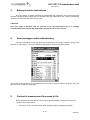
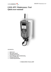
DLC – SPY
maintainance tool
User manual
DLC SPY 2.0 maintenance tool
User manual
2 / 11
Version 1
DLC SPY 2.0 maintenance tool
User manual
CONTENTS
1.
Quick Start ........................................................................................................ 4
1.1.
Check the list of supplied items .................................................................... 4
1.2.
Connect DLC SPY tool with LV connecting cables and testing nibs ............. 5
1.3.
Connect PDA device with dedicated connector to the DLC SPY tool ........... 5
1.4.
Power up DLC SPY tool ............................................................................... 5
1.5.
Start DLC SPY application on PDA device ................................................... 5
2.
Front panel operation ....................................................................................... 7
3.
Battery insertion instructions .......................................................................... 8
4.
Error messages and troubleshooting ............................................................. 8
5.
Content of measurement line saved in file ..................................................... 8
6.
Tutorial .............................................................................................................. 9
7.
Technical specification of DLC SPY maintenance tool ............................... 11
3 / 11
Version 1
DLC SPY 2.0 maintenance tool
User manual
1.
Quick Start
The following steps will help you to verify that the DLC –SPY tool is ready for use.
1.1.
Check the list of supplied items
Verify that you have received the following items with your DLC SPY tool and that you have a
recommended type of PDA (personal digital assistant) unit.
Recommended AC charger with DC output voltage 8V and max. current 500mA. 4VA
DLC SPY maintenance tool
Two LV (low voltage) connecting cables and testing nibs
DOLPHIN, iPAQ COMPAQ MODEL 3970 or similar Windows Mobile device
Application software DLC_SPY V2.0 installed on PDA with Win Mobile 4.2 / 5.0 or Win CE5.0
Four rechargeable NiMH batteries 1.2V with capacity greater than 1800mAh
DLC SPY maintenance tool
LV connecting cable
Testing nib
4 / 11
Version 1
DLC SPY 2.0 maintenance tool
User manual
1.2.
Connect DLC SPY tool with LV connecting cables and testing nibs
On the upper side of the DLC SPY tool there are two LV connecting terminals that are used to
connect the DLC SPY tool to low voltage network on phase T and zero terminals with special LV
connecting cable and testing nibs.
1.3.
Connect PDA device with dedicated connector to the DLC SPY tool
1.4.
Power up DLC SPY tool
Power switch is located on the right side of the DLC SPY tool. Power switch must be pressed
in order to start the operation of DLC SPY. When the DLC SPY maintenance tool starts to operate the
green LED marked as POWER ON lights up.
1.5.
Start DLC SPY application on PDA device
After starting the application on PDA device the carrier frequency setup window is displayed.
The desired carrier frequency must be selected in order to continue. Please note that in most networks
Iskra setup 1 should be selected.
After selecting the appropriate setup another window appears asking you whether you want to save
the measurement data or not. If you hit YES you have to specify the name of the file and destination
folder. The maintenance tool front panel is then displayed with four log windows, two buttons and
three graph windows.
5 / 11
Version 1
DLC SPY 2.0 maintenance tool
User manual
LV connecting terminals
LED indication
Power switch
DOLPHIN power on button
6 / 11
Version 1
DLC SPY 2.0 maintenance tool
User manual
2.
Front panel operation
During DLC SPY maintenance tool operation, communication traffic over LV grid is possible to
monitor with several parameters presented and described in table below.
POSITION
IDENTIFICATION
DESCRIPTION
1
DESYNC button
2
3
CLR button
Communication traffic log window
4
6
Signal to noise level on first
carrier - channel
Signal to noise level on second
carrier - channel
Rx power
7
Phase
8
FER
9
Noise floor
Desynchronize DLC SPY from mains pilot
signal
Clears the content of all windows
Displays captured messages with source and
destination addresses, data frame CRC check
status, initial credit, current credit and
demodulation method.
Displays last 100 measured signal to noise
ratios in the FIFO circular buffer manner.
Displays last 100 measured signal to noise
ratios in the FIFO circular buffer manner.
Displays last 100 measured power levels of
received signal in the FIFO circular buffer
manner.
Displays electrical phase position of received
communication signal in degrees. Possible
values are 0, ±60, ±120 and 180.
Displays frame error rate of the last 100
received data frames in percentage.
Displays average of the last 25 measurements
of noise floor in dBm.
5
1
2
3
4
5
7
8
6
9
7 / 11
Version 1
DLC SPY 2.0 maintenance tool
User manual
3.
Battery insertion instructions
DLC SPY device is entirely powered by rechargeable set of batteries (four pieces) that must
charged with appropriate charging unit not included in dlc spy maintenance tool. Place for a batteries
insertion is on the back side of the dlc spy case.
CAUTION!
Prior first usage of batteries that are included in dlc spy maintenance tool it is strongly
recommended to be charged with dedicated charging device at least 10 hours.
4.
Error messages and troubleshooting
If there is something wrong with DLC SPY maintenance tool (empty batteries, wrong setup
selection or other failure...) an error message is displayed as shown in the picture below.
In this case you must tap OK on the displayed error window in order to continue using DLC SPY unit
after the cause of failure is terminated.
5.
Content of measurement line saved in file
During measurement task with DLC SPY tool the measured data is possible to save in file.
The line content is as follows:
-
FCS_OK or FCS_FAIL: data frame check sequence status regarding 24 bit CRC.
8 / 11
Version 1
DLC SPY 2.0 maintenance tool
User manual
-
Source address of data frame.
Destination address of data frame.
Initial credits of data frame.
Current credits of data frame.
SNR_0_max: maximum SNR value on the first channel during measurement.
SNR_0_min: minimum SNR value on the first channel during measurement.
SNR_1_max: maximum SNR value on the second channel during measurement.
SNR_1_min: minimum SNR value on the second channel during measurement.
Demodulation method: possible values are FSK, FSK_1, FSK_0, ASK_1 and ASK_0.
Reception gain of the AGC (automatic gain control) of modem in dB with steps of 6 dB
from 0 to 42.
Measured values in line content are separated by semicolon (;) notation.
6.
Tutorial
The DLC SPY maintenance tool provides monitoring of the packet traffic on the LV grid and
the communication parameters of the received signals in the connecting point. During testing it should
be observed that the DLC SPY maintenance tool is connected to the connection terminals of the meter
unit as shown on the next picture. The main purpose of this tool is to find the reason why in certain
point of the LV grid communication is not possible. Most probably the highly attenuated transmitted
signal at the receiving point is resulting in the received power of the signal being below -32 dBm,
which is the minimum required power of received signal for successful synchronization and package
reception. The second reason is a high noise level with many noise sources and different noise signal
characteristics. In this case we have low SNR levels on one channel and sometimes even on both
channels. According to the length of the physical packet transmitted the minimum required frame error
ratio (FER), if SNR level is more than +5dB. The third reason could be a failure of the meter unit which
results in meter unit not responding to incoming messages. This particular failure can be diagnosed if
we can detect messages that are transmitted from the client side (the data concentrator) and other
servers (meter units) at the meter connecting terminals. The following table summarizes all possible
reasons of the communication blackout at observed network point.
Reason for communication
blackout with meter unit
Measured levels of
signals
Troubleshooting
SNR level on both
channels is less than
+5 dB
Check SNR level on other two LV
connection terminals and if the levels are
the same, the meter should be replaced
with a substitution meter (other
communication media, GSM, PSTN...).
Otherwise reconnect T phase terminal of
the meter unit to the phase where the best
levels of SNR are measured.
High levels of Noise floor in
dBm when no packets received
Noise floor is more than
–15 dBm
A jamming signal is present on LV grid.
Check the level of Noise floor level on
other phases and if SNR level is high
enough, reconnect the T phase of the
meter unit to the phase where the best
level of SNR is measured.
All messages from client (the
data concentrator) and other
servers (meter units) are
received on the DLC SPY but
the observed meter unit is not
installed (no DLC flag on meter
display)
Rx received power is
more than –32 dBm
and SNR_0 and SNR_1
levels are more than +5
dB on both channels
Replace current DLC meter unit with new
DLC meter unit.
Low signal to noise levels on
both channels
9 / 11
Version 1
DLC SPY 2.0 maintenance tool
User manual
Low signal to noise levels on
both channels
SNR level on both
channels is less than
+5 dB
High FER (frame error ratio)
but SNR levels are good
Levels higher than 5 %
Sometimes low SNR level at
measurement point could be result of low
communication signal level due to the
strong attenuation. If attenuation is a
result of network topology (long distances
with many network branches) we can
extend signal level with placing fixed
repeater (additional meter unit) between
data concentrator and meter unit.
There is high probability that some other
DLC communication system is running in
parallel. Parallel DLC system can affect
on our system due to the frequency
spectrum overlap or impedance drops
during packet transmition.
Connecting DLC SPY maintenance tool to the LV connection terminal of the meter unit
10 / 11
Version 1
DLC SPY 2.0 maintenance tool
User manual
7.
Technical specification of DLC SPY maintenance tool
Max. Power Consumption
LV Connection Terminal
Voltage
Max. Operating Time with
fully charged batteries
Max. Charging Time with
total empty batteries
Weight
Dimensions (W x L x H)
1
UNITS
VALUE
mW
V
350
230 20%
(1)
h
10
h
6
Kg
mm
0.45
195 x 101 x 44
Capacity of batteries falls during time and with number of charging cycles. If operating time drops too much that normal
maintenance is no longer possible, replace batteries with new ones.
UK DISTRIBUTOR:
SMS Metering Limited
41 London Road, Castle Court, Reigate, Surrey RH2 0DD
T: 0845 604 7244
E: [email protected]
W: www.smsmetering.co.uk
______________________________________________________________________________________________________
Owing to periodical improvements of our products the supplied products can differ in some details from data stated in the Technical Description.
______________________________________________________________________________________________________
Iskraemeco, Energy Measurement and Management
4000 Kranj, Savska loka 4, Slovenia
Telephone: (+386 4) 206 40 00, Telefax: (+386 4) 206 43 76
Published by Iskraemeco, Marketing
Data subject to alternation without notice.
______________________________________________________________________________________________________
11.03.2009
DLC_SPY_User_manual.doc
11 / 11
Version 1